Loading ...
Loading ...
Loading ...
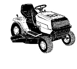
Compare the battery in your lawn tractor (located
under the seat) with the illustration above. Type "A"
batteries are activated and are ready to use. Type
"B" batteries must be filled with battery fluid (acid)
and charged before they are put into service.
Follow instructions which apply to the battery in
your lawn tractor only.
Activating&ChargingBattery
(Type "B" Battery Only)
WARNING: Do not activate battery (i.e. fill
with battery acid) until battery is actually
placed in service. Read warnings about
battery usage in the previous page before
activating the battery.
Pivot the seat pivot bracket forward. Unhook the
strap which secures the battery (hook is on rear
frame, under the fender). Disconnect the positive
cable from the positive terminal. Save the hardware
for reassembly.
Remove the battery from the lawn tractor, paying
attention to how the battery is placed in the unit,
and how the drain tube (attached to the battery) is
routed.
Activate the battery as instructed in the "Quick
Start" brochure included with the battery fluid. Read
instructions carefully.
NOTE: You can continue to assemble the lawn tractor
while the battery is standing for 30 minutes after acid
fill-up, and later while you are charging the battery.
IMPORTANT: To obtain maximum life from the battery,
charge it prior to initialuse.
Battery P/N 725-1705D: Charge at 2-3 amps for
one hour.
Battery P/N 725-1707D, 725-0453G, and 725-
1750: Charge at 6 amps for one hour.
Charge battery after the 30-minute standing period.
NOTE: If you charge the battery at a Iower AMP rate,
use a hydrometer to make sure the battery is
completely charged. The hydrometer should read 1.260
minimum at an electrolyte temperature of 60-110°F.
WARNING: Do not charge the tractor
battery at more than 6 amps.
AttachingSteeringWheel
The hardware for attaching the steering wheel has
been packed insidethe steering wheel. Carefully pry
offthe steering wheel cap and remove the hardware.
Remove the steering bellow from the lift lever on
the right side of the tractor.
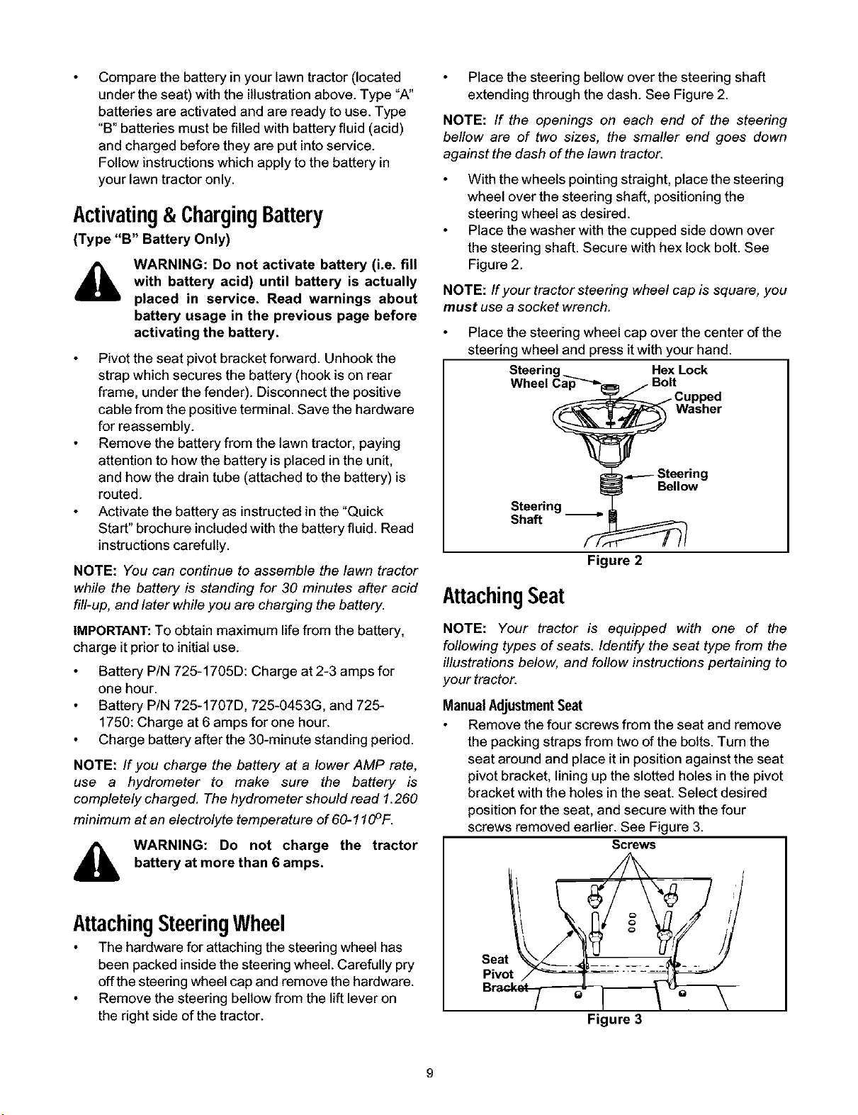
Place the steering bellow over the steering shaft
extending through the dash. See Figure 2.
NOTE: If the openings on each end of the steering
bellow are of two sizes, the smaller end goes down
against the dash of the lawn tractor.
With the wheels pointing straight, place the steering
wheel over the steering shaft, positioning the
steering wheel as desired.
Place the washer with the cupped side down over
the steering shaft. Secure with hex lock bolt. See
Figure 2.
NOTE: Ifyour tractor steering wheel cap is square, you
must use a socket wrench.
Place the steering wheel cap over the center of the
steering wheel and press itwith your hand.
Steering Hex Lock
Wheel Cap-'_"-_ j Bolt
j Cupped
_ Washer
t-=_----Steering
_ Bellow
Steering
Shaft
Figure 2
AttachingSeat
NOTE: Your tractor is equipped with one of the
following types of seats. Identify the seat type from the
illustrations below, and follow instructions pertaining to
your tractor.
ManualAdjustmentSeat
Remove the four screws from the seat and remove
the packing straps from two of the bolts. Turn the
seat around and place it inposition against the seat
pivot bracket, lining up the slotted holes in the pivot
bracket with the holes in the seat. Select desired
position for the seat, and secure with the four
screws removed earlier. See Figure 3.
Screws
Seat
Q
Figure 3
Loading ...
Loading ...
Loading ...