Loading ...
Loading ...
Loading ...
BeltReplacement
WARNING: Disconnect the spark plug
wire(s) and ground it against the engine.
Block the wheels of the unit.
NOTE: Figure 22 and Figure 26are shown with the unit
tipped up for clarity. It is not necessary to tip the unit to
remove the belts. However, for convenience, if you
decide to tip it, remove the battery from the unit first.
To prevent gasoline leakage, drain the gasoline, or
remove the fuel tank cap. Place a thin piece of
plastic over the neck of the fuel tank and screw on
the cap. Be certain to remove the plastic when
finished changing the belts. Block unit securely.
DeckBelt(38" and 42" Decks)
Place the lift lever in the engaged (all the way
forward) position.
Disconnect the spring which is attached to a
bracket on the transaxte, inside the right rear wheel.
Use a spring puller or other suitable tool.
NOTE: When reassembling, make certain belt keeper
pins are assembled in the same locations from which
they were removed. See Figure 22.
Pulley
Figure 22
Place the lift lever in the BLADES STOP position.
Remove the belt keeper pins from the lower frame.
Unhook the deck belt from the engine pulley.
Place the lift lever in the engaged (all the way
forward) position.
Disconnect the stabilizer plate from the stabilizer
shaft assembly by removing the hairpin clips and
flat washers and sliding out the rod.
Disconnect the six deck links by removing the
hairpin clips and flat washers.
Place the lift lever in the BLADES STOP position.
Slide the deck from beneath the lawn tractor.
Remove the belt guards at each deck pulley by
removing the self-tapping screws. See Figure 23.
Remove and replace the belt, reassemble following
the instructions in reverse order.
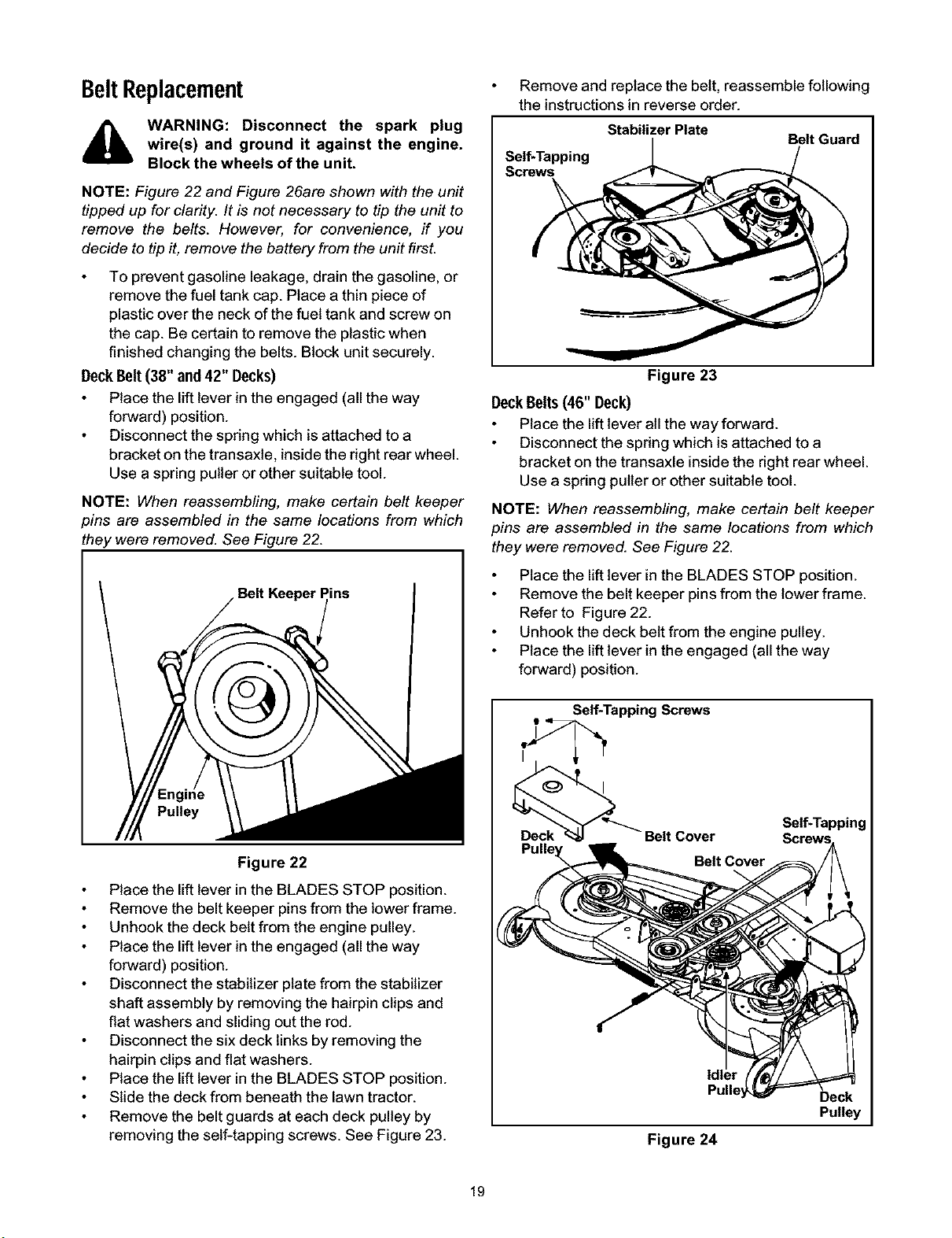
Stabilizer Plate
Belt Guard
Self-Tapping
Screws
Figure 23
DeckBelts(46" Deck)
Place the lift lever all the way forward.
Disconnect the spring which is attached to a
bracket on the transaxle inside the right rear wheel.
Use a spring puller or other suitable tool.
NOTE: When reassembling, make certain belt keeper
pins are assembled in the same locations from which
they were removed. See Figure 22.
Place the lift lever in the BLADES STOP position.
Remove the belt keeper pins from the lower frame.
Refer to Figure 22.
Unhook the deck belt from the engine pulley.
Place the lift lever in the engaged (all the way
forward) position.
Self-Tapping Screws
Cover
Self-Tapping
Belt Cover
Pulley
Figure 24
19
Loading ...
Loading ...
Loading ...