Loading ...
Loading ...
Loading ...
Replace the transmission panel and parking brake
knob.
Remove the blocks from under the frame and test
the operation of the tractor.
DeckLeveling
Ifthe tractor is cuttinggrass unevenly, level the deck
following instructions in the Assembly Section.
CuttingDeckEngagement
The cutting deck engagement may be adjusted to
ensure that deck is disengaged when lift lever is in
BLADES STOP position. Correct adjustment as
follows.
With the engine off, place the lift lever in the highest
cutting position (first position).
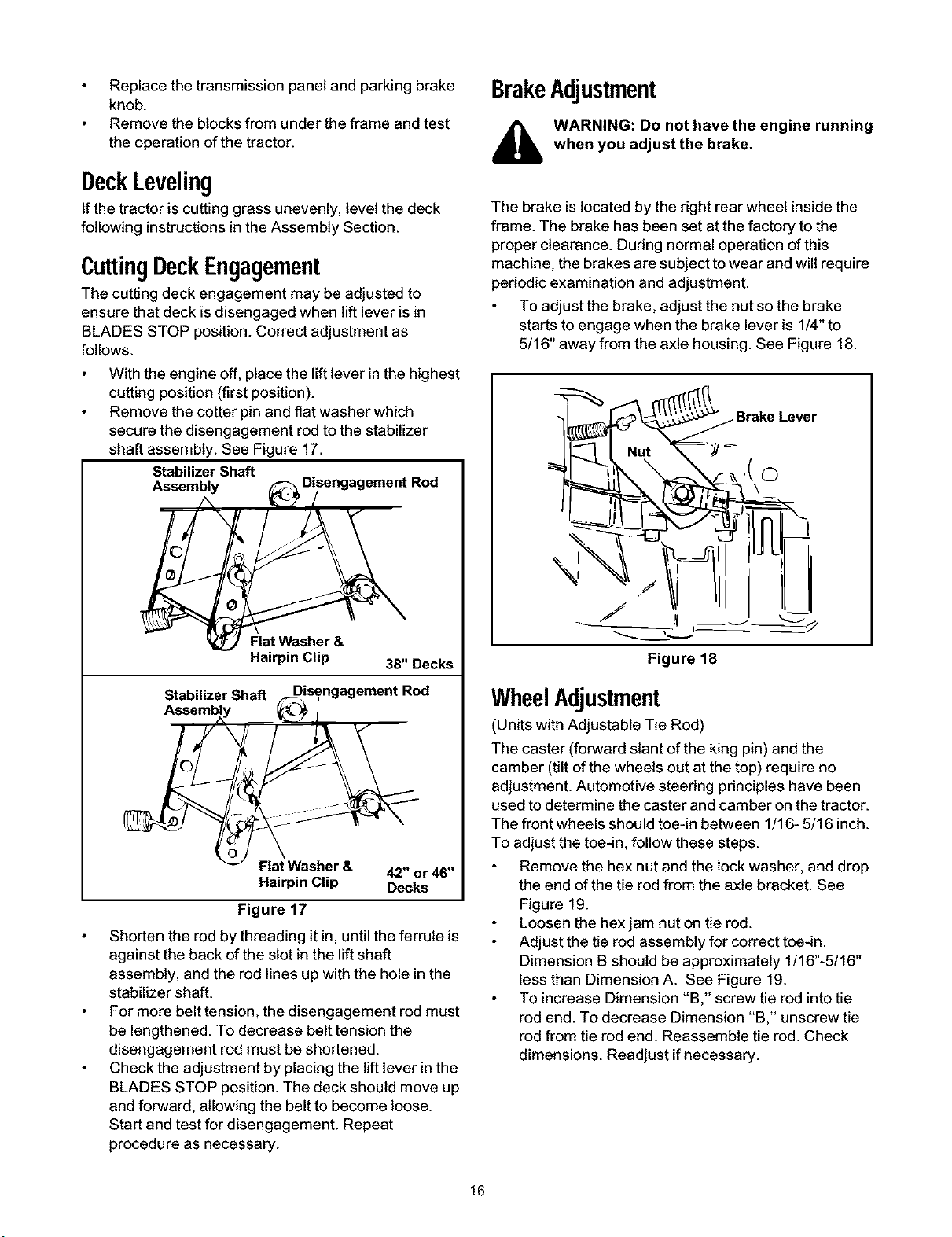
Remove the cotter pin and flat washer which
secure the disengagement rod to the stabilizer
shaft assembly. See Figure 17.
Stabilizer Shaft
Assembly
Stabilizer Shaft
f
Flat Washer &
Hairpin Clip 38" Decks
Disengagement Rod
Flat Washer & 42" or 46"
Hairpin Clip Decks
Figure 17
Shorten the rod by threading it in, untilthe ferrule is
against the back of the slot in the liftshaft
assembly, and the rodlines up with the hole inthe
stabilizer shaft.
For more belt tension, the disengagement rod must
be lengthened. To decrease belt tension the
disengagement rod must be shortened.
Check the adjustment by placing the lift lever in the
BLADES STOP position. The deck should move up
and forward, allowing the belt to become loose.
Start and test for disengagement. Repeat
procedure as necessary.
BrakeAdjustment
A ARNING: Do not have the engine running
when you adjust the brake.
The brake is located by the right rear wheel inside the
frame. The brake has been set at the factory to the
proper clearance. During normal operation of this
machine, the brakes are subject to wear and will require
periodic examination and adjustment.
To adjust the brake, adjust the nut so the brake
starts to engage when the brake lever is 1/4" to
5/16" away from the axle housing. See Figure 18.
_Brake Lever
Figure 18
WheelAdjustment
(Units with Adjustable Tie Rod)
The caster (forward slant ofthe king pin) and the
camber (tiltof the wheels out at the top) require no
adjustment. Automotive steering principles have been
used to determine the caster and camber on the tractor.
The front wheels should toe-in between 1/16- 5/16 inch.
To adjust the toe-in, follow these steps.
Remove the hex nut and the lock washer, and drop
the end ofthe tie rodfrom the axle bracket. See
Figure 19.
Loosen the hex jam nut on tie rod.
Adjust the tie rod assembly for correct toe-in.
Dimension B should be approximately 1/16"-5/16"
less than Dimension A. See Figure 19.
To increase Dimension "B," screw tie rod intotie
rod end. To decrease Dimension "B "unscrew tie
rod from tie rod end. Reassemble tie rod. Check
dimensions. Readjust if necessary.
16
Loading ...
Loading ...
Loading ...