Loading ...
Loading ...
Loading ...

16 17INSTALLING THE FREESTANDING COOKERWIRING REQUIREMENTS
WIRING REQUIREMENTS
The cooker MUST be installed in compliance with:
• Wiring connections in AS/NZS 3000 Wiring Rules.
• Local regulations, municipal building codes and
other statutory regulations.
For New Zealand Only:
The cooking range must be connected to the supply by
a supply c
or
d fitted with the appropriately rated plug
that is compatible with the socket-outlet fitted to the
final sub-circuit in the fixed wiring that is intended to
supply this cooking range.
Supply cord size required:
WFE9515SD - 2.5mm
2
The Data plate gives information about rating and is
located behind the bottom of the oven door.
• A functional switch MUST be provided near the
appliance in an accessible position (AS/NZS 3000).
• Wiring MUST be protected against mechanical failure
(AS/NZS 3000).
• Disconnection in the fixed wiring must occur in
accordance with the AS/NZS 3000 wiring rules.
• The cooker MUST be properly earthed.
• This range must be connected with cable of 75°C
rating minimum.
• This product has passed the insulation resistance test
after manufacture. If the resistance reading is low at
installation, it is probably caused by moisture from
the atmosphere being absorbed by the elements after
the range has been produced. (Pass at 0.01 MΩ as per
AS/NZS 3000 - “Wiring Rules”).
Note: When connections are made to a multi-phase
230/240V supply, the bridge piece MUST be removed
from between the active connections.
Rated power input
MODEL TOTAL KW A1 KW A2 KW
WFE9515SD 4.5 4.5 -
IMPORTANT
Before you cook in your new oven it is important that
the protective oils used in the manufacture of the
product be removed.
• Make sure that the room is well ventilated (to allow
smoke to escape).
• Run the grill on high for 30 minutes without grill dish.
• Then run the oven on 180°C for 1 hour.
Connecting to services and commissioning
This appliance must be installed by an authorised
person, according to all codes and regulations of:
• Electrical supply authorities.
• Building regulations.
• Local government and council authorities.
• AS/NZS 5601.1.
• AS/NZS 3000.
Securing points
Plastic clips
Plastic clip
Hard wiring detail
1. Remove terminal cover plate from rear panel
of appliance.
2. Fit wires through hole in cover plate and make
connections to terminals.
3. Engage wires into plastic clip. Secure plastic
clip with two long silver screws (supplied in
separate bag).
4.
Replace cover plate onto rear panel.
INSTALLING THE FREESTANDING COOKER
Checking piping size
To work out a suitable pipe size for connection use the
information in this table.
GAS TYPE NATURAL
GAS
UNIVERSAL
LPG
WFE9515SD 54.2MJ/h 45.5MJ/h
For information and requirements about construction
and capacity of consumer piping refer to AS/NZS 5601
series of standards.
Gas connection
Read these points before connecting to the gas supply:
• The appliance is preset for natural gas use, if LPG is to
be used see Conversion to LPG section.
• Gas installation must be made in accordance with AS/
NZS 5601.1, the local gas fitting regulations, municipal
codes and other statutory regulations.
• The gas connection point is a ½” BSP external thread
located at the rear of the appliance as shown.
• The regulator is to be fitted to the manifold inlet at
the rear of the appliance and the connection is sealed
using a tape or jointing compound suitable for gas
connections. The consumer piping is then connected
to the inlet of the regulator, either
1. directly, or
2. using a hose assembly and in accordance with
AS/NZS 5601.1 (High level connection) together
with the supplied elbow. The elbow is fitted to the
inlet of the regulator and oriented to allow the
hose to hang downward. The connection thread
between the regulator and elbow is sealed using
a tape or jointing compound suitable for gas
connections.
This appliance is supplied set up for Natural Gas usage.
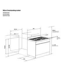
Model WFE9515SD
278
673
696
95
168
Gas connection point
to regulator
Electrical cable
entry point
Gas hose restraints
point to regulator
Gas pressures
The following table shows the supply and operating
pressures for various gases.
GAS TYPE
NATURAL
GAS
UNIVERSAL
LPG
Supply pressure at inlet
to appliance regulator
(if fitted)
1.13 (kPa)
Minimum
2.75*
(kPa)
Operating pressure at
appliance test point
1.00 (kPa) 2.6 (kPa)
*If the regulator is placed upstream of the cooker inlet, as is normal
for cookers operating on LPG, then the supply pressure and
operating pressure are the same.
Injectors
The following table shows the injector sizes for
each burner.
INJECTOR ORIFICE NATURAL
GAS
UNIVERSAL
LPG
Low heat burner 1.00mm 0.55mm
Medium heat burner 1.35mm 0.70mm
High heat burner 1.60mm 0.90mm
Intense heat wok burner 1.75mm 1.00mm
Loading ...
Loading ...
Loading ...