Loading ...
Loading ...
Loading ...
8
7.0 Set-Up and Assembly
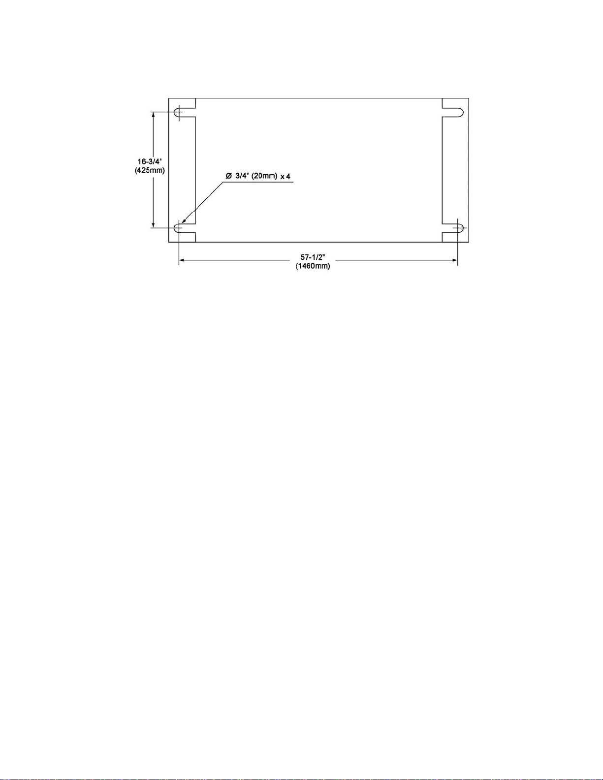
7.1 Hole center dimensions
Figure 2
7.2 Unpacking
Open shipping container and check for shipping
damage. Report any damage immediately to
your distributor and shipping agent. Do not
discard any shipping material until the Shear is
assembled and running properly.
Compare the contents of your container with the
following list to make sure all parts are intact.
Missing parts, if any, should be reported to your
distributor. Read the instruction manual
thoroughly for assembly, maintenance and
safety instructions.
Contents of the Shipping Container
1 Pneumatic Shear with Foot Pedal
2 Front Arm Extensions
1 Front Stop, with hardware
1 Rear Stop, with hardware
2 Scale Rods
2 Adjusting Block Assemblies
1 Bevel Gauge, with hardware
1 Instructions and Parts Manual
1 Warranty Card
1. Remove the crating material from around
the machine.
2. Clean the protectant from all exposed metal
surfaces with a mild solvent or kerosene,
and a soft rag. Do not use lacquer thinner,
paint thinner, or gasoline, as these may
damage painted surfaces.
3. Coat all machined surfaces with a light coat
of oil to inhibit rust.
4. Remove the bolts holding the machine to the
skid.
5. Place straps below the table (you may have
to remove front cover), and use propery
rated lifting equipment to move the machine
to a level foundation. Machine location must
allow access to all sides. Use shims at floor
if needed.
Assembly Note: Prior to shipment, the
pneumatic shear is adjusted at the factory for
proper alignments and operation. If the machine
does not operate properly or the stand does not
sit squarely on the floor, proceed to Set-Up
Adjustments.
6. When the machine sits evenly, secure it to
the floor using proper fasteners. Refer to
Figure 2.
7.3 Stop assemblies
Refer to Figure 1. (Numbers in parentheses
refer to corresponding part in exploded view.)
1. Attach the two front arm extensions (6) to
the bed with four hex cap screws (7) and
four washers (76). Level arm extension
surfaces with the table before tightening.
2. Attach front stop (71) to front arm extensions
with T-screws (72) and wing nuts (74).
Loading ...
Loading ...
Loading ...