Loading ...
Loading ...
Loading ...
10
8.0 Adjustments
8.1 Table and blades
1. If the table requires adjustment, loosen four
bolts (21); do not remove. Loosen nuts on
the adjusting screws (18,19). The bed must
rest squarely on the right and left hand side
panels at all four corners while screws are
loose. Shim legs at floor if necessary.
Tighten hardware.
2. Use set screw (18) and hex cap screw (19),
to adjust the lower blade toward or away
from the upper blade. The distance between
the upper and lower blades should be 0.002-
0.005”. Do not let the blades overlap.
3. Connect machine to electrical supply, and
adjust the air pressure until the gauge reads
approximately 90 psi.
4. Place a heavy sheet of paper
(~0.005”/0.13mm) in the cutting position,
along the entire length of the bed.
5. Turn switch to ON and press the foot pedal.
6. If the shear does not cut the paper, move
the lower blade toward the upper blade.
7. If the shear cuts the paper on the ends, but
not the center, turn the tie-rod adjusting
screw (37), clockwise until the paper is cut
the entire length.
8. If the shear cuts the paper in the center, but
not the ends, turn the tie-rod adjusting screw
(37) counter-clockwise until the paper is cut
the entire length.
9. Make sure the scales (15,16) on top of the
table are square to the blade, and also show
the correct distance from the blade.
10. Make test cuts to verify that the scales are
correct.
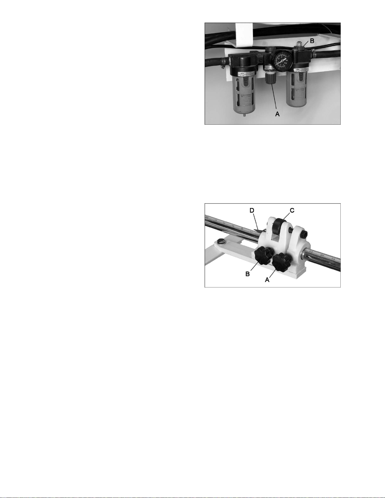
8.2 Air regulator
Refer to Figure 4.
1. Connect air source to quick connector.
2. Set the desired air pressure between 90-120
PSI using the pressure dial (A) on the
filter/regulator (clockwise to increase). Lock
the setting by pushing down the pressure
dial. Pull up on the dial to readjust a setting.
3. Adjust oil flow using dial (B) at top of
lubricator. A setting of 2 drips per minute is
sufficient for regular operation.
Figure 4
8.3 Rear stop micro adjust
Refer to Figure 5.
The knurled dial on the adjusting block can be
used for micro positioning of the rear stop.
Tighten knob (A) and make knob (B) snug.
Rotate dial (C) until pointer (D) is at desired
position. Tighten knob (B).
Figure 5
8.4 Hold-down tension
The spring return can be adjusted on the hold
down (3) by tightening the lower hex nuts (10).
8.5 Gibs
There are three hex cap screws (32) that can be
adjusted for play in each shim (31). Loosen the
jam nuts (33) to turn the screws. Adjust for
smooth travel. Retighten jam nuts.
Loading ...
Loading ...
Loading ...