Loading ...
Loading ...
Loading ...
7 English
Refer to Table 2 for the processing dimensions of the •
fl are.
Use the fl are nut provided with the unit.•
Apply ether oil or ester oil only to inner side of the •
fl are and screw in the fl are nut three to four turns fi rst
by hand at the time of connecting the fl are nut.
(Refer to Fig. 4)
Fig. 4
Apply ester oil or ether oil
only to inner side of flare.
•
Refer to Table 2 for the corresponding tightening torque.•
Table 2
Pipe
size
Tightening torque
Flare
dimensions
A (in.)
Flare shape
φ 3/8 26.7 ±2.6 lbf·ft
0.504 – 0.520
9
0
˚
±
2
˚
4
5
˚
±
2
˚
A
R0.016-0.031
φ 5/8 50.6 ±5.0 lbf·ft
0.760 – 0.776
CAUTION
Do not excessively tighten the fl are nut.•
Doing so will break the fl are nut and refrigerant leakage may
result.
Make sure that all parts around the fl are are free of oil. •
The drain pan and the resin part may be deteriorated if oil is
attached.
If no torque wrenches are available, refer to Table 3 as a •
standard.
When the fl are nut is tightened with the spanner, the
tightening torque should increase suddenly. Tighten the
fl are nut further for the corresponding angle shown in
Table 3.
Table 3
Pipe size Further tightening angle
Recommended arm length of
tool
φ 3/8 60 to 90 degrees Approx. 7-7/8 in.
φ 5/8 30 to 60 degrees Approx. 11-13/16 in.
On completion of installation work, (2) check that there is no
gas leakage.
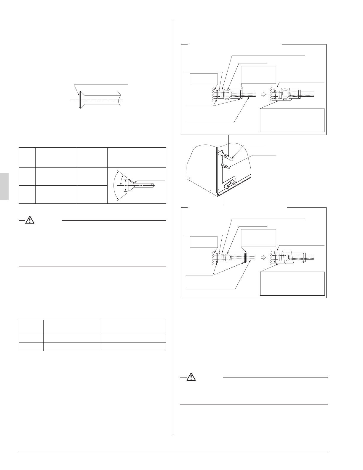
Refer to the illustration on the right-hand side and be sure (3)
to perform heat insulation work on the piping joints after
gas leakage checks. (Refer to Fig. 5)
Heat insulation procedure for gas piping
Insulation material
for piping
(on unit side)
Insulation material
for piping (field supply)
Make sure that
the seam faces
upward.
Clamp
material (1)
(accessory)
Gas pipe
Liquid pipe
Flare nut joint
Attached to
the surface.
Insulation for fitting (7) (accessory)
Sealing pad (small) (8)
(accessory)
Wrap the Sealing pad (small) (8)
around the portion from the
surface of the main unit to the
upper part of the flare nut joint.
Insulation material
for piping (field supply)
Wrap the Sealing pad (small) (8)
around the portion from the
surface of the main unit to the
upper part of the flare nut joint.
Fig. 5
Heat insulation procedure for liquid piping
Insulation material
for piping
(on unit side)
Make sure that
the seam faces
upward.
Clamp
material (1)
(accessory)
Main unit
Flare nut joint
Attached to
the surface.
Insulation for fitting (6) (accessory)
Sealing pad (small) (8)
(accessory)
Use the Insulation for fi tting (6) and (7) provided to the •
liquid piping and gas piping, respectively, and conduct
heat insulation work.
(Tighten both edges of the Insulation for fi tting (6) and
(7) for each joint with the Clamp material (1).)
Make sure that the joint of the Insulation for fi tting (6) •
and (7) for the joint on the liquid piping and gas piping
side faces upward.
Wrap the Sealing pad (small) (8) around the Insulation •
for fi tting (6) and (7) for the joint (fl are nut part).
CAUTION
Be sure to insulate any fi eld piping all the way to the piping •
connection inside the unit. Any exposed piping may cause
condensation or burns if touched.
01_EN_3P250363-4E.indd 701_EN_3P250363-4E.indd 7 6/9/2016 4:56:47 PM6/9/2016 4:56:47 PM
Loading ...
Loading ...
Loading ...