Loading ...
Loading ...
Loading ...
11 English
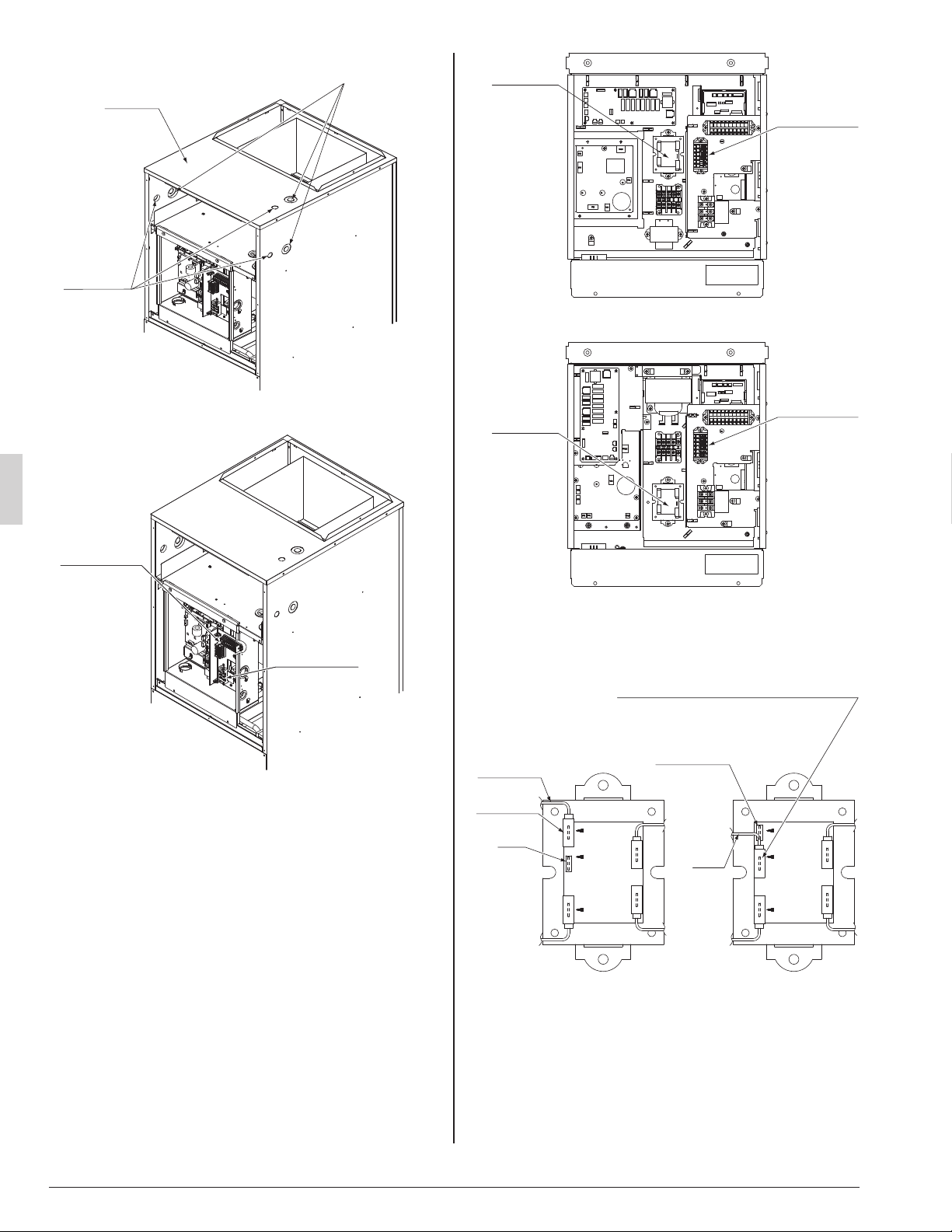
Remove the front panel (upper).(1)
Top panel
High-voltage
hole
Low-voltage
hole
Remove the electric component box cover.(2)
Terminal block
Terminal block
Pass the power supply wiring and the ground wire
(3)
through the top panel’s high-voltage hole (requires use of
conduit) and pass the remote controller wiring and trans-
mission wiring through the top panel’s low-voltage hole.
Pass the included insulation tube through the hole in the •
panel before connecting the electric wires and the
ground wire to the terminal block shown in Fig. 8.
Pass the included insulation tube through the hole in the •
panel before connecting the remote controller wiring
and transmission wires to the terminal block shown in
Fig. 8.
Then secure them in place with the included Clamp •
material (1) as shown in Fig. 8 to protect them from
external force from outside the unit.
If the power supply voltage is 208V, change the trans-•
former wire connection from the 240V terminal to the
208V terminal. (Refer to Fig. 9)
Transformer
Fig. 8
<FTQ18,24,30,36PBVJU models>
<FTQ42PBVJU model>
Terminal block
Terminal block
Transformer
Changing the transformer wire connection
208VCOM 240V
240V208VCOM
Wire (Red)
Cap
Fig. 9
(Change the
connection.)
(Connect the wire to the 208V terminal.
Be sure to insert the wire securely until
a clicking sound is produced.)
Connector
Wire
(Red)
Cap
Connector
230V power supply (factory set)®208V power suppy®
01_EN_3P250363-4E.indd 1101_EN_3P250363-4E.indd 11 6/9/2016 4:56:50 PM6/9/2016 4:56:50 PM
Loading ...
Loading ...
Loading ...