Loading ...
Loading ...
Loading ...
English 10
DANGER
Do not ground units to water piping, telephone wires or •
lightning rods because incomplete grounding could cause a
severe shock hazard resulting in severe injury or death, nor
to gas piping because a gas leak could result in an explo-
sion which could lead to severe injury or death.
LIST OF STANDARD WIRING EQUIPMENT8-2
Power supply wiring
(including ground wire)
Transmission wiring
Remote controller wiring
Protective
device
Size Wire Size
15A
Must comply with
local codes.
2-conductor,
stranded,
non-shielded
copper/PVC or
vinyl jacket
AWG18 – 16
NOTES
If the wiring is in a place where people it can be easily 1.
touched by people, install a ground-fault circuit interrupter
to prevent electric shock.
When using a ground-fault circuit interrupter, make sure to 2.
select one useful also to protection against overcurrent and
short-circuit.
When using a ground-fault circuit interrupter only for
grounding device, make sure to use a wiring interrupter
together.
The length of the transmission wiring and remote controller •
wiring are as follows.
Length of the transmission wiring and remote controller wiring
Outdoor unit – Indoor unit
Max. 3280 ft.
(Total wiring length: 6560 ft.)
Indoor unit – Remote controller Max. 1640 ft.
ELECTRICAL CHARACTERISTICS8-3
Units Power supply Fan motor
Model Hz Volts
Voltage
range
MCA MOP HP FLA
18 type
60
208/
230
Min. 187
Max. 229/
Min. 207
Max. 253
1.5
15
350
1.2
24 type 1.6 1.3
30 type 2.3 1.8
36 type 2.8 2.2
42 type 3.6 400 2.8
MCA: Minimum Circuit Amps (A)
MOP: Max Overcurrent Protective Device (A)
HP: Fan motor output (W)
FLA: Full Load Amps (A)
WIRING EXAMPLE9.
HOW TO CONNECT WIRINGS9-1
〈Precautions when laying power supply wiring〉
Wiring of different thicknesses cannot be connected to the •
power supply wiring terminal block. Slack in the power
supply wiring may cause abnormal heat.
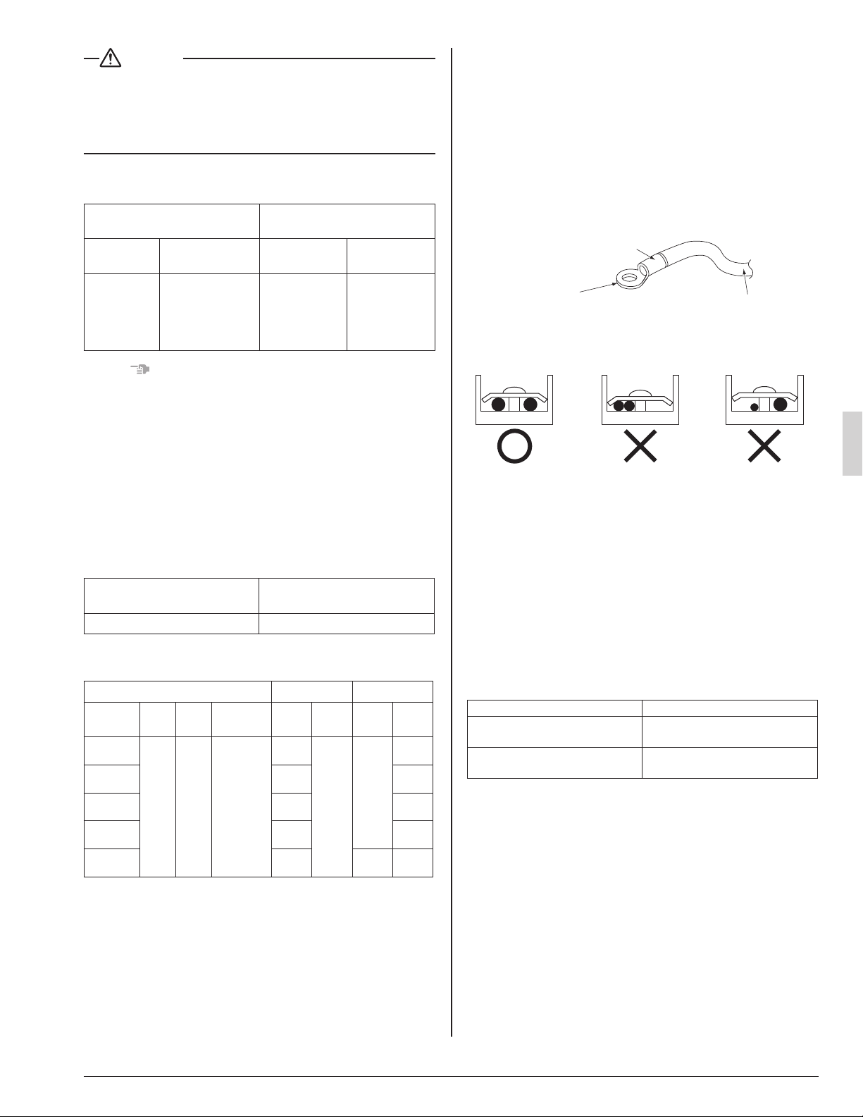
Use sleeve-insulated round crimp-style terminals for con-•
nections to the power supply wiring terminal block. When
none are available, connect wires of the same diameter to
both sides, as shown in the fi gure.
Electric wire
Round crimp-style terminal
Insulation sleeve
Connect wires of
the same gauge to
both sides.
Do not connect
wires of the same
gauge to one side.
Do not connect
wires of different
gauges.
If the wiring gets too hot due to loose power-supply wir-
ing, use the following precautions:
For wiring, use the designated power supply wiring and •
connect fi rmly, then secure to prevent outside pressure
being exerted on the terminal board.
Use the correct screwdriver for tightening the terminal •
screws. If the blade of screwdriver is too small, the head of
the screw might be damaged, and the screw will not be
properly tightened.
If the terminal screws are tightened too hard, screws might •
be damaged.
Refer to Table 4 for the tightening torque of the terminal •
screws.
Table 4
Terminal block Tightening torque (ft · lbf)
Remote controller / transmission
wiring terminal block (6P) (10P)
0.58 – 0.72
Power supply wiring terminal
block (3P)
0.87 – 1.06
01_EN_3P250363-4E.indd 1001_EN_3P250363-4E.indd 10 6/9/2016 4:56:50 PM6/9/2016 4:56:50 PM
Loading ...
Loading ...
Loading ...