Loading ...
Loading ...
Loading ...
8
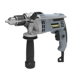
5. SWITCH LOCK-ON BUTTON (See Fig E)
Depress On/Off switch (6) then Lock-on Button
UHOHDVH2Q2IIVZLWFK¿UVWDQGWKHQWKH
Lock-on Button second. Your switch is now
locked on for continuous use. To switch off your
WRROMXVWGHSUHVVDQGUHOHDVHWKHRQRIIVZLWFK
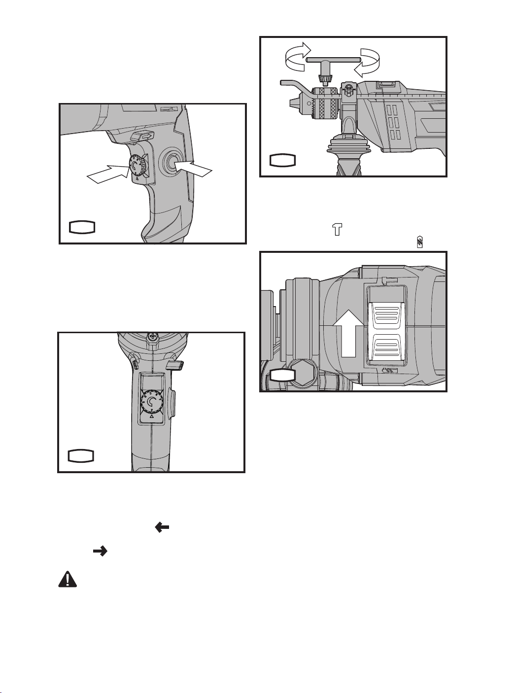
6. VARIABLE SPEED CONTROL (See Fig F)
$GMXVWWKHVSHHGFKDQJHNQREWRLQFUHDVH
or decrease the speed according to the material
and accessory to be used (also possible during
no load operation). Low speed will provide low
torque and high speed gives higher torque.
7. FORWARD AND REVERSE ROTATION
CONTROL (See Fig G)
For forward bit rotation, move the F/R rotational
switch to the left marked “
“. For reverse bit
rotation, move the F/R rotational switch to the right
marked “ “. Position the rotational switch to the
right to UHPRYHDMDPPHGELWWRR
NOTE: Never move the forward/reverse
switch whilst the drill in operation
or the on/off switch is locked as this will
damage the drill.
8. HAMMER OR DRILLING CONTROL (See
Fig H)
When drilling masonry and concrete choose the
hammer position “
”. When drilling in wood,
metal, plastic, choose the drill position. “ ”.
E
+
-
F
C
H
Loading ...
Loading ...
Loading ...