Loading ...
Loading ...
Loading ...
27
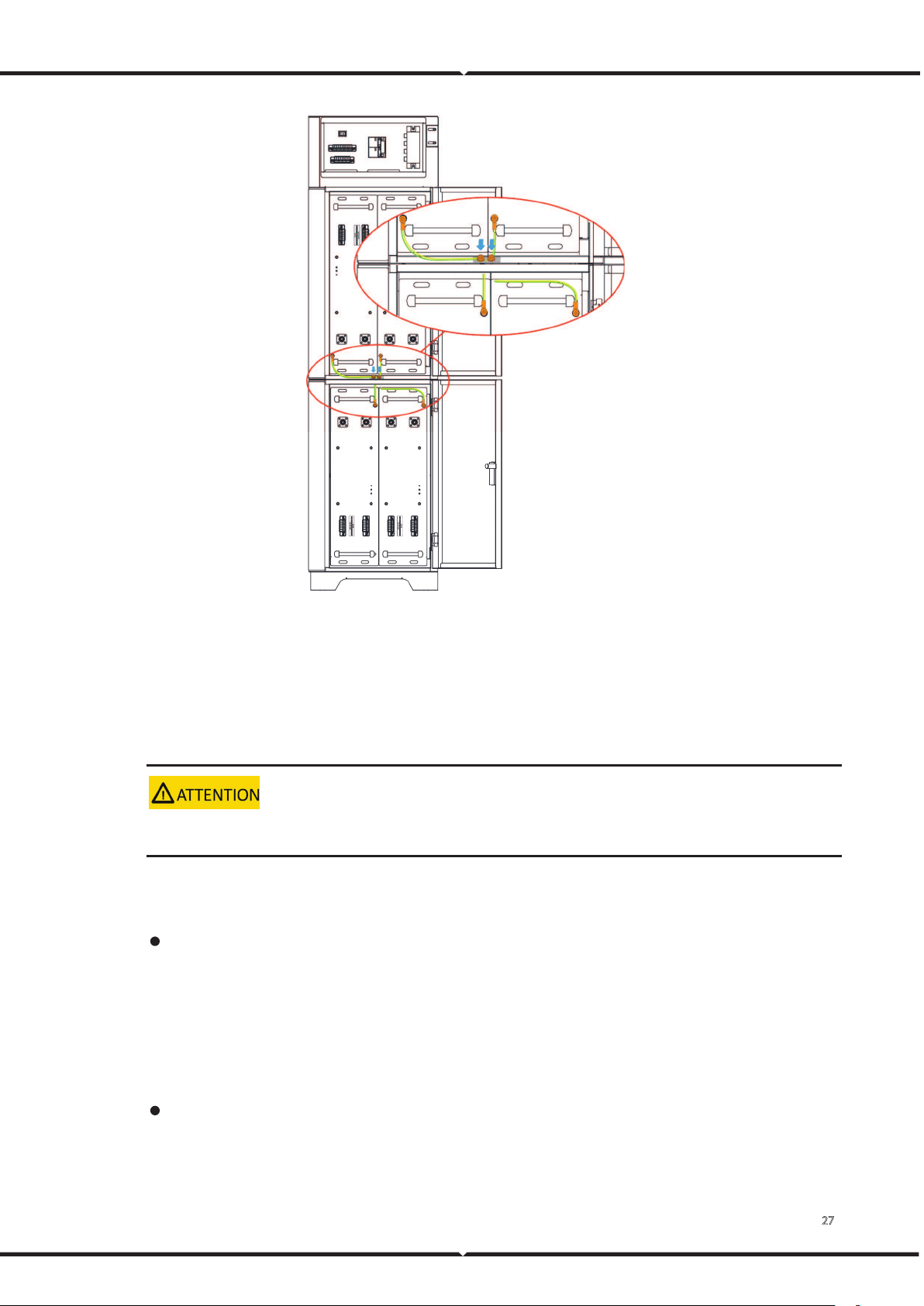
Figure 23. Battery module grounding
4.5 Connecting Power Cable
Context
Insulate installation tools to prevent electric shocks.
The battery module power cable connection method adopts the self-locking connector method. The
description of the self-locking connector is shown as follows:
The steps for connecting the self-locking connector are as follows:
A Adjust the direction of the self-locking connector to align with the battery module terminal.
B Rotate the self-locking connector slightly, and it will be sucked in automatically.
C After the self-locking connector is automatically sucked in, push it in slightly, and after hearing
a sound, the self-locking connector and the battery module terminal are connected.
Users need to press the buttons on the self-locking connector simultaneously when users need to
pull out the self-locking connector.
Loading ...
Loading ...
Loading ...