
Loading ...
Loading ...
Loading ...
15
3.2.4.3 PIN Definition
External communication port
The PIN definition of an external communication port is shown as follows.
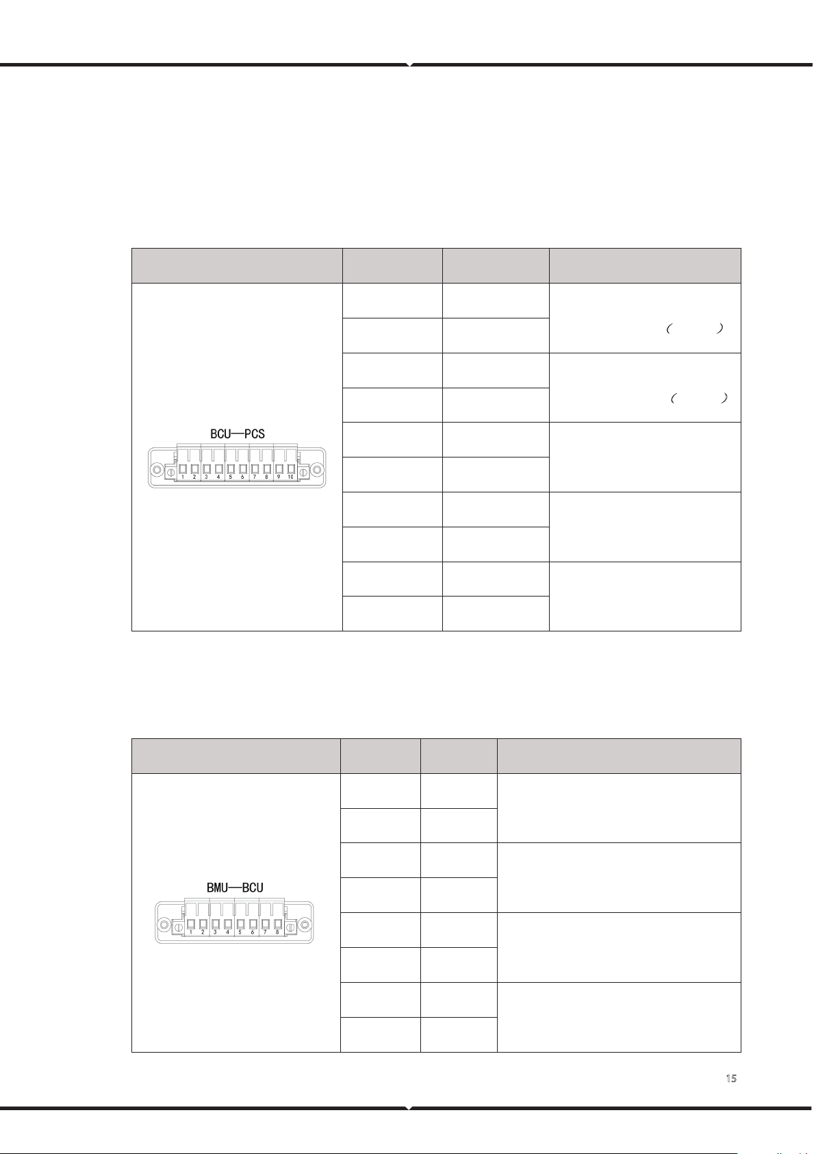
Table 7. External communication port PIN definition
Location schematic diagram Location Definition Remark
1 CAN1H
BCU communication, connect the
last high voltage box
(
Optional
)
2 CAN1L
3 CAN1H
BCU communication, connect the
next high voltage box
(
Optional
)
4 CAN1L
5 CAN2H
Inverter communication
6 CAN2L
7 DI+
Low voltage wake up
8 DI-
9 AC/L
AC input
10 AC/N
BMU communication port
The PIN definition of the BMU communication port is shown as follows.
Table 8. BMU communication port PIN definition
Location schematic diagram Location Definition Remark
1 V+
Battery module 24V power supply
2 V-
3 CAN0H
BMU communication, connect the last
battery module
4 CAN0L
5 V+
Battery module 24V power supply
6 V-
7 CAN0H
BMU communication, connect the next
battery module
8 CAN0L
Loading ...
Loading ...
Loading ...