INSTRUCTION MANUAL
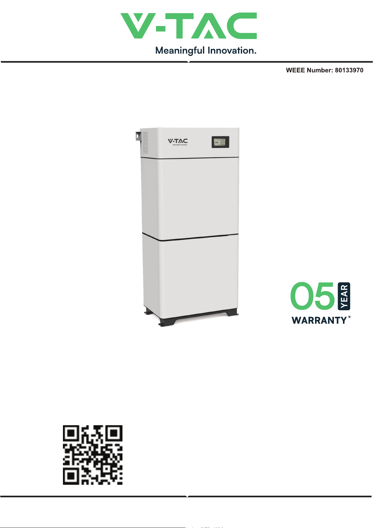
ESS SERIES BATTERY PACK
IN CASE OF ANY QUERY/ISSUE WITH THE PRODUCT, PLEASE REACH OUT TO US AT: SUPPORT@V-TAC.EU
FOR MORE PRODUCTS RANGE, INQUIRY PLEASE CONTACT OUR DISTRIBUTOR OR NEAREST
DEALERS. V-TAC EUROPE LTD. BULGARIA, PLOVDIV 4000, BUL.L.KARAVELOW 9B
Thank you for selecting and buying V-TAC Product. V-TAC will serve you
the best. Please read these instructions carefully & keep this user manual
handy for future reference. If you have any another query, please contact
our dealer or local vendor from whom you have purchased the product.
They are trained and ready to serve you at the best.
INTRODUCTION
Multi-Language Manual QR CODE
Please scan the QR code to access the manual
in multiple languages.
About This Document
Intended Audience
This document is intended for:
Hardware installation engineers
Technical support engineers
Maintenance engineers
Users
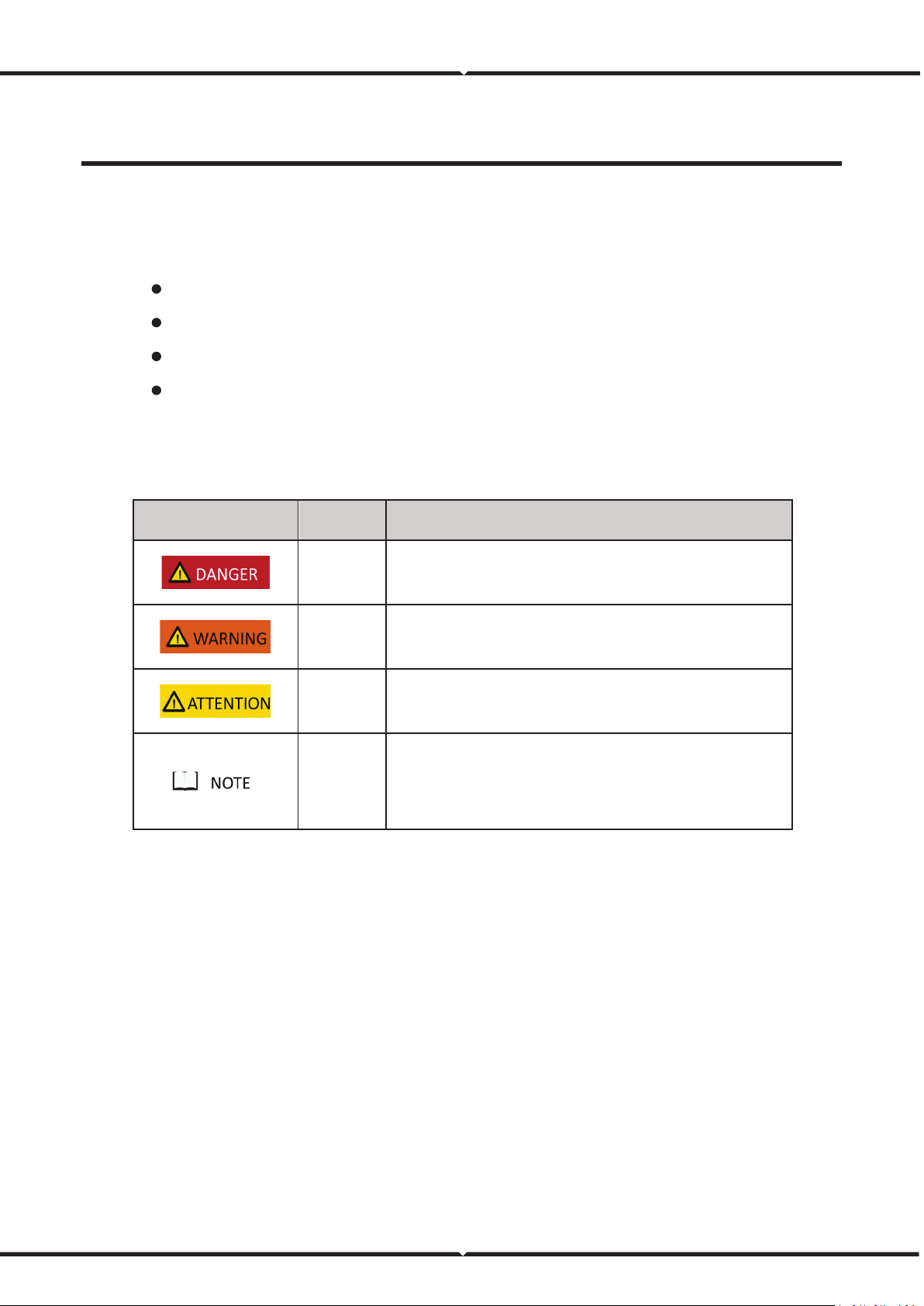
Symbol Conventions
The symbols that may be found in this document are defined as follows.
Symbol Definition Remarks
Danger
Indicates a hazard with a high level of risk which, if not avoided, will
result in death or serious injury.
Warning
Indicates a hazard with a medium level of risk which, if not avoided,
could result in death or serious injury.
Attention
Indicates a hazard with a low level of risk which, if not avoided,
could result in minor or moderate injury.
Note
Supplements the important information in the main text.
NOTE is used to address information not related to personal injury,
equipment damage, and environmental deterioration.
2 Overview
2.1 Product Application
RESS is a next-generation product developed by V-TAC, which is used in residential energy storage solut
ions. This battery system has a capacity of 19.2 kWh or 20.48 kWh.
RESS integrates the high-performance BMS. To extend battery life, it has multiple protection functions
such as system over-charge, system over-discharge, cell over-voltage, cell under-voltage, charging over-
current, discharging over-current, and insulation fault. It also has RS485, CAN, and dry contact
communication, allowing for remote monitoring.
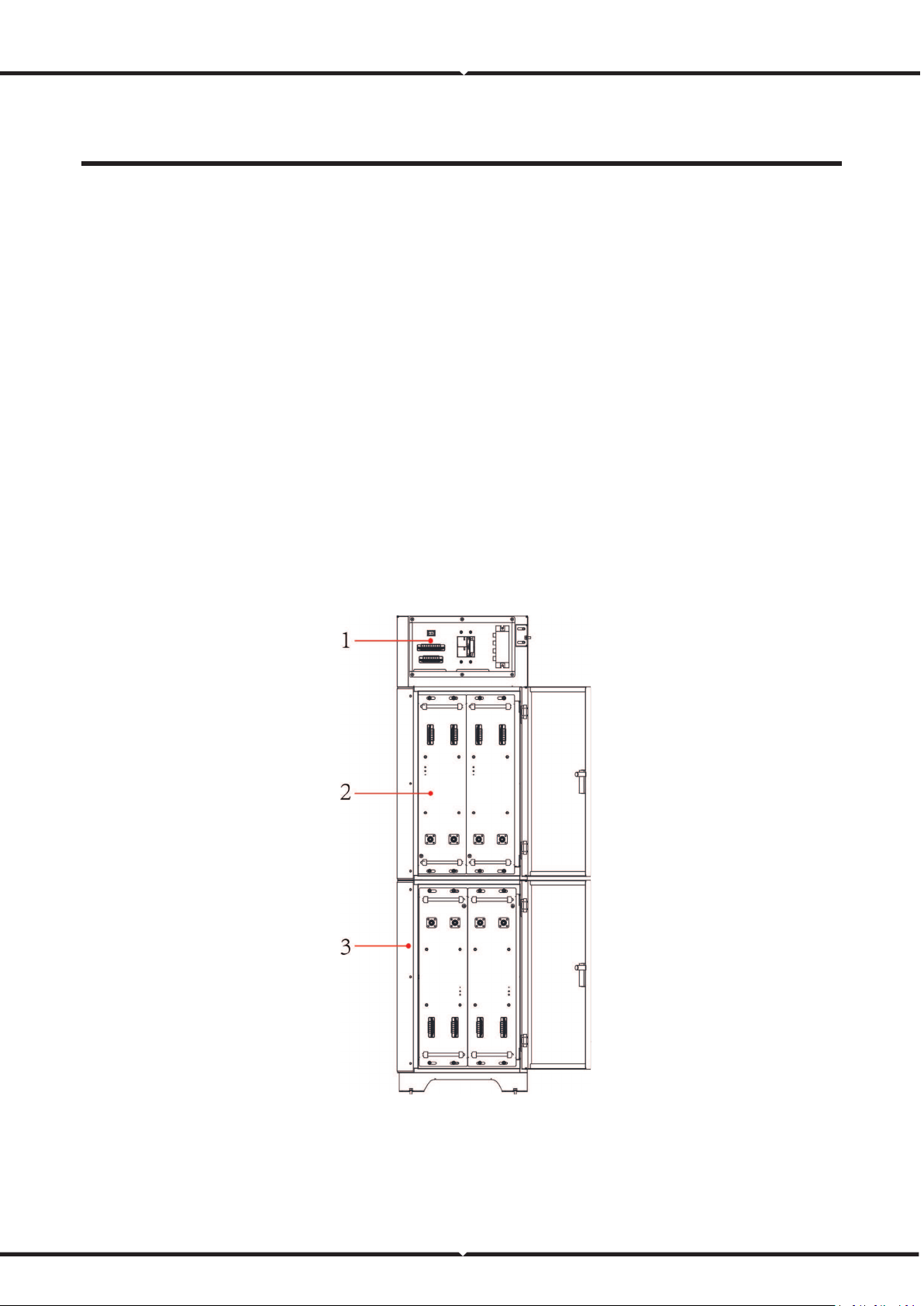
2.2 Product Composition
The RESS consists of one battery cabinet (two battery boxes and one chassis base inside), one high-
voltage box, and four battery modules.
The composition of the RESS is shown as follows:
Figure 1. RESS composition
(1) High-voltage box (2) Battery module (3) Battery cabinet
6
3 Components Introduction
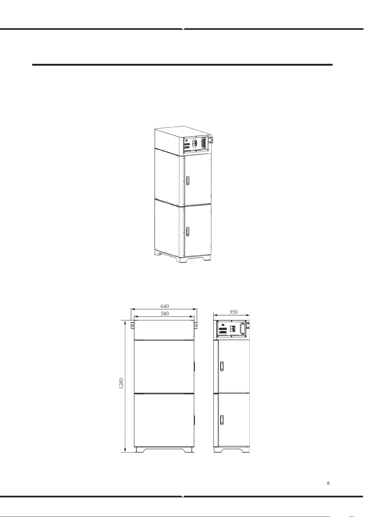
3.1 Battery Cabinet
The appearance of the battery cabinet is shown as follows.
Figure 2. Battery cabinet appearance
The battery cabinet dimensions are shown as follows:
Figure 3. Battery cabinet dimensions (unit: mm)

7
3.2 Battery System
The battery system specifications are as follows.
Table 1. Battery system specifications
No. Items Parameter Remark
1 Rated voltage
VEH192100C: 192 V
VEH204100C: 204.8 V
2 Rated capacity 100 Ah
3 Rated energy
VEH192100C: 19.2 kWh
VEH204100C: 20.48 kWh
4 System efficiency 92% Watt-hour efficiency
5 Communication type
CAN、RS485、DO/DI
6 Equalization Negative equalization ≤300 mA
7 Operation voltage range
VEH192100C: 168 V-204 V
VEH204100C: 179.2 V-217.6 V
8 Self-discharge ≤3% per month
9
Max continuous charge
current
100 A
10
Max continuous discharge
current
100 A
11 Total voltage sampling 0 V-600 V ±(0.5%FS+0.1%RD)
12 Total current sampling 1 A-200 A
13 Temperature sampling
NTC (-20℃~125℃) ±2℃
14 Insulation sampling
0~5MΩ
15 SOC estimate accuracy ≤8%
16 Charge ambient temperature
0℃-45℃
Optimum ambient
temperature: 15℃-
35℃
17
Discharge ambient
temperature
-10℃-45℃
18 Storage temperature
0℃-40℃
Copyright © Vestwoods Technology Co., Ltd. 8
No. Items Parameter Remark
19 Humidity 5%-95% RH, no condense
20 Protection
System over-voltage and system under-voltage, cell
over-voltage and cell under voltage, charging over-
current and discharging over-current, charging high
temperature and charging low temperature,
discharging high temperature and discharging low
temperature, short circuit protection, insulation
faulty protection
21 Dimensions (W×H×D) 640 mm×1280 mm×350 mm
22 Weight
VEH192100C: Approx. 230kg
VEH204100C: Approx. 238kg
3.2.1 Lithium-ion Cell
The lithium iron phosphate cell selected in the scheme is a special energy-type lithium battery product.
This series of lithium iron phosphate cells have high specific energy, longer cycle life, low cost, capable of
high current charge and discharge, high-temperature tolerance, high energy density, no battery memory
effect, safety, and pollution-free features.
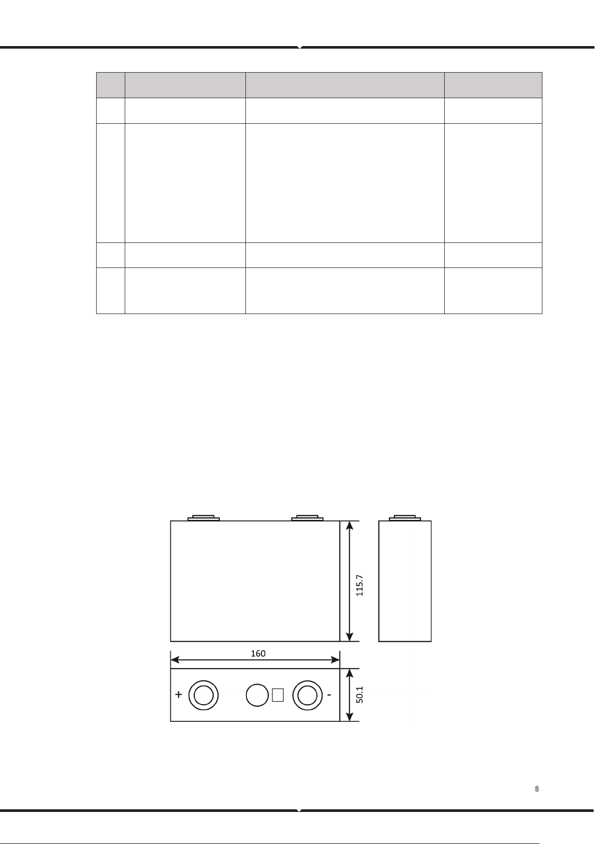
3.2.1.1 Appearance
Lithium-ion cell's three views are shown as follows.
Figure 4. Lithium-ion cell three views (unit: mm)

9
3.2.1.2 Technical Specifications
Lithium-ion cell main technical specifications are shown as follows.
Table 2. Lithium-ion cell main technical specifications
No. Items Specification
1 Battery type Lithium iron phosphate
2 Model LF100MA
3 Rated voltage 3.2 V
4 Rated capacity 100 Ah
5 Rated energy 0.32 kWh
6 Max continuous charge current 100 A
7 Max continuous discharge current 100 A
8 Charging cut-off voltage 3.65 V
9 Discharging cut-off voltage 2.50 V
10 Operating charging temperature
0℃-55℃
11 Operating discharging temperature
-20℃-45℃
12 Storage temperature
-20-45℃(less than 1 month);
0-35℃(less than 12 months);
13 Operating humidity 5%-95% RH
14 Cycle life
≥3500 cycle@ 25℃ 80%DOD
15 Size (Width*High*Depth) 160 mm×115.7 mm×50.1 mm
16 Weight About 1.92 kg
3.2.2 Battery Module
15 or 16 lithium cells are packed in the battery module, assembled in a combination of 1 parallel, 15, or
16 series.
The battery module is integrated with BMU to collect voltage and temperature and monitor the battery
module's status at all times.
10
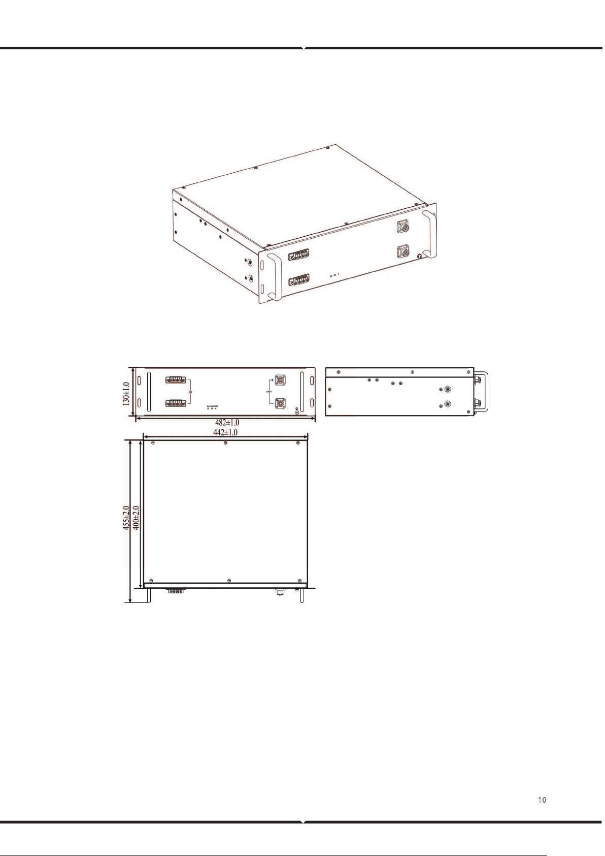
3.2.2.1 Appearance
The battery module appearance is shown as follows.
Figure 5. Battery module appearance
The battery module's three views are shown as follows.
Figure 6. Battery module three views (unit: mm)
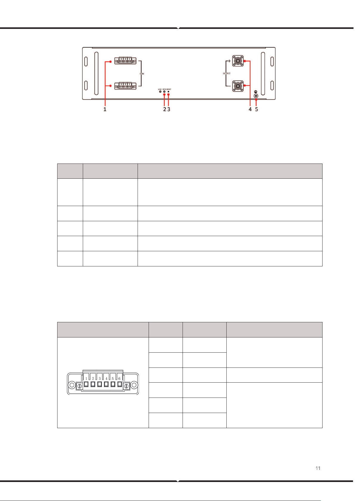
3.2.2.2 Operation Panel
The battery module operation panel is shown as follows.
11
Figure 7. Battery module operation panel
The definition of the battery module operation panel is shown as follows.
Table 3. Operation panel definition
No. Items Remark
1 Communication port
Communicate with other battery modules;
Communicate with high-voltage box.
2 Running indicator Indicate battery module running status.
3 Reset switch Reset BMU.
4 Output connectors Battery module output connectors.
5 Ground Ground.
3.2.2.3 PIN Definition
The PIN definition of a communication port is shown as follows.
Table 4. Communication port PIN definition
Location schematic diagram Location Definition Remark
1 24 V+
BMU power supply
2 24 V-
3 - -
4 CAN0H
Communication between BMU and BCU.
5 CAN0L
6 CAN0S
3.2.2.4 Technical Specifications
Copyright © Vestwoods Technology Co., Ltd. 12
The battery module's main technical specifications are shown as follows.
Table 5. Battery module main technical specifications
No. Items VT48100E-H1 VT48100E-H2
1 Model VT48100E-H1 VT48100E-H2
2 The number of cells 15 16
3 Cells in series and parallel 1P15S 1P16S
4 Model 48 V 51.2 V
5 Rated voltage 100 Ah 100 Ah
6 Rated capacity 4.80 kWh 5.12 kWh
7 Charging cut-off voltage 54.0 V 57.6 V
8 Discharging cut-off voltage 37.5 V 40.0 V
9 Max continuous charge current 100 A 100 A
10 Max continuous discharge current 100 A 100 A
11
Size (Width*High*Depth) 482 mm×130 mm×455 mm (With
the handle)
482 mm×130 mm×455 mm (With
the handle)
12 Weight About 39 kg About 41 kg
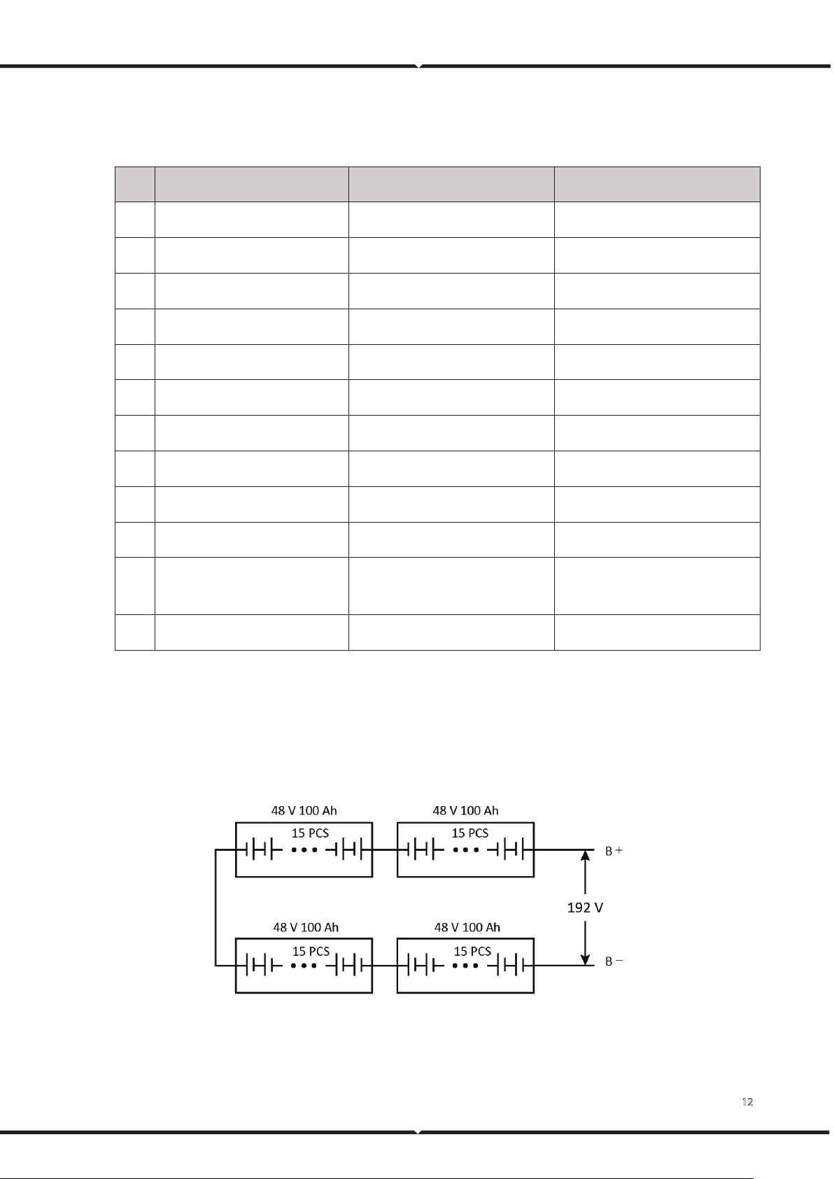
3.2.3 Battery Cluster
The battery cluster is composed of 4 battery modules. The schematic diagrams of battery clusters are
shown as follows.
Figure 8. VEH192100C battery cluster composition diagram
Copyright © Vestwoods Technology Co., Ltd. 13
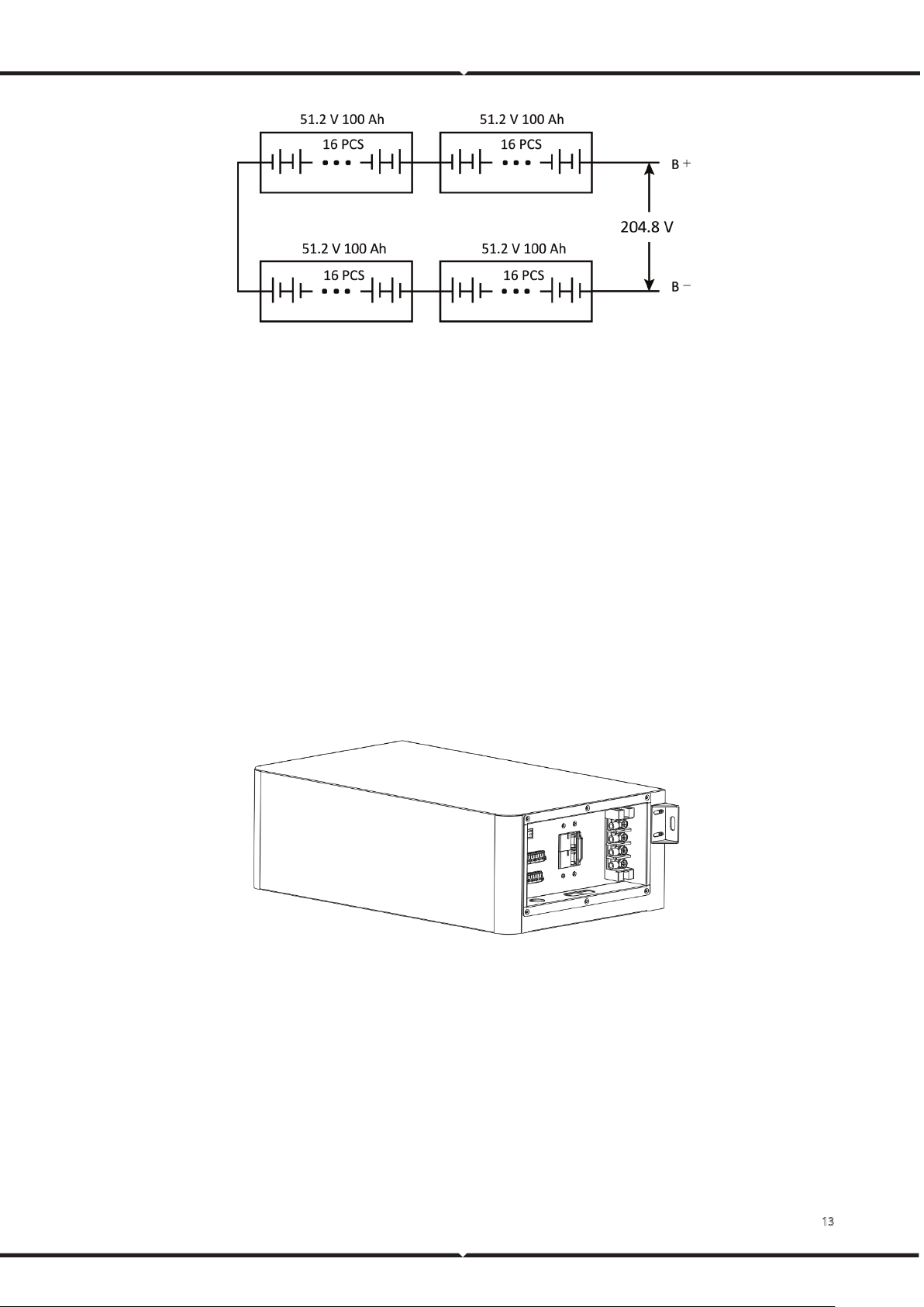
Figure 9. VEH204100C battery cluster composition diagram
3.2.4 High-Voltage Box
The high-voltage box is used to control and protect the DC connection or disconnection of the battery
cluster and communicate with the inverter.
If there are multiple battery cabinets in parallel, the appearance of the master and slave high-voltage
boxes is the same, but the functions are different. There is a PCU inside the master high-voltage box, and
there is no PCU inside the slave high-voltage box.
3.2.4.1 Appearance
The appearance of the high-voltage box is shown as follows.
Figure 10. High-voltage box appearance
The high-voltage box's three views are shown as follows.
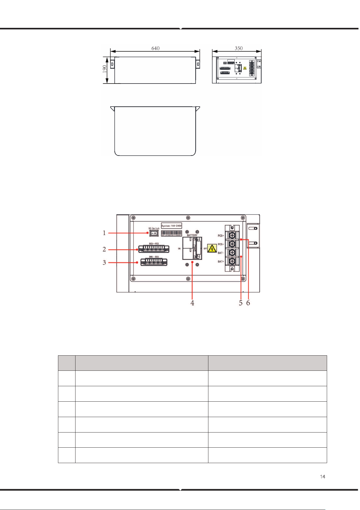
14
Figure 11. High-voltage box three views (unit: mm)
3.2.4.2 Operation Panel
The operation panel of the high-voltage box is shown as follows.
Figure 12. High-voltage box operation panel
The definition of the high-voltage box operation panel is shown as follows.
Table 6. Operation panel definition
No. Items Remark
1 DC input switch BMS 24V power supply control
2 External communication port (Master high voltage box) SCADA communication / Inverter communication
3 BMU communication port BMU power supply and communication
4 Output switch Battery output control
5 Battery input connectors Battery input connectors
6 Output connectors Battery output connectors
15
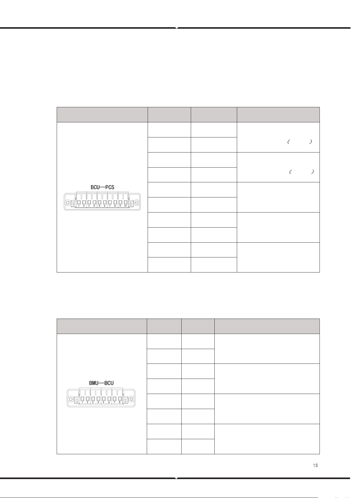
3.2.4.3 PIN Definition
External communication port
The PIN definition of an external communication port is shown as follows.
Table 7. External communication port PIN definition
Location schematic diagram Location Definition Remark
1 CAN1H
BCU communication, connect the
last high voltage box
(
Optional
)
2 CAN1L
3 CAN1H
BCU communication, connect the
next high voltage box
(
Optional
)
4 CAN1L
5 CAN2H
Inverter communication
6 CAN2L
7 DI+
Low voltage wake up
8 DI-
9 AC/L
AC input
10 AC/N
BMU communication port
The PIN definition of the BMU communication port is shown as follows.
Table 8. BMU communication port PIN definition
Location schematic diagram Location Definition Remark
1 V+
Battery module 24V power supply
2 V-
3 CAN0H
BMU communication, connect the last
battery module
4 CAN0L
5 V+
Battery module 24V power supply
6 V-
7 CAN0H
BMU communication, connect the next
battery module
8 CAN0L

16
3.2.4.4 Technical Specifications
High-voltage box main technical specifications are shown as follows.
Table 9. High-voltage box main technical specifications
No. Items Specification Remark
1 Rated voltage 300 VDC
2 Rated current 100 A
3 Power supply
Dual power redundant power supply: battery module
power supply, inverter power supply
4 Power consumption
<40 W
5 Communication type CAN*3
6 Cooling type Natural cooling
7 Total voltage sampling 0 V~600 V ±(0.5%FS+0.1%RD)
8 Total current sampling 1 A~200 A
9 Temperature sampling
NTC (-20℃~125℃) ±2℃
10 Insulation
0~5MΩ
11 Short circuit protect Yes, fuse
12 Isolation rate
500 VDC, the 60s, isolation resistance of more than
10 MΩ
13 Dielectric strength 1500 VAC, the 60s, No flashover, and breakthrough
14 Ambient temperature
0℃-45℃
Recommended
temperature: 25℃-35℃
15 Operation humidity 5%-95%RH and no condense
16 Size (Width*High*Depth) 640 mm×190 mm×350 mm
17 Weight 14.5 kg
3.3 Battery Management System
RESS adopts the battery management system (BMS) developed by Vestwoods, including the following
three-layer structural units:
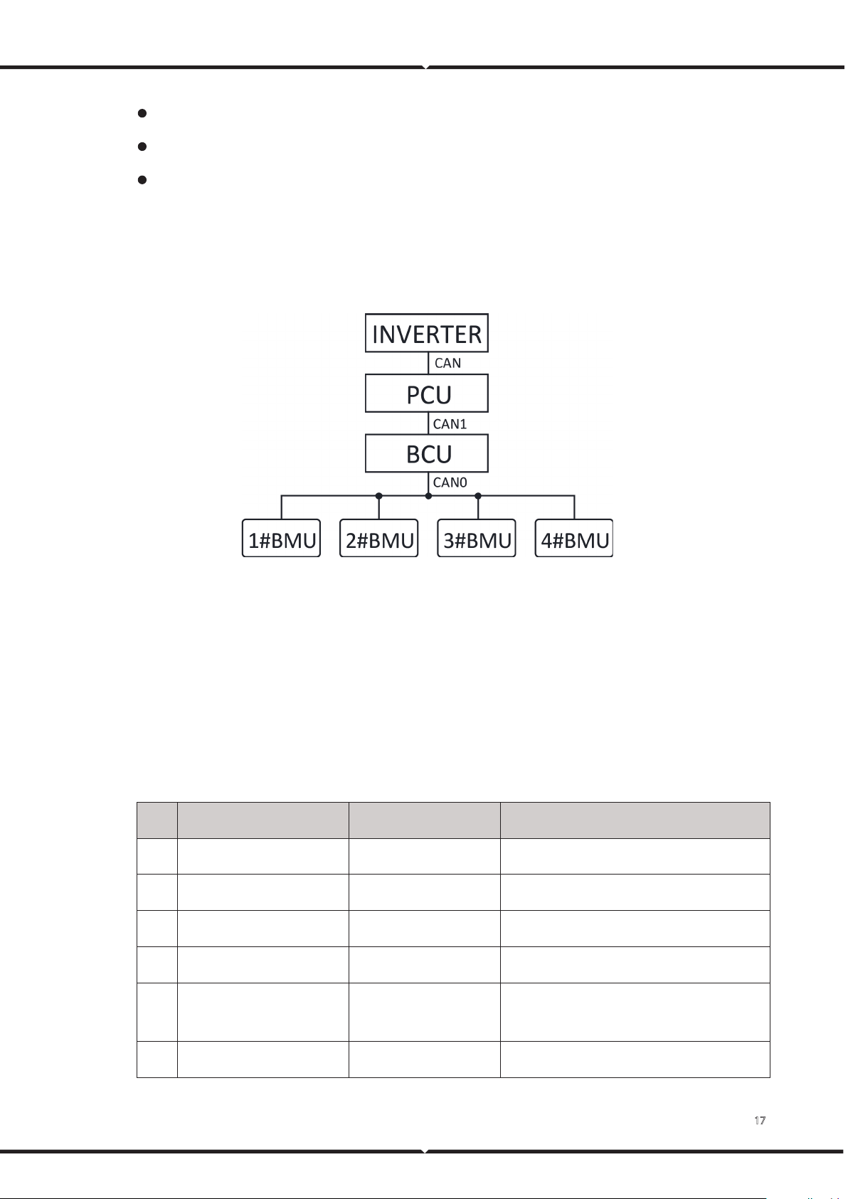
17
Battery module management module: BMU, integrated with the battery module.
Battery cluster management module: BCU, integrated with the high voltage box.
Battery system management module: PCU, integrated with the high voltage box.
BMS can monitor the current, voltage, and temperature of cells in the battery module in real-time,
calculate the SOC of the battery system, communicate with the host computer software, and send fault
and alarm information.
The schematic diagram of the communication structure of the BMS is shown as follows.
Figure 13. Communication topology
3.3.1 BMU
The BMU integrated with the battery module is the initiating unit of the BMS. It monitors battery
voltage and temperature and transmits cell information to the BCU through the communication port.
BMU's main technical specifications are shown as follows.
Table 10. BMU main technical specifications
No. Item Specification Remark
1 Power supply 24 VDC
2 Power consumption
<1 W
Without equalization
3 Voltage sampling channels 15 strings Compatible with 16 strings
4 Voltage sampling range
0 V~5 V
Accuracy ±10 mV
5
Temperature sampling
channel
4 cell sampling and 1 PCB
sampling
6 Temperature sampling range
-20℃~125℃ Accuracy ±2℃

18
No. Item Specification Remark
7 Equalization Negative equalization ≤ 300 mA
8 Operation temperature
-20℃~75℃
9 Operation humidity 5%-95%RH
3.3.2 BCU
The BCU integrated with the high-voltage box is the intermediate level of the BMS. It collects information
from the BMU and transmits it to the PCU.
BCU can effectively manage the safety of charge and discharge of battery clusters, provide real-time
monitoring of battery parameters, fault diagnosis, SOC/SOH estimation, insulation detection, remote
monitoring, and other functions, and trigger protection when alarm and emergency battery module
possible failures appear, to ensure the safety, reliable and stable operation of battery modules.
BCU's main technical specifications are shown as follows.
Table 11. BCU main technical specifications
No. Item Specification Remark
1 Power supply 24 VDC
2 Power consumption
<2 W
3 Total voltage sampling 0 V~600 V ±(0.5%FS+0.1%RD)
4 Current sampling 0 A~1000 A ±(0.5%FS+0.5%RD)
5 Temperature sampling
2 Channels, -20℃-125℃ Accuracy ±2℃
6 DO 8 channels
7 DI 8 channels
8 Insulation 0~5 MΩ
Total voltage≥400 V, accuracy ±20%;
Total voltage<400 V, accuracy ±30%;
Insulation resistance≤5kΩ, accuracy ±10kΩ
9 SOC estimate accuracy ≤8%
10 Communication type CAN-3 channels, RS485-2 channels
3.3.3 PCU

19
The PCU integrated with the high-voltage box can monitor and manage battery clusters internally and
complete information exchange externally.
The main functions of the PCU are as follows:
Battery information management: PCU can monitor cell voltage, cell temperature, cluster voltage,
cluster charging current, and cluster discharging current in real-time.
SOC estimation: Estimated the battery cluster SOC.
DI/ DO communication: PCU provides multiple DI and DO interfaces.
CAN and RS485 communication: PCU provides 3 CAN communication interfaces and 2 RS485
communication interfaces.
Self-fault diagnosis: PCU has a self-test function.
Charge and discharge management: PCU can coordinate the charge and discharge between battery
clusters and improve the circulating current in clusters.

Copyright © Vestwoods Technology Co., Ltd. 20
4 Installation Guide
4.1 Precautions for Installation
Light intensity is required near the installation location.
Comply with the safety operation technical regulations when lifting and handling heavy objects.
Equipment and tools must be complete, intact, and reliable. It is strictly prohibited to use tools with
cracks, burrs, loose handles, etc., that do not meet the safety Standards.
Installation operations must be guided by qualified engineers.
During installation, two people must work together, one operating and the other inspecting.
The original cable connection and operation process shall not change without the authorization of
the company's consent.
4.2 Preparing for Installation
4.2.1 Tools
Must be insulate installation tools to prevent electric shocks. If tools without insulation protection are
used, may the exposed metal parts need to be wrapped and insulated with insulating tape.
The following table shows the tools that need to be prepared before installation.
Table 12. Tools
Electric screwdriver Manual forklift Impact drill Socket wrench
Tape measure Adjustable wrench Torque wrench Claw hammer
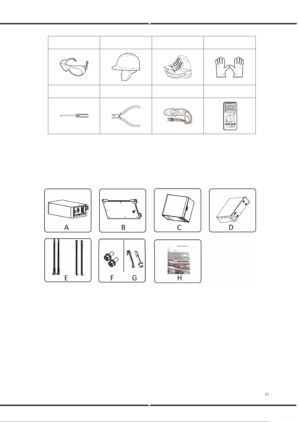
21
Goggle Helmet Insulation shoes Anti-static gloves
Phillips screwdriver Diagonal pliers Clamp meter Multimeter
4.2.2 Packing List
Open the package and take out the product, please check the accessories first. The packing list is shown
below.
Figure 14. Accessories of RESS
A High-voltage box B Base C Battery box*2 (optional)
D Battery*4 (optional) E Wire rod F/G Expansion screws and hexagonal screw
H User manual
Copyright © Vestwoods Technology Co., Ltd. 22
4.2.3 Unpacking Acceptance
After receiving the goods on-site, please check whether the packing box is intact and inspect the goods
in time. If the packing box is slightly damaged, please sign and confirm the goods list and indicate the
extent of the damage. If the damage is severe, please refuse to sign.
Please carry out an unpacking inspection after receiving all the goods. If users find that the received
goods do not match the packing list, please contact Vestwoods as soon as possible.
4.3 Installing Battery Cabinet
Context
Before installing the battery cabinet, users need to plan the installation site. The installation site should
comply with the following conditions:
The installation site should be able to place one battery cabinet, and there should be a wall to
mount the inverter.
A 500 mm ventilation and operation space should be reserved at the right of the battery cabinet.
If possible, the installation site should be as spacious and ventilated as possible. If the site is small
and confined, please configure auxiliary heat dissipation equipment.
Procedure
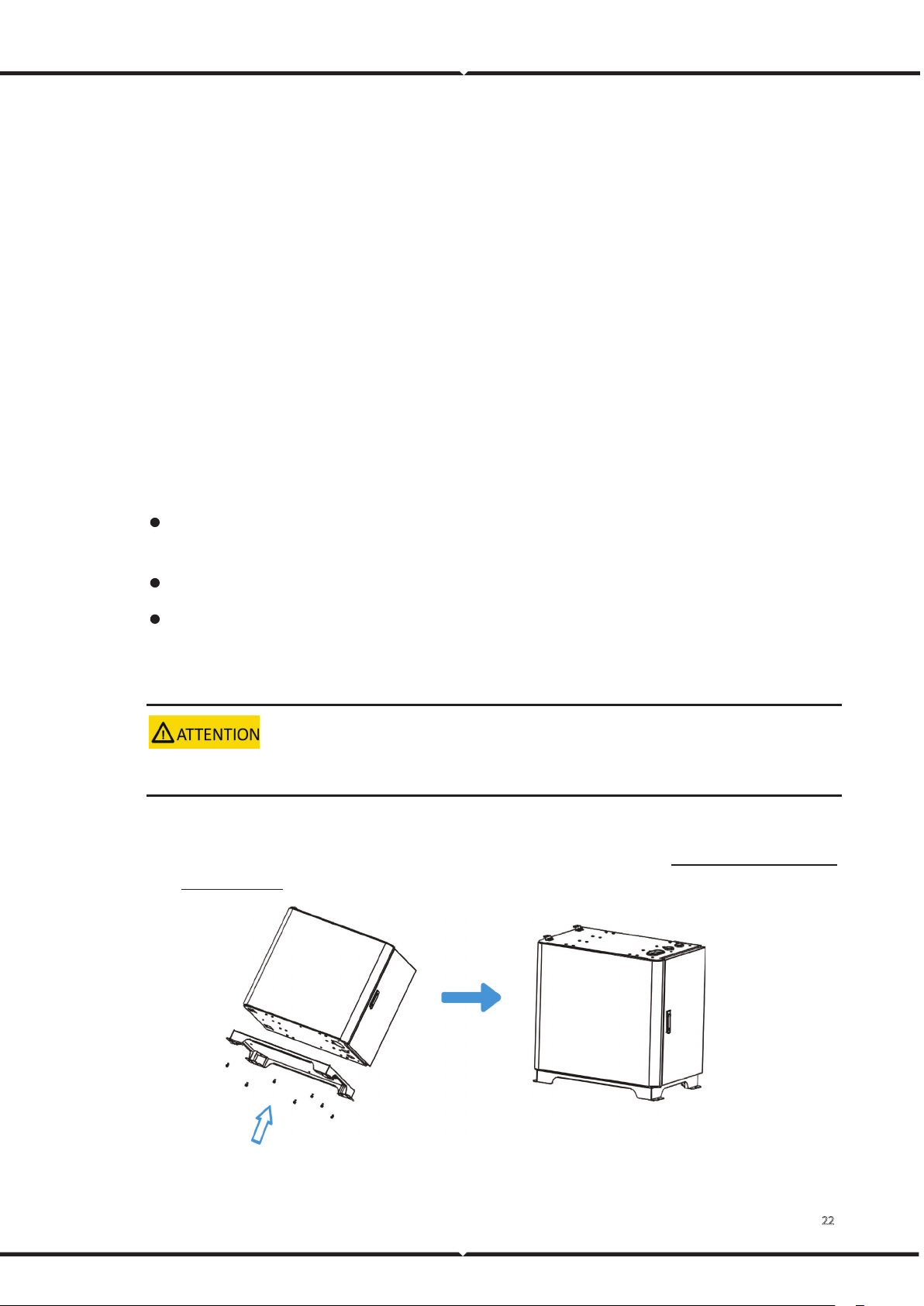
The battery cabinet is heavy. If possible, please use tools to assist in handling and installation.
1 Plan the installation position of the battery cabinet according to the actual situation of the site.
2 Fixing the chassis base with the battery box 1, using 8 pcs M5*12 screws. (It has been pre-installed
before delivery)
Figure 15. Fixing the chassis base of the battery box
23
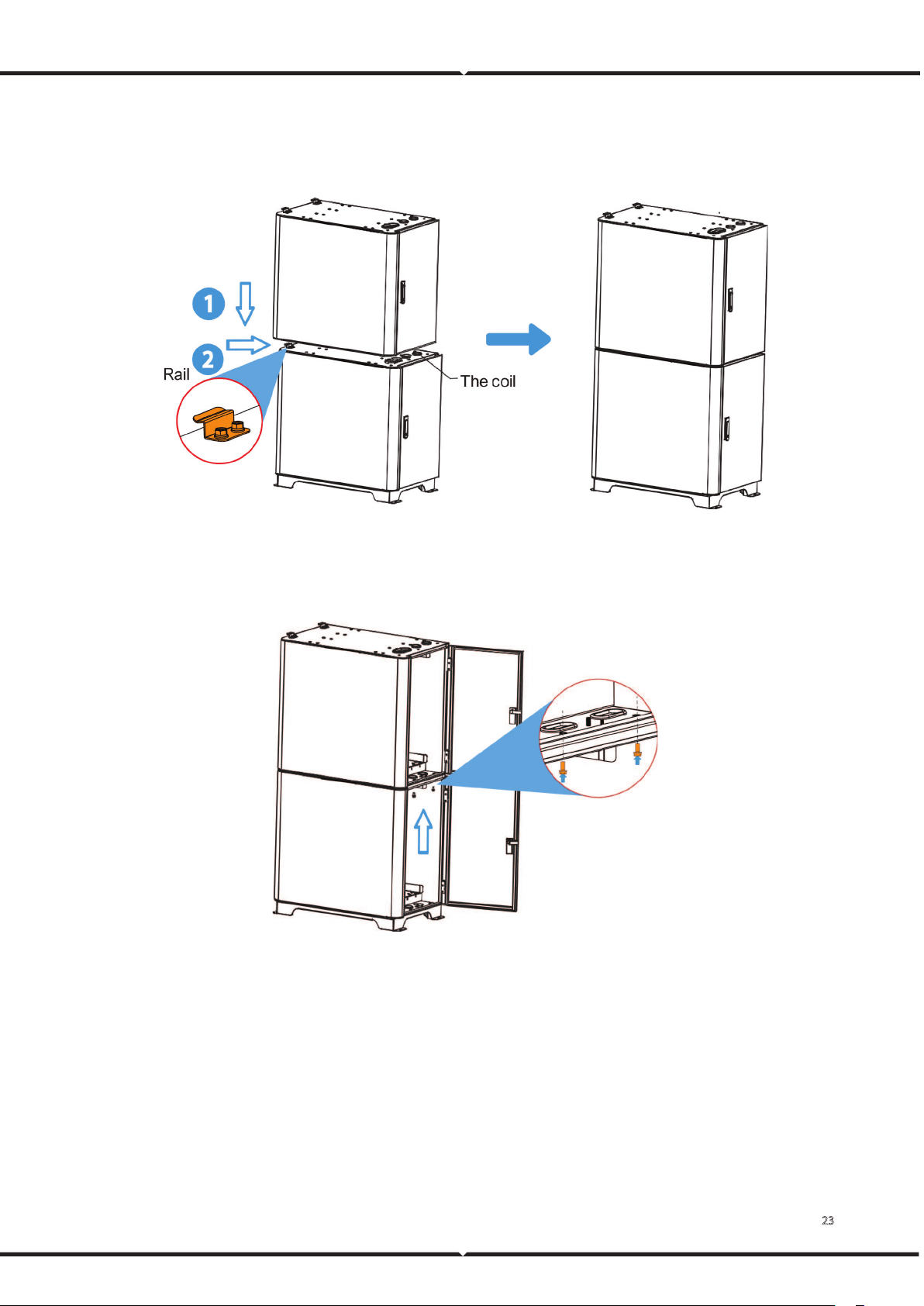
3 The battery box 2 fixing. Install 2 pcs guide rails of battery box 1 first, then align the lower notch of
battery box 2 with the upper guide of battery box 1, lower it and push it to the right. Facilitate
pushing to the right, the coil can be removed before assembly.
Figure 16. Fixing the battery box 2
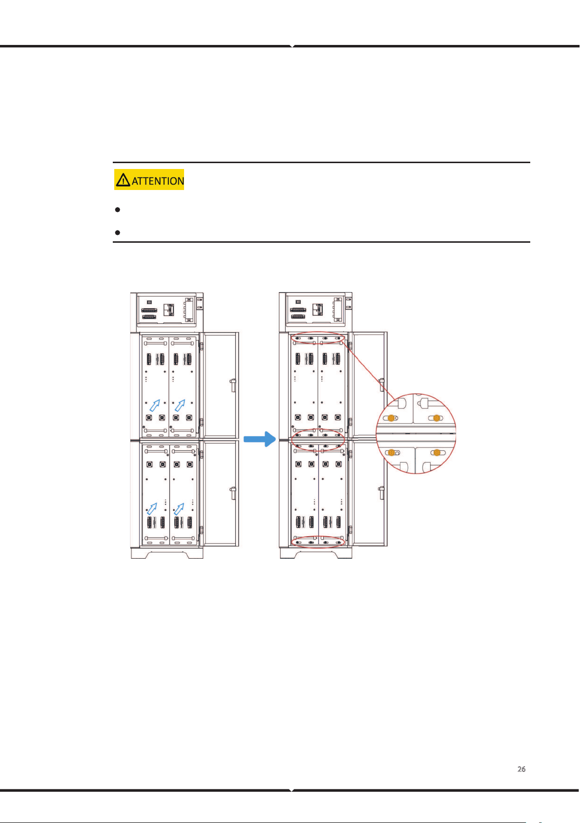
4 Two sets of battery cabinets are fixed, install 2 pcs guide rails of battery box 2, then open the
battery cabinet doors, and use 2 pcs M5*12 screws to fix it upward.
Figure 17. Fixing the battery cabinet
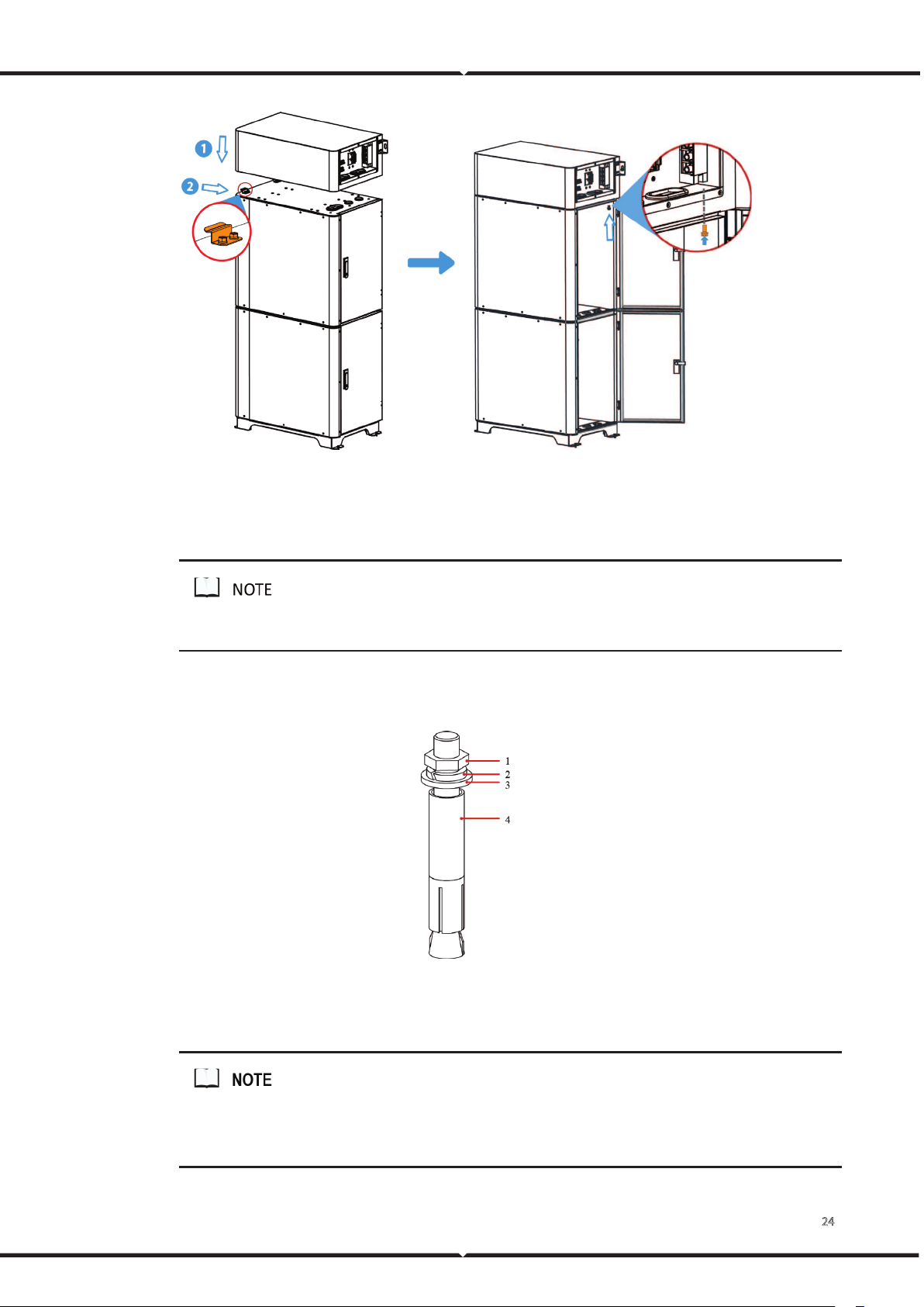
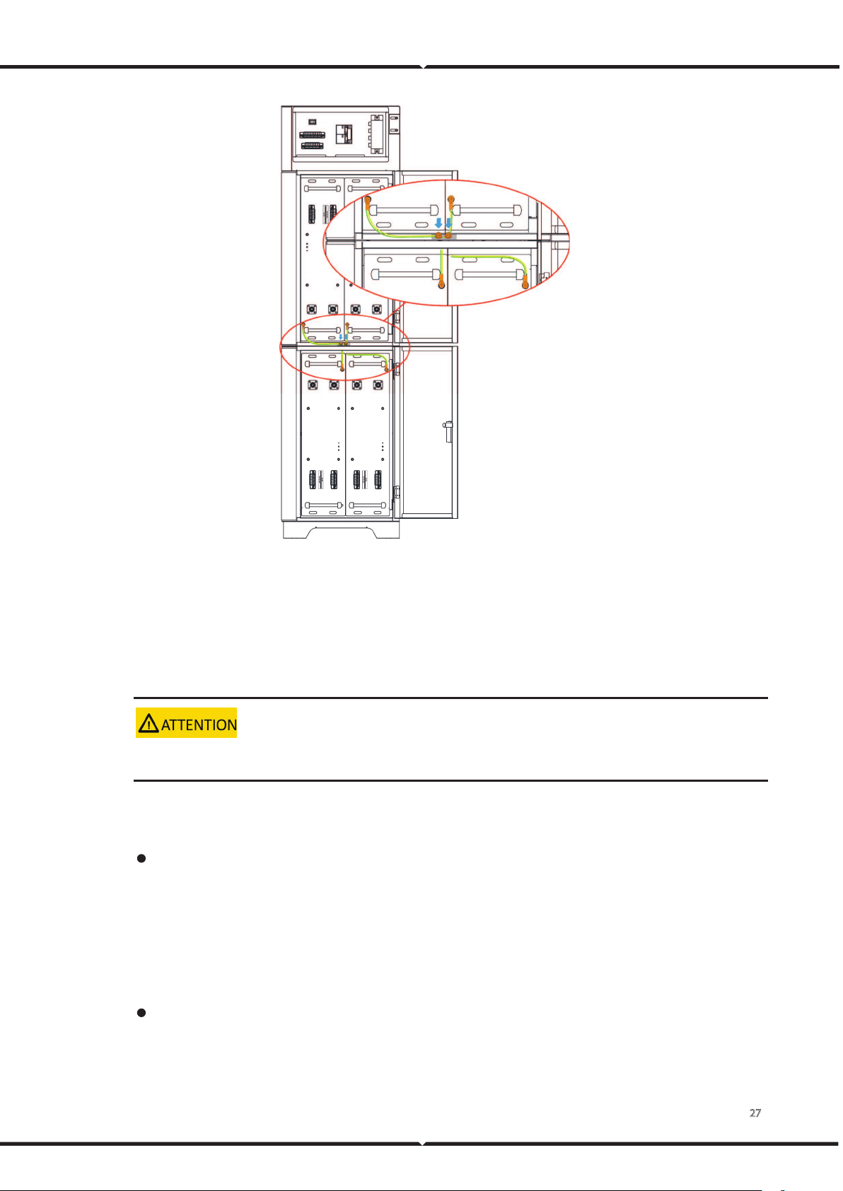
5 Fixing of high-voltage box. The method is the same as step 3 & step 4. To facilitate pushing to the
right, the coil can be removed before assembly.
24
Figure 18. Fixing the high-voltage box
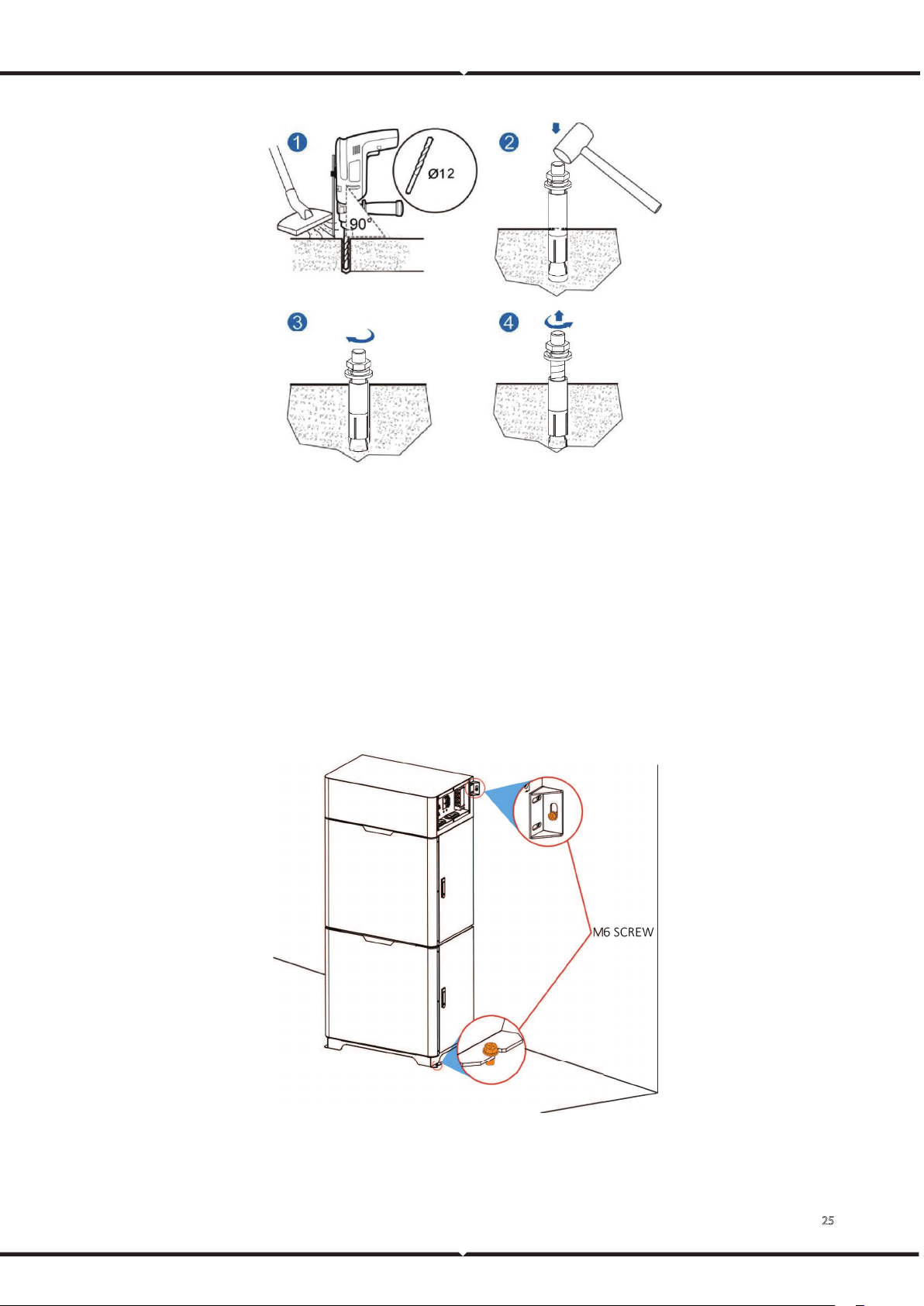
6 Whole machine fixing, drill holes according to the position of the battery cabinet installation holes.
The top is fixed to the wall, and the bottom is fixed to the ground, using M6 Expansion screws.
If the battery cabinet is installed against the wall, it can be fixed on the wall.
7 Use a hammer drill to drill holes for installing the expansion bolts and then install the expansion
sleeves in the holes.
Figure 19. Expansion bolt composition
(2) M10 bolt (2) Spring washer (3) Flat washer (4) Expansion sleeve
Ensure the expansion tube of the expansion bolts fits completely into the hole. The expansion sleeves must be
completely buried under the ground to properly facilitate subsequent installation.
25
Figure 20. Installing expansion bolts (unit: mm)
A Drill holes in the ground by using a hammer drill.
B Partially tighten the expansion bolt and vertically insert it into the hole. Hit the expansion bolt
using a hammer until the expansion sleeve is fully inserted into the hole.
C Partially tighten the expansion bolt.
D Remove the bolt, spring washer, and flat washer.
8 Place the cabinet in the installation location. Use M10×90 expansion bolts to fix the expansion
holes of the m
aster cabinet and slave cabinets to the ground.
Figure 21. Location of the mounting holes (unit: mm)
26
4.4 Installing Battery Module
Procedure
1 Take out the battery module and put it in the installation place.
The battery module is heavy. If possible, please use tools to assist in handling and installation.
The address of the battery module can be automatically assigned after the battery module is powered on.
2 Fixing the battery modules to the cabinet with the cross-recessed pan head combination screws. A
total of 16 pcs M5*12 screws are used.
Figure 22. Installing battery module
3 Use ground cables to connect the battery module's ground point to the cabinet's ground point.
27
Figure 23. Battery module grounding
4.5 Connecting Power Cable
Context
Insulate installation tools to prevent electric shocks.
The battery module power cable connection method adopts the self-locking connector method. The
description of the self-locking connector is shown as follows:
The steps for connecting the self-locking connector are as follows:
A Adjust the direction of the self-locking connector to align with the battery module terminal.
B Rotate the self-locking connector slightly, and it will be sucked in automatically.
C After the self-locking connector is automatically sucked in, push it in slightly, and after hearing
a sound, the self-locking connector and the battery module terminal are connected.
Users need to press the buttons on the self-locking connector simultaneously when users need to
pull out the self-locking connector.
28
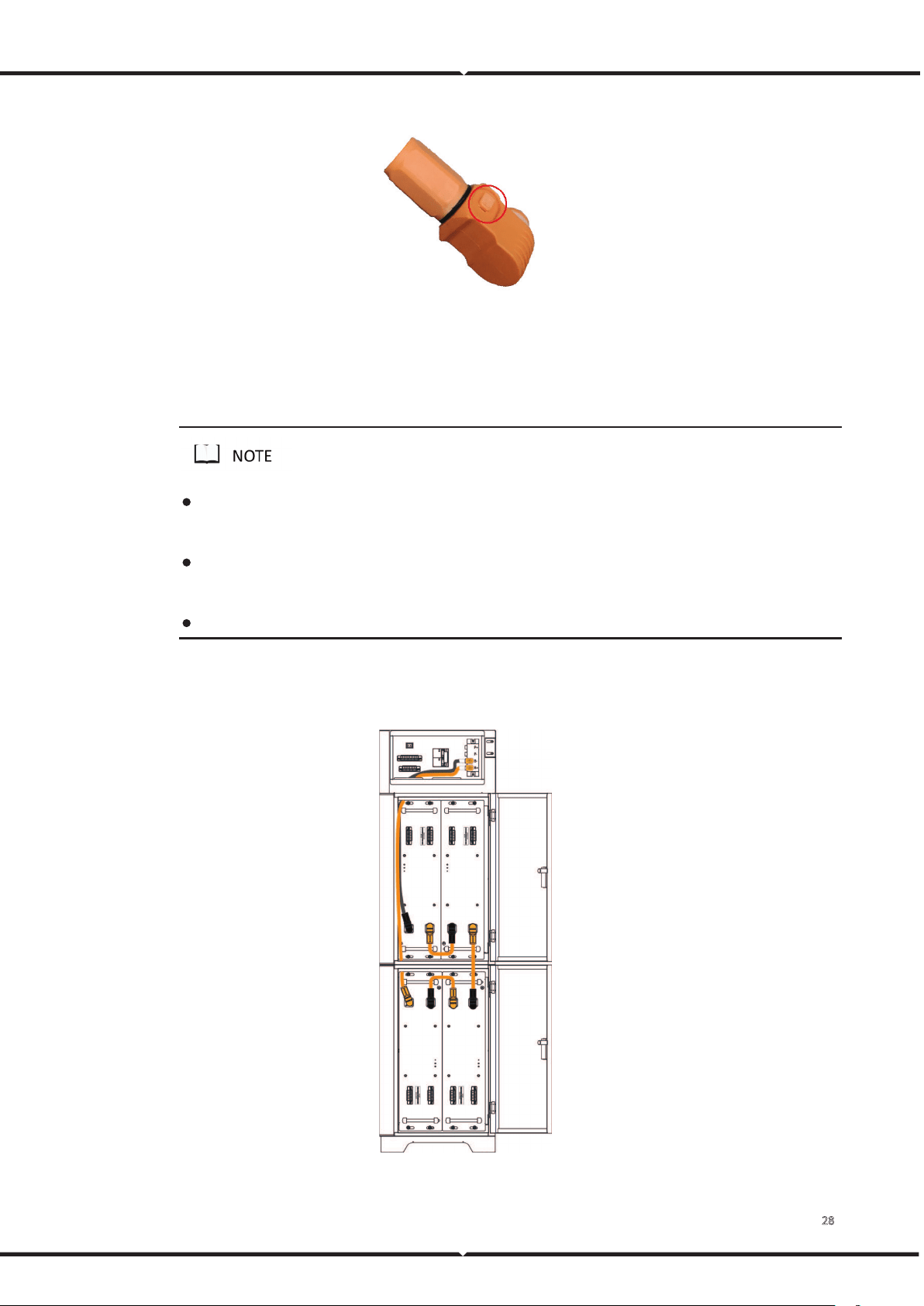
Figure 24. Self-locking connector button
Procedure
1 Connect the power cable between the high-voltage box and the battery module.
The self-locking connector's color should correspond to the battery module terminal's color: orange
corresponds to the positive pole, and black corresponds to the negative pole.
The internal wiring of the battery cabinet is the same. This chapter takes a battery cabinet as an example to
introduce.
Please take care of the removed battery module protective cover in case of backup.
2 Connect the power cable between the RESS battery modules.
The wiring diagram of the battery inside of the battery cabinet is as follows:
Figure 25. The wiring diagram of the inside of the battery cabinet
29
The wiring sequence is: first connect the OT terminal to the high-voltage box terminal, and then connect to the
battery modules. Please strictly follow the wiring sequence. Otherwise, it will be easy to short-circuit.
The self-locking connector's color should correspond to the battery module terminal's color: orange corresponds
to the positive pole, and black corresponds to the negative pole.
The bolt type on the high-voltage box terminal is M8, and the recommended tightening torque is 7 N.m.
4.6 Connecting Signal Cable
Context
Please pay attention to the direction when plugging the signal cable connector, do not operate violently.
Signal cables and power cables must be routed separately.
If there are multiple battery cabinets in parallel, there is a Host machine label on the master high-voltage
box and a Slave machine on the slave high-voltage box. Only the master high-voltage box needs to connect
the signal cable to the inverter. Please pay attention to the distinction.
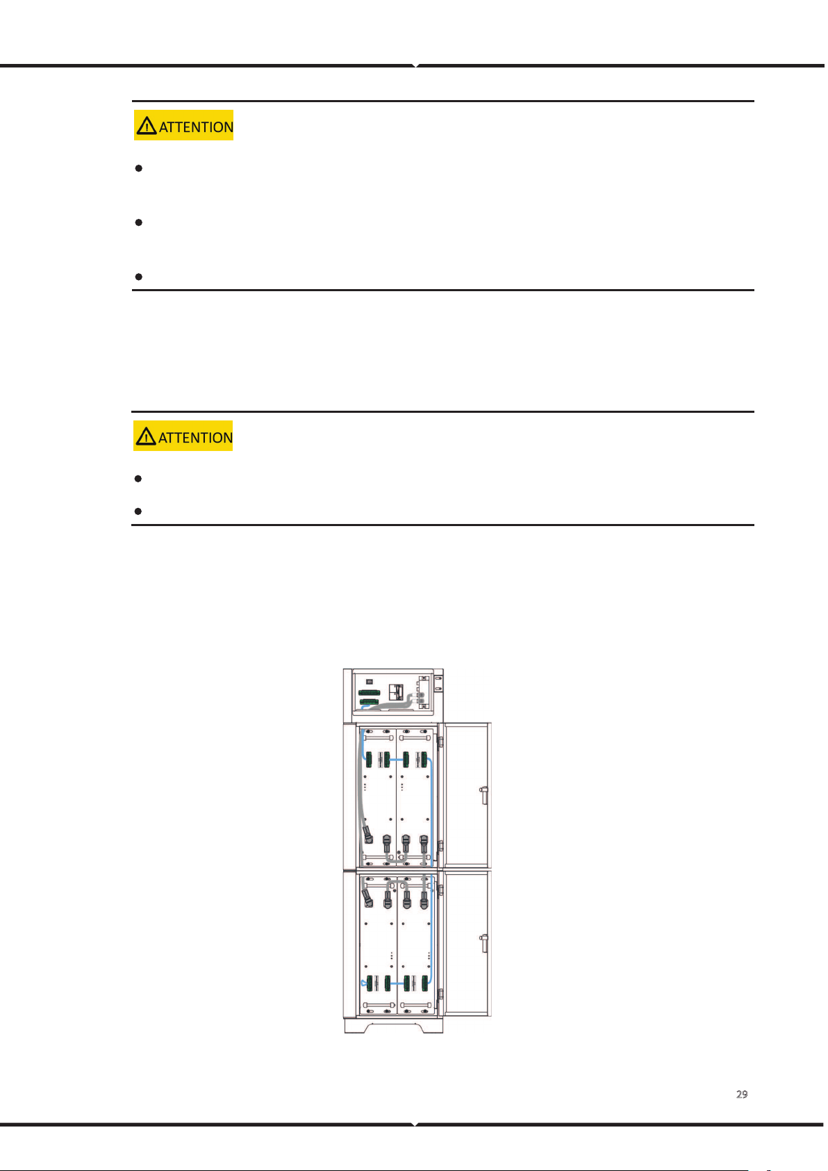
Procedure
1 Connect the internal signal cable of the RESS battery cabinet.
Figure 26. Connect the internal signal cable of the battery cabinet
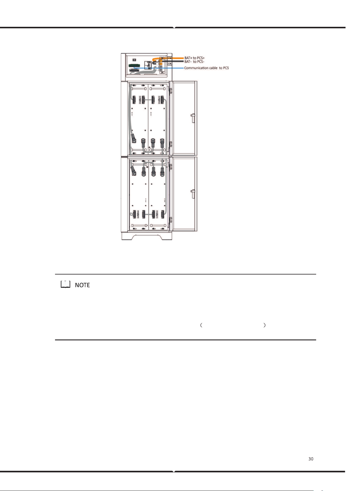
30
2 Connect the remaining power cables and signal cables between the battery cabinet and inverter.
Figure 27. Connect the external cables
3 For the wiring diagram of the inverter to the user side, please refer to the inverter user manual.
1. Please confirm the usage scenarios of the inverter according to the actual situation. For details, please refer to the
inverter user manual.
2. The communication cable to the inverter contains L&N cable
(
220V power supply for BMS). Please connect this
cable to the output port of the inverter. (Optional)

31
5 Operation Guide
5.1 Check before Power-on
Context
After installing the RESS, users need to perform a pre-power check to ensure that the device installation
and cable connection are correct before performing the power-on operation.
Procedure
1 Check whether the battery module sequence is consistent with the layout diagram.
2 Check the cable connection on site.
Check whether the cables are connected correctly, whether the connectors are firm, and
whether the self-locking connector is tightly connected.
Check whether the bolt torque on the terminal of the high-voltage box is 7 N.m.
Check whether the signal cable and the power cable are separated.
3 Check whether the battery module and high-voltage box are grounded.
4 Check the switch status.
The DC input switch and output switch of the high-voltage box are open.
The DC switch of the inverter is open.
The circuit breaker from the inverter to the grid is open.
5.2 Power-on
Context
Before performing the power-on commissioning on the RESS, users must strictly perform the pre-power-on check.
Procedure
1 Close the DC switch of the inverter.
2 Close the output switch of the high-voltage box.
3 Close the circuit breaker between the inverter and the grid.

32
5.3 Operation Guide
The battery system has completed the system parameter settings at the factory, and the system will run
automatically after power is on.
The inverter needs to be set according to actual needs. For detailed operations, please refer to the User
Manual.

33
6 Routing Maintenance
The engineering personnel who perform the following operations must have received professional training.
Before operating and maintaining the RESS, wear anti-static work clothes, anti-static gloves, and wrist straps, and
remove conductive objects such as jewelry and watches to avoid electric shock or burns.
All RESS internal maintenance work requires insulated tools and should be performed by personnel who have
received relevant training.
When operations such as installation and maintenance only involve the battery system, the output switch of the
high-voltage box should be kept open. When the inverter is involved, the DC input switch of the high-voltage box,
the output switch of the high-voltage box, the DC switch of the inverter, and the circuit breaker from the inverter
to the grid should be kept open.
6.1 Battery Storage
The recommended storage temperature is 15℃~35℃.
Battery performance degradation after long-term storage, please shorten shelf time as possible as
you can.
Recharge charge before using to recover capacity loss of self-discharge during storage and transport.
Storage battery should be at 40%-50%SOC when the battery is not used for a long time.
Storage batteries over 40°C or under 0°C will reduce battery life. A storage battery in a dry and low-
temperature, well-ventilated place.
If the battery is not used for a long time, the battery must be charged at regular intervals. The charging
requirements are as follows:
Table 13. Battery Charge Requirement in Storage Status
Storage Temp. Charge Period Charge Process
20℃~30℃
Each 6 months 1. Charge by 0.2C to 100% SOC
2. Discharge by 0.2C to 0% SOC
3. Charge by 0.2C to 40%~50% SOC
0℃~20℃ or 30℃~40℃
Each 3 months
6.2 Monthly Maintenance
34
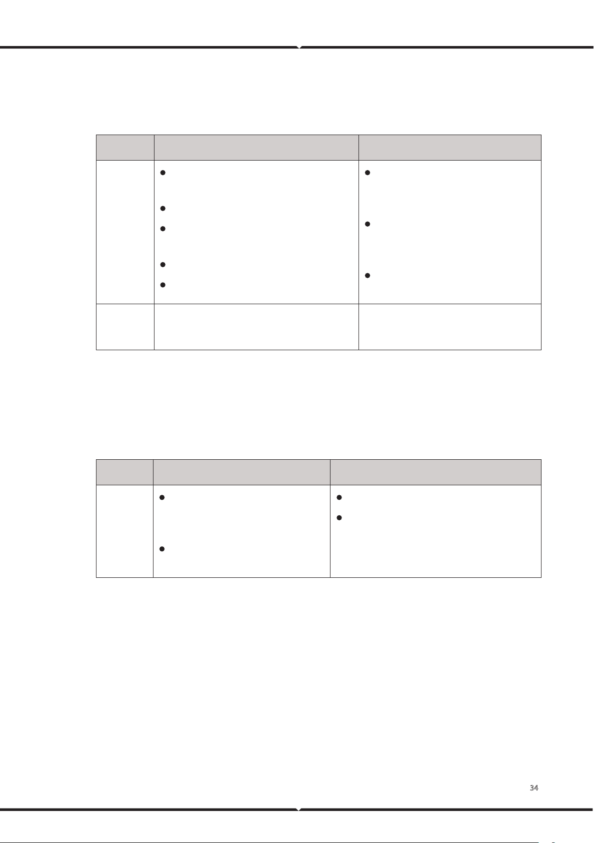
Users should conduct a visual inspection of the RESS monthly. Please refer to the following table for
monthly maintenance.
Table 14. Monthly maintenance
Item Refer Standard Abnormal Handling Suggestion
Battery
appearance
The appearance is neat and clean without
stains.
The battery terminals are intact.
The battery shell is intact, and there are no
bumps, breaks, or cracks around it.
The appearance of battery has no leakage.
There is no deformation or bulging of the shell.
If there is dirt on the surface, clean the
battery module's appearance with a
cotton cloth.
If the appearance is damaged, leaking, or
deformed, take a photo and replace the
problem battery module.
Please contact Vestwoods in time for
other abnormal situations.
Operation
environment
The operation environment is between 0℃-45℃.
Operation humidity range: ≤95% RH.
If temperature and humidity are abnormal,
check the indoor air conditioner status.
6.3 Quarterly Maintenance
Please refer to the following table for the quarterly maintenance of RESS.
Table 15. Quarterly maintenance
Item Refer Standard Abnormal Handling Suggestion
Cable
There is no aging of the connecting
wire and no cracking of the insulation
layer.
The bolts at the cable connection are
not loose.
Replace the faulty cable.
Fasten the screws.
6.4 Yearly Maintenance
It is recommended to perform trend analysis on recorded data (battery and environment).

35
Acronyms and Abbreviations
AC Alternating Current
BMU Battery Management unit
BMS Battery Management System
BCU Battery Control Unit
DC Direct Current
PCU Protocol Converter Unit
SOC State of Charge
SOH State of Health