
Hand-held Digital Insulaon Resistance
Tester User Manual
1. Overview
This series of meters are high performance hand-held digital
insulaon resistance testers. It has a safe structural design and a new
electronic circuit design with more complete funcons, higher
accuracy, and more convenient and reliable operaon. It is
shock-proof, dust-proof, moisture-proof, and is suitable for outdoor
use. A selecon of output test voltages from 100V/250V/500V/
1000V/2500V/5000V are available on dierent models, and the
highest insulaon resistance measurement range can reach up to
200. AC voltages can also be measured.
This product is suitable for measuring insulaon resistance of various
types of electrical equipment and insulaon materials such as
transformers, motors, cables, switches, and electrical appliances. It
can also be used for maintenance, tesng, and vericaon purposes
for various types of electrical equipment.
This series of meters are your ideal electrical tesng instruments.
2. Safety Rules
(1) Please read this user manual carefully before using;
(2) The design of this meter complies with the IEC-1010 double
insulaon, “polluon degree 2”, and Overvoltage Category II
safety standards, published by the Internaonal Electrotechnical
Commission (IEC);
(3) Using the device when the back cover has not been closed
properly is strictly prohibited due to risk of electric shock;
(4) Before using, check the insulaon of the test probes to make
sure they are not damaged;
(5) Do not turn the= funcon selecon switch while conducng
measurements;
(6) When “ ” is displayed on the LCD screen, the baery should
be replaced or recharged in a mely manner to ensure
measurement accuracy.
3. Electrical Symbols
Warning
Double Insulaon
High Voltage Danger Low Baery
V
~
AC Voltage Ground Symbol
4. Features
(1) Low power consumpon and highly integrated chip design, with
automa zero calibraon, automa polarity display, and
over-range indicaon funcons.
(2) LCD display: 3 1/2 digit large screen display, highest readout
value of “1999”.
(3) Data hold and funcon symbol display funconality.
(4) LCD display with backlight.
(5) Rotary switch which can be used to select dierent levels when
measuring voltages.
(6) Able to measure AC voltages
below 750V.
(7) LED indicator for high voltage operaon mode.
(8) Low baery indicator.
(9) Baery powered, no need for hand cranking.
(10) Please select a valid range before tesng. Use the rotary switch
to select a suitable range.
(11) Strong load capacity with approximately 1mA short-circuit
output current.
(12) Complete protecon circuit, able to eecvely prevent damage
from induced voltages.
(13) LCD display size: 68×55mm (35mm cha
racter height).
(14) Power source: 6 x 1.5V AA baeries (R6AA SUM-3)
(6688B, 6688C, 6688F);
9.6V Ni-MH rechargeable baery (6688BR, 6688CR, 6688FR).
(15) Outer dimensions: 218×122×75mm.
(16) Weight: About 900g (including baeries).
(17) Operang condions;
Operang temperature: 0 - 40℃, relave humidity <80%;
Storage temperature: -10 - 50℃, relave humidity <85%;
Temperature range for guaranteed accuracy: 23±5℃, relave
humidity <75%.
5. Technical Speciaons
Accuracy: ±(% x readout value + digits), 1 year warranty.
O
perang temperature: 23±5°C, relave humidity <75%.
Product
Model
6688B/
6688BR
6688F/
6688FR
6688C/
6688CR
Maximum
output voltage
5000V 2500V 1000V
Measurement
voltage output
range
500V/1000V/
2500V/5000V
250V/500V/
1000V/2500V
100V/250V/
500V/1000V
Output
voltage
90%-110% of rated test voltage
Measurement
range
1M-200G 1M-20G
1M-20G
Measurement
accuracy
1M-200M: ± (3% × readout value + 5 to the
digit in the smallest decimal place)
200M-10: ± (5% × readout value + 5 to the
digit in the smallest decimal place)
10G-200G: ± (10% x readout value + 5 to the
digit in the smallest decimal place)
Minimum
resoluon
20M: 10k, 200M: 100k, 2000M:
1M, 20: 10M, 200: 100M
VC voltage
measurement
range
1-750V
Measurement
accuracy
± (2% × readout value + 5 to the digit in the
smallest decimal place)
Minimum
resoluon
1V
Frequency
range
40-400Hz
Cauon: Do not allow measurement me to exceed 10 seconds when
the measured resistance is less than 5M, under any rated test
voltage.
Minimum resistance under dierent rated test voltages:
Rated test voltage
Minimum measured
resistance
100V
1M
250V
1M
500V
1M
1000V
2M
2500V
2M
5000V
8M
Note: The minimum measured resistance refers to the minimum
resistance that can be measured when the measurement voltage is
guaranteed to be no less 90% of the rated test voltage.
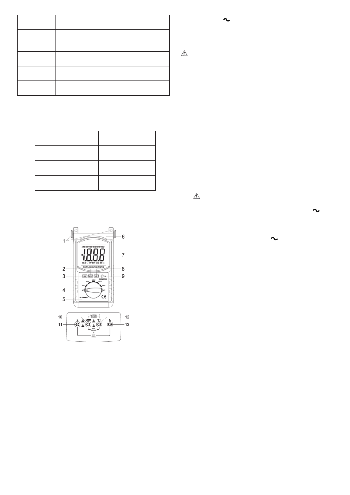
6. Parts
(1) Installaon hole
(2) Insulaon resistance test/stop buon (high voltage start buon):
TEST/STOP
(3) Data hold buon: HOLD
(4) Funcon selecon switch
(5) Meter case
(6) Shockproof protecve sleeve
(7) LCD display
(8) Display backlight buon: LIGHT
(9) High voltage indicator: HV
(10) AC voltage ”COM” input terminal/insulaon resistance
measurement shield terminal/negave terminal of baery
charger
(11) Insulaon resistance test “EARTH” input (connect to earth
terminal of test target)
(12) AC voltage “V ” input/posive terminal of baery charger
(13) Insulaon resistance test “LINE” input
7. Operaon Instrucons
(1) Safety Precauons
Beware! High Voltage!
a. Aer the insulaon resistance test is completed, make sure that
the high voltages in the test target has fully discharged.
b. Do not touch the test target during the measurement process
and beware of high voltage shocks.
c. When measuring insulaon resistance, do not allow the
addion of external voltages to the test circuit.
d. When measuring insulaon resistance, the test target should
not be “live” and should be safely grounded. Before tesng, the
two test terminals of the test target should be short circuited to
discharge any remaining electricity.
e. Before tesng, make sure the rotary switch is in the correct
posion, and the test wires are connected properly to the test
target.
f. Aer pressing the high voltage buon, high voltage of
100V-5000V (depending on sengs) will be output between the
“L” and “E” terminals. Do not touch the meter or the exposed
parts of the test target at this me, otherwise
there may be
risks of electric shock.
(2) AC Voltage Test
a. Do measure voltages over 750V.
b. Meter input terminal connecon
Insert the plug of the red test probe into the meter’s “V ”
terminal port, and insert the plug of the black test probe into
the meter’s “COM” terminal port.
c. Test target connecon
Turn the rotary switch to the “750 V ” posion, and ensure
reliable contact of the probes with the test target.
d. The screen will then display
a number that represents the AC
voltage between the two terminals of the test target.
(3) Insulaon Resistance Test
a. Meter input terminal connecon
Take the plug of the red test probe (or red high voltage test probe in
6688B/6688F/6688BR/6688FR), plug it into the meter’s “L” terminal
port, and insert the plug of the black probe (the one with the alligator
clip) into the meter’s “E” terminal port.
b. Test terminal connecon
The wire for the meter’s “E” terminal (black with the big test clip) is
the ground connecon;
The wire for the meter’s “L” terminal (red test probe, high voltage test
probe for 6688B/F/6688BR/6688FR) is the “line” connecon;
The wire for the meter’s “COM” terminal (black with test probe and a
small alligator clip) is the shielded cable for insulaon resistance
tesng. If necessary, the plug of the black test probe with the small
alligator clip can be inserted into the meter’s “COM” terminal port.
During measurement, the small alligator clip can be connected to the
test target’s ground terminal to eliminate measurement error caused
by leakage current from the product’s surface to ensure
measurement accuracy and read out value stability.
c. Selected rated test voltage
Turn the rotary switch to the corresponding output voltage level
(100V/250V/500V/1000V/2500V/2500V) to produce the specied
measurement voltage for the insulaon resistance test.
d. Tesng
Take the black test probe (with the alligator clip), and clip it to the
terminal of the test target and the red test probe (or high voltage test
probe). Connect the black test probe to the other terminal of the test
target. Ensure the test wires are connected properly with the test
object, then press the high voltage buon, “TEST/STOP”. When the
high voltage indicator “HV” turns on,
this means the test voltage is

being produced and output, and the meter display will show a
number that represents the insulaon resistance value.
e. Stop tesng
Aer tesng, press the high voltage buon, “TEST/STOP”, and the
“HV” indicator will disappear to indicate that the high voltage output
has stopped. Then turn the rotary switch to the “OFF” posion and let
the residual charge from the capacitave load in the test target
discharge rst to prevent injury from the residua
l charge. Then,
remove the test wires to complete the test.
(4) Data Hold
Press the data hold buon, “HOLD”, once under any sengs, and the
current detected measurement will remain on the screen. The “HOLD”
icon will appear. Press the “HOLD” buon one more me to cancel
the funcon.
(5) Display Backlight
Aer powering on, press the backlight buon, “LIGHT”, and the
display backlight will turn on. Aer approximately 10 seconds without
any ope
raons, the backlight will turn o automacally.
8. Baery Replacement (6688B, 6688C, 6688F)
Or Baery Charging (HP-6688BR, CR, FR)
Take note of the baery levels when using the meter. When the “ ”
symbol appears on the display, the baery level is low. You should
replace or recharge the baery in a mely manner. The steps to
replace baeries are as follows:
1. Turn the rotary switch to the “OFF” posion.
2. Take o the shockproof protecve
cover, remove the screws on
the baery cover, and open the baery cover to take out the old
baeries.
3. Replace with 6 new 1.5V AA baeries and make sure the
polaries are inserted correctly. Be aware that it is desirable to
change all 6 baeries at once instead of only replacing some of
them, since this may aect the usage life of the new baeries.
Although any standard 1.5V AA baery can be used, alkaline
baeries are preferr
ed for their extended baery life.
4. Close the baery cover and use the screws to fasten the cover.
Then, replace the shockproof cover.
5. Take the baeries out if the meter will not be used for an
extended period of me.
6. The 6688BR/6688CR/6688FR models use a 9.6V NiMH
rechargeable baery. When baery is low, use the charger to
recharge it in a mely manner. The steps for recharging are as
follows:
a. Turn the rotary switch to the “OFF
” posion.
b. Plug the black plug of the baery charger into the meter’s “COM”
port, and the red plug into the “V ” port. Make sure to plug
them in correctly.
c. Connect the baery charger into a 220V or 110V mains power
supply. The indicator lights on the charger will turn red and start
ashing to indicate that charging is in progress. Charging is
complete when the indicator lights turn green. When this
happens, the charger should be
disconnected in a mely manner
to stop the charging process.
d. Make sure not to turn the rotary switch while charging. The
switch can only be turned aer disconnecng from the charger.
9. Maintenance
Your meter is a precision electronic equipment and should be
properly maintained.
a. Do not use the meter when the back cover and the baery cover
are not closed properly.
b. Baeries can only be replaced aer removing the test p
robes
and when the power has been switched o. Open the baery
cover, then replace the baeries according to the relevant
specicaons and polaries.
c. The rechargeable baery should be charged in a mely manner
when running low on power to prevent the baery from
entering the “deep discharge” stage, which will aect its usage
life.
d. When the meter will not be used for an extended period of me,
the baery should be re
moved, and stored in a dry and
well-venated area.
e. Do not modify the internal circuitry of the meter at will.
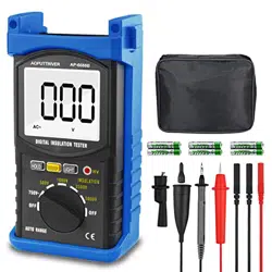
10. Accessories Descripon
Set of dedicated test wires x 1, User Manual x 1, 1.5V AA baeries x 6
(6688B/6688C/6688F), 9.6V NiMH rechargeable baery x
1(6688BR/6688CR/6688FR, already installed), baery charger x 1
(6688BR/6688CR/6688FR).
Images and descripons of the product given above are for
reference purposes only. There will be no further nocaon should
there be any discrepancies or updat
es. Please refer to the actual
product.
