Digital Anemometer
Operation Manual
10
Digital Anemometer
Operation Manual
4.12.2 W hen necessary, the meter can be used by hang.
4.13 Replacing battery
4.13.1 If the “ ” sign appears, this indicates that the battery should be
replaced.
4.13.2 Power off the meter and remove the battery cover.
4.13.3 Replace the old battery.
4.13.4 Install the battery cover pro pe rly.
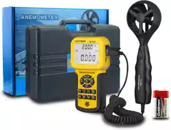
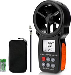
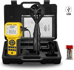
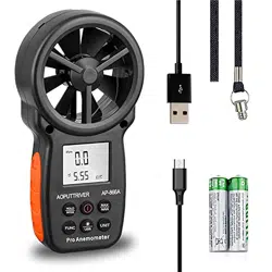
5. Attachments
(1) Battery 1.5V, AAA 2pcs
(2)
Detector
Bracket
1pc
(3)
Packaging
Bag
1pc
(4)
Operation
Manual
1pc
(5) CD 1pc

Table of Contents
1. Safety information
1.1 Preparation
1.2 Usage
1.3 Marking
1.4 Maintenance
2. Description
2.1 Part name
2.2 Button description
2.3 Sign definition
3. Specification
3.1 General
3.2 Technique data
4. Operating guidance
4.1 Power On/Off
4.2 Reading hold
4.3 Backlight function
4.4 Wind speed mea surement
4.5 Wind speed unit selection
4.6 Area setting
4.7 Air volume measurement
4.8 Air volume unit selection
4.9 Temperature unit selection
4.10 Temperature mode selection
4.11 USB real time da ta uploading
4.12
Use tr
ipod connection receptacle
4.13 Replace battery
5. Attachments
9
Digital Anemometer
Operation Manual
4.8 Air volume unit selection
When using the meter to measure air volume, you can press the
“
UNIT
” key to select the measurement unit your required (CMS, CMM,
CFM).
4.9 Temperature unit selection
Long press the “
UNIT”
key for 3 seconds to switch temperature un it
(°C, °F).
4.10 Temperature mode selection
Long press the “
HOLD/MODE
” key for 3 seconds to switch temperature
mode (ambient temperature, dew point temperature and wet bulb
temperature).
4.11 USB real time data uploading
Long press the “
/USB
” key for 3 seconds to enable or disable USB
real time data uploading function.
Detailed steps are shown as follows:
1ĕUse CD to install the PC software and the USB drivers.
2ĕPower on the meter and connect it to a computer with USB cable .
3ĕLaunch the PC software.
4ĕLong press the “
/USB
” key for 3 seconds to enable the USB function
of the meter.
5ĕThe PC s oftware displays data and diagrams.
6ĕSave or print data.
4.12 Using tripod connection receptacle
4.12.1 When necessary, the meter can be fixed on a tripod.

1
Digital Anemometer
Operation Manual
1. Safety Information
Please read carefully the following safety information before usage
and maintain this anem ometer while using it according to operating
guidance, otherwise, the anemometer may be damaged. The anemometer
will provide satisfactory services to you if you use and protect it
appropriately.
1.1 Preparation
1.1.1 Please check for damage during transportation after receiving the
anemometer.
1.1.2 If it should be stored and shipped under hard conditions, please
confirm that whether the meter is damaged.
1.2 Usage
1.2.1 The meter should be used in the range of spe cified ambient
temperature an d humidity.
1.2.2 If you notice any abnormality or failure, it should stop using.
1.2.3 Don’t store or use the meter under the conditions of direct sunlig ht,
high temperature and high humidity.
1.2.4 Don’t touch the fan blades with excessive force.
1.2.5 Don’t directly expose the blades in the hard light to avoid reading
error.
1.3 Marking
The mark indicates compliance with EMC requirements.
Important Safet y Information
1.4 Maintenance
1.4.1 Repair or maintenance should be implemented by trained personnel.
1.4.2 If there is dust on the fan blade, please blow it with clean ai r or scrub
gently with a damp cloth and mild detergent.
1.4.3 Clean the meter with a damp cloth and mild detergent. Don’t use
abrasive material or solvent.
1.4.4 The meter should be powered off when it is not in use.
1.4.5 The meter will consume small current, about 5ȝA, after shut do wn. If
the meter is not to be used for a long period, batteries should be
8
Digital Anemometer
Operation Manual
Place the detector (fan) into the test environmen t, "VEL" symbol will
display on the screen, measurement is done with the fan surface
perpendicularly to the wind direction.
Note:
1. If the detector (fan) is not aiming at the wind direction, which will bring
the measurement error.
2. For steady wind, the detector (fan) will get maximum reading when it is
aiming at the wind direction.
4.5 Wind speed measurement
When using the meter to measure air volume, you can press “UNIT”
key to select the measu rement unit you required (m/s, km/h, MPH, ft/m, ft/s,
knots).
4.6 Area setting
To measure air volume, you should first determine the area of air f lue
to be, area input steps are shown as following:
ķĕPress “FUN” key to make “AREA” display on the screen .
ĸĕ
Use the “MAX/MIN” and “UNIT” keys to adjust value and unit, after
adjusting area unit (m², ft²), then press “MAX/MIN” key. There
should be an audible buzz, indicating that area input is completed
and settings are saved.
ĹĕTo change the area setting, please repeat the step ĸ.
4.7 Air volume measurement
Place the detector (fan) into the test environment. Use the “FUN” key to set
the meter to the Air volume measurement mode; the "FLOW" symbol
should display on the screen.
Measurement is done with the fan surface perpendicula r to the wind
direction.
Note:
1. If the detector (fan) is not aligned in the wind direction, the
measurement can be skewed.
2. For steady wind, the detector (fan) will get maximum reading when it is
aiming at the wind direction.
2
Digital Anemometer
Operation Manual
removed to prevent damaging the meter.
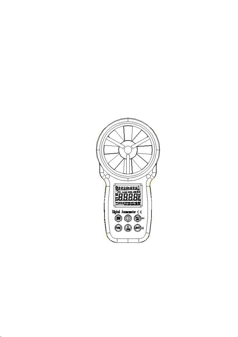
2. Description
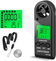
- This meter is a digital anemometer for measuring the ambient
temperature, humidity, dew point temperature, wet bulb tempe rature,
wind speed, and ai r volume.
- This meter is a portable, professional measuring instrument with
large-screen LCD and backlight, multi-unit switching functions.
- This meter can be used for hand-held or fixed measurement.
- This meter has the functions of reading hold, maximum , minimum, etc.
- It has a low battery indicator and USB real time data uploading functions.
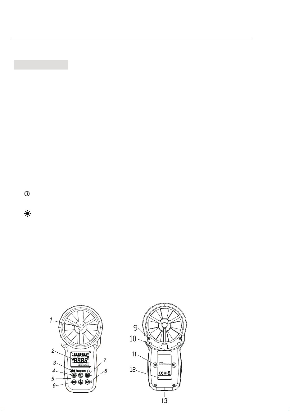
2.1 Part name
⑴ Fan
⑵ LCD
⑶“
”
→
Power switch
⑷
“HOLD/MODE”
holddisplay, switchtemperaturemode
⑸“
/USB
”
→
Backlight/USB real time data
⑹“
FUNC
”
→
Function switching button
⑺
Maximum/Minimum button
⑻“
UNIT
”
→
Unit switching button
⑼ Fan retaining bolt hole
⑽transducer ai r vent
⑾Battery housing cover retaining bolt hole
⑿ Battery cover
⒀ Connection hole for fixing measurement bracket
7
Digital Anemome ter
Operation Manual
3.2.9 Relative humidity
Measuring
range
Resolut
ion
Accuracy
(20~
80)%RH
0.1%R
H
3%RH@25°C
(<20
or >80)%RH
0.1%R
H
5%RH@25°C
4. Operating guidance
4.1 Power On/Off
Press the “ ” key more than 2 seconds to turn on , push it again to turn off the
anemom eter power.
4.2 Reading hold
In the measurement process, if the reading should be kept, press
"
HOLD
" key to lock the reading, and display the
HOLD
symbol; press it
again to unlock.
4.3 Backlight
In the measurement process, if the ambient light is too dark to read,
you can press " " key to open the backlight. Backlight timer is set to 15
seconds. During this period, you can press " " key again to turn off
backlight at any time.
Note:
The luminous body of backlight is LED with large operating current.
Frequently using backlight will shorten battery life. Do not use backlight
when unnecessary.
When the battery voltage ≤ 7V, the " " (low battery) symbol will show
on the display. However, in the case of using the backlight, if the battery
voltage ≥ 7V, the battery voltage dro ps because of its larger operating
current, "
" symb ol may show (when "
" symbol is showing, the
accuracy of the measurement can’t be guaranteed). At this moment, you
needn’t replace batte ry until the "
" s ymbol display again under
normal use condition without using ba cklight.
4.4 Wind speed measurement

3
Digital Anemome ter
Operation Manual
2.2 Button description
Button:
Switch for meter powering on/off.
/USB button
Switch for turning on/off the backlight and USB transmission.
HOLD/MODE button
Switch for reading retention and temperat ure mode.
FUN button
It is used for switching among the functions of wind speed measu rement,
area setting and air volume measurement. Long press for three seconds
to enable or disable "Auto Power-Off" function.
MAX/MIN button
Switch maximum/minimum/normal mode, long press to exit.
UNIT button
Switch unit, are a (m², ft²), long press to switch (°C, °F)
Wind speed (m/s, km/h, mil/h, ft/m, ft/s, knots),
Air volume (C MS, CMM, CFM).
2.3 Sign definition
Indicates Auto Power-Off status
H Reading hold state
VEL Wind speed measuremen t state
FLOW Air volume mea surement state
AREA Area setting required by air volume
DP Indicates that the current mode is dew point temperature mode
WB Indicates that the current mode is wet bulb temperature mode
°C, °F Temperature unit.
%RH Relative humidity sign
USB Indicates that USB real time data uploading is enabled
MAX Displays maximum after ente ring maximum /minimum mode
MIN Displays minimum after ente
ring maximum/minimum mode
6
Digital Anemometer
Operation Manual
3.2.5 MPH
Measuring
range
Resolut
ion
Accuracy
0.90 ~ 67.20
MPH
0.01MP
H
±(2.0% reading
+ 5 characters)
67.20~90.00
mil/h
For reference
only
3.2.6 ft/m
Measuring
range
Resolut
ion
Accuracy
78 ~ 5900
ft/m
1ft/m ±(2.0%
reading + 5
characters)
5900 ~ 7874
ft/m
For reference
only
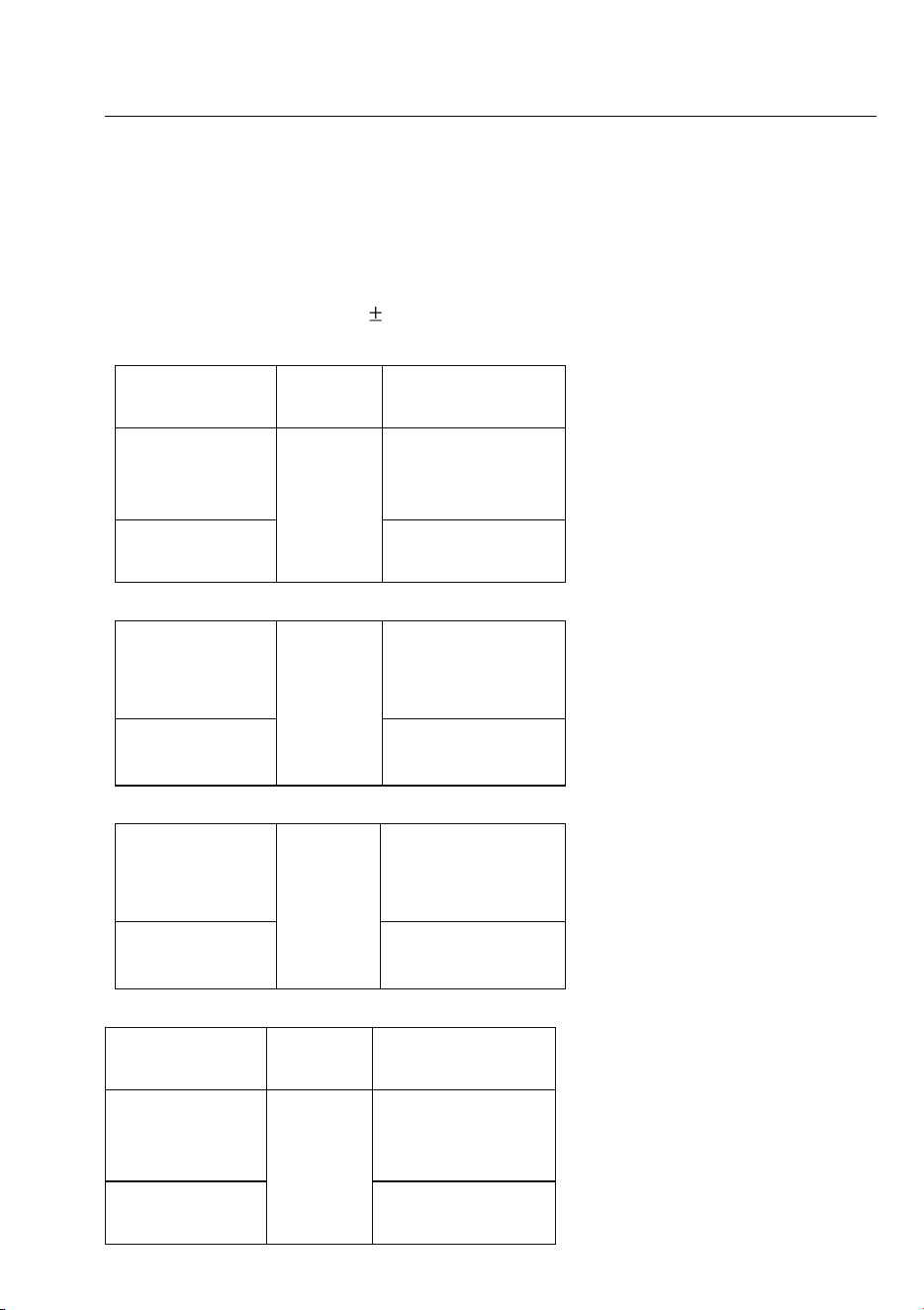
3.2.7 Air volume unit
CFM 0-
99990
(Area) 0 -
9.999 ft²
CMM 0-
99990
(Area) 0 -
9.999 m²
CMS 0 -
9999
(Area) 0 -
9.999 m²
3.2.8 Ambient tempera ture, dew point temperature, wet bulb temperature
Measuring
range
Resolut
ion
Accuracy
-10°Cl60°C 0.1°C
1.5°C
14°FlĒ
140°F
0.1°F
2.7°F
4
Digital Anemometer
Operation Manual
m² Indicates that the current area setting unit is square meter
ft² Indicates that the current area setting unit is square foot
CMM Cubic meters per minute
CMS Cubic meters pe r second
CFM Cubic feet per minute
knots Nautical miles per hour, 1850 meters per hour
ft/s Feet per second
ft/m Feet per minute
m/s Meters per second
Km/h Kilometers per hour
MPH Nautical miles per hour
Low battery indicator
3. Specification
The meter should be recalibrated under the condition of 18°C l 28°C,
relative humidity ģ75% every year.
3.1 General
3.1.1 Work height: Maximum 2000m
3.1.2 Work mode: Frequency of wind speed conversion
3.1.3 Display: LCD
3.1.4 Maximum show value: 9999
3.1.5 Samplin g time: About 0.4s/time.
3.1.6 Auto power off: Turn off after 10 minutes
3.1.7 Low battery indicator:
sign displays on LCD.
3.1.7 Work power: 2×1.5V AAA batteries.
3.1.8 Operation environment:
Relative humidityĺ 0~85%RH, no moisture condensation.
Temperatureĺ 0°C~40°C, no moisture condensation.
3.1.9 Detector (fan) operatio n environment:
Relative humidityĺ 0~95%RH, no moisture condensation.
Temperatureĺ -20°C~70°C, no moisture condensation.
3.1.10 Storage environment:
Relative humidityĺ 0~80%RH, no moisture condensation
5
Digital Anemome ter
Operation Manual
Temperat ureĺ -10°C~6 0°C, no moisture condensation
3.1.11 Dimension: Meter ĺ165LX85 WX38Hmm.
3.1.12 Weight: About 200g
3.2 Techni que data
Ambient temperature: 23 5°C, Relative humidity: <75%
3.2.1 m/s
Measuring
range
Resolut
ion
Accuracy
0.80 ~ 30.00
m/s
0.01
m/s
±(2.0% reading
+ 50
characters)
30.00 ~
40.00 m/s
For reference
only
3.2.2 km/h
1.40~108.00
km/h
0.01km
/h
±(2.0% reading
+ 50
characters)
108.0 ~ 144.0
km/h
For reference
only
3.2.3 ft/s
1.30 ~ 98.50
ft/s
0.01
ft/s
±(2.0% reading
+ 50
characters)
98.50 ~
131.20 ft/s
For reference
only
3.2.4 knots
Measuring
range
Resolut
ion
Accuracy
0.80 ~ 58.30
knots
0.01
knots
±(2.0%
reading + 50
characters)
58.30~77.70
knots
For reference
only
3
Digital Anemome ter
Operation Manual
2.2 Button description
Button:
Switch for meter powering on/off.
/USB button
Switch for turning on/off the backlight and USB transmission.
HOLD/MODE button
Switch for reading retention and temperat ure mode.
FUN button
It is used for switching among the functions of wind speed measu rement,
area setting and air volume measurement. Long press for three seconds
to enable or disable "Auto Power-Off" function.
MAX/MIN button
Switch maximum/minimum/normal mode, long press to exit.
UNIT button
Switch unit, are a (m², ft²), long press to switch (°C, °F)
Wind speed (m/s, km/h, mil/h, ft/m, ft/s, knots),
Air volume (C MS, CMM, CFM).
2.3 Sign definition
Indicates Auto Power-Off status
H Reading hold state
VEL Wind speed measuremen t state
FLOW Air volume mea surement state
AREA Area setting required by air volume
DP Indicates that the current mode is dew point temperature mode
WB Indicates that the current mode is wet bulb temperature mode
°C, °F Temperature unit.
%RH Relative humidity sign
USB Indicates that USB real time data uploading is enabled
MAX Displays maximum after ente ring maximum /minimum mode
MIN Displays minimum after ente
ring maximum/minimum mode
6
Digital Anemometer
Operation Manual
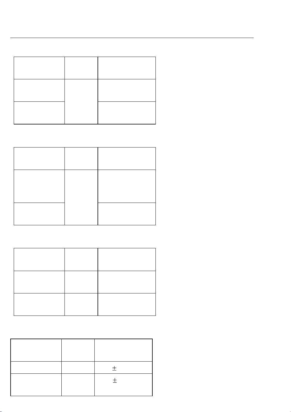
3.2.5 MPH
Measuring
range
Resolut
ion
Accuracy
0.90 ~ 67.20
MPH
0.01MP
H
±(2.0% reading
+ 5 characters)
67.20~90.00
mil/h
For reference
only
3.2.6 ft/m
Measuring
range
Resolut
ion
Accuracy
78 ~ 5900
ft/m
1ft/m ±(2.0%
reading + 5
characters)
5900 ~ 7874
ft/m
For reference
only
3.2.7 Air volume unit
CFM 0-
99990
(Area) 0 -
9.999 ft²
CMM 0-
99990
(Area) 0 -
9.999 m²
CMS 0 -
9999
(Area) 0 -
9.999 m²
3.2.8 Am bient temperature, dew point temperature, wet bulb temperature
Measuring
range
Resolut
ion
Accuracy
-10°Cl60°C 0.1°C
1.5°C
14°FlĒ
140°F
0.1°F
2.7°F
2
Digital Anemometer
Operation Manual
removed to prevent damaging the meter.
2. Description
- This meter is a digital anemometer for measuring the ambient
temperature, humidity, dew point temperature, wet bulb tempe rature,
wind speed, and ai r volume.
- This meter is a portable, professional measuring instrument with
large-screen LCD and backlight, multi-unit switching functions.
- T his meter can be used for ha nd -held or fixed measurement.
- T his meter has the function s of reading hold, maximum, minimum, etc.
- It has a low battery indicator and USB real time data uploading functions.
2.1 Part name
⑴ Fan
⑵ LCD
⑶“
”
→
Power switch
⑷
“HOLD/MODE”
holddisplay, switchtemperaturemode
⑸“
/USB
”
→
Backlight/USB real time data
⑹“
FUNC
”
→
Function switching button
⑺
Maximum/Minimum button
⑻“
UNIT
”
→
Unit switching button
⑼ Fan retaining bolt hole
⑽transducer ai r vent
⑾Battery housing cover retaining bolt hole
⑿ Battery cover
⒀ Connection hole for fixing measurement bracket
7
Digital Anemome ter
Operation Manual
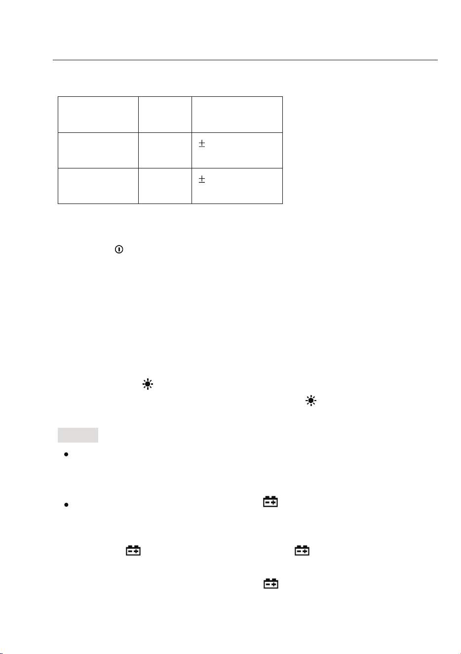
3.2.9 Relative humidity
Measuring
range
Resolut
ion
Accuracy
(20~
80)%RH
0.1%R
H
3%RH@25°C
(<20
or >80)%RH
0.1%R
H
5%RH@25°C
4. Operating guidance
4.1 Power On/Off
Press the “ ” key more than 2 seconds to turn on , push it again to turn off the
anemom eter power.
4.2 Reading hold
In the measurement process, if the reading should be kept, press
"
HOLD
" key to lock the reading, and display the
HOLD
symbol; press it
again to unlock.
4.3 Backlight
In the measurement process, if the ambient light is too dark to read,
you can press " " key to open the backlight. Backlight timer is set to 15
seconds. During this period, you can press " " key again to turn off
backlight at any time.
Note:
The luminous body of backlight is LED with large operating current.
Frequently using backlight will shorten battery life. Do not use backlight
when unnecessary.
When the battery voltage ≤ 7V, the " " (low battery) symbol will show
on the display. However, in the case of using the backlight, if the battery
voltage ≥ 7V, the battery voltage dro ps because of its larger operating
current, "
" symb ol may show (when "
" symbol is showing, the
accuracy of the measurement can’t be guaranteed). At this moment, you
needn’t replace batte ry until the "
" s ymbol display again under
normal use condition without using ba cklight.
4.4 Wind speed measurement

1
Digital Anemome ter
Operation Manual
1. Safety Information
Please read carefully the following safety information before usage
and maintain this anem ometer while using it according to operating
guidance, otherwise, the anemometer may be damaged. The anemometer
will provide satisfactory services to you if you use and protect it
appropriately.
1.1 Preparation
1.1.1 Please check for damage during transportation after receiving the
anemometer.
1.1.2 If it should be stored and shipped under hard conditions, please
confirm that whether the meter is damaged.
1.2 Usage
1.2.1 The meter should be used in the range of spe cified ambient
temperature an d humidity.
1.2.2 If you notice any abnormality or failure, it should stop using.
1.2.3 Don’t store or use the meter under the conditions of direct sunlig ht,
high temperature and high humidity.
1.2.4 Don’t touch the fan blades with excessive force.
1.2.5 Don’t directly expose the blades in the hard light to avoid reading
error.
1.3 Marking
The mark indicates compliance with EMC requirements.
Important Safet y Information
1.4 Maintenance
1.4.1 Repair or maintenance should be implemented by trained personnel.
1.4.2 If there is dust on the fan blade, please blow it with clean ai r or scrub
gently with a damp cloth and mild detergent.
1.4.3 Clean the meter with a damp cloth and mild detergent. Don’t use
abrasive material or solvent.
1.4.4 The meter should be powered off when it is not in use.
1.4.5 The meter will con sume small current, about 5ȝA, after shutdown. If
the meter is not to be used for a long period, batteries should be
8
Digital Anemometer
Operation Manual
Place the detector (fan) into the test environmen t, "VEL" symbol will
display on the screen, measurement is done with the fan s urface
perpendicularly to the wind direction.
Note:
1. If the detector (fan) is not aiming at the wind direction, which will bring
the measurement error.
2. For steady wind, the detector (fan) will get maximum reading when it is
aiming at the wind direction.
4.5 Wind speed measurement
When using the meter to measure air volume, you can press “UNIT”
key to select the measu rement unit you required (m/s, km/h, MPH, ft/m, ft/s,
knots).
4.6 Area setting
To measure air volume, you should first determine the area of air f lue
to be, area input steps are shown as following:
ķĕPress “FUN” key to make “AREA” display on the screen .
ĸĕ
Use the “MAX/MIN” and “UNIT” keys to adjust value and unit, after
adjusting area unit (m², ft²), then press “MAX/MIN” key. There
should be an audible buzz, indicating that area input is completed
and settings are saved.
ĹĕTo change the area setting, please repeat the step ĸ.
4.7 Air volume measurement
Place the detector (fan) into the test environment. Use the “FUN” key to set
the meter to the Air volume measurement mode; the "FLOW" symbol
should display on the screen.
Measurement is done with the fan surface perpendicula r to the wind
direction.
Note:
1. If the detector (fan) is not aligned in the wind direction, the
measurement can be skewed.
2. For steady wind, the detector (fan) will get maximum reading when it is
aiming at the wind direction.
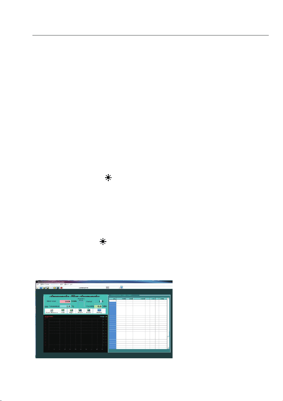
Table of Contents
1. Safety information
1.1 Preparation
1.2 Usage
1.3 Marking
1.4 Maintenance
2. Description
2.1 Part name
2.2 Button description
2.3 Sign definition
3. Specification
3.1 General
3.2 Technique data
4. Operating guidance
4.1 Power On/Off
4.2 Reading hold
4.3 Backlight function
4.4 Wind speed mea surement
4.5 Wind speed unit selection
4.6 Area setting
4.7 Air volume measurement
4.8 Air volume unit selection
4.9 Temperature unit selection
4.10 Temperature mode selection
4.11 USB real time da ta uploading
4.12
Use tr
ipod connection receptacle
4.13 Replace battery
5. Attachments
9
Digital Anemome ter
Operation Manual
4.8 Air volume unit selection
When using the meter to measure air volume, you can press the
“
UNIT
” key to select the measurement unit your required (CMS, CMM,
CFM).
4.9 Temperature unit selection
Long press the “
UNIT”
key for 3 seconds to switch temperature un it
(°C, °F).
4.10 Temperature mode selection
Long pres s the “
HOLD/MODE
” key for 3 seconds to switch temperature
mode (ambient temperature, dew point temperature and wet bulb
temperature).
4.11 USB real time data uploading
Long press the “
/USB
” key for 3 seconds to enable or disable USB
real time data uploading function.
Detailed steps are shown as follows:
1ĕUse CD to install the PC software and the USB drivers.
2ĕPower on the meter and connect it to a computer with USB cable .
3ĕLaunch the PC software.
4ĕLong press the “
/USB
” key for 3 seconds to enable the USB function
of the meter.
5ĕThe PC s oftware displays data and diagrams.
6ĕSave or print data.
4.12 Using tripod connection receptacle
4.12.1 When necessary, the meter can be fixed on a tripod.

Digital Anemometer
Operation Manual
10
Digital Anemometer
Operation Manual
4.12.2 W hen necessary, the meter can be used by hang.
4.13 Replacing battery
4.13.1 If the “ ” s ign ap pears, this indicates that the battery should be
replaced.
4.13.2 Power off the meter and remove the battery cover.
4.13.3 Replace the old battery.
4.13.4 Install the battery cover pro pe rly.
5. Attachments
(1) Battery 1.5V, AAA 2pcs
(2)
Detector
Bracket
1pc
(3)
Packaging
Bag
1pc
(4)
Operation
Manual
1pc
(5) CD 1pc