- 1 -
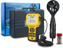
AIR FLOW ANEMOMETER
INSTRUCTION MANUAL
Thank you for purchasing our company Air Flow Anemometer.
This manual provides relative information on how to use the Air
Anemometer and warning in operation Please make some simple test
measurement to ensure proper performance of the unit.
To make the best use of this Anemometer, read this Manual thoroughly
before use it. Please Keep this Manual Handy for reference.
1. Before Use Notice
Check up
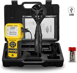
Carefully unpack your kit and ensure that you have the following Items. In
case that any items is missing or if you find any mismatch or
damage .promptly contact your local dealer.
Air Flow Anemometer unit----------------------- 1pcs
Wind velocity sensors ------------------------ 1pcs
Software Disc For Anemometer ------------------ 1pcs
USB Computer connecting cable------------------1pcs
6F22 or NEDA 1604 9V battery -------------------1pcs
English/Chinese Instruction Manual ----------------1pcs
Warranty Card ------------------------------ 1pcs
PP Packing box ----------------------------- 1pcs
Features
Measurement of wind velocity, temperature and flow
Unit conversion of wind velocity, temperature and flow
Measurement of maximum and minimum wind velocity
Measurement of 2/3 V max and average wind flow
Data holding, storing and deleting function
Low battery indicating function
Auto power off function (Power off automatically if no any operation for
5 Minutes)
Memory of 600 records
Backlight function
Connecting to PC by USB cable
Pressing key audio alert
Large LCD display
Wind Handle Can Elongate
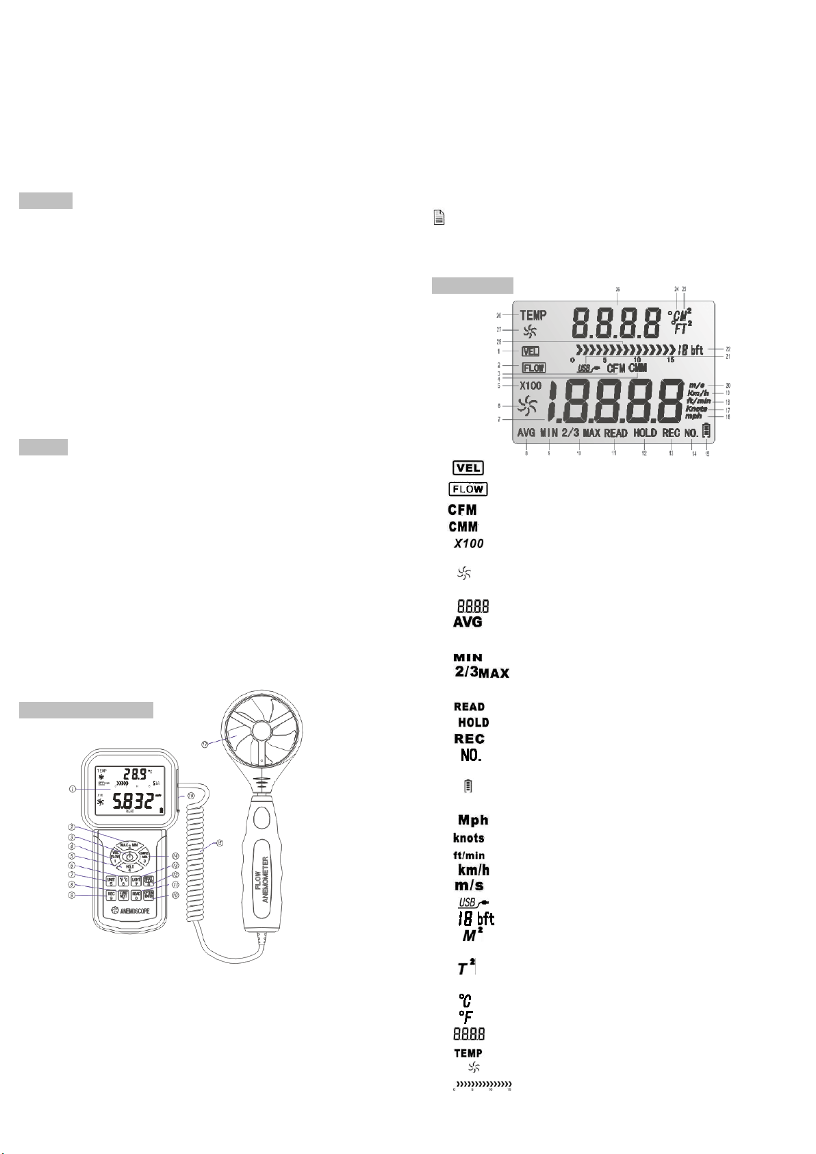
DIAGRAM OF THE UNIT
1). LCD display
2). Max/Min value switch
3). Power key: press once to power on, again for two seconds to power off
4). Wind velocity/flow transform key
5). Data holding key
6). Temperature unit switch
7) Unit transform key
8) Measuring key for average value of wind flow.
9) Data record key.
10) Wind flow AVG 2/3 MAX and figure input
11) Read out recorded data key
12) Reset key in "READ" mode/clear recorded
13) Backlight on/off key, press down to start the backlight function, again to
cancel.
14) Duct area input and sampling time setting key
15) Connecting wire
16) USB interface: insert one end of the connecting cable to this interface,
another to the available USB port of the computer.
17) Wind velocity sensors
NOTE:
Aforesaid key function descriptions are simple introduction.
Pleas read operation instructions parts for details.
LCD Display
1) :When measuring wind velocity, this symbol will appears
2) :When measuring wind flow, this symbol appears
3) :Wind flow unit (cube foot/minute)
4) :Wind flow unit (cube meter/minute)
5) :If measured value is over 9999, the symbol “X10 “ or “X100”
will appear.
6) :Big fans : indicate wind velocity /flow status, which was subject
to Wind Velocity and revolving.
7) :Wind velocity and flow display area.
8) : When measuring average values (one of the wind flow
measuring Method) this symbol appears.
9) : Showing minimum values.
10) :MAX2/3 of maximum value measurement (one of the
wind flow measuring method)
11) :This symbol will appear. While Read stored record data.
12) : Data holding
13) :Recording the using number and signals
14) :This symbol and serial number of stored record data will
appear. While Read stored record data.
15) :Low battery indicating symbol, please replace battery if
this symbol empty.
16) :Wind velocity unit (mile/hour)
17) :Wind velocity unit (sea mile/hour)
18) :Wind velocity unit (foot /minute)
19) :Wind velocity unit (kilometer/hour)
20) :Wind velocity unit (mete r/second)
21) :When connecting PC with USB cable, this symbol appears
22) :Beaufort scale
23) :M
2
is used to indicate duct area in square meter when
in flow function
:"T
2
" Is used to indicate duct area in square feet when
in flow function
24) :Wind temperature Celsius unit
:Wind temperature Fahrenheit unit
25) :Temperature value display or Duct area display area
26) :Wind temperature signal.
27) :small fan signal: indicate the Wind Temperature status
28) :Bar graph display of Beaufort scale

- 2 -
SPECIFICATIONS
1. Wind Velocity Range:
Unit
Wind Velocity
Resolution
Lowest
Point of
start value
Accuracy
m/s
0.0-45.0
0.001
0.3
±3%+0.1rdg
Ft/min
0.0-8800
0.01/0.1/1
60
±3%+20rdg
Knots
0.0-88.0
0.001/0.01
0.6
±3%+0.2rdg
Km/h
0.0-140.0
0.001
1.0
±3%+0.4rdg
Mph
0.0-100
0.001/0.01
0.7
±3%+0.2rdg
2. Wind flow range:
CMM: 0-999900m
3
/min
CFM: 0-999900 ft
3
/min
Unit
Range
Resolution
Area
CMM(M
3
/MIN)
0-999900
0.001-100
0.001-9999
CFM(FT
3
/MIN)
0-999900
0.001-100
0.001-9999
3. Unit Conversation:
m/s
Ft/min
Knots
Km/h
Mph
m/s
1
196.87
1.944
3.60
2.24
Ft/min
0.00508
1
0.00987
0.01829
0.01138
Knots
0.5144
101.27
1
1.8519
1.1523
Km/h
0.2778
54.69
0.54
1
0.6222
Mph
0.4464
87.89
0.8679
1.6071
1
4. Air Temperature Range:
Unit
Scale
Resolution
Accuracy
℃
0.0-45.0
0.1
±1.0℃
℉
32.0-113.0
0.1
±1.8℉
5 . Operation Conditions:
Temperature
Humidity
Host
0-50℃(32-122℉)
≤80%RH
Wind velocity sensors
0-60℃(32-140℉)
6. Storage Conditions:
Temperature
-10-60℃(14-140℉)
Humidity
≤80%RH
7. Power supply : 6F22 9V×1
8. Low battery indicating : 6.8V±0.2V
9. Stand by current ≤2μA
10. Operating Current Approx.18mA
11. Battery use life :20H (Continuous Use )
12. Dimensions:
Meter:163×85×34.5 ㎜
Vane: 251×72×30 ㎜
13. Net Weight :320.5g (Not Included Battery )
2. Operation
Measurement of Wind Velocity and Temperature
Recover the battery door , and install the batteries properly as shown in
figure 1.
Press the “ ” key, all the symbols will be shown on the screen for 1
second, then the unit goes into current wind velocity and temperature
measuring mode, the LCD screen shows as following figure2:
Figure 2
Select your desired wind velocity and temperature unit
(1) Press the “UNIT” key, the wind velocity unit will be auto change
from (m/s、km/h、ft/min、knots、mph), (default unit is m/s)
(2) Press the “℃/℉” , The temperature will be change between ℃/
℉ mode, defaulted as ℃.
Hold the Anemometer with your hand, place the vane in the air flow with
the air direction matching the direction of the arrows printed on the
inner walls of the vane (Pleas do not extruded the wind velocity sensors
leaf. Otherwise will cause the inaccuracy measurement)
Figure3
(1) Wait for two Sec, to make the data stability
(2) Place the vane in the same direction of the wind to capture the
accurate data.
(3) Press “LIGHT” Key to start the Backlight Function, Signal will be
display on the LCD press7 sec the led will lighten while the Vane
is revolving ,then press "LIGHT" BUTTON the LED will cut
off ,signal will disappear and the light function will turn off.
Wind /Air Temperature Measurement
(1) Wind temperature will test out when testing Wind Velocity, Small
Vanes pattern will showing along with the display of "TEMP"
Symbol.
(2) Press button ℃/℉ to Switch ℃/℉ or (number 6 key).
Note:
a If current is in wind flow measuring mode (on the left top of the
LCD will show "FLOW", you can turn it into wind velocity
measuring mode by pressing the "VEL/FLOW' key, vice versa.
b The defaulted model is last time you has setting
Measurement of Wind flow
Press the “VEL/FLOW” key to get into “FLOW” mode at this time the
LCD screen as shown in figure 4 :
Figure 4
(if the area value has been set before the last setting will be shown)
Select your desired unit of wind flow and duct area:
a Press the “UNIT” key, the wind flow unit will convert between
CMM and CFM
b Press the “UNIT” key, the area unit will convert between “M
2
” and
“FT
2
”.
c Area unit: "M
2
" and "FT
2
" will convert according with the
conversion of the wind flow unit.
If wind flow unit is CMM, the area unit will be “M
2
”;
If wind flow unit is CFM. the area unit will be “FT
2
”.
Press the “AREA” key, the numbers in the middle of the LCD will be
disappeared at this time press numeric keys to enter a new duct area,
such as1.2, then press the “ENTER” key to confirm. At this time the
LCD screen as shown in figure 5:
Figure 5
Place the vane in the duct area, take measurement of current wind flow
value right away. As shown in figure 6 :
Figure 6

- 3 -
Wind Flow Calculate Formula: Flow =velocity *(Free Area)
Testing Wind velocity : The Bar graphic (showing on the middle of
LCD )was subject to the increasing wind Flow/ Velocity
Note:
a without enter the duct area will lead to failing in taking
measurement of the wind flow.
If wind flow is larger than 9999, the LCD screen will show x10 or x100, and the
measured value is also x10 or x100.
Measurement of 2/3 V max Wind Flow
Press the “VEL/FLOW” key to entre "FLOW" mode, the LCD screen
shows in figure 7:
Figure 7
Select your desired unit by pressing the “UNIT” key, for example: select
CMM for wind flow unit, “M
2
” for area unit ,at this time the LCD screen
shows as above diagram.
Press the "AREA " key, Letter on the LCD will disappeared at this time
you can input duct area, such as 1.2, press “ENTER” key confirm press
again the “OPTION” key to select “2/3 V max”, here the LCD screen as
shown in figure 8
Figure 8
Aim the vane of the attached unit at duct area properly, take
measurement of 2/3 V max wind flow right away, press again the
“OPTION” key exit to measurement of 2/3 V max wind flow.
2/3 Max Wind flow calculate formula: FLOW =2/3×Max wind Velocity
×duct Area.
MEASUREMENT OF AVERAGE WIND FLOW
Press the “VEL/FLOW” key to get into “FLOW” mode, the LCD screen
shows as in figure 9:
Figure 9
Select your desired unit by pressing the “UNIT” key, for example: select
CMM for wind flow unit, “M2” for area unit, at this time the LCD screen
shows as above diagram
Press the “AREA” key, you can input duct area. such as 1.2, press the
“OPTION” key to select “AVERAGE”, the LCD shows as in figure10:
Figure10
Aim the vane at certain point of duct area properly, press the “NEXT” key,
on the right bottom of the LCD will show serial number, in the meantime
you can take measurement of the first group wind flow values. As shown
in figure 11:
Figure 11
Then select another test point, press the “NEXT” key to take
measurement of the second group average wind flow values. Repeat
above steps to measure as many as 12 groups average wind flow
values. As shown in figure 12:
Figure 12
Once again press the "OPTION key exit to measurement of average
wind flow.
Average Wind flow calculate formula
Flow =l/N ∑(Velocity)×(free Area)
Note
The average value only displays by pressing NEXT key , If there is
wind in the duct area, then the LCD Screen will shows the measured
Average Wind flow.
Max and min measurement .
In wind flow and velocity measuring process, press the “MAX/MIN” key
to obtain the maximum and minimum values, press again to exit. For
example:
(1) When measuring maximum value of wind velocity, a “MAX” will
be shown on the upper LCD screen, as shown in figure 13
Figure 13
(2) When measuring minimum value of wind velocity, a “MIN” will be
shown on the upper LCD screen, as shown in figure 14:
Note: Figure 14
Operation of Max/Min wind flow measurement is the same as wind velocity.
Date holding /Storage/Reading and clearing
Data holding:
on Measurement state, press the "HOLD" key to freeze the Data , press
the "HOLD' key again return to normal operation.
Data storage:
(1) instantaneous (one-shot) data storage: on Measurement state,
set the sampling rate=0 by pressing “SAMPLE” key and in put a
"0" sampling time and then press "ENTER". Now, each time
"REC" is pressed, the present reading will be stored.
(2) Automatic data storage: on Measurement state, press the
“SAMPLE” key and input sampling rate, (the sampling rate from
1-99 seconds using the numeric keys to enter your desire rate,)
then press the “ENTER” key to confirm. Press the “REC” key to
begin storing readings in every sampling rate. The “REC” icon will
appear on the LCD indicated the data storage function is
activated. Press again the “REC” key to finish data storage.
(Press “REC” Key stop recording.)
(3) hold the "CLR "button two seconds, and the screen shows
"CLR", all the records will be cleared
Reading data stored sequentially:
(1) Press the “READ” key, you can read the stored data in memory
sequentially, the LCD will first shows serial number then shows the
data. Short Press “RESET” key to return normal operation. In data
read, read to 10 if you need testing, once again return to read the
state, the data will be then 10 to read ( This product can store 600
set of data. When the storage area full, the "full" appeared, Press
the "RESET" button back to measurement state )As shown in
figure 15:
(2) read the value random
In "READ" state, press the "SAMPLE" button to enter the data read
serial number .Then press "ENTER" confirmed that can show,
press the "RESET" button to exit
stored store Figure 15

- 4 -
CONNECTION WITH PC
1. Requirement of computer configuration :
CPU : Pentium 600MHZ Or above ;
One free available USB Connecting Interface;
The lowest screen resolution of monitor is 800*600 (or
much higher ),color mode;
At least 8MB available memory;
At least 50MB available disk memory;
Operation system: MICROSOFTWINDOWS 98/ME/2000/XP HOME/XP
PROFESSIONAL 32BIT.With VBA project digital certificates
2. Install the software from the disc:
Place the attached Disc in your disc driver open the disc driver plate
symbol , double click the “setup .exe” program logo , Enter Program
installation window, click “NEXT” Enter next interface ,as show in
figure16
figure16
Please examination and accept or not to accept this agreement on.
click “NEXT” Enter next interface, as show in figure17
figure17
Input user information, click “NEXT” Enter next interface, as show in
figure18
Figure18
Choose the target directory ,then press “next” as show in figure19
Figure19
Choose whether to create a shortcut, as show in figure20
Figure20
This program will confirm whether installed to computer, then press
“Install”, as show in figure21
Figure21
Click “Finish” to complete the software installation, and the program
will be automatically generated on the tabletop of the PC. as show in
figure22
Figure22
3. Software Introduction
Double click the software quick way on the tabletop ( start by menu, the
route is Start / H856A / 856PC) ,as show in figure23
Figure23
Note:
A. If you want to delete this software, pleas open “Controlling Panel” then
double check “add/delete program” choose “HG856Arealtime” on
the list then click the “delete” button. According to the prompt of the
system operation.
B. You can check if Anemometer is connected well with the computer on
the state column:
The Anemometer icon is dynamic: Connection in good state
The Anemometer icon is still: Failed in connection
Menu Introduction
Order
Order function
Real Time Measure
Real time data measurement, the measured data
will real time be shown on the computer.
Open
Open measurement data file that is saved as the
LAB format
Save
Save real time measurement data
Exit
Quit the program
Tool bar introduction as shown in following figure:
Button
Function
Real time data measurement, the measured data will real time be
shown on the computer.
Import data stored in the anemometer to computer
Open measurement data file that is saved as the LAB format
Save real time measurement data
data displayed again.
Help
System information
Close the software

- 5 -
4. Insert one end of the connecting cable into the USB interface of the
top anemometer host, as shown in figure 24
Figure24
5.Insert other end of the connecting cable into free interface port of on
the computer back, as shown in figure 25
Figure 25
6. Online real time Measurement:
Click “Real Time Measure operation” in “File” menu or Real Time
Measure button, enter real time measuring mode. as show in figure.26
Figure 26
Button introduction:
Button
Function
Click to start real time measurement
Click it the data displayed again.
Click it the Wind Velocity and Temperature display range
getting smaller.
Click it the Wind Velocity and Temperature display range
getting bigger.
Click it the Wind Velocity and Temperature move left
side.
Click it the Wind Velocity and Temperature move right
side.
Note: the computer and the machine for real-time online measurement may
not directly disconnected, must secure delete again after pulling USB
interface.
Familiar trouble shooting
The following is a list of actions to be to ken if the unit is not working properly:
(1) Screen is blank
Check the battery is inserted correctly. Open the battery door
on the bottom rear of the unit. The “+” “-” symbols on the
battery should match the corresponding “+” “-” symbols on
the inside of the battery compartment.
(2) If the unit can not connect to PC normally, please check
the USB cable is OK, if the cable can not be used formally,
please replace for a new one.
(3) lf the unit can not read the wind flow value properly, please
check if the vane is block or not.
(4) If the unit can not read the wind temperature value properly,
please check if the heat resistor is fall off or damaged by
manual.
(5) If the unit can not read data properly, please check it is
operated under the rule temperature and humidity situation.
Note:
When not connecting to PC, the unit will power off automatically after
10 minutes if no any operation after power on.
Maintenance & Warranty
1). Maintenance
Replacing the battery and product maintenance:
a Remove the battery from the unit if it is not required for extended
periods of time in order to avoid damage to the battery
compartment and the electrode resulting from a leaking battery.
b After power on, if a symbol " " appears on the LCD, indicates
that you should replace the battery in order to avoid inaccurate
measuring reading. Otherwise the battery is very possible leak
that will seriously damage the unit life. The battery compartment
is on the down rear of the unit, open the battery door, re place
the old battery for a new 9V one (notice the battery polarity),
close the battery door with a screw knife to lock up.
Cleaning the casing:
Never use alcohol or thinner to clean the unit casing that will especially
erode the LCD surface; just clean the unit lightly as needed with little
clean water. Never impact the unit or used on humidity condition.
Do not store or use the unit in following locations where the unit may be
subject to:
a. Splashes of water or high levels of dust.
b. Air with high salt or sulphur content.
c. Air with other gases or chemical materials.
d. High temperature or humidity (above50℃, 90%) or direct sunlight.
2). Warranty:
About relative warranties please read provided warranty card.
We disclaims any liability due to: transportation damages; incorrect use
or operation; manipulation, alterations or repair attempts; without
warranty card, invoice.
Specific Declarations:
a The prod u ct design and the manual updating, repairing by
technician authorized by us, do not try any alternations or repair
attempts.
b Dispose of battery should in accordance with local laws and
regulations.
c If in data communication, the interrupt connection, cause the
user data loss or system to restart and therefore cause other
problems, has nothing to do with our company.
Above picture and content just for your reference. Please be subject to the
actual products if anything different or updated. Please pardon for not
informing in advance.