
OPERATION MANUAL
LCD MONITOR
MODEL:
PN-HE751
PN-HE651
PN-HC861
PN-HC751
PN-HC651

Table of Contents
Important Information �����������������������������������������������������������2 Recommended Use & Maintenance ������������������������������������8
Chapter 1 Installation
Setup Overview ������������������������������������������������������������������10
Mounting (for Customer) ����������������������������������������������������13
Mounting Precautions (For SHARP dealers and service
engineers)
����������������������������������������������������������������������������14
Mounting Location �������������������������������������������������������������� 15
Orientation ��������������������������������������������������������������������������16
Ventilation Requirements ����������������������������������������������������17
Mounting on Walls or Ceilings �������������������������������������������� 18
Chapter 2 Parts Names and Functions
Control Panel ����������������������������������������������������������������������21
Terminal Panel �������������������������������������������������������������������� 22
Wireless Remote Control ����������������������������������������������������23
Chapter 3 Connections
Wiring Diagram �������������������������������������������������������������������25
Connecting to a Personal Computer ����������������������������������26
Connecting to a Media Device with HDMI �������������������������27
HDMI-CEC Command ��������������������������������������������������������29
Internal Video Sources �������������������������������������������������������30
Media Player �����������������������������������������������������������������������30
Connecting a USB Device ��������������������������������������������������31
Chapter 4 Basic Operation
Power On and Off Modes ��������������������������������������������������� 33
Power indicator status ��������������������������������������������������������33
Energy Mode ����������������������������������������������������������������������33
When [RS-232C] is selected for control �����������������������������33
When [LAN] is selected for control ������������������������������������34
Operating Range for the Remote Control ���������������������������35
Showing the Information OSD ��������������������������������������������36
Switching Between Picture Modes ������������������������������������� 36
Setting the Aspect Ratio ����������������������������������������������������� 37
OSD (On-Screen Display) Controls ������������������������������������ 38
Using the Media Player Menu ��������������������������������������������40
Chapter 5 Advanced Operation
Creating a Power Schedule ������������������������������������������������44
Using Picture Modes ����������������������������������������������������������45
Setting Security and Locking the Monitor Controls ������������46
Locking the Button Controls �����������������������������������������������47

Chapter 6 External Control
Controlling the Monitor via RS-232C ����������������������������������50
Controlling the Monitor via LAN ������������������������������������������51
HTTP Browser ���������������������������������������������������������������������53
Commands �������������������������������������������������������������������������55
Chapter 7 Troubleshooting
When a problem occurs with the monitor ���������������������������58
Nothing is displayed �����������������������������������������������������������58
The image is not displayed correctly ���������������������������������59
An instruction or caution screen is displayed ��������������������60
Others (when connected to a computer) ���������������������������60
Others (remote control, speakers) �������������������������������������60
Others (when connected via RS-232C or LAN) �����������������61
When using a media player ������������������������������������������������61
When using a video device ������������������������������������������������61
Chapter 8 Specications
Compatible Signal List �������������������������������������������������������63
PN-HE751 ��������������������������������������������������������������������������� 65
PN-HE651 ��������������������������������������������������������������������������� 66
PN-HC861 ��������������������������������������������������������������������������67
PN-HC751 ��������������������������������������������������������������������������68
PN-HC651 ��������������������������������������������������������������������������69
Appendix A Trademark and Software License
Appendix B OSD Controls List
Video Settings ��������������������������������������������������������������������72
Audio Settings ��������������������������������������������������������������������74
Setup ����������������������������������������������������������������������������������75
Control Settings ������������������������������������������������������������������77
Media Player �����������������������������������������������������������������������78
Schedule ����������������������������������������������������������������������������79
Appendix C Others
RS-232C command table ���������������������������������������������������82
Intellectual Property Rights and Other Matters ������������������84

1
IMPORTANT:
To aid reporting in case of loss or theft, please record the
product’s model and serial numbers in the space provided.
The numbers are located in the rear of the product.
Model No.:
Serial No.:
U.S.A. ONLY
2
IMPORTANT INFORMATION
WARNING: TO REDUCE THE RISK OF FIRE OR ELECTRIC SHOCK, DO NOT EXPOSE THIS PRODUCT
TO RAIN OR MOISTURE.
CAUTION: TO REDUCE THE RISK OF ELECTRIC
SHOCK, DO NOT REMOVE COVER.
NO USER-SERVICEABLE PARTS
INSIDE.
REFER SERVICING TO QUALIFIED
SERVICE PERSONNEL.
The lightning ash with arrowhead symbol, within
a triangle, is intended to alert the user to the
presence of uninsulated “dangerous voltage”
within the product’s enclosure that may be of
sufcient magnitude to constitute a risk of electric
shock to persons.
The exclamation point within a triangle is
intended to alert the user to the presence of
important operating and maintenance (servicing)
instructions in the literature accompanying the
product.
To maintain compliance with EMC regulations, use shielded cables to connect to the following terminals: HDMI input terminal,
D-sub input terminal and RS-232C input terminal.
CAUTION
RISK OF ELECTRIC
SHOCK
DO NOT OPEN
WARNING:
FCC Regulations state that any unauthorized changes or modications to this equipment not expressly approved by the
manufacturer could void the user’s authority to operate this equipment.
NOTE:
This equipment has been tested and found to comply with the limits for a Class A digital device, pursuant to Part 15 of the
FCC Rules. These limits are designed to provide reasonable protection against harmful interference when the equipment
is operated in a commercial environment. This equipment generates, uses, and can radiate radio frequency energy and, if
not installed and used in accordance with the instruction manual, may cause harmful interference to radio communications.
Operation of this equipment in a residential area is likely to cause harmful interference in which case the user will be required
to correct the interference at his own expense.
U.S.A. ONLY

3
Thank you for your purchase of a SHARP LCD product. To ensure safety and many years of trouble-free operation of your
product, please read the Safety Precautions carefully before using this product.
SAFETY PRECAUTIONS
Electricity is used to perform many useful functions, but it can also cause personal injuries and property damage if improperly
handled. This product has been engineered and manufactured with the highest priority on safety. However, improper use can
result in electric shock and/or re. In order to prevent potential danger, please observe the following instructions when installing,
operating and cleaning the product. To ensure your safety and prolong the service life of your LCD product, please read the
following precautions carefully before using the product.
1. Read instructions — All operating instructions must be read and understood before the product is operated.
2. Keep this manual in a safe place — These safety and operating instructions must be kept in a safe place for future
reference.
3. Observe warnings — All warnings on the product and in the instructions must be observed closely.
4. Follow instructions — All operating instructions must be followed.
5. Cleaning — Unplug the power cord from the power outlet before cleaning the product. Use a dry cloth to clean the product.
Do not use liquid cleaners or aerosol cleaners. Do not use dirty cloths. Doing so may damage the product.
6. Attachments — Do not use attachments not recommended by the manufacturer. Use of inadequate attachments can result
in accidents.
7. Water and moisture — Do not use the product near water. Do not install the product in a place where water may splash onto
it. Be careful of equipment which drains water such as an air-conditioner.
8. Ventilation — The vents and other openings in the cabinet are designed for ventilation.
Do not cover or block these vents and openings since insufcient ventilation can cause overheating and/or shorten the life
of the product. Do not place the product on a sofa, rug or other similar surface, since they can block ventilation openings.
Do not place the product in an enclosed place such as a bookcase or rack, unless proper ventilation is provided or the
manufacturer’s instructions are followed.
9. Power cord protection — The power cords must be routed properly to prevent people from stepping on them or objects from
resting on them.
10. The LCD panel used in this product is made of glass. Therefore, it can break when the product is dropped or applied with
impact. Be careful not to be injured by broken glass pieces in case the LCD panel breaks.
11. Overloading — Do not overload power outlets or extension cords. Overloading can cause re or electric shock.
12. Entering of objects and liquids — Never insert an object into the product through vents or openings. High voltage ows in
the product, and inserting an object can cause electric shock and/or short internal parts.
For the same reason, do not spill water or liquid on the product.
13. Servicing — Do not attempt to service the product yourself. Removing covers can expose you to high voltage and other
dangerous conditions. Request a qualied service person to perform servicing.
14. Repair — If any of the following conditions occurs, unplug the power cord from the power outlet, and request a qualied
service person to perform repairs.
a. When the power cord or plug is damaged.
b. When a liquid was spilled on the product or when objects have fallen into the product.
c. When the product has been exposed to rain or water.
d. When the product does not operate properly as described in the operating instructions.
Do not touch the controls other than those described in the operating instructions. Improper adjustment of controls
not described in the instructions can cause damage, which often requires extensive adjustment work by a qualied
technician.
e. When the product has been dropped or damaged.
f. When the product displays an abnormal condition. Any noticeable abnormality in the product indicates that the product
needs servicing.
15. Replacement parts — In case the product needs replacement parts, make sure that the service person uses replacement
parts specied by the manufacturer, or those with the same characteristics and performance as the original parts. Use of
unauthorized parts can result in re, electric shock and/or other danger.
16. Safety checks — Upon completion of service or repair work, request the service technician to perform safety checks to
ensure that the product is in proper operating condition.
17. Wall mounting — When mounting the product on a wall, be sure to install the product according to the method
recommended by the manufacturer.
18. Heat sources — Keep the product away from heat sources such as radiators, heaters, stoves and other heat-generating
products (including ampliers).
DEAR SHARP CUSTOMER

4
SAFETY PRECAUTIONS (Continued)
19. Batteries — Incorrect use of batteries may cause the batteries to burst or ignite. A leaky battery may corrode the equipment,
dirty your hands or spoil your clothing. In order to avoid these problems, make sure to observe the precautions below:
• Use the specied batteries only.
• Install the batteries with due attention to the plus (+) and minus (-) sides of the batteries according to the instructions in the
compartment.
• Do not mix old and new batteries.
• Do not mix batteries of different types. Voltage specications of batteries of the same shape may vary.
• Replace an exhausted battery with a new one promptly.
• If you will not use the remote control for a long time, remove the batteries.
• If leaked battery uid gets on your skin or clothing, rinse immediately and thoroughly. If it gets into your eye, bathe your
eye well rather than rubbing and seek medical treatment immediately. Leaked battery uid that gets into your eye or your
clothing may cause a skin irritation or damage your eye.
20. Usage of the monitor must not be accompanied by fatal risks or dangers that, could lead directly to death, personal injury,
severe physical damage or other loss, including nuclear reaction control in nuclear facility, medical life support system, and
missile launch control in a weapon system.
21. Do not stay in contact with the parts of the product that become hot for long periods of time. Doing so may result in
low-temperature burns.
22. Do not modify this product.
WARNING:
This is a Class A product. In a domestic environment this product may cause radio interference in which case the user may
be required to take adequate measures.
An apparatus with CLASS I construction shall be connected to a MAIN socket outlet with a protective earthing connection.
STABILITY HAZARD
If a monitor is not positioned in a sufciently stable location, it can be potentially hazardous due to falling. Many injuries,
particularly to children, can be avoided by taking simple precautions such as:
• Using xing devices like wall mount brackets recommended by the manufacturer.
• Only using furniture that can safely support the monitor.
• Ensuring the monitor is not overhanging the edge of the supporting furniture.
• Not placing the monitor on tall furniture (for example, cupboards or bookcases) without anchoring both the furniture and the
monitor to a suitable support.
• Not standing the monitors on cloth or other materials placed between the monitor and supporting furniture.
• Educating children about the dangers of climbing on furniture to reach the monitor or its controls.
• This equipment is not suitable for use in locations where children are likely to be present unsupervised.
Especially for child safety
- Don’t allow children to climb on or play with the monitor.
- Don’t place the monitor on furniture that can easily be used as steps, such as a chest of drawers.
- Remember that children can become excited while watching a program, especially on a “larger than life” monitor. Care
should be taken to place or install the monitor where it cannot be pushed, pulled over, or knocked down.
- Care should be taken to route all cords and cables connected to the monitor so that they cannot be pulled or grabbed by
curious children.

5
-
The TFT color LCD panel used in this monitor is made with
the application of high precision technology. However, there
may be minute points on the screen where pixels never light
or are permanently lit. Also, if the screen is viewed from an
acute angle there may be uneven colors or brightness. Please
note that these are not malfunctions but common phenomena
of LCDs and will not affect the performance of the monitor.
- Do not display a still picture for a long period, as this could
cause a residual image.
- Never rub or tap the monitor with hard objects.
- Please understand that SHARP CORPORATION bears no
responsibility for errors made during use by the customer or
a third party, nor for any other malfunctions or damage to this
product arising during use, except where indemnity liability is
recognized under law.
- This monitor and its accessories may be upgraded without
advance notice.
- Do not use the monitor where there is a lot of dust, where
humidity is high, or where the monitor may come into contact
with oil or steam. Do not use in an environment where
there are corrosive gases (sulfur dioxide, hydrogen sulde,
nitrogen dioxide, chlorine, ammonia, ozone, etc.). As this
could lead to re.
- Ensure that the monitor does not come into contact with
water or other uids. Ensure that no objects such as paper
clips or pins enter the monitor as this could lead to re or
electric shock.
- Do not place the monitor on top of unstable objects or in
unsafe places. Do not allow the monitor to receive strong
shocks or to strongly vibrate. Causing the monitor to fall or
topple over may damage it.
- Do not use the monitor near heating equipment or in places
where there is likelihood of high temperature, as this may
lead to generation of excessive heat and outbreak of re.
- Do not use the monitor in places where it may be exposed to
direct sunlight. Risk of cabinet deformation and failure if the
monitor is used in direct sunlight.
- If the monitor is installed in a location exposed to sunlight
such as next to a window, measures to reduce ultraviolet and
infrared radiation and temperature measures are required.
For details, consult your dealer.
- Please be sure to constantly remove dust and garbage that
has attached to the ventilation opening. If dust collects in the
ventilation opening or the inside of the monitor, it may lead to
excessive heat, outbreak of re, or malfunction.
Please request a cleaning of the inside of the monitor from
an authorized SHARP servicing dealer or service center.
- Images cannot be rotated on this monitor.
When using in portrait orientation, you will need to prepare
appropriately orientated content in advance.
- The power outlet shall be installed near the equipment and
shall be easily accessible.
The Power Cord
- Use only the power cord supplied with the monitor.
- Do not damage the power cord nor place heavy objects on
it, stretch it or over bend it. Also, do not add extension cords.
Damage to the cord may result in re or electric shock.
- Do not use the power cord with a power tap.
Adding an extension cord may lead to re as a result of
overheating.
- Do not remove or insert the power plug with wet hands.
Doing so could result in electric shock.
- Unplug the power cord if it is not used for a long time.
- Do not attempt to repair the power cord if it is broken
or malfunctioning. Refer the servicing to the service
representative.
Manual Scope
- Language of OSD menu used in this manual is English by
way of example.
- Illustrations in this manual may not exactly represent the
actual product or display.
- This manual assumes use in landscape orientation, except
where specically noted.
LED Backlight
● The LED backlight in this product has a limited lifetime.
* If the screen gets dark or does not turn on, it may be
necessary to replace the LED backlight.
* This LED backlight is exclusive to this product and must
be replaced by an authorized SHARP servicing dealer
or service center. Please contact an authorized SHARP
servicing dealer or service center for assistance.
TIPS AND SAFETY INSTRUCTIONS

6
Chapter 1 Installation
This Chapter Includes:
>
"Setup Overview" on page 7
>
"Mounting (for Customer)" on page 10
>
"Mounting Precautions (For SHARP dealers and service engineers)" on page 11
>
"Mounting Location" on page 12
>
"Orientation" on page 13
>
"Ventilation Requirements" on page 14
>
"Mounting on Walls or Ceilings" on page 15
NOTE:
For box contents, please refer to the Setup Manual.
Product warranty does not cover damage caused by improper installation.
7
Setup Overview
To ensure safety and many years of trouble-free operation of your product, please read the Safety Precautions carefully before
using this product.
• This product is for use indoors.
• A mounting bracket compliant with VESA specications is required.
• Since the monitor is heavy, consult your dealer before installing, removing or moving the monitor.
• Mounting the monitor on the wall requires special expertise and the work must be performed by an authorized SHARP
dealer. You should never attempt to perform any of this work yourself. Our company will bear no responsibility for accidents
or injuries caused by improper mounting or mishandling.
• Use the monitor with the surface perpendicular to a level surface. If necessary, the monitor may be tilted up to 20 degrees
upward or downward.
• This monitor should be used at an ambient temperature between 32°F (0°C) and 104°F (40°C). Provide enough space
around the monitor to prevent heat from accumulating inside. Do not cover the vent with equipment such as mounting
brackets.
NOTE: To avoid scratching the LCD panel, always place a soft cloth, such as a blanket that is larger than the monitor’s
screen area, on the table before laying the monitor face down when installing the mounting accessories.
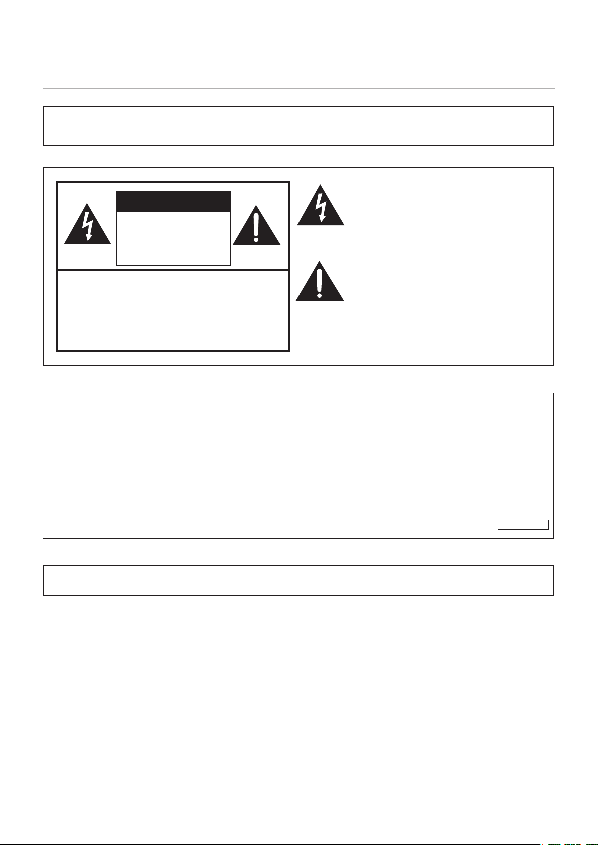
1. Install the remote control batteries
1. Place your nger on the part marked with the
p
, and then pull the cover off.
2. See the instructions in the compartment and put in the supplied batteries (R03
(“AAA” size) x 2) with their plus (+) and minus (-) sides oriented correctly.
3. Close the cover.
NOTE: • When the batteries become exhausted, replace them with new (commercially available) batteries.
• The supplied batteries may become exhausted quickly depending on how they are stored.
• If you will not be using the remote control for a long time, remove the batteries.
• Use manganese or alkaline batteries only.
8
2. Connect external equipment
• To protect the external equipment, disconnect the power cord of the monitor before making connections.
• Refer to the user’s manual of your equipment for further information.
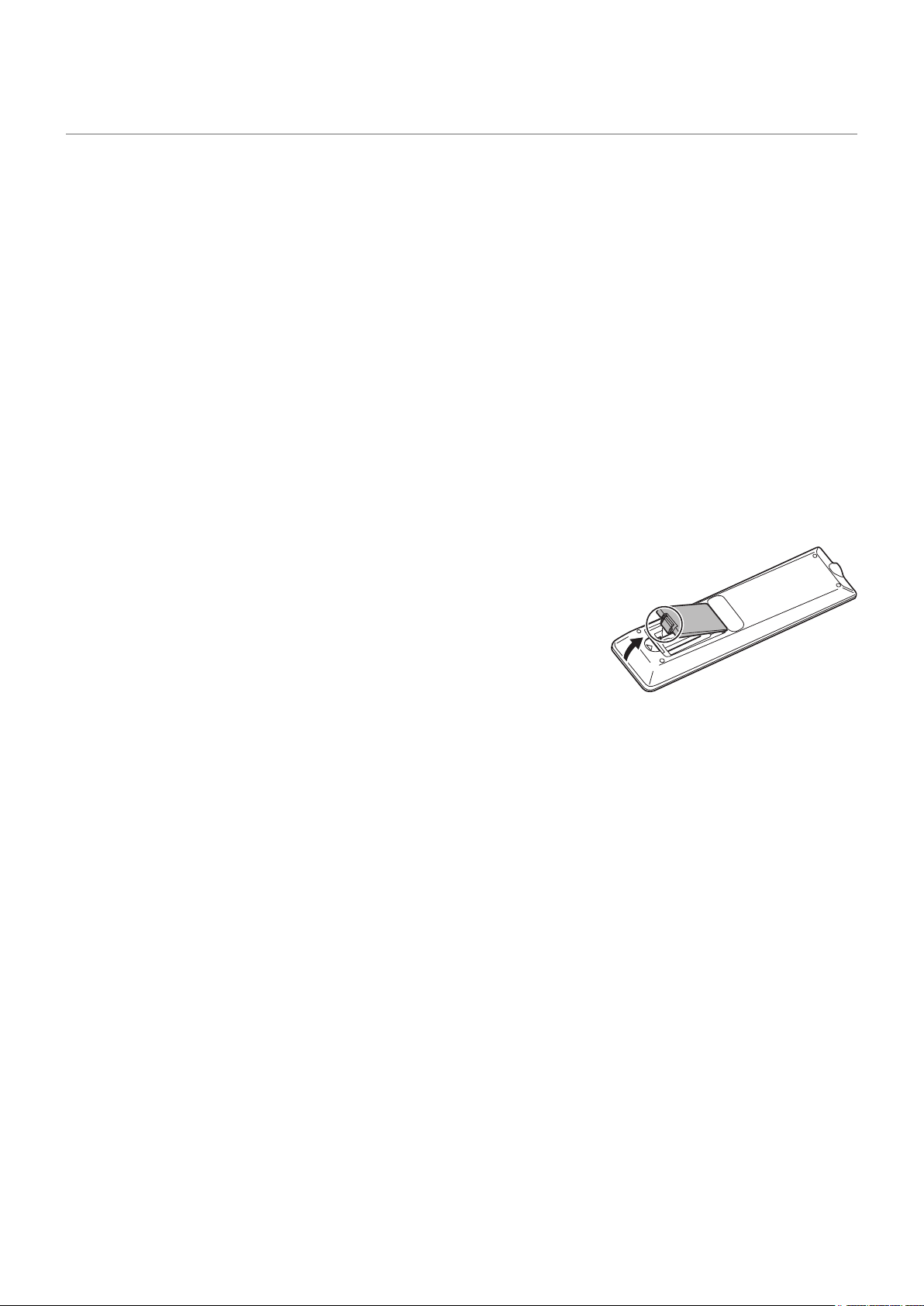
• The supplied cable clamps can be used to clamp the cables connected to the back of the monitor.
• Attach the supplied cable clamps (afxing type) to a at surface, removing any dust or dirt before attaching.
• Do not attach over a vent.
Cable clamp
(affixing type)
Affixing point
Cable
NOTE: Do not connect or disconnect the power cable when the monitor’s main power or other external equipment’s power
is turned on.
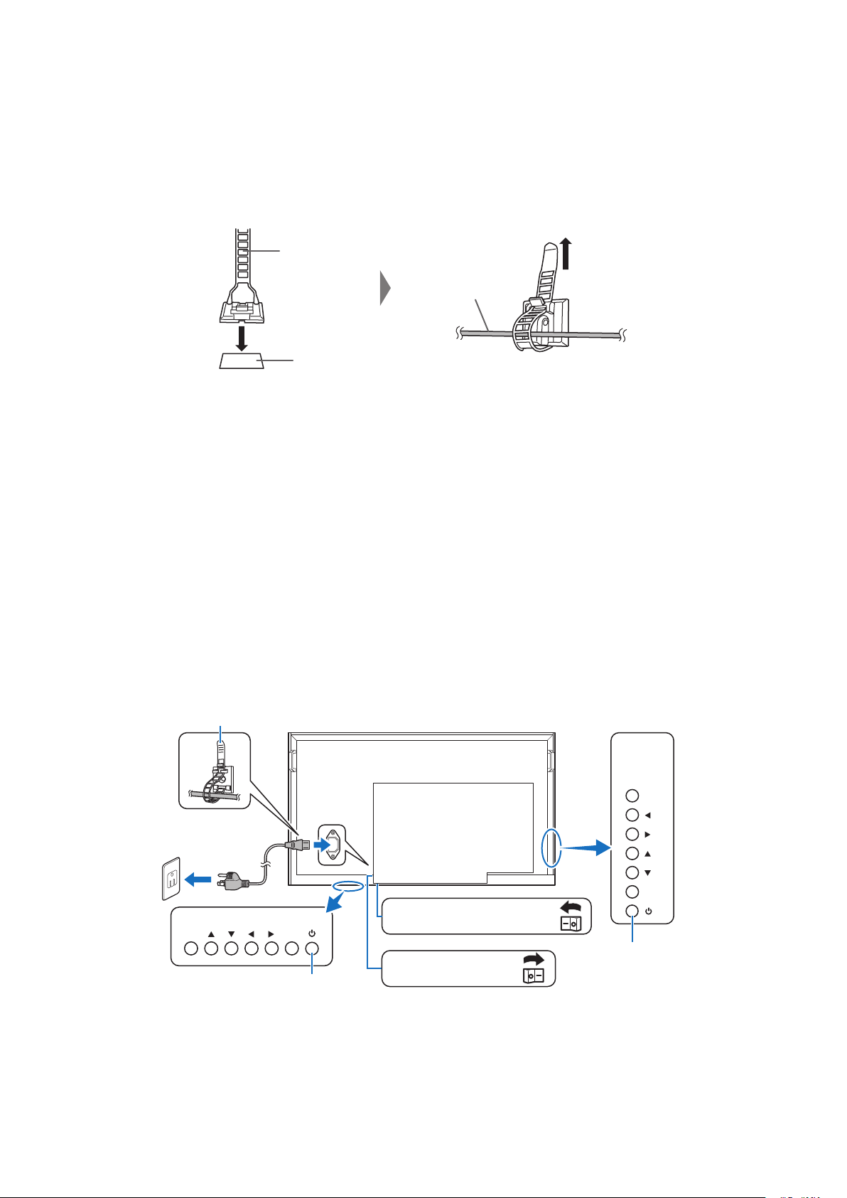
3. Connect the supplied power cord
NOTE: • Make sure that enough power is supplied to the monitor.
• The main power must be turned on/off with the main power switch. Do not connect/disconnect the power cord or
turn the breaker on/off while the main power switch is on.
• For a complete electrical disconnection, pull out the main plug.
• Connect the power cord to the monitor before plugging it into the power outlet.
• The power outlet shall be installed near the equipment and shall be easily accessible.
1. Connect one extremity of the power cord to the power input terminal of the monitor.
Plug it completely inside.
2. Connect the power plug to an AC power outlet.
INPUT
MENU
INPUT MENU
PN-HE751/
PN-HC861/
PN-HC751
PN-HE651/PN-HC651
Main power switch
(PN-HE651/PN-HC651)
Main power switch
(PN-HE751/PN-HC861/PN-HC751)
Cable clamp
POWER button
POWER button
9
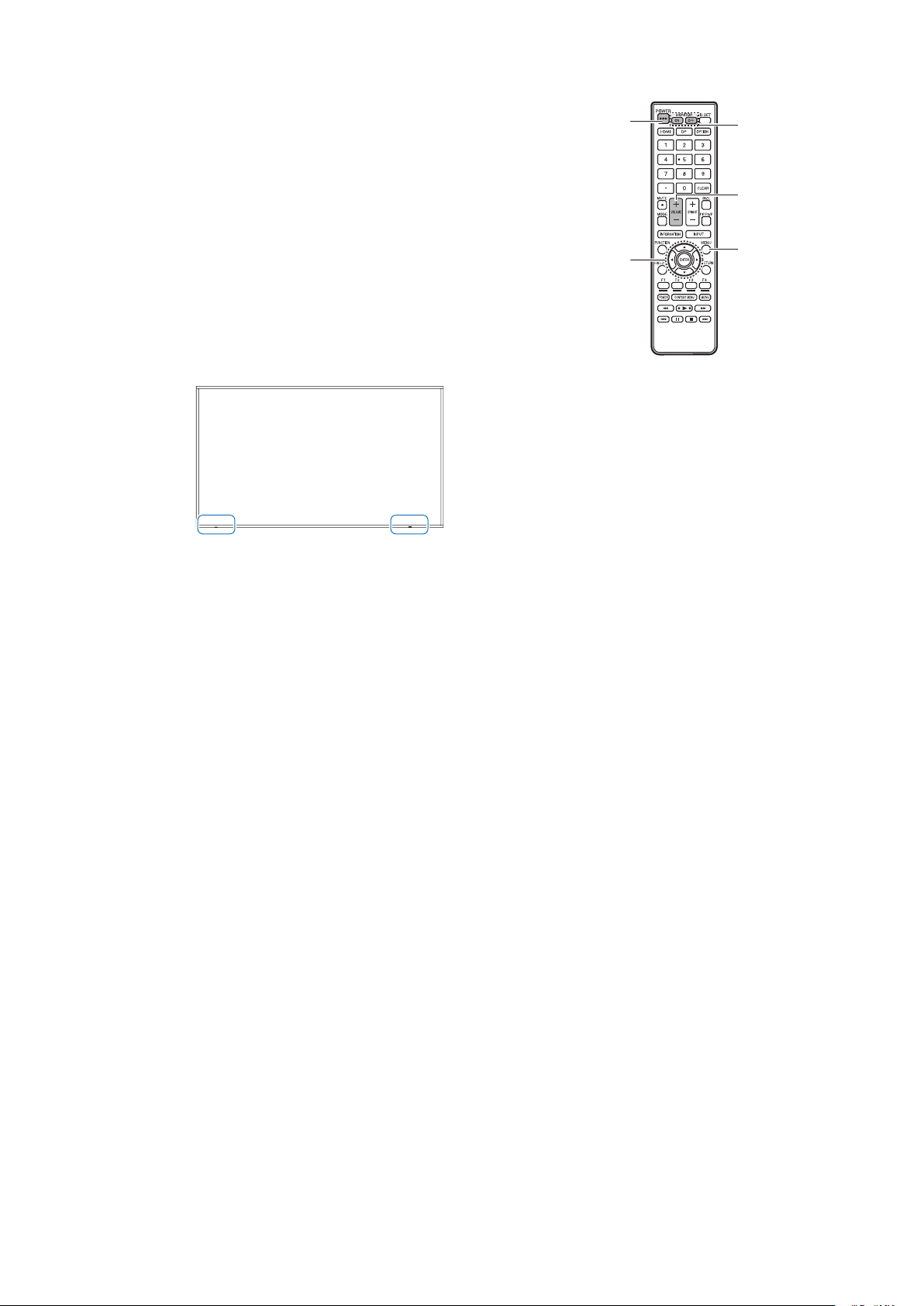
4. Turning on the main power
1. Turn on the main power switch.
2. Press the POWER button to turn the power ON/OFF.
You can also turn the power ON/OFF by pressing the
MONITOR ON button/MONITOR OFF button on the remote
control unit.
When switching the main power switch or the POWER button
off and back on, always wait for at least 5 seconds.
A short interval may result in a malfunction.
Turn on the monitor rst before turning on the computer or
playback device.
Remote control sensor
Be careful not to damage the remote control sensor during installation.
Remote control sensor
PN-HE751/PN-HC861/PN-HC751
Remote control sensor
PN-HE651/PN-HC651
Time setting
When the monitor is turned on for the rst time after being shipped from the factory, the [Setup Wizard] screen will be
displayed. Sets the time and language settings with the
p
,
t
or
u
button.
The time can be set in the OSD menu under [Schedule] -> [Current Time settings].
The language can be set in the OSD menu under [Setup] -> [OSD Settings] -> [Language].
5. Operate the connected external equipment
Select the input source for the monitor to display the video from the external equipment on the screen.
6. Adjust the sound
Make volume adjustments when required.
7. Adjust the picture settings
When using an HDMI input terminal, select the appropriate setting between [Mode 0], [Mode 1], and [Mode 2] in [EDID]
under [HDMI Settings] in the [Setup] OSD menu.
POWER
button
MENU
button
VOLUME +/-
(Volume adjustment)
button
MONITOR
button
ENTER button,
Cursor button

10
Mounting (for Customer)
Contact your supplier as they may be able to provide a list of qualied installation professionals. Mounting the product on a wall
or ceiling and hiring a technician are the customer’s responsibility.
Maintenance
• Periodically check for loose screws, gaps, distortions, or other problems that may occur with the mounting equipment. If a
problem is detected, refer to the qualied personnel or the supplier for service.
• Depending on the environment, the mounting location may weaken due to natural degradation. Regularly ask the qualied
personnel to inspect the mounting location and carry out maintenance.
Our company assumes no responsibility regarding any damage that may be caused by inadequate installation, misuse,
modication of the product, natural disasters, or other such causes.
When asking the qualied personnel for installation, inform them of the precautions mentioned in “Mounting Precautions (For
SHARP dealers and service engineers)”.
For long-term use
The backlight used for this monitor has a limited life and its brightness decreases with the usage time.
Also, if the same still image is shown for a long time, “Image Persistence” may occur. “Image Persistence” is a phenomenon
in which the image of an LCD remains visible after the image has been changed.
The “Image Persistence” is gradually eliminated by changing the screen, but if the same screen is shown for too long, the
“Image Persistence” will not disappear.
To avoid shortening the monitor’s lifetime, consider the following:
• Turn off the main power of the monitor when not in use.
• Use the
button on the main unit or the POWER button on the remote control to put the monitor in standby mode.
• In the OSD menu, go to [Setup] -> [Power save settings] -> [Energy Mode] -> and select [Home] or [Ofce]. When there is
no input signal, the monitor will automatically switch to power save mode.
• If you cover the panel surface of the main unit with a protective cover made of glass or acrylic, the panel surface will be
sealed and the internal temperature will rise.
Use the computer’s power management function or reduce the monitor’s brightness to prevent the internal temperature
from rising.
• Use [Schedule] in the OSD menu to automatically turn the monitor on or in Standby state as required.
NOTE: When using the schedule function, be sure to set [Current Time settings] in the [Schedule] OSD menu.
11
Mounting Precautions (For SHARP dealers and service engineers)
When installing, removing or moving the monitor, ensure that this is carried out by at least 4 people. (PN-HE651/PN-HC651 at
least 2 people.)
Be sure to use a wall-mount bracket designed or designated for mounting the monitor.
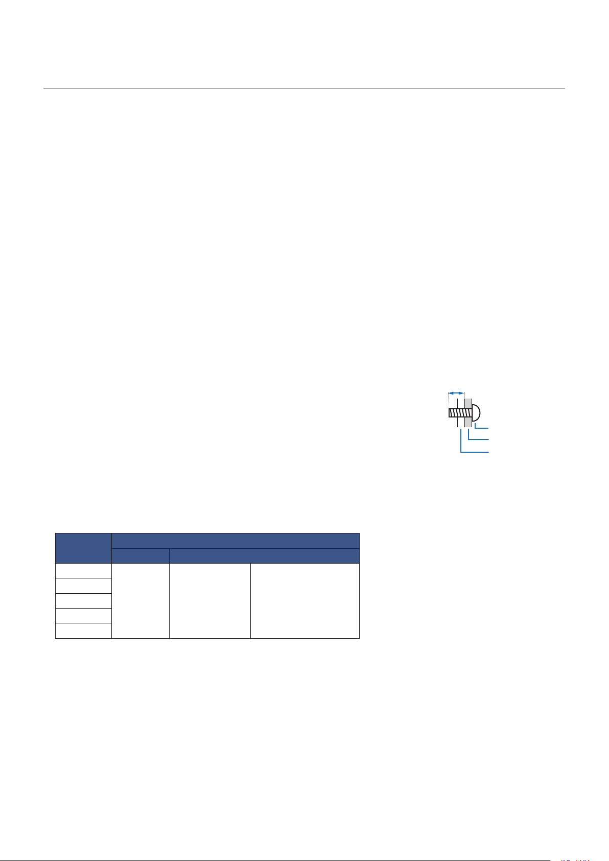
To attach a VESA-compliant mounting bracket, use M8 screws that are 3/8 inch (10 mm) to 1/2 inch (12 mm) longer than the
thickness of the mounting bracket.
This monitor and bracket must be installed on a wall which can endure at least 4 times or more the weight of the monitor.
Install by the most suitable method for the material and the structure.
Do not use an impact driver.
When moving the monitor, be sure to hold it around the periphery. Do not grasp the screen. This may cause product damage,
failure, or injury.
If you need to temporarily place the monitor on a table or other surface during installation, spread a thick soft cloth on the table
to prevent damage to the screen and table.
After mounting, please carefully ensure the monitor is secure, and not able to come loose from the wall or mount.
Do not use any screw holes other than those for mounting brackets, located on the rear of the monitor, for installation.
The product warranty does not cover damage caused by improper installation, re-modeling, or natural disasters.
Failure to comply with these recommendations could result in voiding the warranty.
Pay attention not to obstruct the air vents with the mounting brackets.
Mounting bracket
• When using commercially-available mounting brackets, make sure that they comply
with the VESA Flat Display Mounting Interface Standard (FDMI).
• Prior to mounting, inspect the installation location to ensure that it is strong enough
to guaranty safety.
• Pay attention not to obstruct part of the air vents of the monitor with the brackets.
• For detailed information, refer to the instructions included with the mounting
equipment.
• There are 4 installation holes on the back. Mount the monitor evenly at the four locations.
(See [Mounting on Walls or Ceilings] for installation.)
• Use screws of the sizes mentioned below to x the brackets to the monitor. Tighten the screws securely.
Screw Size
(A) (B)
PN-HE751
M8
3/8-1/2 inch
(10-12 mm)
+Mounting bracket
PN-HE651
PN-HC861
PN-HC751
PN-HC651
Monitor mounting
Screws (M8)
3/8 - 1/2 inch (10-12 mm)
Mounting bracket
12
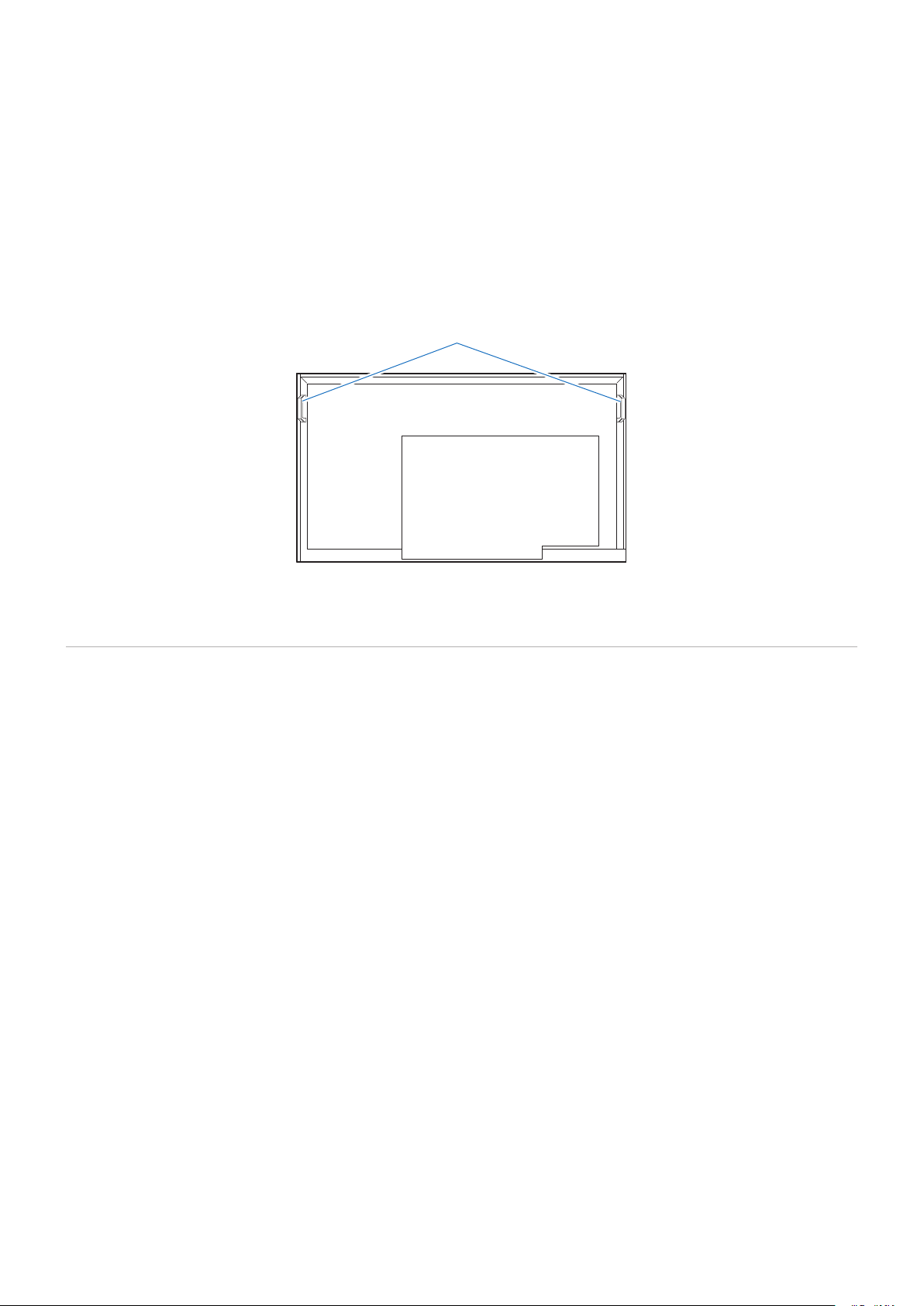
Installing a safety wire
When installing the monitor to a wall or a ceiling, use commercially-available wall or ceiling mounting brackets, but also a safety
wire.
When attaching the safety wire to the monitor’s handle, use the handle locations shown in the gure below.
Possible locations for the handles used to attach the safety wire
Attach the safety wire to the handles shown in the gure below.
Safety wire for horizontal installation
Mounting Location
NOTE: Allow for adequate ventilation or provide air conditioning around the monitor, so that heat can properly dissipate
away from the monitor and from the mounting equipment.
13
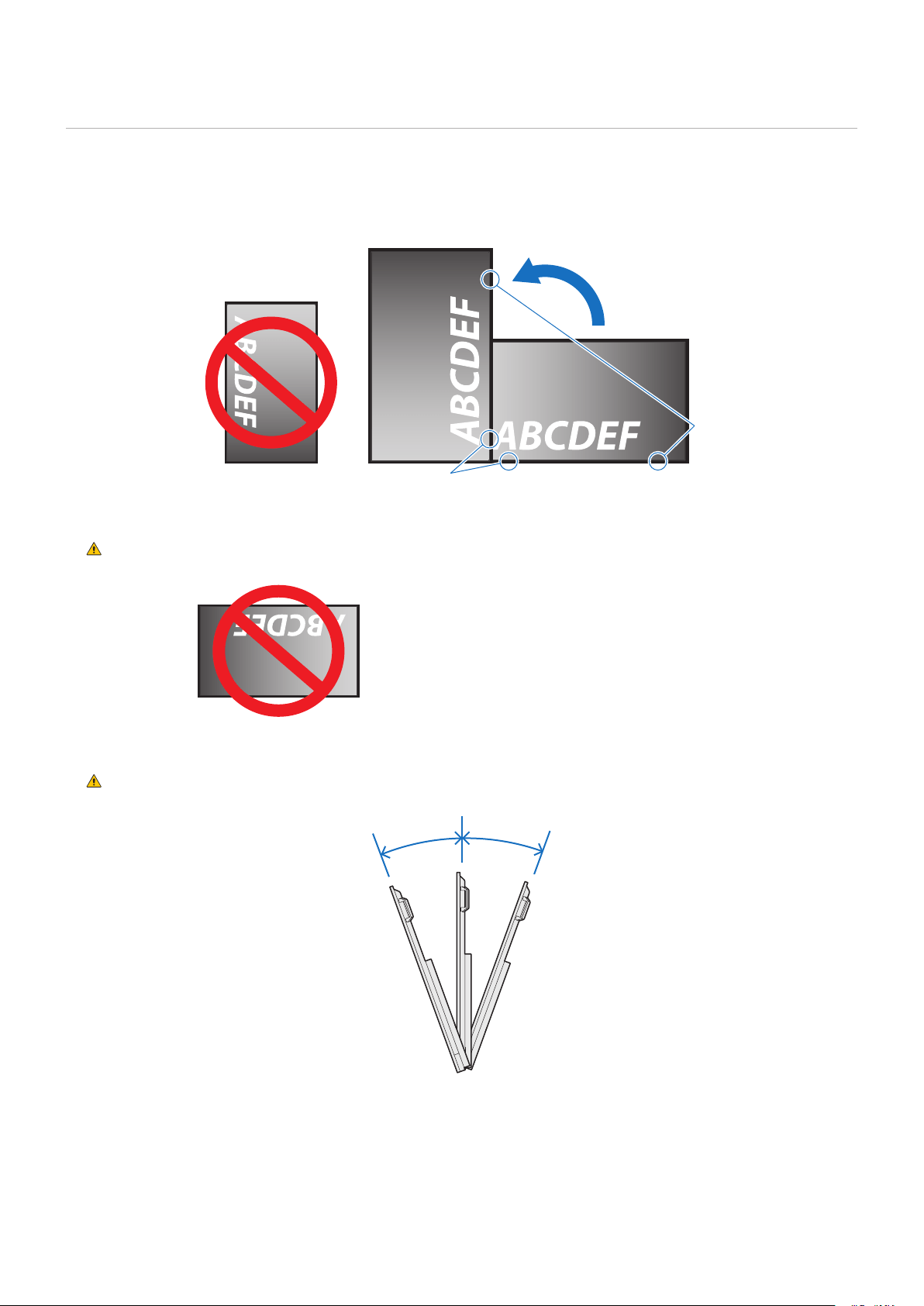
Orientation
When using the monitor in a vertical installation, be sure to rotate it counterclockwise so that the right side is on the upper side
and the left side is on the bottom.
If installed in the wrong direction, heat may be trapped inside the monitor and the life of the display may be shortened.
The monitor cannot be mounted upside down.
Power LED
(PN-HE751/PN-HC861/PN-HC751)
Power LED
(PN-HE651/PN-HC651)
WARNING: Do not install the monitor upside down.
The monitor cannot be used when inclined 20° or more.
WARNING: Installing the monitor at an angle of 20° or more may cause a malfunction.
Within 20°Within 20°
14
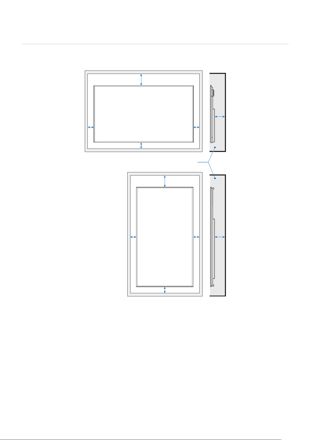
Ventilation Requirements
When mounting the monitor in an enclosed space or recessed area, leave adequate room between the monitor and the
enclosure to allow heat to disperse, as shown below.
For the monitor in landscape orientation
≤
104 °F (40 °C)
2 inch (50 mm)
2 inch (50 mm)
2 inch (50 mm)
7-7/8 inch (200 mm)
1-5/8 inch (40 mm)
2 inch (50 mm)
2 inch (50 mm)
2 inch (50 mm)
7-7/8 inch
(200 mm)
1-5/8 inch (40 mm)
NOTE: The maximum environmental operating temperature of the monitor is 104°F (40 °C).
This monitor has internal temperature sensors.
NOTE: If the monitor overheats, a “Warning!!” appears. If a “Warning!!” appears, stop using the monitor, turn off the power
and allow it to cool.
For more information on this function, see “Thermal Management” (page 73).
If the monitor is used in an enclosed area or if the LCD panel is covered with an acrylic protective sheet, check the
temperature around the monitor.
For the monitor in portrait orientation
15
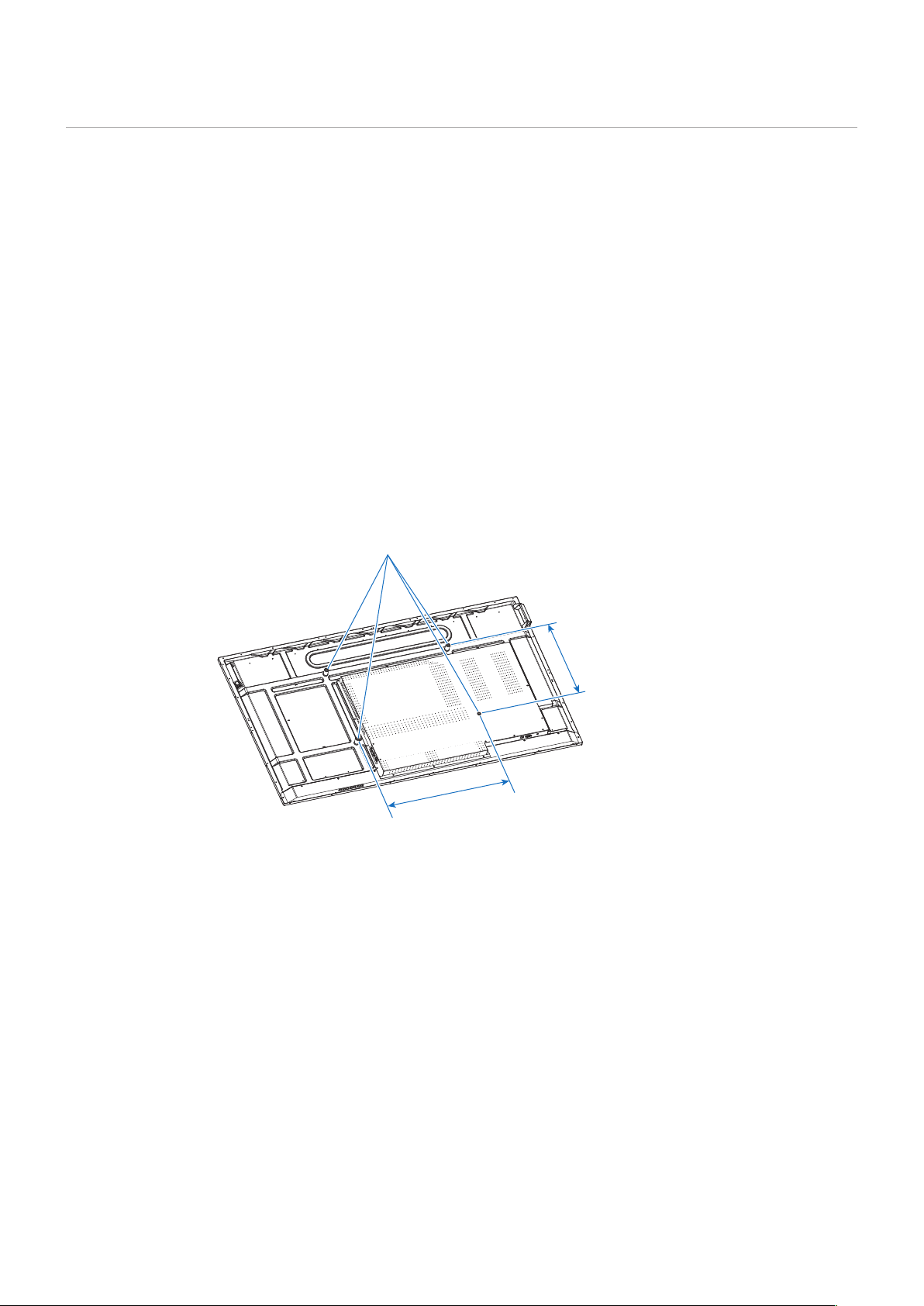
Mounting on Walls or Ceilings
Precautions when mounting the monitor on a wall or a ceiling
Be sure to read this section before mounting the monitor on a wall or a ceiling to guarantee safety.
• It may not be possible to mount the monitor on some walls or ceilings depending on their structure or strength. Ask the
qualied personnel or the supplier to check the mounting location.
Installation method
1. Place a soft cloth on the table or another at location where the monitor will be laid.
NOTE: • Make sure that the surface where you will lay the monitor is larger than the monitor screen.
• When installing, do not apply excessive force to any part of the monitor by pushing or leaning on it. This may
deform the monitor.
2. Place the monitor on top of the soft cloth.
3. Install the commercially-available mounting brackets.
PN-HE651/PN-HC651
4 installations holes M8
15-3/4 inch
(400 mm)
600 mm
(23-5/8 inch)
16
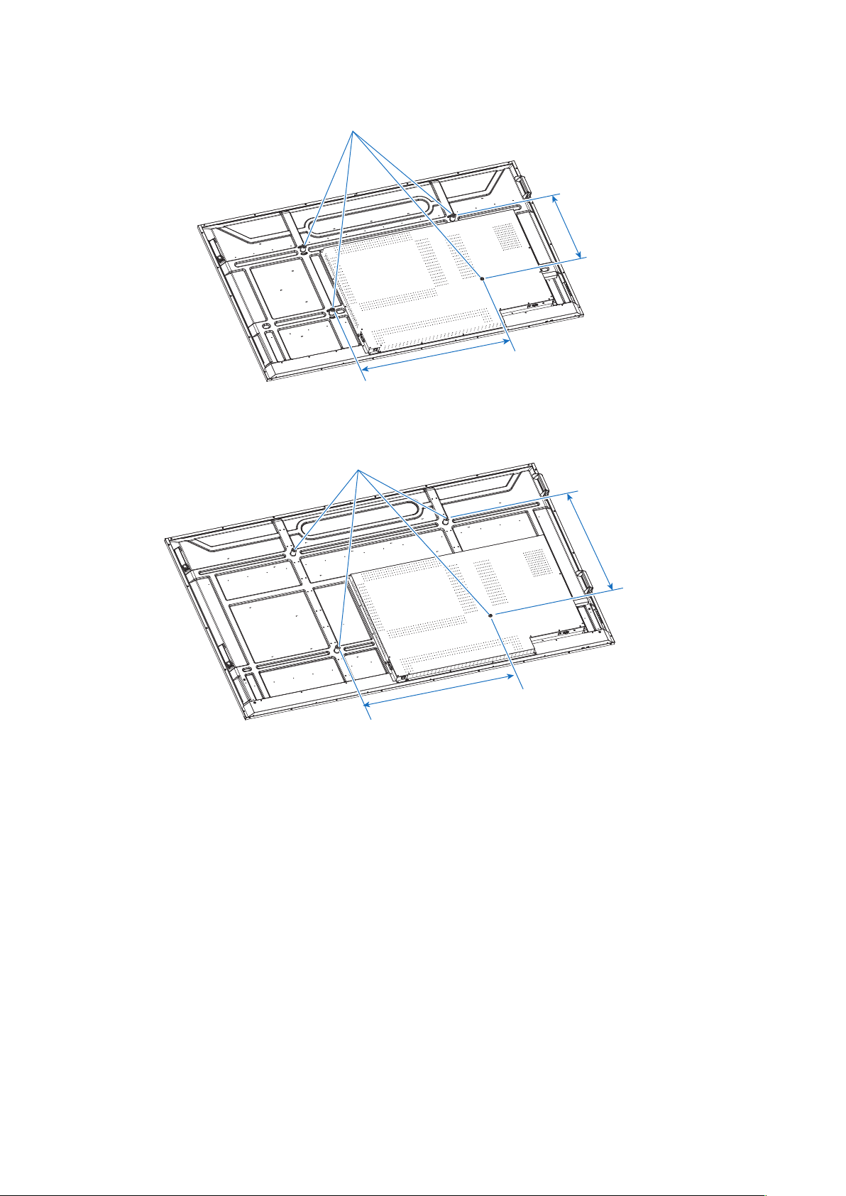
PN-HE751/PN-HC751
4 installations holes M8
15-3/4 inch
(400 mm)
31-1/2 inch
(800 mm)
PN-HC861
4 installations holes M8
23-5/8 inch
(600 mm)
31-1/2 inch
(800 mm)

17
Chapter 2 Parts Names and Functions
This Chapter Includes:
>
"Control Panel" on page 18
>
"Terminal Panel" on page 19
>
"Wireless Remote Control" on page 20
18
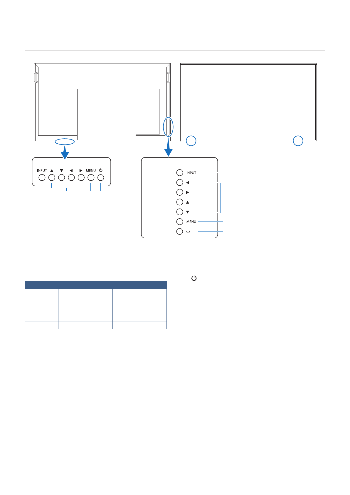
❶
INPUT Button
Serves as a settings button to make selections when the
OSD screen is displayed.
When the OSD screen is not displayed, the input switching
menu is displayed.
Input mode Video Audio
HDMI1 HDMI1 input terminal HDMI1 input terminal*
1
HDMI2 HDMI2 input terminal HDMI2 input terminal*
1
HDMI3 HDMI3 input terminal HDMI3 input terminal*
1
VGA D-sub input terminal Audio input terminal
Media Player USB port USB port
*1: You can change the [Audio in] in the [Audio Input] settings.
❷
Arrow Keys
Left/Right: Move to the right or left of the OSD control
menu.
Moving the left/right keys left and right
increases or decreases the adjustment
values.
Up/Down: Move up and down in the OSD control menu.
Pressing the left/right keys when the OSD menu is closed
directly adjusts the volume.
❸
MENU Button
Opens the OSD menu.
Returns to the previous OSD menu.
❹
Button (power button)
Switches between power on and off (standby mode).
❺
Power LED/Remote control sensor
(PN-HE751/PN-HC861/PN-HC751)
❻
Power LED/Remote control sensor
(PN-HE651/PN-HC651)
This is the signal receiver of the remote control unit.
There is a power LED in the same position.
Normal operation (On mode): Green lit *
2
Input signal waiting state: Red ashing
Standby state (Off): Red lit
*2: If [Off] is selected in [Setup]-> [Other Settings]-> [LED
Indicator] in the OSD menu, the power LED is turned off.
Control Panel
❶ ❷ ❸ ❹
❶
❷
❸
❹
❺ ❻
PN-HE651/PN-HC651 PN-HE751/PN-HC861/PN-HC751
19
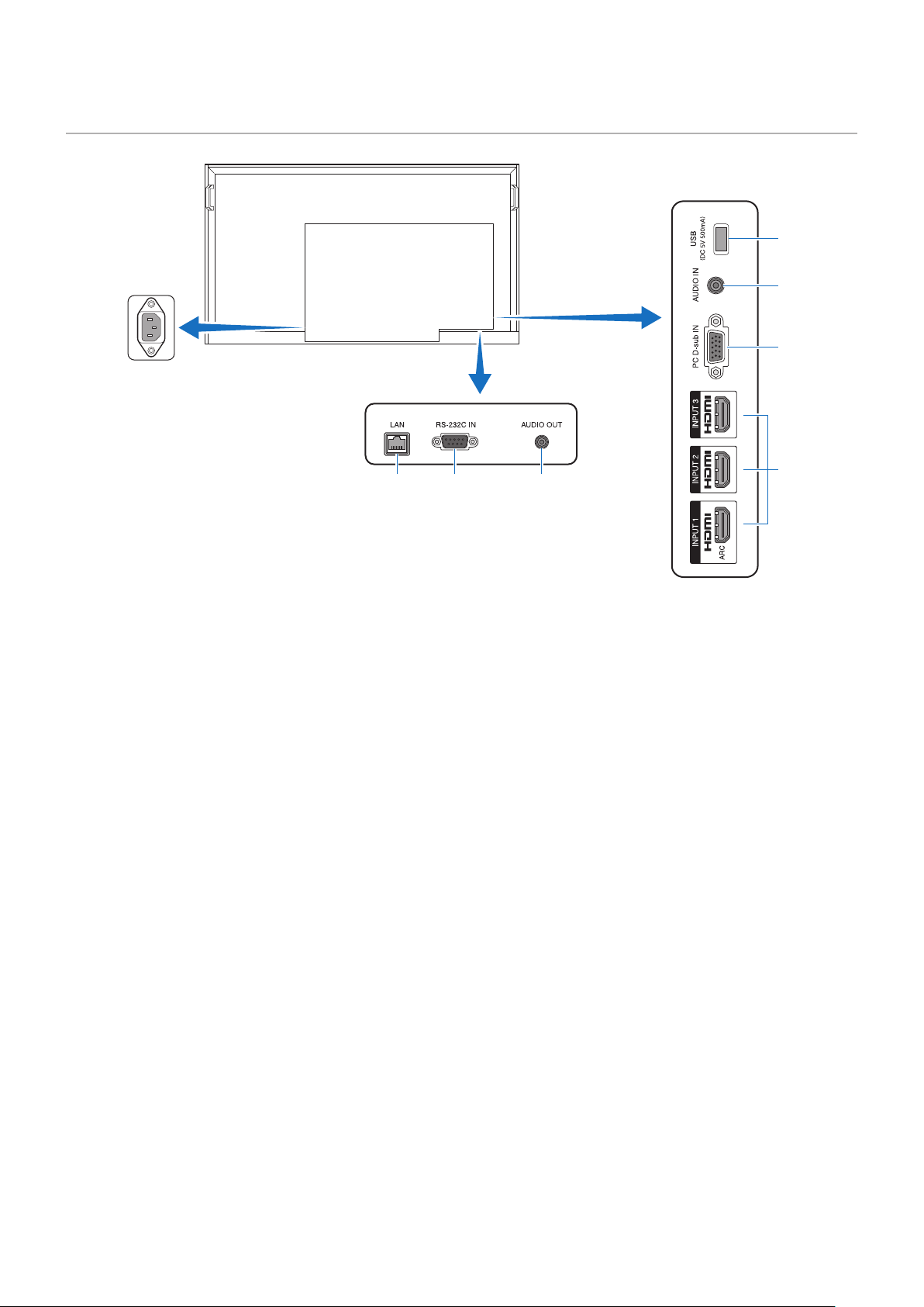
Terminal Panel
❶ ❷ ❸
❹
❺
❻
❼
❶
LAN port (LAN terminal)
Use the HTTP server function and a Web browser on a
computer to manage the LAN settings of the monitor.
Receives control commands from the computer.
NOTE: When you use a network, your communication
data is exposed to the risks of being stolen or
illegally accessed. To avoid these risks, you
need to use this monitor in a secure network
environment.
❷
RS-232C input terminal
For connection to a computer. Receives control commands
from the computer.
❸
AUDIO OUT terminal (Audio output terminal)
Outputs the selected audio signal.
❹ USB Type-A port (USB port)
Can be used to display photos (still images) and play video
and music les stored in a USB storage device.
Check the shape of the connectors when connecting a USB
storage device or USB cable.
❺
AUDIO IN terminal (Audio input terminal)
For connection to the audio output terminal of a computer or
another device.
❻
VGA input terminal (D-sub input terminal)
For connection to the video output terminal (analog) of a
computer.
❼
HDMI input terminals (HDMI1 (ARC)/HDMI2/HDMI3)
For connection to devices with digital video interface
complying with the HDMI standard. HDMI1 terminal also
supports ARC (Audio Return Channel) for audio output.
Connect an HDMI cable supporting ARC to this terminal.
Connect audio devices supporting ARC to the HDMI1 (ARC)
terminal.
NOTE: ARC sends the monitor’s sound to the audio
equipment from the HDMI1 ARC terminal.
20
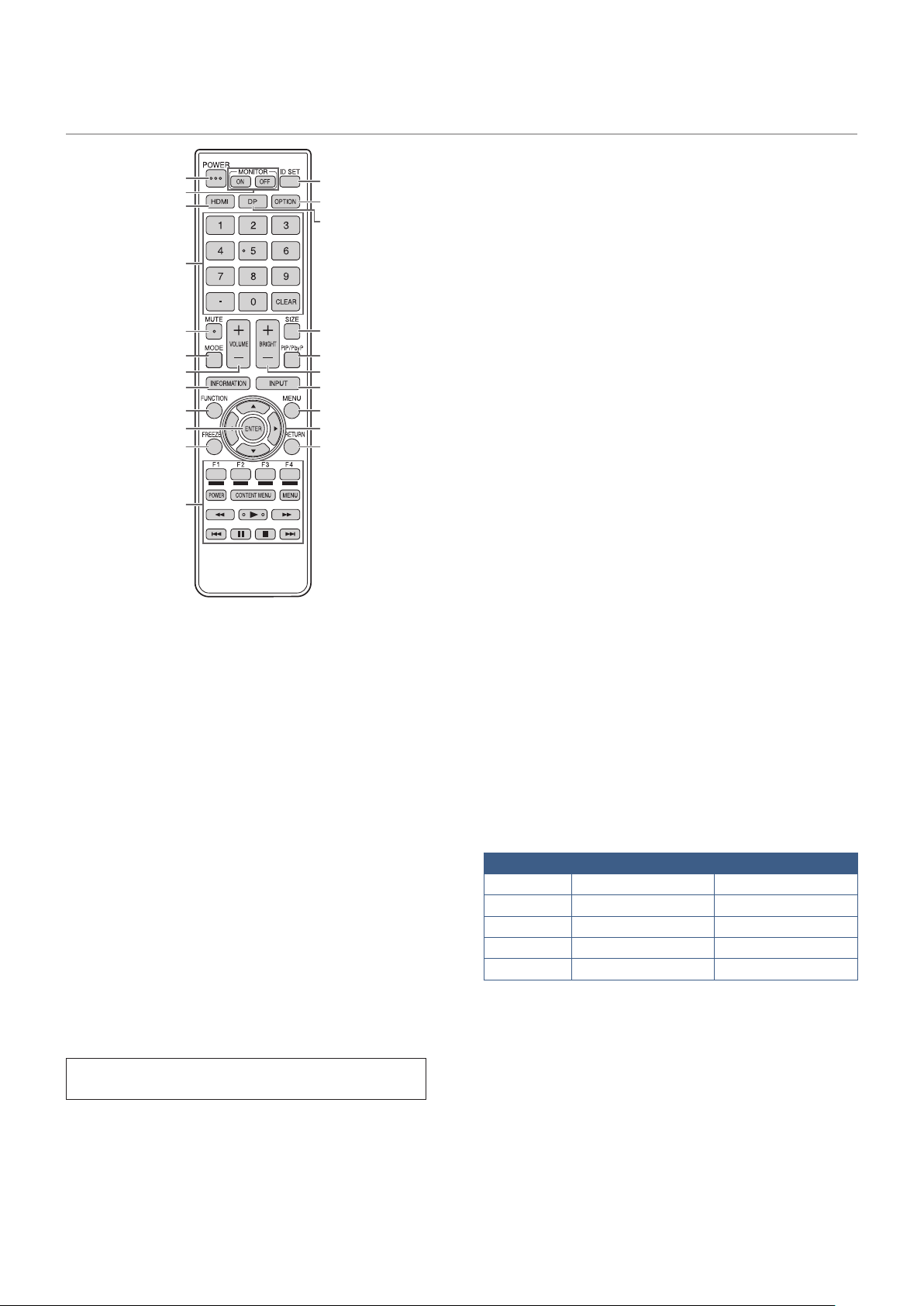
Wireless Remote Control
❸
❶
❾
⓫
⓬
⓰
⓱
⓯
⓳
⓭
❻
❺
❽
❿
❹
❷
❼
⓮
⓲
⓴
❶
POWER button
Press the POWER button to turn the power ON/OFF.
❷
MONITOR buttons
You can also turn the power ON/OFF by pressing the MONITOR
ON button/MONITOR OFF button on the remote control unit.
NOTE: When the main power switch is off, the monitor
cannot be turned on.
❸
HDMI button
Switch the input mode to HDMI1, HDMI2 or HDMI3.
❹
Numeric input buttons
When CEC in the HDMI Settings menu is set to On, use
these buttons to operate the device connected through the
HDMI interface.
❺
MUTE button
Silences the audio and video.
Press the button again to restore the previous volume and
video.
❻
MODE button (picture mode selection)
Each time you press this button, the color mode changes in
the following order:
HDR Video -> Dynamic -> Standard -> Conferencing ->
HighBright -> Custom -> HDR Video...
❼
VOLUME button +/- (Volume adjustment)
Press + or - to adjust the volume.
❽
INFORMATION button
Displays monitor information.
❾
FUNCTION button
This is not used with this monitor.
❿
ENTER button
Conrms the setting.
⓫
FREEZE button
Freezes the video shown on the monitor.
In some cases a residual image may occur. Do not freeze
the video for a long time.
⓬
Buttons for MEDIA PLAYER or operating the HDMI-
connected device
• This is used in MEDIA PLAYER.
• When CEC in the HDMI Settings menu is set to On, use
these buttons to operate the device connected through
the HDMI interface.
⓭
ID SET button
This is not used with this monitor.
⓮
OPTION button
This is not used with this monitor.
⓯
DP button (DisplayPort)
This is not used with this monitor.
⓰
SIZE button (Changing aspect ratio)
Selects the aspect ratio of the image between [Normal],
[1:1], [Full], and [Zoom].
⓱
PIP/PbyP button
This is not used with this monitor.
⓲
BRIGHT button +/- (Brightness adjustment)
Press + or - to adjust the brightness.
⓳
INPUT button (Input mode selection)
The menu is displayed. Press the up/down keys to select
the input mode, and press the ENTER button to enter.
Input mode Video Audio
HDMI1 HDMI1 input terminal HDMI1 input terminal*
1
HDMI2 HDMI2 input terminal HDMI2 input terminal*
1
HDMI3 HDMI3 input terminal HDMI3 input terminal*
1
VGA (RGB) D-sub input terminal Audio input terminal
Media Player USB port USB port
*
1
You can change the [Audio in] in the [Audio Input] settings.
⓴
MENU
button
Opens the OSD menu.
Returns to the previous OSD menu.
㉑
Cursor buttons
These buttons are used to perform operations such as selecting
items, changing adjustment values, and moving the cursor.
㉒
RETURN button
Returns to the previous OSD menu.

21
Chapter 3 Connections
This Chapter Includes:
>
"Wiring Diagram" on page 22
>
"Connecting to a Personal Computer" on page 23
>
"Connecting to a Media Device with HDMI" on page 24
>
"HDMI-CEC Command" on page 26
>
"Internal Video Sources" on page 27
>
"Media Player" on page 27
>
"Connecting a USB Device" on page 28
Before making connections:
• Turn off the power of the monitor, the computer and the external equipment before connecting the monitor to the computer.
• Refer to the externals equipment’s user manuals for available connection types and instructions for each piece of
equipment.
NOTE: • When the audio output connector of the connected audio device or computer is a stereo mini jack, use an audio
cable without a resistor.
• Using an audio cable with a built-in resistor may make it impossible to increase the volume or mute the sound.
• We recommend turning off the monitor’s main power before connecting or disconnecting a USB storage device.
• Do not connect or disconnect cables when the monitor’s main power or other external equipment’s power is
turned on.
22
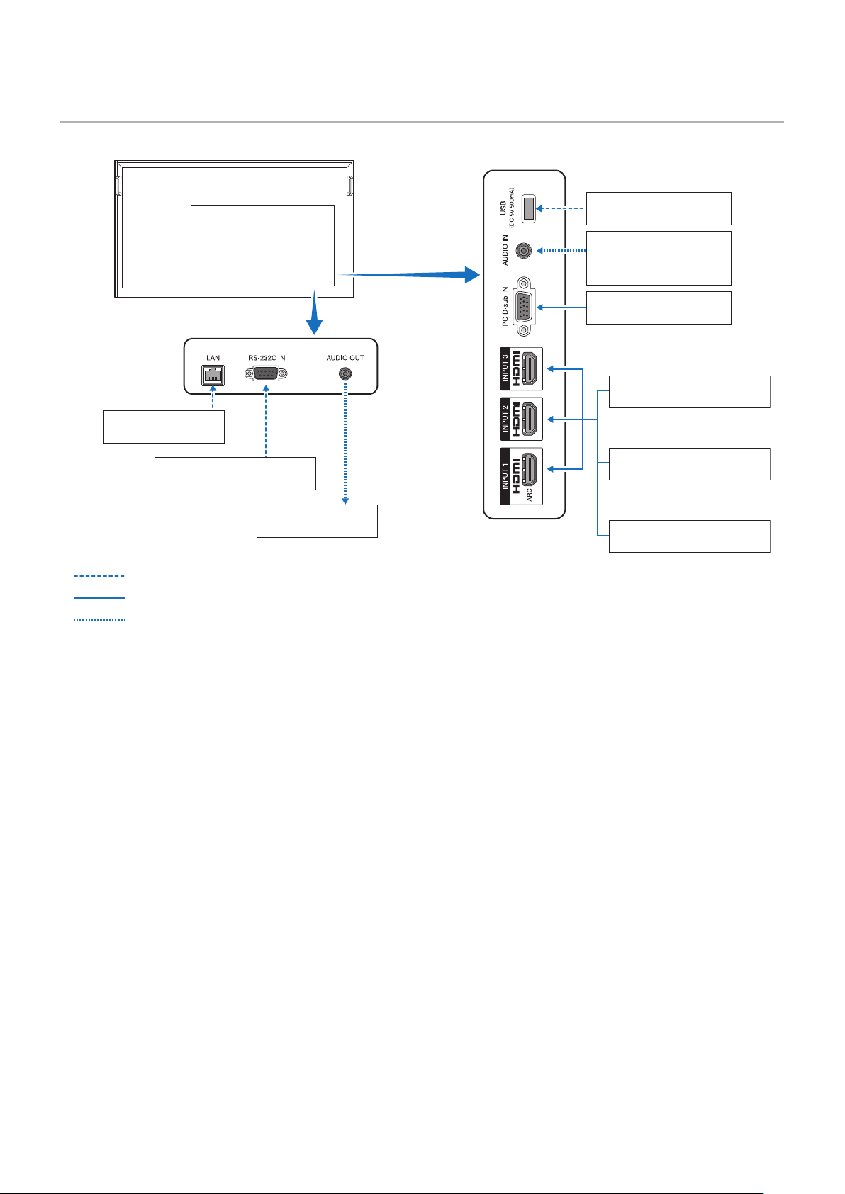
Wiring Diagram
Computer (D-sub)
Computer (RS-232C)
Computer (HDMI)
Computer (stereo mini jack)
Video player
(stereo mini-jack)
USB port (USB storage
device)
Video player (HDMI)
Blu-ray or DVD player (HDMI)
Stereo amplier
: Other signals
: Video signal
: Audio signal
Network

23
Connecting to a Personal Computer
Connecting to a Computer with HDMI
The monitor can be connected to and used with video players and computers equipped with an HDMI output. For more
information, refer to the user’s manual of the player or the other devices.
• Use an HDMI cable with the HDMI logo.
• It may take a moment for the signal to appear after turning on the device outputting the HDMI signal.
• Depending on the video card or driver used, the image may not be shown correctly.
• When you use a computer with HDMI, go to the OSD menu [Video] -> [Advanced Video] and set [Overscan] to [Auto] or
[Off].
• If the monitor’s main power is turned on after the connected computer has been turned on, the image may not be
displayed. In this case, turn off the computer then turn it on again.
• If the source signal is 4K (50 Hz/60 Hz), HDCP 2.2 or HDR, got to the OSD menu [Setup] c [HDMI Settings] -> [EDID] and
set [Mode 2]. If the monitor cannot be displayed correctly, set to [Setting 0] or [Setting 1].
• When inputting a 4K signal, use a high-speed or premium high-speed HDMI cable.

24
Connecting to a Media Device with HDMI
The monitor can be connected using a single HDMI cable to Blu-ray players, streaming media players, or game consoles for the
highest picture and audio quality. 4K UHD content is shown when the connected media player also supports 4K content.
Supports HDCP (High-bandwidth Digital Contents Protection) coding, a type of digital rights management that prevents high-
denition content, in Blu-ray discs, DVDs and streaming media, from being copied or broadcast illegally.
NOTE: • Supports 1080p, 1080i, 720p@50 Hz/60 Hz, 480p@60 Hz, 576p@50 Hz, 480i@60 Hz, 576i@50 Hz,
3840×2160 (24 Hz/25 Hz/30 Hz [Mode 1] [Mode 2]), 3840×2160 (50 Hz/60 Hz [Mode 2]), 4096×2160 (24 Hz/25
Hz/30 Hz [Mode 1]), 4096×2160 (50 Hz/60 Hz [Mode 2]).
• Connect the HDMI cable when both the media player and the monitor are powered off.
• Use an HDMI cable with the HDMI logo.
• Some HDMI cables and devices may not show the image correctly due to different HDMI specications.
• With the implementation of HDCP, there may be cases in which certain content is protected by HDCP and might
not be displayed. This is not a malfunction.
Connecting to Audio Equipment with ARC Function
When audio equipment with the ARC function is connected to the HDMI1 (ARC) terminal of the monitor using the ARC-
supported HDMI cable, the speakers connected to the audio equipment outputs the monitor’s sound.
• The sound output via HDMI1 (ARC) is not adjustable with the OSD menu.
• When the ARC function is activated, the monitor’s internal speakers are muted.
• The sound of the video displayed on the screen is output to the audio equipment via the HDMI1 (ARC) terminal. Audio
signals not supported by the input terminal used for the video being displayed are not output by the HDMI1 (ARC)
terminal. Refer to “Specications” for the supported signal of each input terminal.
HDMI-CEC (Consumer Electronics Control)
HDMI-CEC provides compatible video devices connected via HDMI with the ability to communicate and allows limited control
between the device and the monitor. For example, playing a Blu-ray player can immediately switch input to the Blu-ray player
without using the remote control. Not all devices are fully compatible, and, in some cases, the media device manufacturer may
only provide compatibility with its own monitors or TVs. See “HDMI-CEC Command” (page 26).
When supported, the monitor’s remote control can be used to control the video device.
NOTE: The instructions in this section guide you through conguring [CEC] in the monitor’s OSD menu.

25
Enabling CEC
1. Connect an HDMI-CEC compatible device to the HDMI terminal.
Press the HDMI button of the remote control.
2. Press the MENU button to open the OSD menu.
3. In the OSD menu, go to [Setup] -> [HDMI Settings] -> [CEC] -> and select [On] in [CEC].
4. In the OSD menu, go to [Setup] -> [HDMI Settings] -> [CEC] -> [Device list] and press the ENTER button of the remote
control.
When the device search is complete, connected devices are shown by their names.
If no HDMI-CEC compatible device is found, make sure the device is connected, turned on, that it supports CEC, and that
CEC is enabled. Depending on the manufacturer, the CEC feature may have a different name. Refer to the device’s user
manual.
5. Press the RETURN button of the remote control.
26
HDMI-CEC Command
Connect an HDMI-CEC compatible device to the HDMI terminal.
OSD menu HDMI-CEC
command name
Explanation Setting
CEC
(Consumer
Electronics
Control)
One Touch Play When an HDMI-CEC compatible
deviceis played, the monitor connected
to the device with an HDMI cable also
automatically turns on. After the monitor
powers on, Input terminal automatically
switches.
If the monitor is already turned on,
the monitor connected to the HDMI-
CEC compatible device with an HDMI
cable also automatically turns on. After
the monitor powers on, Input terminal
automatically switches.
Setup
Move Select
HDMI1
CEC
Auto Turn Off
Audio Receiver
Device list
Off
OK
Return
MENU
EXIT
EXIT
On
In the OSD menu, go to [Setup] -> [HDMI
Settings] -> [CEC] -> and select [On] in
[CEC].
Remote Control Pass
Through
The monitor’s remote control button
operation can function with HDMI-CEC
compatible devices connected with an
HDMI cable.
For example, part of the HDMI-CEC
compatible device menu can be operated
using the remote control.
Power Status The connected HDMI-CEC compatible
devices can obtain the monitor’s power
status, such as if the monitor is in standby
mode or on.
System Information This function obtains information from a
connected HDMI-CEC compatible device
(CEC version, physical address, etc.).
Auto Turn Off System Standby If the monitor is set to standby using the
remote control, the HDMI-CEC compatible
device connected with an HDMI cable
also goes into standby at the same time.
If the monitor goes into standby while
an HDMI-CEC compatible device is
recording, the device remains on.
Refer to the user’s manual supplied with
the HDMI-CEC compatible device for
further information.
In the OSD menu, go to [Setup] -> [HDMI
Settings] -> [CEC] and select [Enable] in
[Auto Turn Off].
Audio
Receiver
System Audio
Control
Connect audio equipment with the ARC
function to the HDMI1 (ARC) terminal
using the ARC-supported HDMI cable.
The Volume buttons of the remote control
can control the volume of the connected
HDMI ARC audio equipment. While this
function is active, the monitor’s internal
speakers are automatically set to MUTE.
In the OSD menu, go to [Setup] -> [HDMI
Settings] -> [CEC] and select [Enable] in
[Audio Receiver].
Device list Device OSD Name
Transfer
This function is used to obtain the name
of the connected devices.
In the OSD menu, go to [Setup] -> [HDMI
Settings] -> [CEC] -> [Device list] and
press the ENTER button of the remote
control.
Routing Control By selecting a device name, the HDMI-
CEC compatible device input switches to
the input you selected. After selecting the
device, the remote control operates for
the selected device.
NOTE: Depending on the connected device, sometimes the device does not work properly.
27
Internal Video Sources
Media Player
The internal Media Player will play audio and video les that are stored on a USB storage device. The USB storage device
connects to the terminal panel on the side of the display. See page page 37 for instructions on using the Media Player.
Compatible USB Storage Devices
If the USB storage device connected to the monitor is not recognized, check its format. The USB storage device used with the
Media Player should be in the FAT32 or FAT16 format. For more information on how to format a storage device, see the manual
or the help section of your Windows
®
.
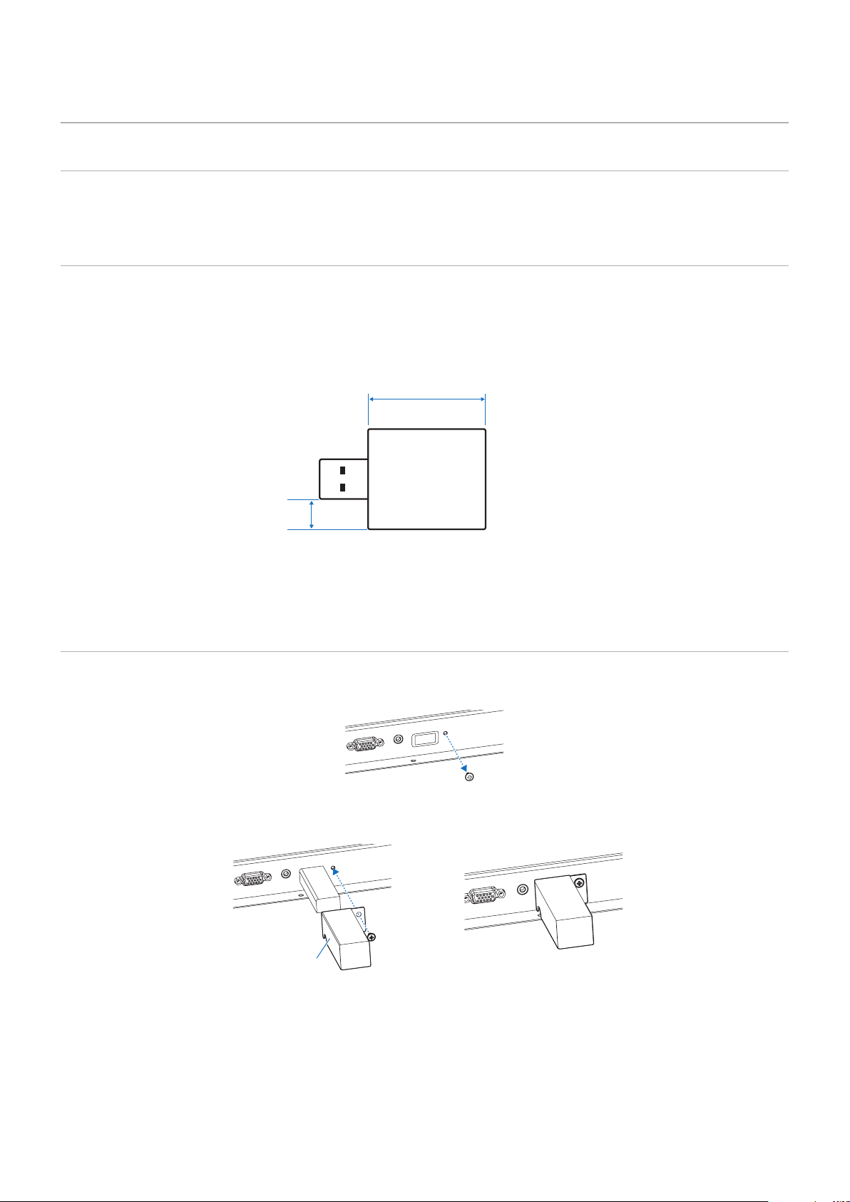
Use a USB storage device of the correct size in accordance with the drawing below.
Connect the USB storage device to the USB Type-A port of the monitor.
≤ 2-3/4 inch (70 mm)
≤ 3/16 inch (5 mm)
USB storage device
NOTE: • The monitor is not guaranteed to work with all USB storage devices sold commercially.
• Check that the USB storage device is connected to the USB Type-A port of the monitor.
Attaching the USB ash drive cover
We recommend that you attach a USB memory cover to prevent theft.
1. Remove the screw at the position shown in the gure.
2. Insert the USB ash drive into the USB port.
3. Attach the USB ash drive cover and secure with the screw removed in step (1).
USB ash drive
cover
28
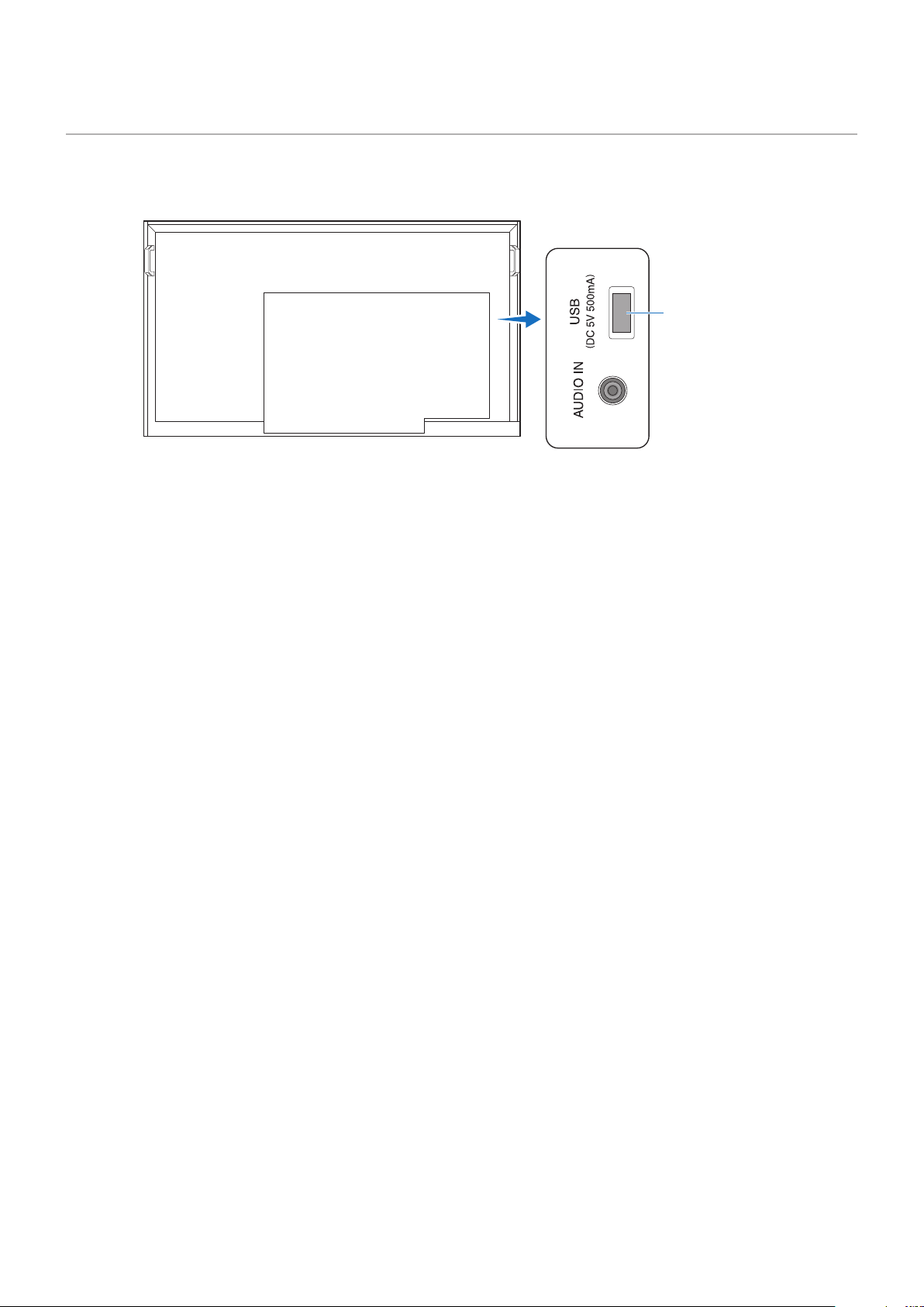
Connecting a USB Device
Connect a USB storage device to the USB Type-A of the monitor as shown in the gure below to display images and videos
using the Media Player function.
USB Type-A port
NOTE: • Check the connector shape and orientation when connecting the USB device or cable.
• Do not connect/disconnect a USB storage device to the monitor when the monitor is turned on. To prevent
damage to the monitor and possible corruption of the connected device’s data les, the monitor’s main power
switch should be off before making connections.

29
Chapter 4 Basic Operation
This Chapter Includes:
>
"Power On and Off Modes" on page 30
>
"Operating Range for the Remote Control" on page 32
>
"Showing the Information OSD" on page 33
>
"Switching Between Picture Modes" on page 33
>
"Setting the Aspect Ratio" on page 34
>
"OSD (On-Screen Display) Controls" on page 35
>
"Using the Media Player Menu" on page 37
30
Power On and Off Modes
Power indicator status
Mode Normal operation
(On mode)
Input signal waiting state Standby state
Power indicator Lit green Flashing green Lit red
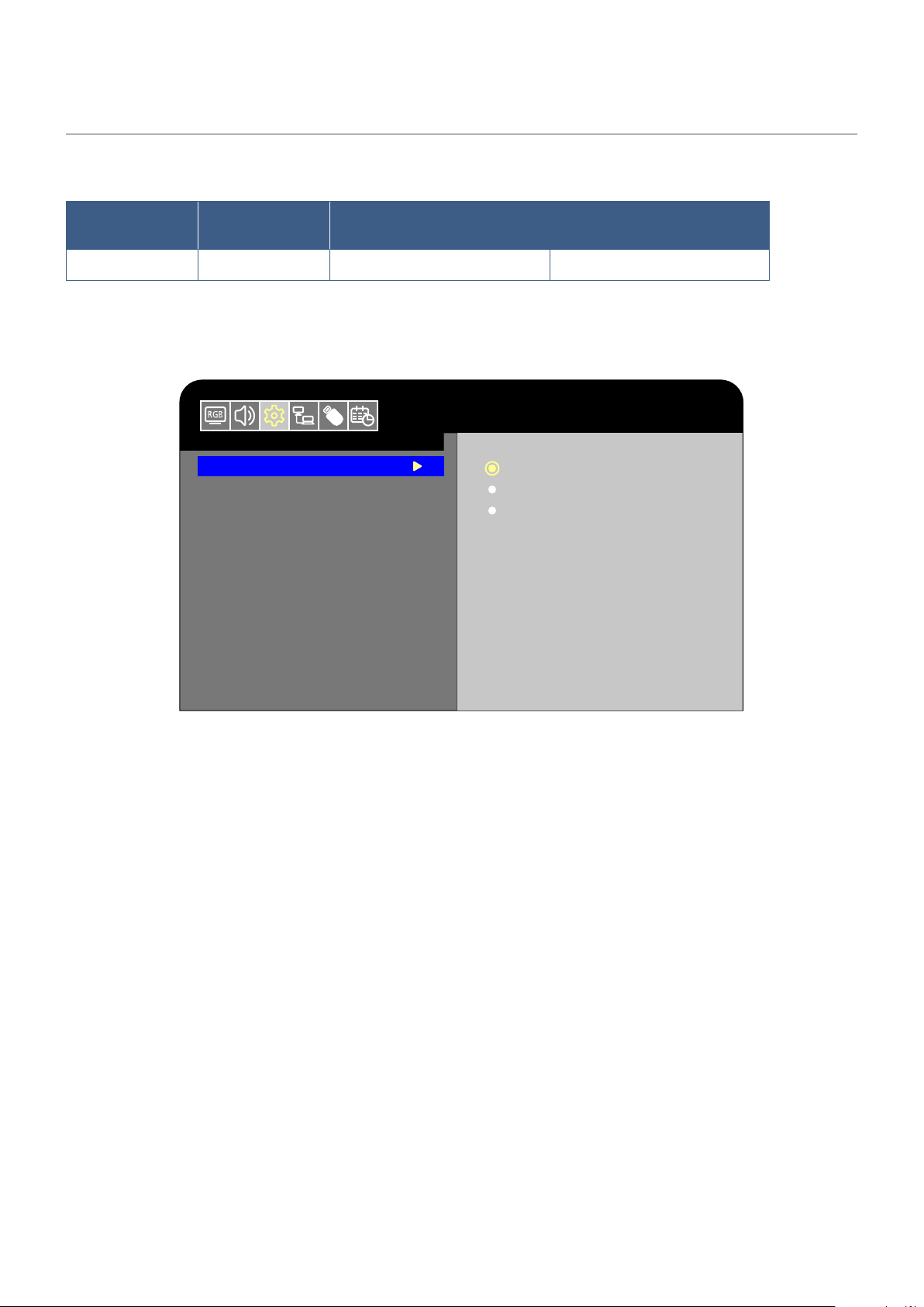
Energy Mode
The three following modes are available on the monitor.
Setup
HDMI1
Energy Mode
Clock
Auto Power Down
Home
Retail
Office
LAN and RS-232C can be selected for the monitor control. The way the energy modes operate varies depending on the
selected control method.
When [RS-232C] is selected for control
Home/Ofce mode
• When no signal is input, “No signal” is displayed and the monitor enters the Input signal waiting state after a while.
• When a signal is input into the selected input terminal, the On mode is resumed.
Retail mode
• The monitor does not enter the input signal waiting mode when no signal is input. (The On mode is maintained.)

31
When [LAN] is selected for control
Home mode
• When no signal is input, “No signal” is displayed and the monitor enters the Input signal waiting state after a while.
• If no LAN signal is input during signal standby, the monitor enters the input signal waiting mode in a low power after 3
minutes. You will not be able to connect to the LAN.
• Even if the monitor is turned off with the remote control unit and no LAN signal is input, it enters the input signal waiting
mode in a low power after 3 minutes.
• When a signal is input into the selected input terminal, the On mode is resumed.
Retail mode
• The monitor does not enter the input signal waiting mode when no signal is input. (The On mode is maintained.)
Ofce mode
• When no signal is input, [No signal] is displayed and the monitor enters the input signal waiting mode in a low power. You
will be able to connect to the LAN.
• When a signal is input into the selected input terminal, the On mode is resumed.
WARNING: If the monitor is not connected a LAN cable while in Home mode, the LAN will be turned off automatically. If
you control with LAN again, connect the LAN cable to the monitor and then turn on the power.
32
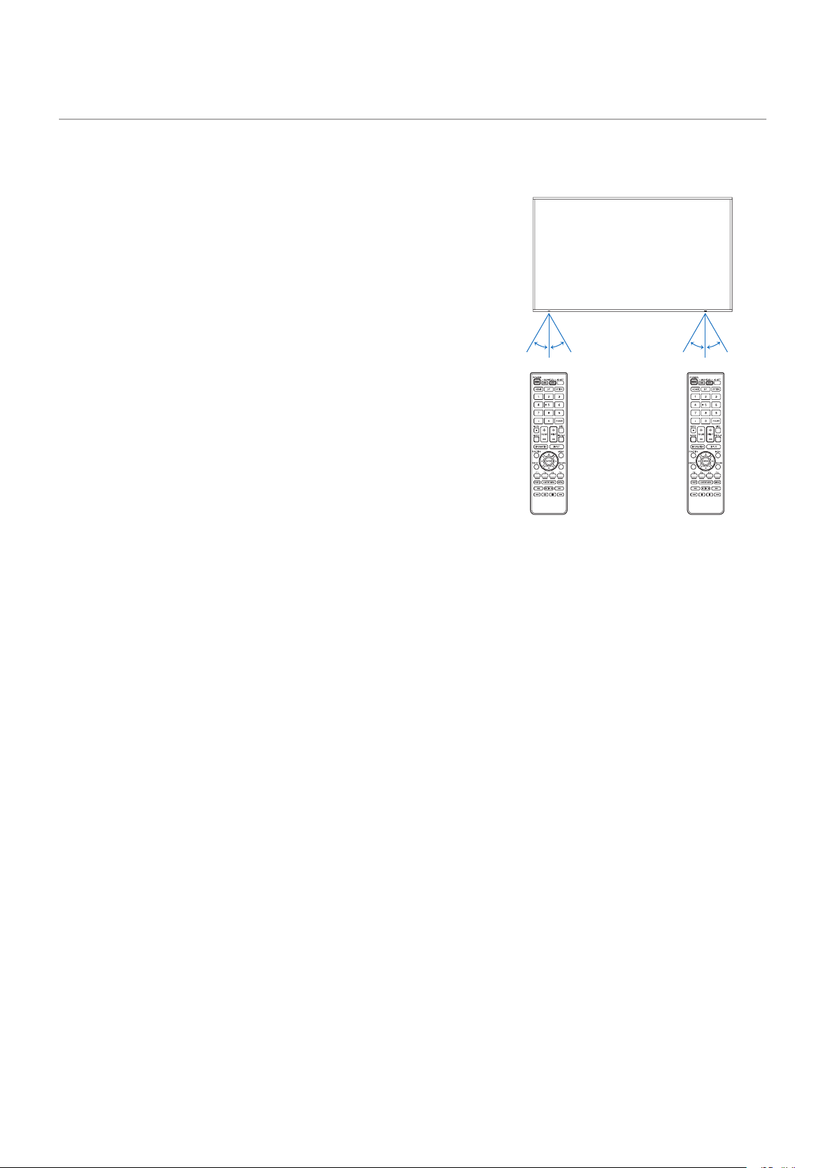
Operating Range for the Remote Control
Point the top of the remote control toward the monitor’s remote control sensor during button operation.
The operation range of the remote control unit is approx. 16.4 feet (5 m) at an angle of approx 10° from the center to the top/
bottom/right/left of the remote control sensor.
NOTE: The remote control system may not function when direct
sunlight or strong illumination strikes the remote control
sensor, or near uorescent lamps.
Handling the remote control
• Do not expose to strong shock.
• Do not allow water or other liquid to splash on the remote control.
If the remote control gets wet, wipe it dry immediately.
• Avoid exposure to heat and steam.
• Ask your supplier or your municipality for information on how to
dispose of the batteries.
• Do not open the remote control, except to install the batteries.
10°10°10°10°
PN-HE751/PN-HC861/PN-HC751 PN-HE651/PN-HC651

33
Showing the Information OSD
When the signal format changes during input switching, information such as the video input terminal, resolution information, and
IP address is displayed.
1 Input mode
2 Resolution
3 SDR / HDR information
4 IP address*
* When [Control Interface] in the [Control
Settings] menu is set to [LAN]:
White: Connected to a LAN
Red: Not connected to a LAN
HDMI1
3840X2160@30Hz
SDR
IP ADDRESS : 192.xxx.x.xx
2
3
4
1
NOTE: When the Input mode is [Media Player], the information OSD will not be displayed.
Switching Between Picture Modes
Press the MODE button of the remote control to change the Picture Mode setting between Dynamic, Standard, Conferencing,
HighBright, Custom, and HDR Video*.
* HDR Video can be selected only when an HDR signal is input.
34
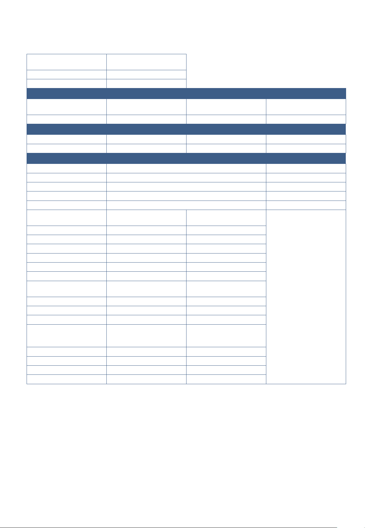
Setting the Aspect Ratio
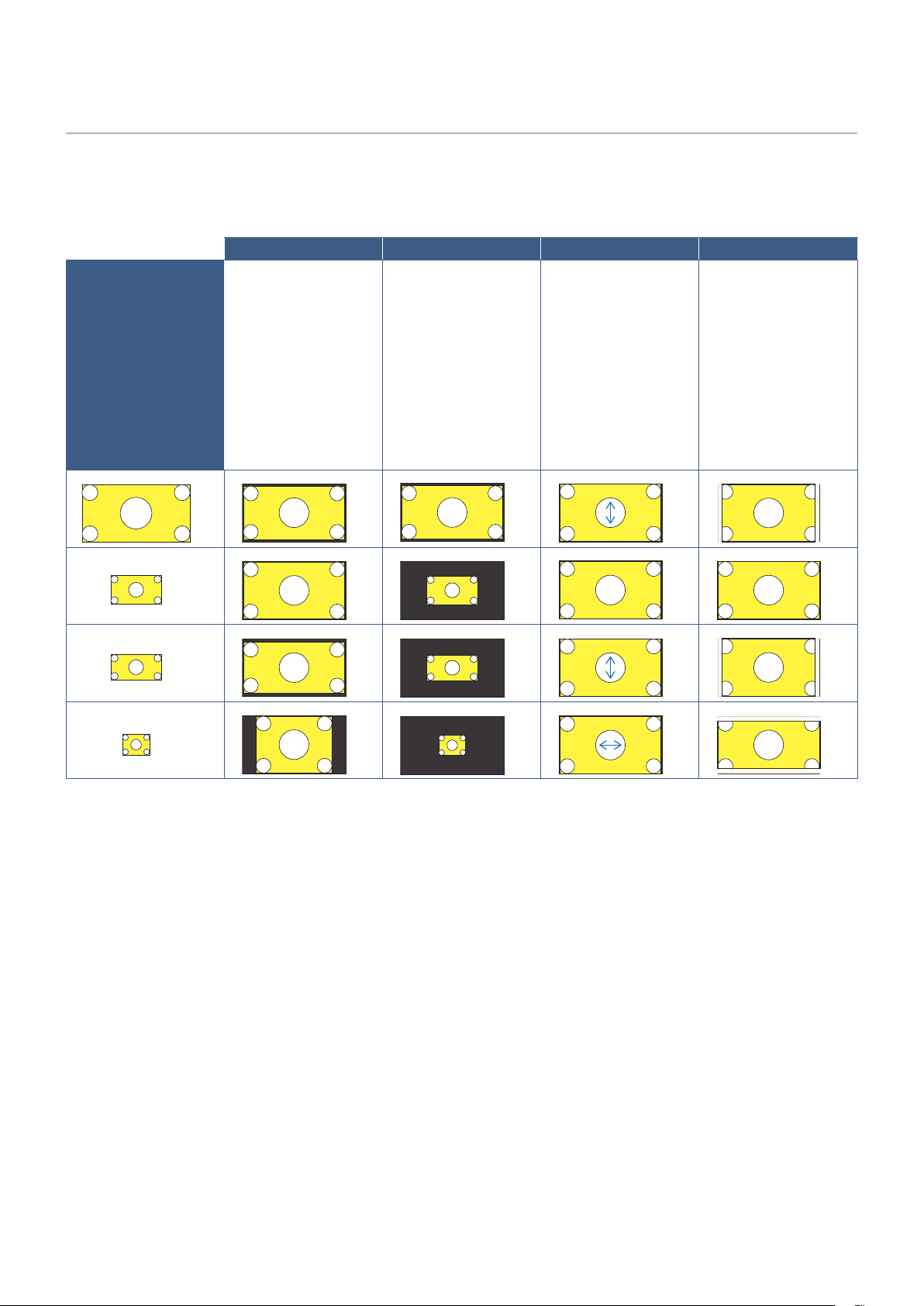
Press the SIZE button of the remote control to change the Aspect Ratio setting between Normal, 1:1, Full, and Zoom.
NOTE: This setting cannot be changed when [Media Player] is selected for the Input mode.
Normal 1:1 Full Zoom
Video signal
The aspect ratio of
the input signal is
maintained and the
image is enlarged/
reduced.
• Black bars are
added vertically or
horizontally.
• The screen is not cut,
neither vertically nor
horizontally.
The image is displayed
with the number of panel
pixels corresponding
to the resolution of the
input signal.
When the input signal
is larger than the
number of the panel
pixels, the aspect ratio
is maintained and the
image is reduced.
The aspect ratio of the
input signal is ignored
and the image is
enlarged.
• There are no black
bars, neither vertically
nor horizontally.
• The screen is not cut,
neither vertically nor
horizontally.
The aspect ratio of
the input signal is
maintained and the
image is enlarged.
• There are no black
bars, neither vertically
nor horizontally.
• Part of the image,
vertically or
horizontally, is not
displayed.
4096
2160
1920
1080
1920
960
1024
768
3840
2160
3840
1920
3840
2025
2880
2160
3840
2025
1920
1080
1920
960
1024
768
3840
2160
3840
2160
3840
2160
3840
2160
3840
2160
3840
2160
3840
2160
3840
2160
4096
2160
1920
1080
1920
960
1024
768
3840
2160
3840
1920
3840
2025
2880
2160
3840
2025
1920
1080
1920
960
1024
768
3840
2160
3840
2160
3840
2160
3840
2160
3840
2160
3840
2160
3840
2160
3840
2160
4096
2160
1920
1080
1920
960
1024
768
3840
2160
3840
1920
3840
2025
2880
2160
3840
2025
1920
1080
1920
960
1024
768
3840
2160
3840
2160
3840
2160
3840
2160
3840
2160
3840
2160
3840
2160
3840
2160
4096
2160
1920
1080
1920
960
1024
768
3840
2160
3840
1920
3840
2025
2880
2160
3840
2025
1920
1080
1920
960
1024
768
3840
2160
3840
2160
3840
2160
3840
2160
3840
2160
3840
2160
3840
2160
3840
2160
NOTE: Note that changing the aspect ratio to compress or stretch an image and display it publicly or for commercial
purposes in coffee shops, hotels, or other such places, may violate the rights of the copyright holder.
35
OSD (On-Screen Display) Controls
The monitor features an OSD (On-Screen Display) function that allows the user to easily adjust the screen.
By operating the menu displayed at the top of the screen, you will be able to adjust the brightness and the other screen settings.
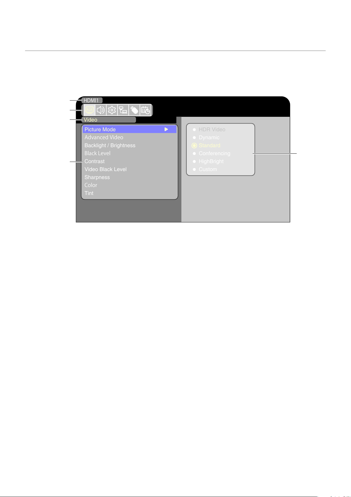
OSD screen structure The OSD screen is composed of the following elements.
Video
HDMI1
Picture Mode
AdvancedVideo
Backlight / Brightness
BlackLevel
Contrast
Video Black Level
Sharpness
Color
Tint
HDR Video
Dynamic
Standard
Conferencing
HighBright
Custom
Input mode
Selected
main menu
Sub menu
Adjustment
settings
Main menu icons
36
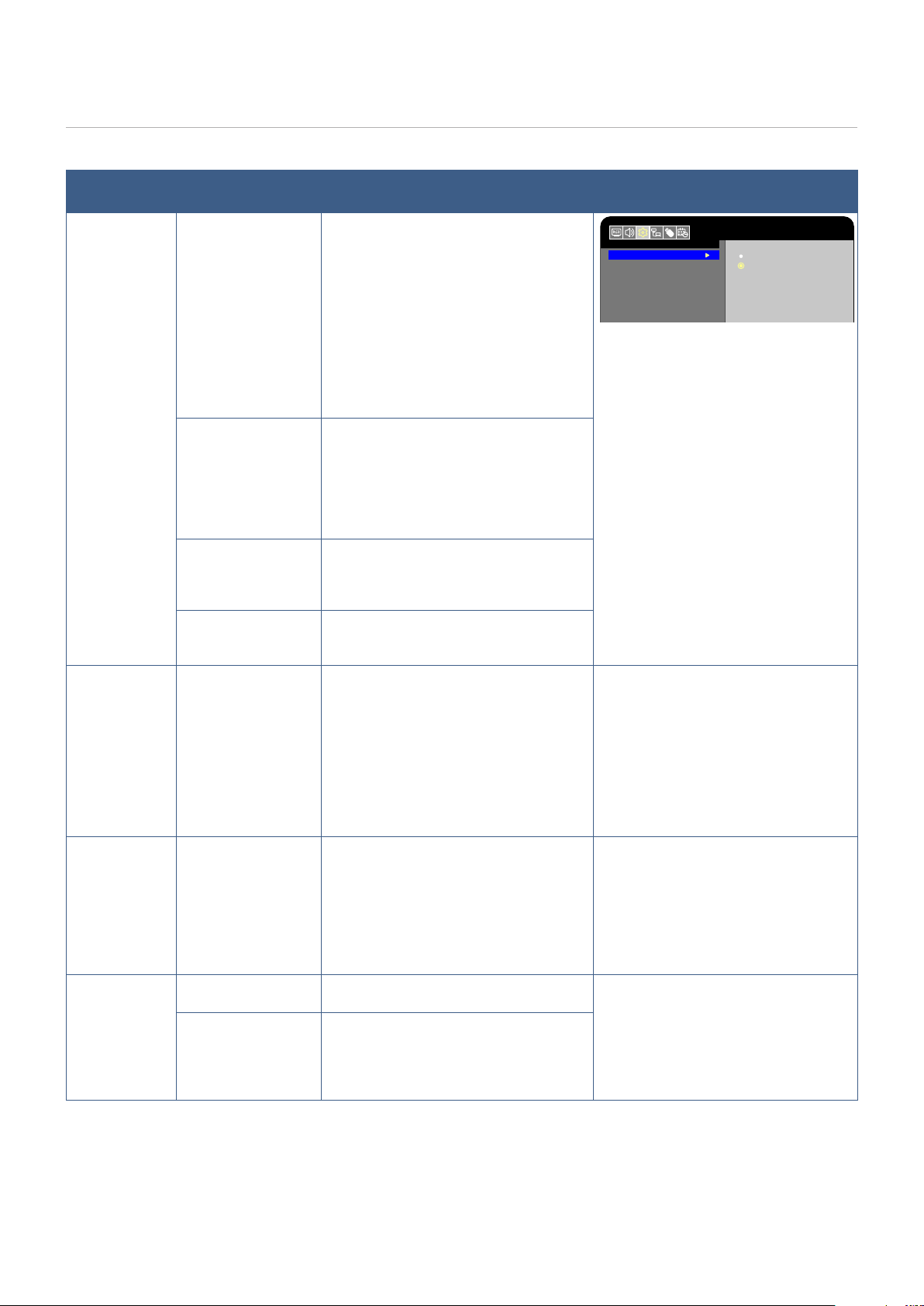
The function of each OSD menu element is briey explained below. For more details on the content of the menu, see “OSD
Controls List” (page 68).
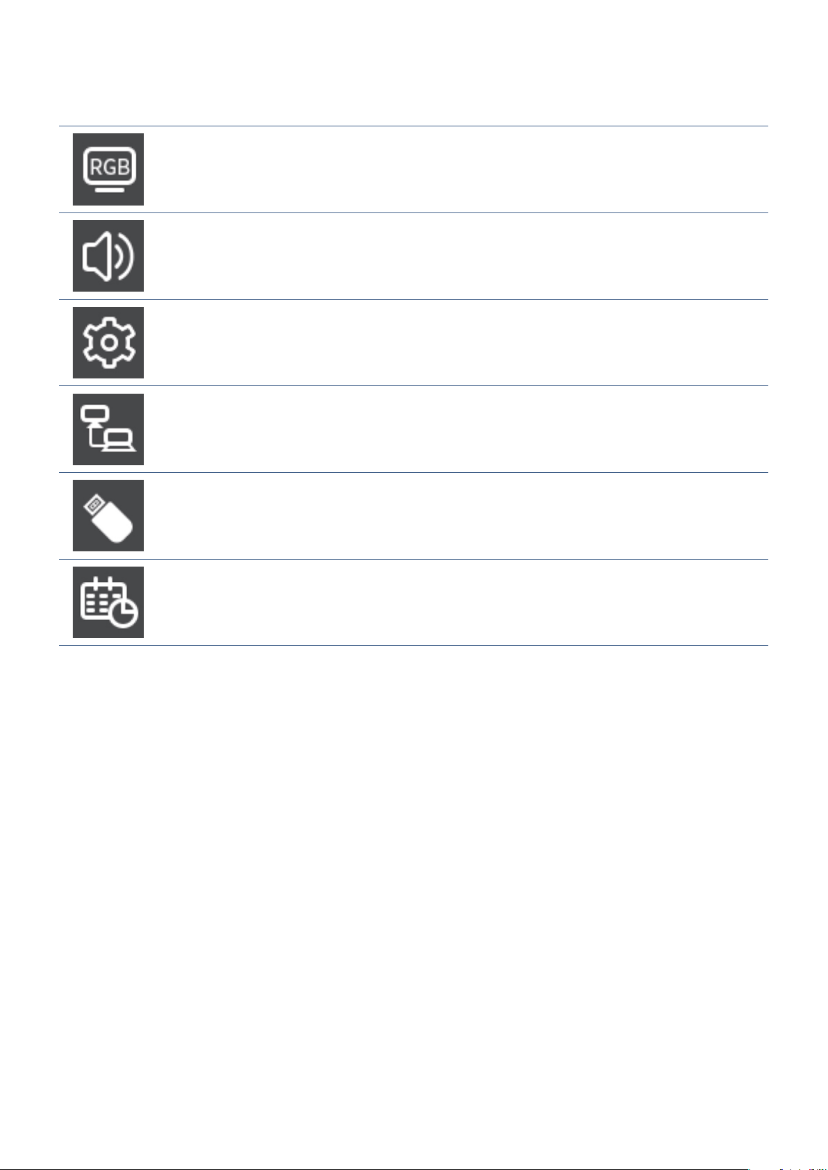
Video settings:
Select one of the default picture modes, manually adjust the color settings, adjust the aspect
ratio, and adjust the other settings related to the image.
Audio settings:
Adjust the volume, balance, equalizer, and the other settings related to the audio.
Setup settings:
Display the monitor information, select the language, or return the settings to their default
values.
Control settings:
Congure settings such as the network information.
Media Player settings:
Congure the USB Demo Mode and other settings.
Schedule settings:
Create auto power on/off schedules for the monitor and set the sleep timer.
37
The Media Player plays image, video, and music les
located on a USB storage device connected to the USB
Type-A port of the monitor (page 19).
To open the Media Player menu, press the INPUT button of
the remote control and select [Media Player].
NOTE: Connect the USB storage device where the
les are stored to the USB Type-A port of the
monitor.
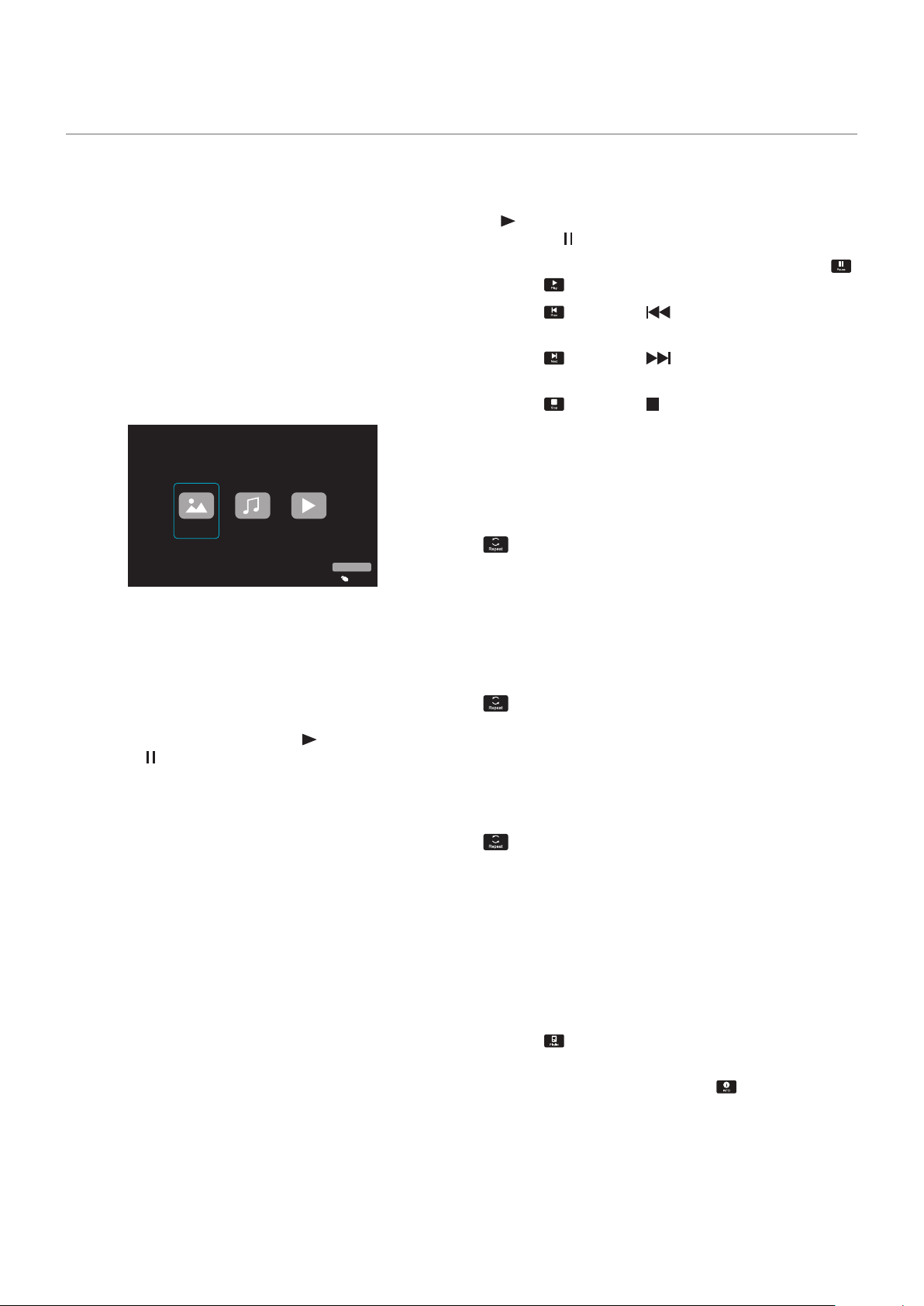
Media Player Menu
This function can be used to display photos (still images)
and play video and music les stored in the USB storage
device.
Photo
Music Movie
USB
Input Select
Select the type of the le you want to play between [Photo],
[Music], and [Movie].
Selecting Files to Play
• Playing a le
Select a le using the
p
,
q
,
t
, and
u
buttons of the
remote control, and then press the
(Play) button.
Press the
button to pause the playback.
• Playing multiple les
1. Select les using the
p
,
q
,
t
, and
u
buttons of the
remote control.
2. Press the ENTER button of the remote control to add
a checkmark next to each le.
3. This saves the les as a playlist in the USB storage
device.
NOTE: • The selected les play in the order they are
displayed in the folder.
• File names must contain only alphanumeric
characters.
Operation buttons
• Press the ENTER button of the remote control while playing
a le to display the OSD operation menu on the screen.
• Press the
t
,
u
buttons to highlight an item in the operation
menu and then press the ENTER button to select it.
• Press the
q
button of the remote control to close the
operation menu.
Slideshow Operation
• Select les using the
p
,
q
,
t
,
u
buttons and press the
(Play) button to start a slideshow.
Press the
button to pause the slideshow.
• To pause the slideshow using the OSD menu, select
.
Select
to resume the slideshow.
• Select
or press the button of the remote control
to return to the previous image.
• Select
or press the button of the remote control
to go to the next image.
• Select
or press the button of the remote control to
stop the slideshow.
Repeat play
Repeat setting can be congured for le playback. The
following modes can be selected.
N
- Repeat off
• No selected les.
- All les in the folder are played once, in the sorted
order.
• One or more selected les.
- Any les you checked are played once, in the sorted
order.
1
- Repeat one le
• - A le is playing: the current le plays on a loop. - No
le is playing: the highlighted le in the folder plays on a
loop.
• One or more selected les.
The rst checked le in the sorted order plays on a loop.
A
- Repeat all les
• No selected les.
- All les in the folder are played on a loop, in the sorted
order.
• One or more selected les.
- The selected les are played on a loop, in the sorted
order.
Other functions
• Select to view the playlist of les.
You can also select the les to play from the list.
• While a le is being played, select
to show
information on the le being displayed.
Using the Media Player Menu

38
Video and Music Operations
• Select les using the
p
,
q
,
t
,
u
buttons of the remote
control and press the
(Play) button to start playback.
Press the
button to pause the playback.
• To pause the playback using the OSD menu, select
.
Select
to resume the playback.
• Select
to start fast forward.
FF2X
,
FF4X
,
FF8X
,
FF16X
,
FF32X
(The sound is not output.)
(FF32X can be selected only when a video le is played.)
• Select
to start fast backward.
FB2X
,
FB4X
,
FB8X
,
FB16X
,
FB32X
(The sound is not output.)
(FB32X can be selected only when a video le is played.)
• Select
or press the button of the remote control
to return to the previous le.
• Select
or press the button of the remote control
to return to go to the next le.
• Select
or press the button of the remote control to
stop the playback.
Repeat play
Repeat setting can be congured for le playback. The
following modes can be selected.
N
- Repeat off
• No selected les.
- All les in the folder are played once, in the sorted
order.
• One or more selected les.
- Any les you checked are played once, in the sorted
order.
1
- Repeat one le
• - A le is playing: the current le plays on a loop. - No
le is playing: the highlighted le in the folder plays on a
loop.
• One or more selected les.
The rst checked le in the sorted order plays on a loop.
A
- Repeat all les
• No selected les.
- All les in the folder are played on a loop, in the sorted
order.
• One or more selected les.
- The selected les are played on a loop, in the sorted
order.
Other functions
• Select to view the playlist of les.
You can also select the les to play from the list.
• While a le is being played, select
to show
information on the le being played.
NOTE: • Only use USB mass storage class devices.
• We cannot guarantee to support all
commercially-available USB mass storage
devices.
• Do not use a USB hub.
• Do not use a multi-partition USB storage
device.
• The USB Type-A port of the monitor
supports 5 V / 500 mA. When using a
USB device of more than 500 mA, we
recommend using the AC adapter supplied
with the USB device.
• When connecting a USB device formatted
as FAT16 or FAT32 to a computer, a
message prompting you to scan and x
the USB device may appear. If that occurs,
execute “Scan and x”.
39
Data Format for USB
Supported le system
FAT16 (max 2 GB),
FAT32 (max 4 GB)
Max folder level
9
Max number of photos
997
Photo mode
File extension Data format Min resolution (H x V) of
image
Max resolution (H x V) of
image
JPEG, JPG, JPE Baseline JPEG 75 x 75 pixels 15,360 x 8,640 pixels
Music mode
File extension Data format Max bit rate Max channel No.
MP3 MPEG1/2 Layer3 (MP3) 320 kbps 2 ch
Movie mode
Container format Supported video codec Supported audio codec
MPG, MPEG MPEG1, MPEG2, MPEG4 LPCM, MP3, AAC
TS MPEG2, H.264, HEVC/H.265 LPCM, MP3, AAC
MP4 MPEG2, MPEG4, H.263, H.264, HEVC/H.265 LPCM, MP3, AAC
WMV H.264, Windows Media Video 9 WMA 9, WMA 10 Pro
Video codec Max bit rate of video*
2
Max resolution (H x V) of
video
MPEG1 40 Mbps 1920 x 1080 @30 Hz
MPEG2 40 Mbps 1920 x 1080 @30 Hz
MPEG4 40 Mbps 1920 x 1080 @30 Hz
H.263 40 Mbps 1920 x 1080 @30 Hz
H.264 135 Mbps 3840 x 2160 @60 Hz
HEVC/H.265 100 Mbps 3840 x 2160 @60 Hz
Windows Media Video 9
(WMV3)
40 Mbps 1920 x 1080 @30 Hz
Audio codec Max bit rate of audio*
2
Max channel No.
LPCM 1.5 Mbps 5.1 ch*
1
MPEG1/2 Layer3 (MP3) 320 kbps 2 ch
AAC AAC-LC: 576 kbps
HE-AAC v1: 288 kbps
HE-AAC v2: 144 kbps
5.1 ch*
1
WMA 9 Standard 320 kbps 2 ch
WMA 10 Pro M0 192 kbps 2 ch
WMA 10 Pro M1 384 kbps 5.1 ch*
1
WMA 10 Pro M2 768 kbps 5.1 ch*
1
*1: It is played with down-converted to 2 ch.
*2: It may not play smoothly with a combination of max bit rate of video and audio.
NOTE: • Sometimes, it may not be possible to play a video le even when the conditions above are met.
The le may not be played properly depending on the bit rate.
Video les made with a codec not supported by the monitor cannot be played.
• Supported color format is YUV only. RGB and CMYK color format les can not be played correctly.
• When playing a slideshow, please use YUV 4: 2: 0 image format les.

40
Chapter 5 Advanced Operation
This Chapter Includes:
>
"Creating a Power Schedule" on page 41
>
"Using Picture Modes" on page 42
>
"Setting Security and Locking the Monitor Controls" on page 43
>
"Locking the Button Controls" on page 44
41
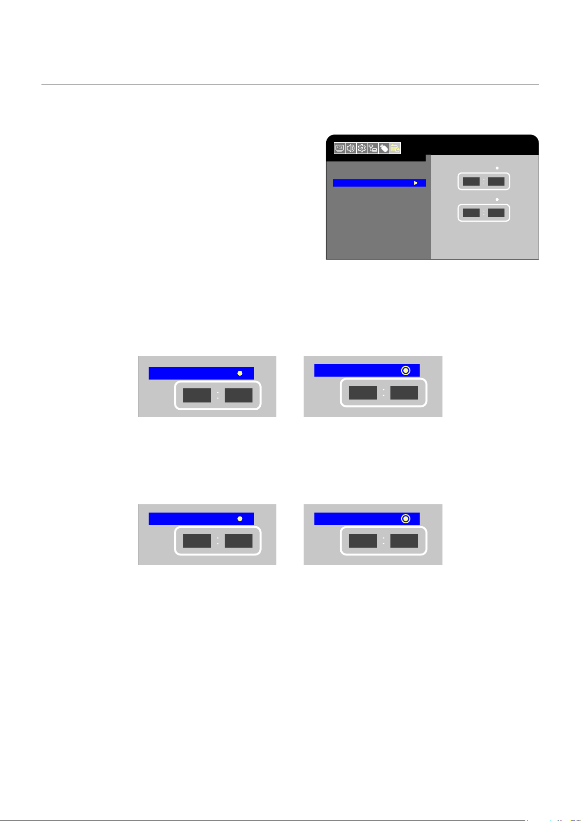
Creating a Power Schedule
The schedule function allows the monitor to automatically switch between power on and standby mode at different times.
To program the schedule:
1. Enter the [SCHEDULE] menu in the OSD menu.
a. Use the
p
/
q
buttons of the remote control to select [Current
Time settings].
b Press the ENTER button of the remote control. Press the
t
,
u
buttons of the remote control to move between the hours and
minutes elds.
c Use the
p
/
q
buttons of the remote control to set the time.
2. After setting the time, press the MENU button of the remote
control.
3. Use the
p
/
q
buttons of the remote control to select [Schedule
settings].
a. Press the ENTER button of the remote control. Place the cursor on [Power On] and press the ENTER button of the
remote control to enable the [Power On]. Press the
t
,
u
buttons of the remote control to move between the hours and
minutes elds.
Use the
p
/
q
buttons of the remote control to set the time.
Schedule
Sleep Timer
Current Time settings
Schedule settings
Power On
Power Off
Move Adjust
HDMI1
Return
MENU
EXIT
EXIT
12
00
12
00
Sleep Timer
Current Time settings
Schedule settings
Move Adjust
Power On
Power Off
Schedule
HDMI1
Return
MENU
EXIT
EXIT
12
00
12
00
Power On disabled Power On enabled
b Use the
t
,
u
buttons of the remote control to place the cursor on [Power Off] and then press the ENTER button of the
remote control to enable [Power Off]. Press the
t
,
u
buttons of the remote control to move between the hours and
minutes elds.
Use the
p
/
q
buttons of the remote control to set the time.
Sleep Timer
Current Time settings
Schedule settings
Move Adjust
Schedule
Power On
Power Off
HDMI1
Return
MENU
EXIT
EXIT
12
00
12
00
Sleep Timer
Current Time settings
Schedule settings
Move Adjust
Power On
Power Off
Schedule
HDMI1
Return
MENU
EXIT
EXIT
12
00
12
00
Power Off disabled Power Off enabled
4. After setting the schedule, press the MENU button or RETURN button to return to the previous OSD menu.
HDMI1
Schedule
Sleep Timer
Current Time settings
Schedule settings
Power On
Power Off
12
00
12
00
42
Using Picture Modes
There are different picture modes available. They have been congured for different applications as described in the “Picture
Mode Types” table below.
To change picture modes:
In the OSD menu, go the [Video] -> [Picture Mode], or press the MODE button of the remote control to select a mode.
HDR Video -> Dynamic -> Standard -> Conferencing -> HighBright -> Custom
Picture Mode Types
Picture Mode Purpose
HDR Video Setting for HDR format video (can be selected only when an HDR signal is input)
Dynamic High-contrast video setting
Standard Standard video setting
Conferencing Video setting suited for video conferences
HighBright Video setting suited for brighter environments
Custom Customizable settings

43
Setting Security and Locking the Monitor Controls
Under normal operation, the monitor can be controlled by any person using the remote control or the monitor control panel. You
can prevent unauthorized use and changes to the monitor settings by enabling the security and lock settings.
The security and locking functions covered in this section are:
• Locking the monitor control panel buttons
• Locking the remote control buttons
44
Locking the Button Controls
The lock settings prevent the monitor from responding to button presses on the remote control or monitor control panel. When
locking the button controls, some buttons can be congured to remain unlocked.
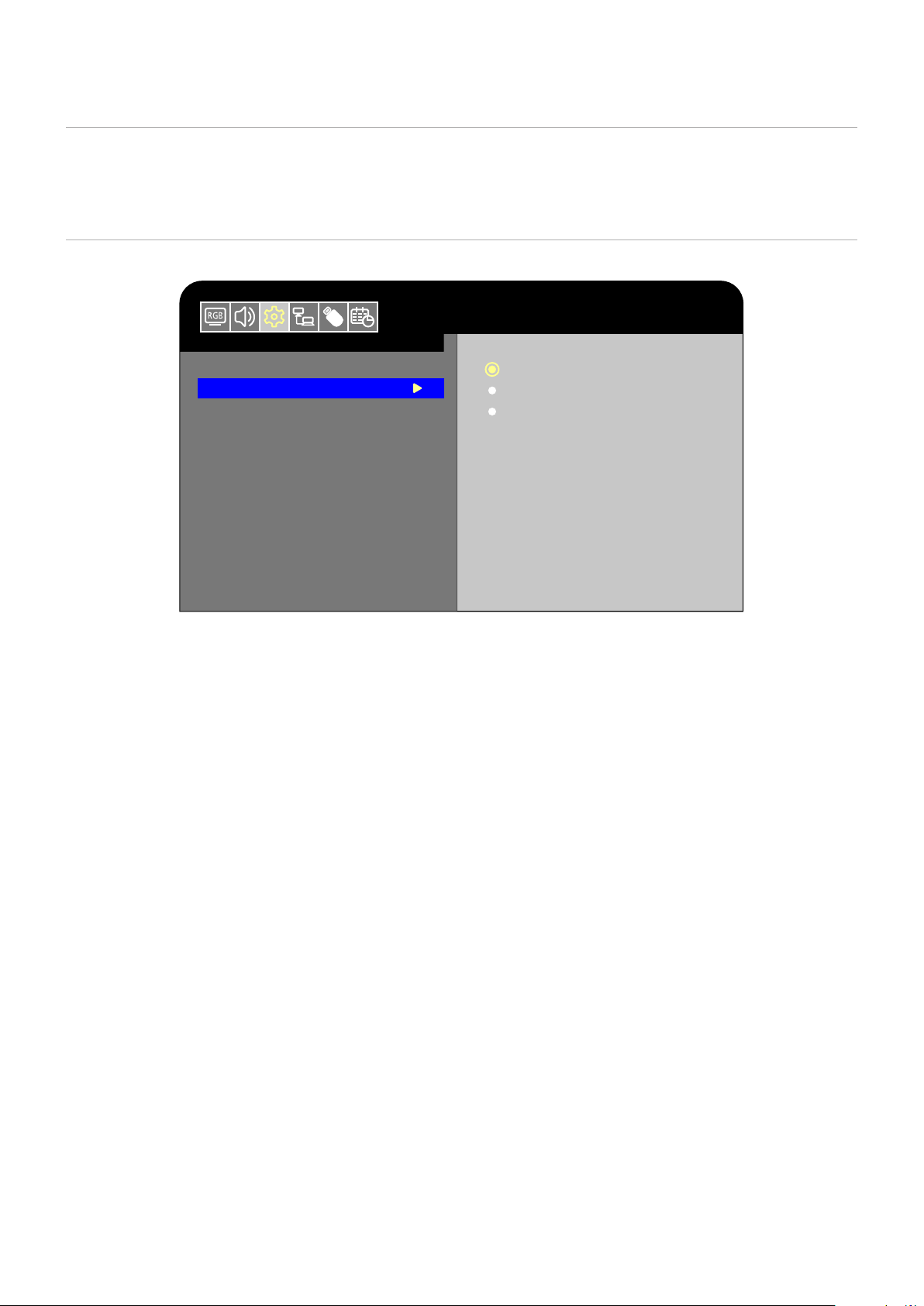
Locking the Control Panel Buttons
The [Key Lock Settings] prevent the monitor from being controlled using the buttons on the monitor control panel.
Setup
Input Labels
Key Lock Settings
IR Lock Settings
LED Indicator
Mute Settings
ROTATE 180°
Thermal Management
Signal Information
Off
Mode 1
Mode 2
HDMI1
1. In the OSD menu, go to [Setup] -> [Other settings] and select [Key Lock Settings].
2. Select the key lock range.
• Off: All buttons operate normally.
• Mode1: Only the power button and the Input mode switching function operate.
• Mode2: All buttons are locked. (Only the power button can be used during standby mode.)
NOTE: The buttons are locked 3 seconds after Mode1 or Mode2 has been selected.
Unlocking the Monitor Panel Button Controls
Carry out the following with the monitor in On mode.
•
OSD menu:
To remove the lock and restore normal button operation, set the [Key Lock Settings] to [Off] using the remote
control.
•
Monitor buttons:
To remove the lock and restore normal button operation, hold the MENU button pressed for 5 seconds or
more.
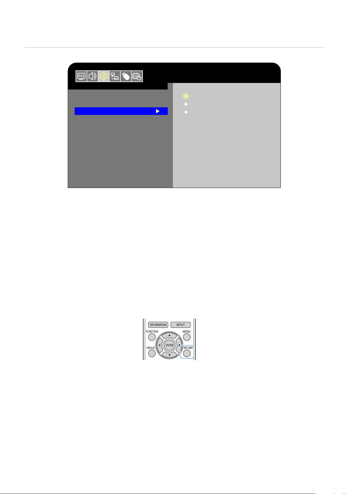
45
Locking the Remote Control Buttons
The [IR Lock Settings] prevent the monitor from being controlled using the remote control.
Setup
HDMI1
Input Labels
Key Lock Settings
IR Lock Settings
LED Indicator
Mute Settings
ROTATE 180°
Thermal Management
Signal Information
Off
Mode 1
Mode 2
1. In the OSD menu, go to [Setup] -> [Other settings] and select [IR Lock Settings].
2. Select the key lock range.
• Off: All buttons operate normally.
• Mode1: Only the POWER and the INPUT buttons operate.
• Mode2: All buttons are locked. (Only the POWER button can be used during standby mode.)
NOTE: The buttons are locked 3 seconds after Mode1 or Mode2 has been selected.
Unlocking the Remote Controls
Carry out the following with the monitor in On mode.
•
OSD menu:
To remove the lock and restore normal button operation, set the [IR Lock Settings] to [Off] using the monitor
buttons.
•
Remote control:
To remove the lock and restore normal button operation, hold the RETURN button pressed for 5 seconds
or more.

46
Chapter 6 External Control
This Chapter Includes:
>
"Controlling the Monitor via RS-232C" on page 47
>
"Controlling the Monitor via LAN" on page 48
>
"HTTP Browser" on page 50
>
"Commands" on page 52
Connecting an external device
There are two options to connect an external device to control the monitor.
• Connection via RS-232C
Connecting an external device with the RS-232 cable of the monitor.
• Network (LAN) Interface
Connecting a network to the LAN port of the monitor with a LAN cable.
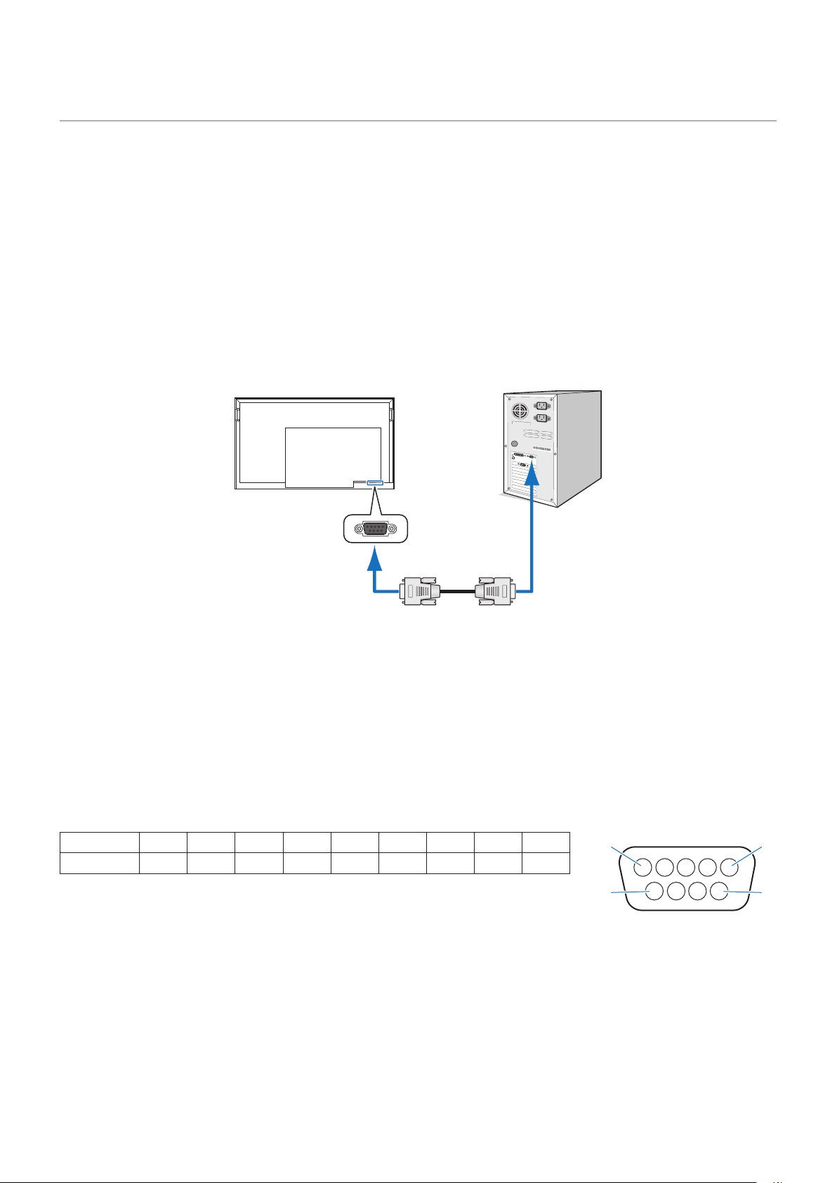
47
Controlling the Monitor via RS-232C
This monitor can be controlled by connecting a personal computer with an RS-232C terminal to the RS-232C terminal of the
monitor with a commercially-available RS-232C crossover cable.
NOTE: Set [Control Interface] under [Control Settings] to [RS-232C] (page 74).
Connection
Monitor + computer.
• Turn off the monitor and the computer before connecting a computer to the monitor.
• First, turn the computer on, and then turn the monitor on.
• To control the monitor via commands sent from a computer connected with an RS-232C cable, use the control commands.
Instructions for the control commands can be found in “Commands” in “External Control” in this manual.
RS-232C Cable
Computer
RS-232C
NOTE: • If your computer is equipped only with a 25-pin serial port connector, a 25-pin serial port adapter is required.
• Contact your supplier for details.
• For the pin assignment, see “Pin Assignment RS-232C input/output”.
This monitor uses RXD, TXD and GND lines for RS-232C control.
A commercially-available crossover cable (not included) should be used for RS-232C control.
Pin Assignment
RS-232C input / output
Pin No 1 2 3 4 5 6 7 8 9
Name NC RXD TXD NC GND NC NC NC NC
This monitor uses RXD, TXD and GND lines for RS-232C control.
D-sub 9-pin (monitor side)
1
6
5
9
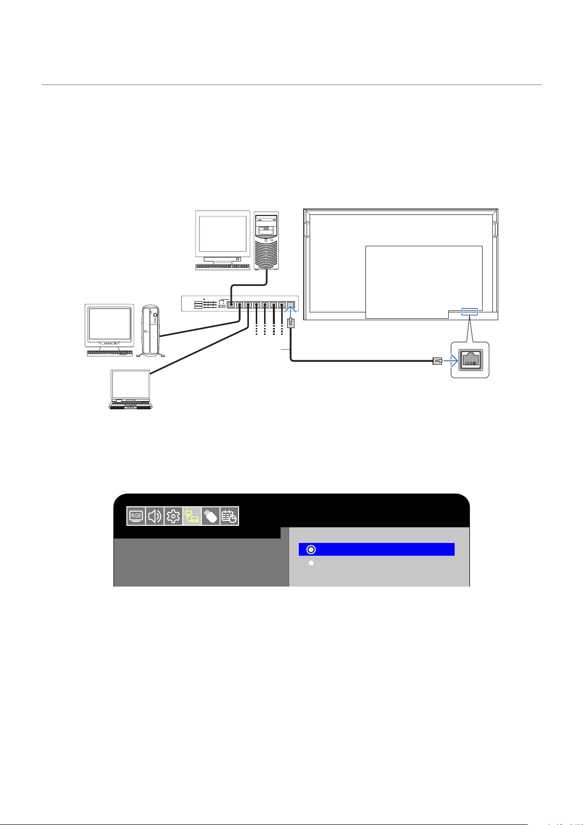
48
Controlling the Monitor via LAN
Connect the monitor to the network
The monitor is equipped with a LAN port (RJ-45). Connecting the monitor to a network allows you to control the monitor from a
computer via a network. To use a LAN connection, you are required to assign an IP address to the monitor (page 74).
The monitor will obtain an IP address automatically when connected to a DHCP network.
Example of LAN connection
Server
Hub
Use a category 5 or higher LAN cable.
LAN cable
(commercially available)
To enable command control via LAN on the monitor, check the settings on both the [Control Interface] in the OSD menu and
TCP settingsin the web browser.
Change the control interface to LAN with MENU
Set [Control Interface] under [Control Settings] to [LAN] (page 74).
HDMI1
Control Settings
Control Interface
Network Settings
Reset Network Settings
LAN
RS-232C
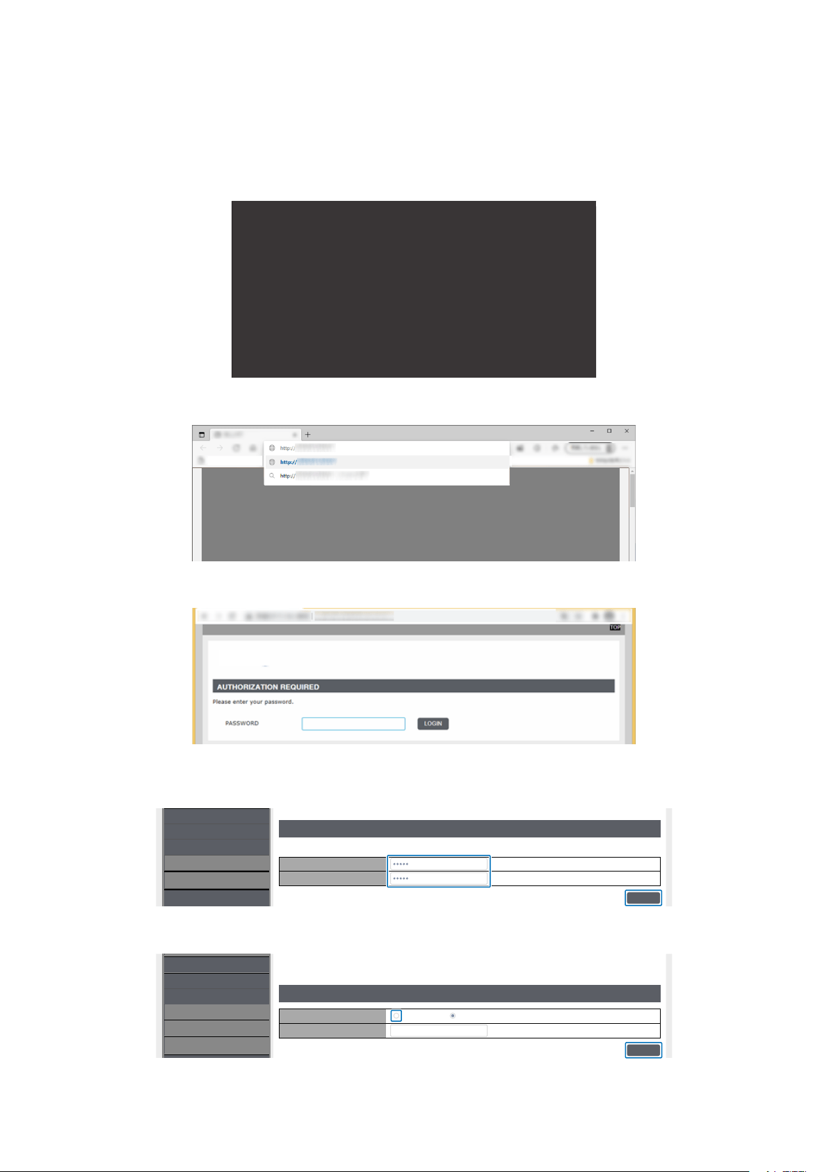
49
Enable TCP connection in a web browser
Command access is disabled by default. Access the display in a web browser and select Enabled in TCP.
1. Check the IP address of the monitor.
Press the INFORMATION button twice and check the IP address on INFORMATION 2.
INFORMATION2
RS-232C/LAN
DHCPCLIENT
IPアドレス:
サブネットマスク:
デフォルトゲ ートウェイ:
優先DNS:
代替DNS:
MACアドレス
LAN
オン
XX:XX:XX:XX:XX:XX
169.254.150.43
255.255.0.0
0.0.0.0
0.0.0.0
0.0.0.0
2. Launch the web browser on your computer and access the display.
URL: http://<Address IP of the monitor>
3. Log in.
Initial password: admin
4. Change password (rst access)
For the rst access, you will be asked to change your password.
Enter the password in [PASSWORD] and [CONFIRMATION] and click [SAVE].
PASSWORD SETTINGS
PASSWORD
Changes the administrator password for accessing the device
CONFIRMATION
NETWORK
SYSTEM
LOGOUT
TCP
SAVE
NAME
5. Enable TCP.
Check ENABLE and click [SAVE]. Do not change the PORT number to anything other than 10008.
PROTOCOL
TCP SETTINGS
TCP
CONFIRMATION
NETWORK
SYSTEM
LOGOUT
TCP
SAVE
NAME
10008
ENABLE
DISABLE

50
HTTP Browser
Overview
Connect the monitor with a commercially-available LAN cable to congure the LAN settings using the HTTP server function.
This monitor uses “JavaScript” and “Cookies” and the browser should be set to accept these functions. Refer to the help les for
the Web browser to change the settings to use JavaScript and Cookies.
To access the HTTP server, launch a web browser on a computer connected to the same network as the monitor and enter the
following URL in the Web address eld.
Network Settings
http://<Address IP of the monitor>
Ex) When the IP address of the monitor is "192.168.73.1"
To access the network settings, specify http://192.168.73.1/index.html
in the address or URL input eld.
NOTE: • By default, the IP address of the monitor is set automatically. After a reset, the IP address is obtained
automatically.
• Depending on the network environment, the display speed and response to commands or clicks on buttons may
be slow, or the operations may not be recognized. In such a case, consult your network administrator.
The monitor may not respond if the buttons shown on the browser are repeatedly pressed in rapid intervals. In
such a case, wait a moment and try again. If you still can’t get a response, turn the monitor off and then back on.
• If the monitor Network Settings screen does not appear in the Web browser, press the Ctrl+F5 keys to refresh
your Web browser. If the screen does not appear, clear the cache of the Web browser.
Preparation Before Use
Connect the monitor to the network using a commercially-available LAN cable before attempting to use browser operations.
Set [Control Interface] under [Control Settings] to [LAN] (page 74). Operation with a browser that uses a proxy server may not
be possible depending on the type of proxy server and the setting method. Although the type of the proxy server will be a factor,
it is possible that items that have been set will not be shown depending on the effectiveness of the cache, and the settings
congured from the browser may not be reected in operation. It is recommended that a proxy server is not used unless the
network environment requires it.
Access by Web browser
Access the following address to show HOME. Click the links on the left-hand column on the HOME screen to access the setting
screens.
http://<Address IP of the monitor>
The default login password is “admin”.
After logging in, the password change screen will be displayed. When you change the password, the setting menu will be
displayed.
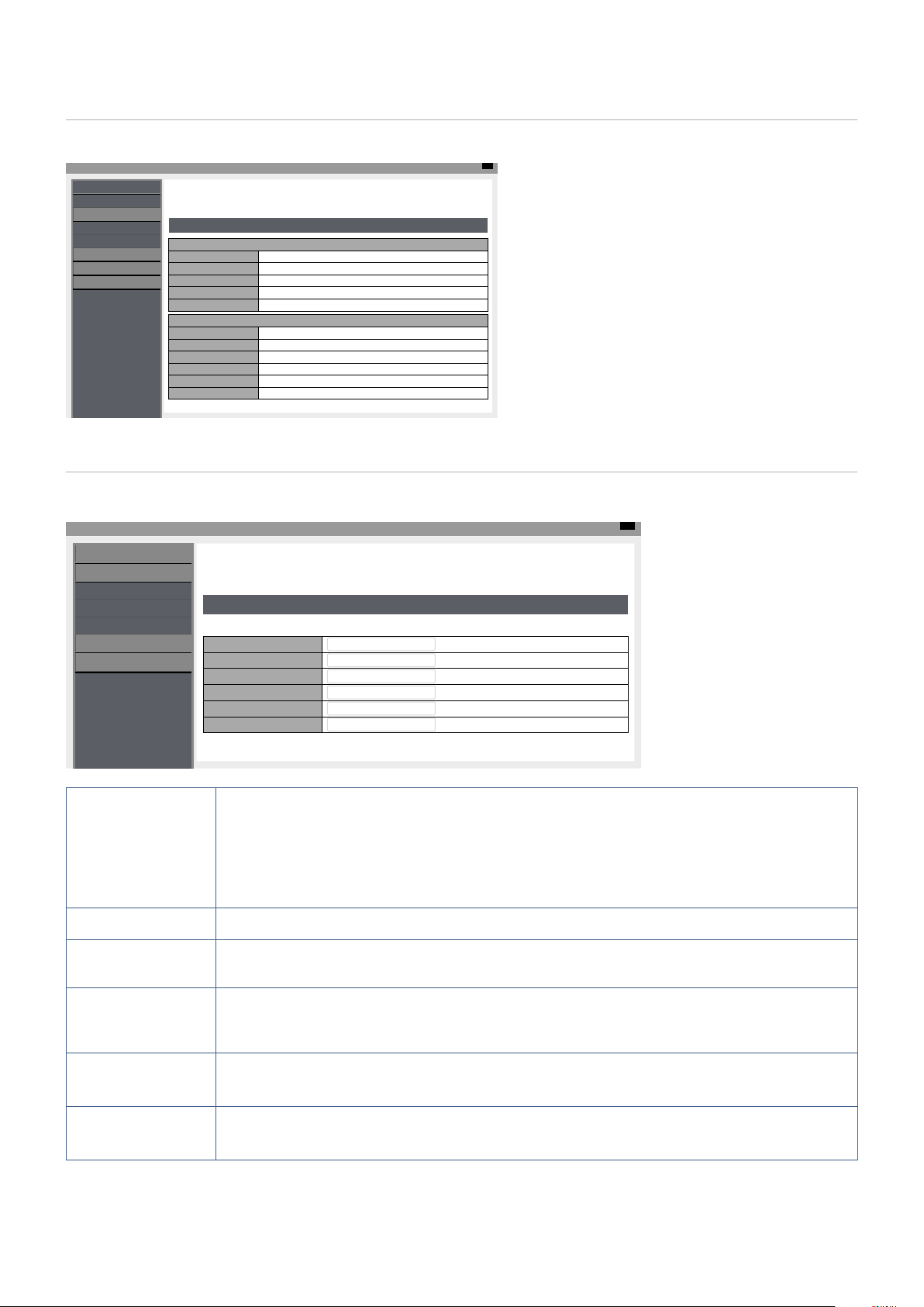
51
OSD Menu Settings in the Monitor Web Controls
The functions related to the network can be congured the same way as in the OSD menu using the links below.
Top
INPUT SOURCE: HDMI1
STATUS
PROTOCOL
STATUS
SYSTEM
MODEL NAME XXXXX
SERIAL XXXXXXXXXX
FIRMWARE VERSION Vx.x.x / Vx.x.x
LOCAL TIME WWW MMM DD XX:XX:XX 20YY
UPTIME XXh XXm XXs
NETWORK
IP ADDRESS 192.168.0.10
SUBNET MASK 255.255.255.0
DEFAULT GATEWAY 0.0.0.0
DNS PRIMARY 0.0.0.0
DNS SECONDARY 0.0.0.0
MAC Address XX:XX:XX:XX:XX:XX
NETWORK
SYSTEM
LOGOUT
TCP
NAME
OVERVIEW
Network Settings
Click on “NETWORK” on the left-hand column on the HOME screen to enter the setting screen.
Top
INPUT SOURCE: HDMI1
STATUS
PROTOCOL
NETWORK SETTINGS
DHCP
INTERFACE
IP ADDRESS 192.168.0.10
Off
SUBNET MASK 255.255.255.0
DEFAULT GATEWAY 0.0.0.0
DNS PRIMARY 0.0.0.0
DNS SECONDARY 0.0.0.0
NETWORK
SYSTEM
LOGOUT
TCP
NAME
DHCP Select a method for setting the IP ADDRESS.
Off: Sets xed network settings.
On: Obtains the network settings from the DHCP server on the network.
Manual DNS: Obtains the network settings from the DHCP server on the network but the DNS
is set manually.
NOTE: Consult your network administrator if you have any trouble with the connection.
IP ADDRESS Set the IP address for the monitor connected to the network when [Off] is selected for [DHCP].
SUBNET MASK Set the subnet mask for the network to which the monitor is connected when [Off] is selected for
[DHCP].
DEFAULT GATEWAY Set the default gateway for the network to which the monitor is connected when [Off] is selected for
[DHCP].
Enter [0.0.0.0] to delete the setting.
DNS PRIMARY Enter the IP address of the primary DNS server of the network connected to the monitor.
NOTE: Enter [0.0.0.0] to delete the setting.
DNS SECONDARY Enter the IP address of the secondary DNS server of the network connected to the monitor.
NOTE: Enter [0.0.0.0] to delete the setting.
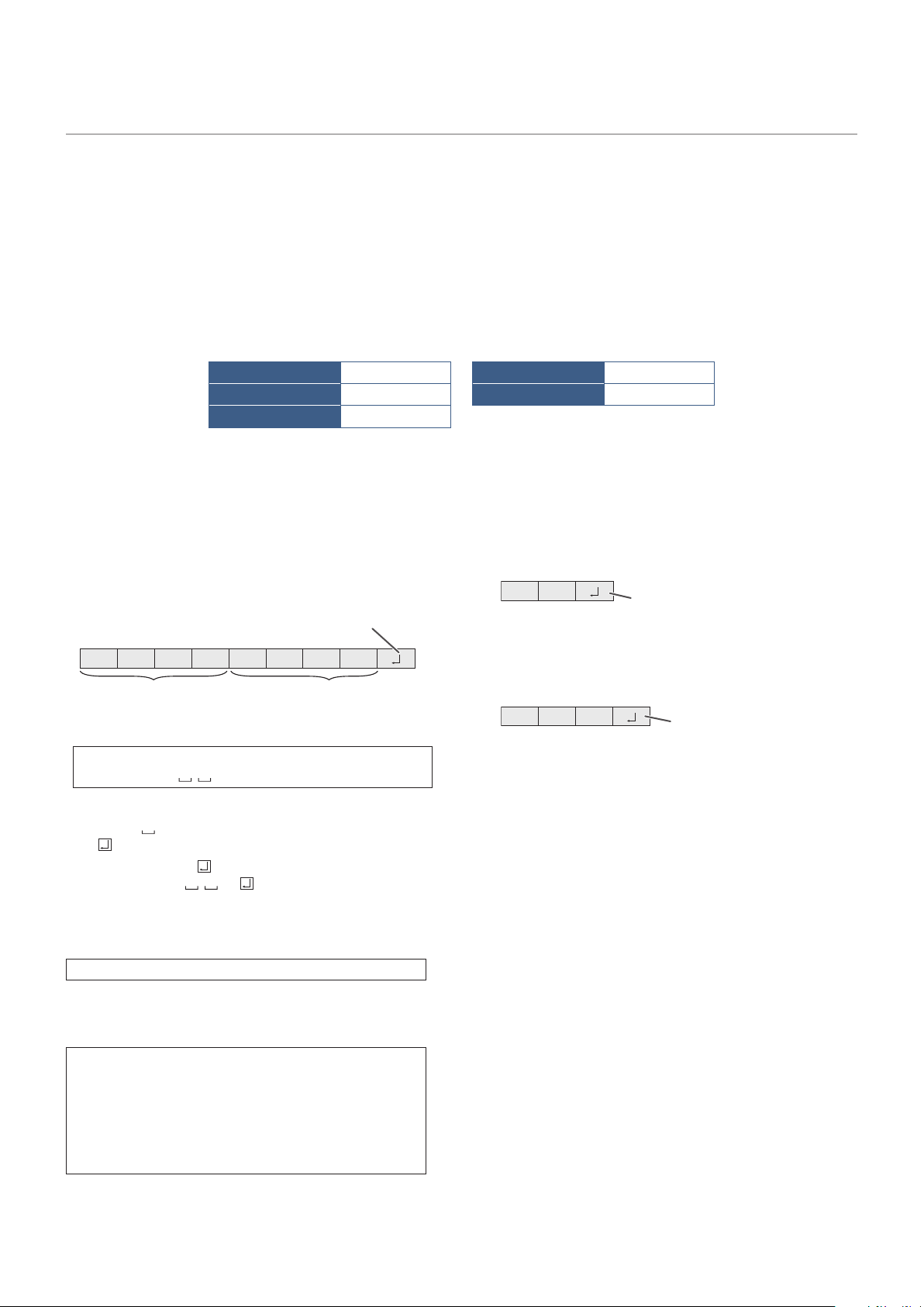
52
Commands
Connecting the monitor to a computer via RS-232C or to a network via LAN allows for the transmission of commands to the
monitor, providing remote control of the monitor from a connected device. For the commands, refer to "RS-232C Command List"
on page 82 of this manual.
Controlling the Monitor with a computer (RS-232C)
You can control this monitor from a computer via RS-232C (COM port) on the computer.
Communication conditions
Set the RS-232C communication settings on the computer to match the monitor’s communication settings as follows:
BAUD RATE 9600 [bps] STOP BIT 1 [bit]
DATA LENGTH 8 [bits] FLOW CONTROL NONE
PARITY NONE
Communication procedure
Command format
When a command is sent from the computer to the monitor,
the monitor operates according to the received command
and sends a response message to the computer.
C1 C2 C3 C4 P1 P2 P3 P4
Return code
Command field
(4 prescribed
alphanumerical characters)
Parameter field
(4 character string comprised of:
0-9, +, -, space, ?)
Example: VOLM0030
VOLM
30
* Be sure to input 4 characters for the parameter. Pad with
spaces (“ ”) if necessary.
(“
” is a return code (0D
H
, 0A
H
or 0D
H
))
Wrong : VOLM30
Right : VOLM 30
When the parameter part is 5 or more characters, specify
parameters using a specied number of characters without
using spaces.
Example: PASS012345
If a command has “R” listed for “Direction” in the
“RS-232C command table” on page 54, the current value
can be returned by using “?” as the parameter.
Example:
VOLM ? ? ? ?
←
From computer to monitor
(How much is current volume
setting?).
30
←
From monitor to computer
(Current volume setting: 30).
Response code format
When a command has been executed correctly
O K
Return code
(0DH, 0AH)
A response is returned after a command is executed.
When a command has not been executed
R R E
Return code
(0D
H
, 0A
H
)
NOTE: • “ERR” is returned when there is no relevant
command or when the command cannot be
used in the current state of the monitor.
• If communication has not been established
for reasons such as a bad connection
between the computer and monitor, nothing
is returned (not even ERR).
• “ERR” may be returned when a command
cannot be received correctly due to
interference from the surrounding
environment.
Please ensure that the system or software
resends the command if this occurs.
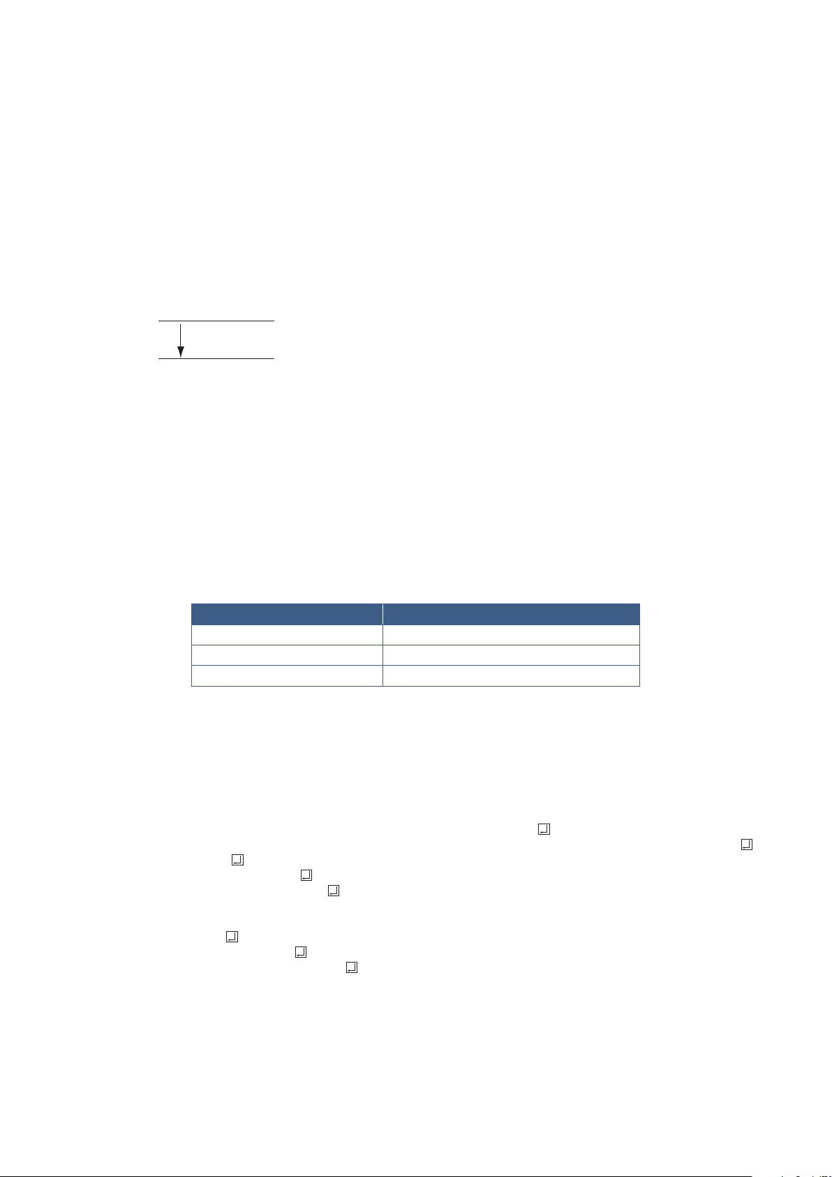
53
Communication interval
• The transmission time interval of command should be
within 100 ms.
• After “OK” or “ERR” is returned, you must send the
following commands.
To set a timeout for the command response, specify 10
seconds or longer.
• Provide an interval of 100 ms or more between the
command response and the transmission of the next
command.
VOLM0020
OK
INPS0001
WAIT
OK
Interval of 100 ms or more
NOTE: • Before sending a power “On” or “Off”
command, it is recommended that you
perform buffer clear at the sending
application side.
• If you send the following command, wait
a specied interval after receiving the
command response, and then send the next
command.
- All reset command: :Approx. 30 seconds
- Power “On” or “Off” command: Approx. 15
seconds
- Input mode selection command: Approx.
10 seconds
(1) Connect the computer to the monitor.
1. Specify the IP address and port number and connect
the computer to the monitor.
When connection has been established successfully,
[Login] is returned as response.
2. Send the user name.(see page 79)
• Send [user name] + [
].
• If the user name is not set, send [
].
• When the transmission is successful, [
Password] is returned as response.
3. Send the password.(see page 79)
• Send [password] + [
].
• If the password is not set, send [
].
• When the transmission is successful, [OK
] is
returned as response.
(2) Send commands to control the monitor.
• The commands used are the same as those for
RS-232C. Refer to the communication procedure
(see page 52) for operation.
• Usable commands are provided in the RS-232C
command table (see page 78).
(3) Disconnect the connection with the monitor
and quit the function.
1. Send [BYE ].
When the transmission is successful, [Goodbye
] is
returned and the connection is disconnected.
NOTE: If there is no signal for approx. 5 minutes, the
connection is disconnected.
Controlling the Monitor with a computer (LAN)
You can control the monitor using RS-232C commands (see page 78) via terminal software and other
appropriate applications.
Set the TCP connection to enable in a web browser. (see page 49)
Read the manual for the terminal software for detailed instructions.
Communication conditions
Set the LAN communication settings on the computer to match the monitor’s communication settings as follows:
Item Details
PROTOCOL TCP
PORT NUMBER 10008 (Cannot be changed)
COMMUNICATION SPEED AUTO setting (10/100Mbps)

54
Chapter 7 Troubleshooting
This Chapter Includes:
>
"When a problem occurs with the monitor" on page 55
>
"Nothing is displayed" on page 55
>
"The image is not displayed correctly" on page 56
>
"An instruction or caution screen is displayed" on page 57
>
"Others (when connected to a computer)" on page 57
>
"Others (remote control, speakers)" on page 57
>
"Others (when connected via RS-232C or LAN)" on page 58
>
"When using a media player" on page 58
>
"When using a video device" on page 58
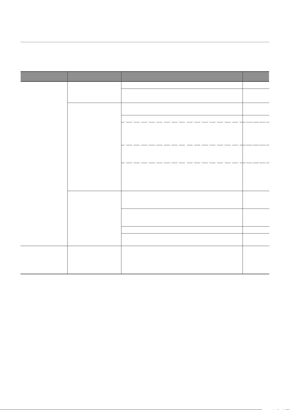
55
When a problem occurs with the monitor
In such a case, refer to the following.
Nothing is displayed
Symptom Condition Cause and solution Reference
Nothing is displayed
on the screen.
The power indicator is off
In the OSD menu, [Setup]
-> [Other Settings] -> [LED
Indicator] is set to [On]
Check that the power cord is properly connected. P. 8
Use another device to check that power is correctly supplied
to the outlet.
The power indicator is lit
green
A terminal to which no signal is input may be selected. Press
the input switch button to select a different input terminal.
P. 18
Display the OSD menu and check the following settings. P. 35
● If the OSD menu does not appear, the monitor may
malfunction.
Please contact an authorized SHARP servicing dealer or
service center for assistance.
● If the OSD menu is displayed properly, the monitor is
not malfunctioning. Adjust [Backlight / Brightness] and
[Contrast] in the [Video] settings.
P. 70
● If the image is not displayed after adjusting [Backlight /
Brightness] and [Contrast] in the OSD menu, check that
the connected device operates correctly. If the monitor is
connected to a computer, check the frequency, resolution,
and type of output signal on the computer.
P. 23
The power indicator is
ashing red
The power management function may be functioning. Press
any button on the keyboard, move the mouse, or press the
POWER button on the power cable or the remote control.
P. 20,
P. 30
Check that the signal cable is correctly connected to the
input and output terminals of the monitor and the connected
device.
P. 22
Check that the power adaptor is properly connected. P. 23
Check that the connected computer or video device is turned
on.
The image on the
screen disappeared.
The screen, on which
the image was correctly
displayed, turned black,
started to blink, or did not
display anything.*
The LCD panel needs to be replaced. Please contact an
authorized SHARP servicing dealer or service center for
assistance.
* If there is no input signal, the power LED ashes red.
* The lifespan of the backlight used in the monitor may end.
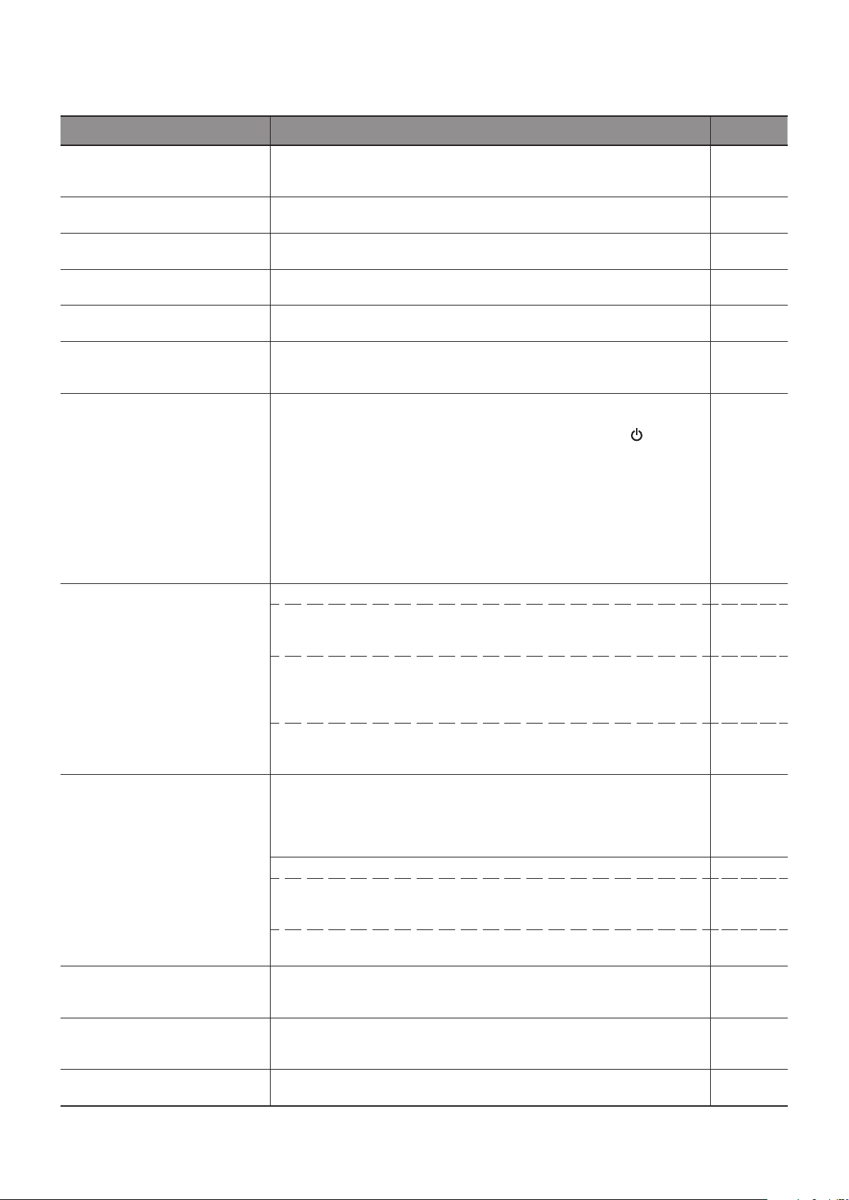
56
The image is not displayed correctly
Symptom Cause and solution Reference
Black dots (dots not lit) or bright
dots (dots always lit) appear on
the screen.
This is due to the characteristics of LCD panels and is not a malfunction.
The brightness of the image is
not even.
This may happen depending on the content displayed. This is due to the
characteristics of LCD panels and is not a malfunction.
The shadow of thin vertical lines
appears on the screen.
This may happen depending on the content displayed. This is due to the
characteristics of LCD panels and is not a malfunction.
Moiré appears when detailed
patterns are displayed.
This may happen when detailed patterns are displayed. This is due to the
characteristics of LCD panels and is not a malfunction.
The colors do not look correct
depending on the viewing angle.
The tint may greatly vary depending on the viewing angle (the angle from
which the screen is viewed).
P. 62-
65
The display condition of the
screen is changing gradually.
The display condition changes gradually while the monitor is being used. The
ambient temperature may also have an impact on the display condition.
This is due to the characteristics of LCD panels and is not a malfunction.
P. 20
After changing the screen, the
image of the previous screen
remains slightly.
When the same still image is displayed for a long time, this phenomenon of
persisting image may occur.
You may press the POWER button of the remote control or the of the
monitor to put the monitor on standby state, or display changing images
for about one day until the persisting image disappears naturally.
If the
still image is displayed for a really long time without putting the monitor on
standby mode or switching to the changing image, the persisting image may
not disappear. This is not a malfunction. It is recommended to switch input
mode to standby mode or turn the monitor off when not using it. If you are
concerned about persisting image, you can gradually eliminate persisting
image by reducing the setting value of "Image" -> "Contrast" in the OSD
menu. (Initial setting value: 50)
The colors are not displayed
correctly.
Display the OSD menu and check the following settings. P. 35
● If the OSD menu is not displayed properly, the monitor may malfunction.
Please contact an authorized SHARP servicing dealer or service center
for assistance.
● If the OSD menu is displayed properly, the monitor is not malfunctioning.
Select [Color] and adjust the colors as needed, or execute [Reset Video
Settings] under the [Video] settings to return the settings to their default
values.
P. 70
● If the OSD menu is displayed properly and the computer screen does not
appear correctly, check the connection to the computer as well as the
frequency, resolution and output signal type setting on the computer.
P. 22,
P. 60
The image is not displayed
correctly (problems not
mentioned above)
or the video is interrupted
momentarily.
The image quality may decrease or the video may be interrupted if a
transponder, a splitter, or a long cable is used. Replace the cable you
are using with a shielded cable, or connect directly to the monitor without
using a splitter. Noise may also appear on the screen or the video may be
interrupted depending on the usage environment and the cable used.
Display the OSD menu and check the following settings.
P. 35
● If the OSD menu is not displayed properly, the monitor may malfunction.
Please contact an authorized SHARP servicing dealer or service center
for assistance.
● If the video is interrupted when an HDMI signal with the 3840 x 2160 or
4096 x 2160 resolution is input, use an HDMI cable supporting 4K.
The power turns off
automatically.
Check the setting in [Setup] -> [Power save settings] -> [Auto Power Down].
Set the [CEC] setting under [Setup] -> [HDMI Settings] to [Off].
Check the setting in [Schedule] -> [Sleep Timer].
P. 72,
P. 76
The monitor does not operate
according to the schedule
function.
Check the setting in [Schedule] -> [Current Time settings].
Enable [Power On] under [Schedule] -> [Schedule settings].
Enable [Power Off] under [Schedule] -> [Schedule settings].
P. 76
The display is disturbed.
The display may be disturbed when power is turned on or when the settings
have been changed. This is not a malfunction.
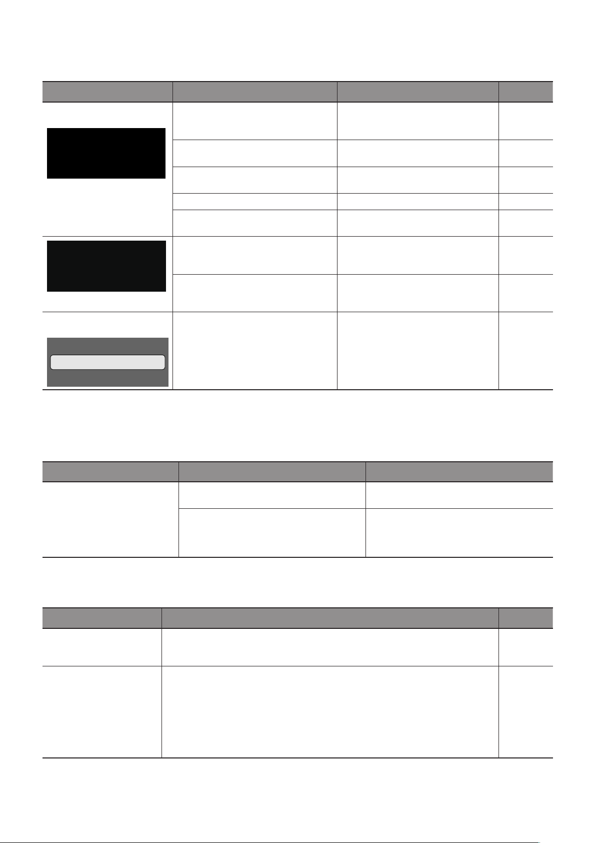
57
An instruction or caution screen is displayed
Symptom Cause Solution Reference
A caution message is
displayed on the screen.*
1
Attention !
No Signal
Please check input signal or Connection.
The signal cable may not be connected
properly to the input or output terminals
of the monitor or the computer.
Connect properly the signal cable to
the input and output terminals of the
monitor and the computer.
P. 22
The HDMI input may have switched. Set the [CEC] setting under [Setup] ->
[HDMI Settings] to [Off].
P. 72
The signal cable may be damaged. Check that the signal cable is not
damaged.
The computer may be turned off. Check that the computer is turned on.
The power management function of
the computer may be functioning.
Move the mouse or press a key on the
keyboard.
Out of Range
An improper signal may be input to the
monitor.
Change the frequency of the input
signal or the resolution of the
computer.
P. 60
A signal with a resolution higher than
the resolution supported by the monitor
may be input.
Change the frequency of the input
signal or the resolution of the
computer.
P. 60
A temperature warning is
displayed on the screen.
Warning!!
The internal temperature is high.
Please check the ambient temperature.
The ambient temperature exceeds the
operation guaranteed temperature.
Turn off the power of the monitor since
this problem may cause a malfunction.
P. 73
*1 Depending on the computer, a proper signal may not be output immediately after changing the resolution or the frequency and the caution
may be displayed for a while. In such a case, wait for a while. If the screen display returns to normal, it means the input signal is proper.
Others (when connected to a computer)
Symptom Cause Solution
I cannot change the
resolution or the number of
colors/The resolution or the
number of colors is xed.
Sometimes, the signal cannot be input and
output.
Restart the monitor and the computer.
The driver of the video card may not be
correctly recognized by the OS.
Reinstall the video card driver. For more
information on the reinstallation procedure,
refer to the computer manual or the support
service for the computer.
Others (remote control, speakers)
Symptom Cause and solution Reference
The remote control is not
functioning.
● The batteries may be at.
● Check that the batteries are inserted correctly (check the + and - sides).
● The [IR Lock Settings] may be set to [Mode 1] or [Mode 2].
P.
7
,
P.
73
The video is displayed
but there is no sound.
● Check that the audio cable is correctly connected. Check also that the audio
balance is not fully set to one side only. If the balance is set to one side only, set
it to the center.
● The sound may be muted. Press the MUTE button on the remote control and
check that the sound is output.
● The volume may be set to the minimum. Adjust the volume using the + and -
buttons on the main unit or the VOLUME button +/- (Volume adjustment) on the
remote control.
P.
19
,
P.
20
,
P.
71
58
Others (when connected via RS-232C or LAN)
Symptom Cause and solution Reference
Control via RS-232C is
not available.
Check that the RS-232C crossover cable is correctly connected. P.47
Control via LAN is not
available.
Check that the LAN cable (Cat.5 or higher) is correctly connected. P.48
Check that the Network Settings are correctly congured. P. 48
When using a media player
Symptom Cause and solution Reference
The media player function
does not recognize the
USB storage device.
Check that a USB storage device is correctly connected to the USB port. P. 27
When using a video device
Symptom Cause and solution Reference
There is no image and no
sound.
Check that the external device (video player, etc.) is correctly connected and
operates properly. For more information, see the manual of the external device.
P. 22
The power management function of the monitor may be functioning. Check that
the external device is operating (playing).
There is no color or the
colors are abnormal.
Adjust the [Color] setting. P. 70

59
Chapter 8 Specications
This Chapter Includes:
>
"Compatible Signal List" on page 60
>
"PN-HE751" on page 62
>
"PN-HE651" on page 63
>
"PN-HC861" on page 64
>
"PN-HC751" on page 65
>
"PN-HC651" on page 66

60
Compatible Signal List
Resolution
Refresh rate
(Hz)
HDMI video
640 x 480p 60 ●
720 x 480i 60 ●
720 x 480p 60 ●
720 x 576i 50 ●
720 x 576p 50 ●
1280 x 720p 50 ●
1280 x 720p 60 ●
1920 x 1080i
50
●
60
24
25
1920 x 1080p 30 ●
50
60
24
25
3840 x 2160p 30 ●
50
60
24
25
4096 x 2160p 30 ●
50
60

61
Resolution
Refresh rate
(Hz)
VGA HDMI PC
720 x 400 70 ● ●
640 x 480 60 ● ●
800 x 600
56 ● ●
60 ● ●
1024 x 768 60 ● ●
1280 x 720 60 ● ●
1280 x 800 60 ● ●
1280 x 960 60 ● ●
1280 x 1024
60 ● ●
75 ● ●
1400 x 1050 60 (RB*) ● ●
1440 x 900 60 ● ●
1600 x 1200 60 ● ●
1680 x 1050 60 ● ●
1920 x 1080 60 ● ●
3840 x 2160
30 — ●
60 — ●
1366 x 768 60 — ●
1920 x 1440 60 — ●
2560 x 1600 60 — ●
* RB: Reduced blanking signal
NOTE: • Depending on the input signal’s resolution, characters may look blurred or gures may be distorted.
• Depending on the video card or driver used, the image may not be shown correctly.

62
PN-HE751
Size (display size) 75”/1,892.74 mm diagonal
Type of LCD Active Matrix Color TFT LCD
Viewable Size 1,649.664 x 927.936 mm
Resolution 3,840 x 2,160
Pixel Pitch 0.43 mm (H) x 0.43 mm (V)
Color Over 1073 million colors
Brightness 600 cd/m
2
(Max.)
Frequency
Horizontal
31 - 83 kHz (analog input)
15.625/15.734 kHz, 31 - 136 kHz (digital input)
Vertical
56 Hz, 60 Hz, 70 Hz, 75 Hz (analog input)
24 Hz, 30 Hz, 50 Hz, 60 Hz, 70 Hz, 75 Hz (digital input)
Pixel Clock
13.5 MHz, 25 MHz - 156 MHz (analog input)
25 MHz - 600 MHz (digital input)
Input
Terminals
VGA (RGB) Mini D-sub 15 pin Analog RGB signal 0.7 Vp-p/75 Ω
HDMI HDMI terminal
Digital YUV
Digital RGB
HDMI, HDCP2.2, Compatible with HDMI-CEC
Audio
Terminals
Audio input
Stereo Mini Jack 3.5 mm Ø Analog audio signal Stereo L/R 0.5 Vrms
HDMI terminal Digital audio signal PCM 2 ch 32, 44.1, 48 kHz (16/20/24 bits)
Audio output
Stereo Mini Jack 3.5 mm Ø Analog audio signal The output sound varies depending on the input mode.
HDMI (ARC) terminal
*1
Digital audio signal PCM 2 ch 32, 44.1, 48 kHz (16/20/24 bits)
Speaker Output Internal Speakers 10 W + 10 W (Stereo)
Control
Terminals
RS-232C 9 Pin D-sub x1
LAN RJ-45 10BASE-T / 100BASE-TX
USB Terminal USB Type-A port For media player/rmware update, DC 5 V / 500 mA (max)
Operational
Environment
Temperature 0 - 40 °C / 32 - 104 °F
Humidity 20 - 80 % (without condensation)
Storage
Environment
Temperature –20 - 60 °C / –4 - 140 °F
Humidity 10 - 90 % (without condensation)
Power Supply
Power input AC 100 - 240 V 50/60 Hz
Input current 2.7 A
Consumption
Full operation 240 W (standard value)
Standby mode (when LAN function is
enabled)
2.0 W or less
*2
Standby mode (when LAN function is
disabled)
0.5 W or less
*2
Weight Approx. 34 kg (75.0 lbs)
Inclination Angle ±20°
Dimensions
*1 HDMI1 only.
*2 When used with the default
settings.
66-5/8 (1,692.5)
3-1/8
(79.8)
38-3/16 (970.7)
Technical specications are subject to change without notice. Unit: inch (mm)

63
PN-HE651
Size (display size) 65”/1,638.96 mm diagonal
Type of LCD Active Matrix Color TFT LCD
Viewable Size 1,428.48 x 803.52 mm
Resolution 3840 x 2160
Pixel Pitch 0.372 mm (H) x 0.372 mm (V)
Color Over 1073 million colors
Brightness 600 cd/m
2
(Max.)
Frequency
Horizontal
31 - 83 kHz (analog input)
15.625/15.734 kHz, 31 - 136 kHz (digital input)
Vertical
56 Hz, 60 Hz, 70 Hz, 75 Hz (analog input)
24 Hz, 30 Hz, 50 Hz, 60 Hz, 70 Hz, 75 Hz (digital input)
Pixel Clock
13.5 MHz, 25 MHz - 156 MHz (analog input)
25 MHz - 600 MHz (digital input)
Input
Terminals
VGA (RGB) Mini D-sub 15 pin Analog RGB signal 0.7 Vp-p/75 Ω
HDMI HDMI terminal
Digital YUV
Digital RGB
HDMI, HDCP2.2, Compatible with HDMI-CEC
Audio
Terminals
Audio input
Stereo Mini Jack 3.5 mm Ø Analog audio signal Stereo L/R 0.5 Vrms
HDMI terminal Digital audio signal PCM 2 ch 32, 44.1, 48 kHz (16/20/24 bits)
Audio output
Stereo Mini Jack 3.5 mm Ø Analog audio signal The output sound varies depending on the input mode.
HDMI (ARC) terminal
*1
Digital audio signal PCM 2 ch 32, 44.1, 48 kHz (16/20/24 bits)
Speaker Output Internal Speakers 10 W + 10 W (Stereo)
Control
Terminals
RS-232C 9 Pin D-sub x1
LAN RJ-45 10BASE-T / 100BASE-TX
USB Terminal USB Type-A port For media player/rmware update, DC 5 V / 500 mA (max)
Operational
Environment
Temperature 0 - 40 °C / 32 - 104 °F
Humidity 20 - 80 % (without condensation)
Storage
Environment
Temperature –20 - 60 °C / –4 - 140 °F
Humidity 10 - 90 % (without condensation)
Power Supply
Power input AC 100 - 240 V 50/60 Hz
Input current 2.2 A
Consumption
Full operation 190 W (standard value)
Standby mode (when LAN function is
enabled)
2.0 W or less
*2
Standby mode (when LAN function is
disabled)
0.5 W or less
*2
Weight Approx. 28 kg (61.8 lbs)
Inclination Angle ±20°
Dimensions
*1 HDMI1 only.
*2 When used with the default
settings.
58-1/8 (1,476.7)
3-1/16
(78.3)
33-9/16 (851.7)
Technical specications are subject to change without notice. Unit: inch (mm)

64
PN-HC861
Size (display size) 86”/2,174.27 mm diagonal
Type of LCD Active Matrix Color TFT LCD
Viewable Size 1,895.04 x 1,065.96 mm
Resolution 3840 x 2160
Pixel Pitch 0.4935 mm (H) x 0.4935 mm (V)
Color Over 1073 million colors
Brightness 450 cd/m
2
(Max.)
Frequency
Horizontal
31 - 83 kHz (analog input)
15.625/15.734 kHz, 31 - 136 kHz (digital input)
Vertical
56 Hz, 60 Hz, 70 Hz, 75 Hz (analog input)
24 Hz, 30 Hz, 50 Hz, 60 Hz, 70 Hz, 75 Hz (digital input)
Pixel Clock
13.5 MHz, 25 MHz - 156 MHz (analog input)
25 MHz - 600 MHz (digital input)
Input
Terminals
VGA (RGB) Mini D-sub 15 pin Analog RGB signal 0.7 Vp-p/75 Ω
HDMI HDMI terminal
Digital YUV
Digital RGB
HDMI, HDCP2.2, Compatible with HDMI-CEC
Audio
Terminals
Audio input
Stereo Mini Jack 3.5 mm Ø Analog audio signal Stereo L/R 0.5 Vrms
HDMI terminal Digital audio signal PCM 2 ch 32, 44.1, 48 kHz (16/20/24 bits)
Audio output
Stereo Mini Jack 3.5 mm Ø Analog audio signal The output sound varies depending on the input mode.
HDMI (ARC) terminal
*1
Digital audio signal PCM 2 ch 32, 44.1, 48 kHz (16/20/24 bits)
Speaker Output Internal Speakers 10 W + 10 W (Stereo)
Control
Terminals
RS-232C 9 Pin D-sub x1
LAN RJ-45 10BASE-T / 100BASE-TX
USB Terminal USB Type-A port For media player/rmware update, DC 5 V / 500 mA (max)
Operational
Environment
Temperature 0 - 40 °C / 32 - 104 °F
Humidity 20 - 80 % (without condensation)
Storage
Environment
Temperature –20 - 60 °C / –4 - 140 °F
Humidity 10 - 90 % (without condensation)
Power Supply
Power input AC 100 - 240 V 50/60 Hz
Input current 3.9 A
Consumption
Full operation 350 W (standard value)
Standby mode (when LAN function is
enabled)
2.0 W or less
*2
Standby mode (when LAN function is
disabled)
0.5 W or less
*2
Weight Approx. 44 kg (97.1 lbs)
Inclination Angle ±20°
Dimensions
*1 HDMI1 only.
*2 When used with the default
settings.
76-5/16 (1,937.8)
3-1/8
(79.8)
43-5/8 (1,108.8)
Technical specications are subject to change without notice. Unit: inch (mm)
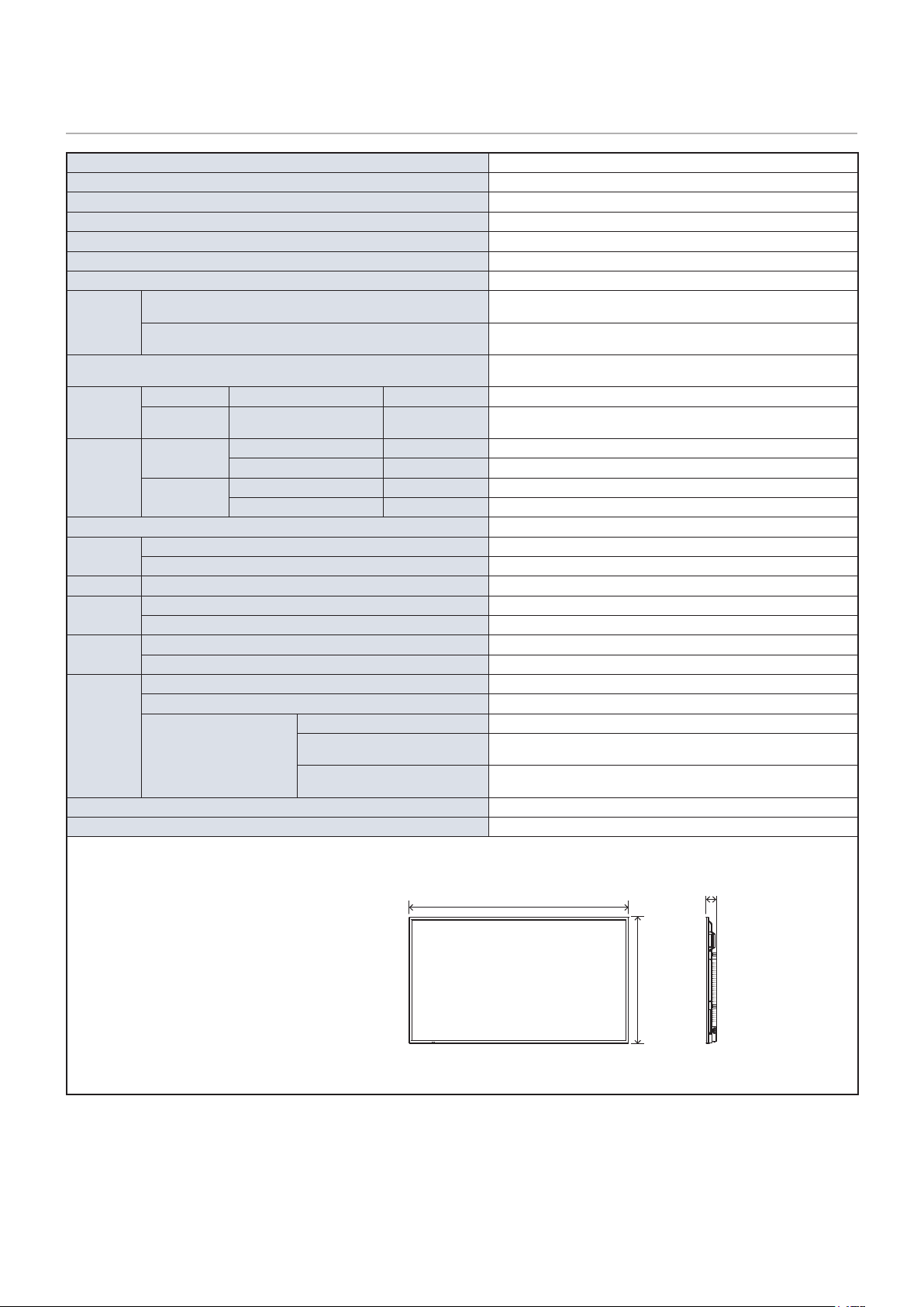
65
PN-HC751
Size (display size) 75”/1,892.74 mm diagonal
Type of LCD Active Matrix Color TFT LCD
Viewable Size 1,649.664 x 927.936 mm
Resolution 3840 x 2160
Pixel Pitch 0.43 mm (H) x 0.43 mm (V)
Color Over 1073 million colors
Brightness 450 cd/m
2
(Max.)
Frequency
Horizontal
31 - 83 kHz (analog input)
15.625/15.734 kHz, 31 - 136 kHz (digital input)
Vertical
56 Hz, 60 Hz, 70 Hz, 75 Hz (analog input)
24 Hz, 30 Hz, 50 Hz, 60 Hz, 70 Hz, 75 Hz (digital input)
Pixel Clock
13.5 MHz, 25 MHz - 156 MHz (analog input)
25 MHz - 600 MHz (digital input)
Input
Terminals
VGA (RGB) Mini D-sub 15 pin Analog RGB signal 0.7 Vp-p/75 Ω
HDMI HDMI terminal
Digital YUV
Digital RGB
HDMI, HDCP2.2, Compatible with HDMI-CEC
Audio
Terminals
Audio input
Stereo Mini Jack 3.5 mm Ø Analog audio signal Stereo L/R 0.5 Vrms
HDMI terminal Digital audio signal PCM 2 ch 32, 44.1, 48 kHz (16/20/24 bits)
Audio output
Stereo Mini Jack 3.5 mm Ø Analog audio signal The output sound varies depending on the input mode.
HDMI (ARC) terminal
*1
Digital audio signal PCM 2 ch 32, 44.1, 48 kHz (16/20/24 bits)
Speaker Output Internal Speakers 10 W + 10 W (Stereo)
Control
Terminals
RS-232C 9 Pin D-sub x1
LAN RJ-45 10BASE-T / 100BASE-TX
USB Terminal USB Type-A port For media player/rmware update, DC 5 V / 500 mA (max)
Operational
Environment
Temperature 0 - 40 °C / 32 - 104 °F
Humidity 20 - 80 % (without condensation)
Storage
Environment
Temperature –20 - 60 °C / –4 - 140 °F
Humidity 10 - 90 % (without condensation)
Power Supply
Power input AC 100 - 240 V 50/60 Hz
Input current 2.7 A
Consumption
Full operation 240 W (standard value)
Standby mode (when LAN function is
enabled)
2.0 W or less
*2
Standby mode (when LAN function is
disabled)
0.5 W or less
*2
Weight Approx. 34 kg (75.0 lbs)
Inclination Angle ±20°
Dimensions
*1 HDMI1 only.
*2 When used with the default
settings.
66-5/8 (1,692.5)
3-1/8
(79.8)
38-3/16 (970.7)
Technical specications are subject to change without notice. Unit: inch (mm)
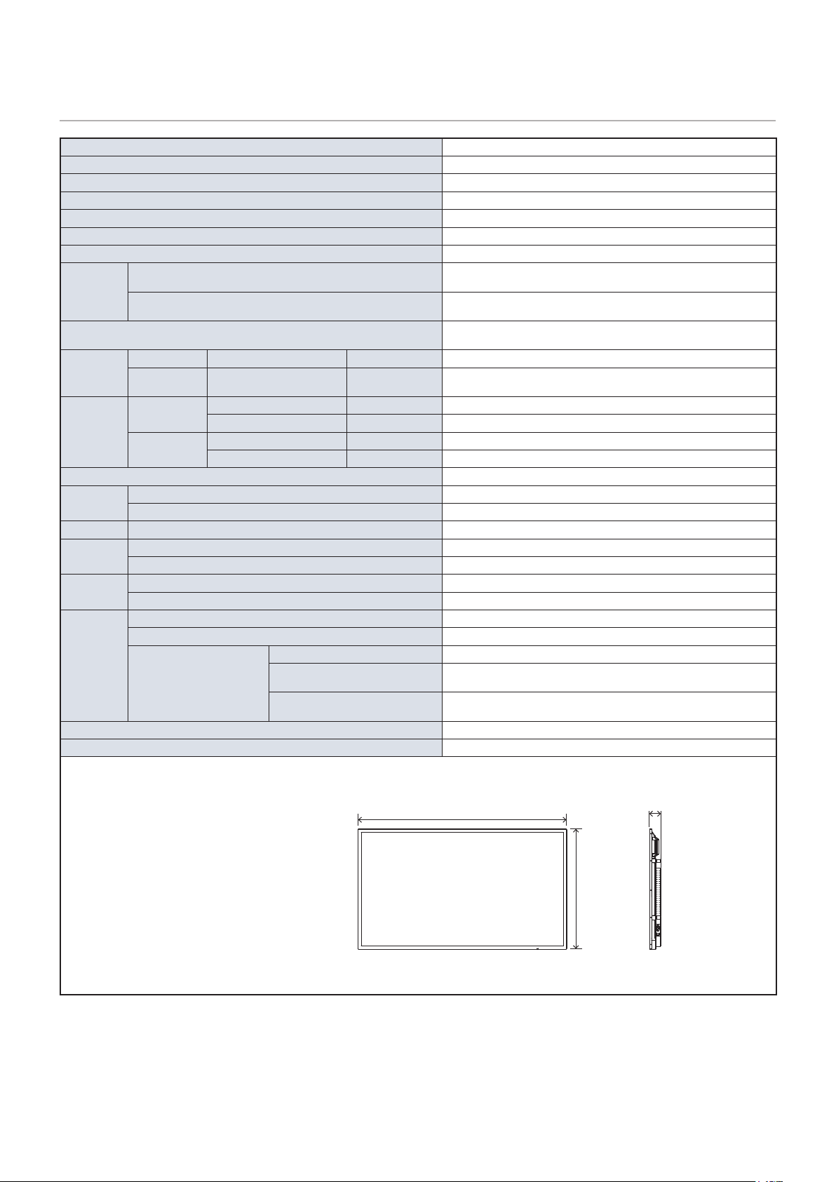
66
PN-HC651
Size (display size) 65”/1,638.96 mm diagonal
Type of LCD Active Matrix Color TFT LCD
Viewable Size 1428.48 x 803.52 mm
Resolution 3840 x 2160
Pixel Pitch 0.372 mm (H) x 0.372 mm (V)
Color Over 1073 million colors
Brightness 450 cd/m
2
(Max.)
Frequency
Horizontal
31 - 83 kHz (analog input)
15.625/15.734 kHz, 31 - 136 kHz (digital input)
Vertical
56 Hz, 60 Hz, 70 Hz, 75 Hz (analog input)
24 Hz, 30 Hz, 50 Hz, 60 Hz, 70 Hz, 75 Hz (digital input)
Pixel Clock
13.5 MHz, 25 MHz - 156 MHz (analog input)
25 MHz - 600 MHz (digital input)
Input
Terminals
VGA (RGB) Mini D-sub 15 pin Analog RGB signal 0.7 Vp-p/75 Ω
HDMI HDMI terminal
Digital YUV
Digital RGB
HDMI, HDCP2.2, Compatible with HDMI-CEC
Audio
Terminals
Audio input
Stereo Mini Jack 3.5 mm Ø Analog audio signal Stereo L/R 0.5 Vrms
HDMI terminal Digital audio signal PCM 2 ch 32, 44.1, 48 kHz (16/20/24 bits)
Audio output
Stereo Mini Jack 3.5 mm Ø Analog audio signal The output sound varies depending on the input mode.
HDMI (ARC) terminal
*1
Digital audio signal PCM 2 ch 32, 44.1, 48 kHz (16/20/24 bits)
Speaker Output Internal Speakers 10 W + 10 W (Stereo)
Control
Terminals
RS-232C 9 Pin D-sub x1
LAN RJ-45 10BASE-T / 100BASE-TX
USB Terminal USB Type-A port For media player/rmware update, DC 5 V / 500 mA (max)
Operational
Environment
Temperature 0 - 40 °C / 32 - 104 °F
Humidity 20 - 80 % (without condensation)
Storage
Environment
Temperature –20 - 60 °C / –4 - 140 °F
Humidity 10 - 90 % (without condensation)
Power Supply
Power input AC 100 - 240 V 50/60 Hz
Input current 2.2 A
Consumption
Full operation 190 W (standard value)
Standby mode (when LAN function is
enabled)
2.0 W or less
*2
Standby mode (when LAN function is
disabled)
0.5 W or less
*2
Weight Approx. 28 kg (61.8 lbs)
Inclination Angle ±20°
Dimensions
*1 HDMI1 only.
*2 When used with the default
settings.
58-1/8 (1,476.7)
3-1/16
(78.3)
33-9/16 (851.7)
Technical specications are subject to change without notice. Unit: inch (mm)

67
Appendix A Trademark and Software
License
Microsoft and Windows are trademarks of the Microsoft group of companies.
The terms HDMI and HDMI High-Denition Multimedia Interface, and the HDMI Logo are trademarks or registered trademarks
of HDMI Licensing Administrator, Inc. in the United States and other countries.
Blu-ray is a trademark of Blu-ray Disc Association.
Intel is a trademark of Intel Corporation or its subsidiaries.
Google is a trademark or registered trademarks of Google LLC.
All other brand and product names are trademarks or registered trademarks of their respective holders.
Noto Sans CJK JP Regular
Copyright 2012 Google Inc. All Rights Reserved.
This Font Software is licensed under the SIL Open Font License, Version 1.1.
(https://fonts.google.com/noto/specimen/Noto+Sans+JP)
[Notice] About the MPEG-4 AVC, MPEG-4 Visual license included in this product
1. MPEG AVC
THIS PRODUCT IS LICENSED UNDER THE AVC PATENT PORTFOLIO LICENSE FOR THE PERSONAL USE OF
A CONSUMER OR OTHER USES IN WHICH IT DOES NOT RECEIVE REMUNERATION TO (i) ENCODE VIDEO IN
COMPLIANCE WITH THE AVC STANDARD (“AVC VIDEO”) AND/OR (ii) DECODE AVC VIDEO THAT WAS ENCODED BY
A CONSUMER ENGAGED IN A PERSONAL ACTIVITY AND/OR WAS OBTAINED FROM A VIDEO PROVIDER LICENSED
TO PROVIDE AVC VIDEO. NO LICENSE IS GRANTED OR SHALL BE IMPLIED FOR ANY OTHER USE. ADDITIONAL
INFORMATION MAY BE OBTAINED FROM MPEG LA, L.L.C. SEE HTTP://WWW.MPEGLA.COM
2. MPEG-4 Visual
THIS PRODUCT IS LICENSED UNDER THE MPEG-4 VISUAL PATENT PORTFOLIO LICENSE FOR THE PERSONAL AND
NON-COMMERCIAL USE OF A CONSUMER FOR (i) ENCODING VIDEO IN COMPLIANCE WITH THE MPEG-4 VISUAL
STANDARD (“MPEG-4 VIDEO”) AND/OR (ii) DECODING MPEG-4 VIDEO THAT WAS ENCODED BY A CONSUMER
ENGAGED IN A PERSONAL AND NONCOMMERCIAL ACTIVITY AND/OR WAS OBTAINED FROM A VIDEO PROVIDER
LICENSED BY MPEG LA TO PROVIDE MPEG-4 VIDEO. NO LICENSE IS GRANTED OR SHALL BE IMPLIED FOR
ANY OTHER USE. ADDITIONAL INFORMATION INCLUDING THAT RELATING TO PROMOTIONAL, INTERNAL AND
COMMERCIAL USES AND LICENSING MAY BE OBTAINED FROM MPEG LA, LLC. SEE HTTP://WWW.MPEGLA.COM.

68
Appendix B OSD Controls List
This Chapter Includes:
>
"Video Settings" on page 69
>
"Audio Settings" on page 71
>
"Setup" on page 72
>
"Control Settings" on page 74
>
"Media Player" on page 75
>
"Schedule" on page 76

69
Video Settings
Video
Picture Mode Provides pre-congured video settings suitable for various environments where this device
may be used, or customize settings to your preference.
HDR Video Video setting for the HDR format. (Can be selected only when an HDR signal is input.)
Dynamic High-contrast video setting.
Standard Standard setting.
Conferencing Video setting suited for video conferences.
HighBright Maximum backlight brightness with higher color temperature for brighter ambient environments.
Custom Customizable settings.
Advanced Video Menu used to adjust detailed video settings.
Aspect Ratio Select the aspect ratio of the screen image. For more information, see “Setting the Aspect
Ratio” in this manual.
Normal Maximizes the size without changing the aspect ratio.
1:1 Shows the image in a 1 by 1 pixel format. (If the input resolution is higher than the
recommended resolution, the image will be scaled down to t the screen).
Full Fills the entire screen even if the aspect ratio needs to be changed.
Zoom Fills the entire screen without changing the aspect ratio.
NOTE: The areas of the image that are outside of the active screen area are not shown.
Overscan Selects the image display area.
Auto The image display area is set automatically.
On Approximately 95 % of the image will be shown on the screen.
Off The whole image is displayed within the screen area. This setting may cause noise at the
edges of the screen depending on the signal.
NOTE: When you use a computer with an HDMI output, set it to [OFF].
Color Temperature Adjusts the color temperature of the entire screen.
A low color temperature will result in a reddish screen. A high color temperature will make the
screen bluish.
If a temperature needs further adjustment, the individual R/G/B/ levels of the white point can
be adjusted.
Cool High color temperature setting. The screen will be bluish.
Normal Intermediate setting.
Warm Low color temperature setting. The screen will be reddish.
Native Turns the color temperature adjustment off and displays the image with the panel
characteristics.
Custom Customizable settings.
Noise Reduction Reduces the image noise.
Adaptive Contrast Adjusts automatically the contrast according to the image. If [High] is set, the image is shown
clearly but the brightness variation may appear not natural.

70
Video
Gamma Adjusts the brightness of gray and other intermediate colors. (SDR)
Native Gamma correction is handled by the LCD panel.
2.2 Typical monitor gamma for use with a computer.
2.4 Typical gamma settings for use with video devices, such as DVDs and Blu-rays.
Color Enhance Changes the colors of the image and the saturation to create a more colorful image.
HDR Mode When the monitor detects an HDR signal, you can select preferred gamma correction from
[Low], [Mid] and [High].
Backlight / Brightness Adjusts the brightness of the image using the backlight.
Press the
t
and
u
the buttons to adjust the brightness. In general, use this function to adjust
the brightness.
Contrast Adjusts the contrast.
Press the
t
and
u
the buttons to adjust the contrast.
Video Black Level Set the black level of the screen. When the setting is too low to show, the OSD characters are
changed to green.
Sharpness Adjusts the sharpness of the image.
Press the
u
button to sharpen the image, or the
t
button to soften it.
Color Adjusts the color density of the screen.
Press the
u
button to increase the density, or the
t
button to decrease it.
Tint Adjusts the tint of the image between R0-R50 and G0-G50.
Reset Video Settings Returns all settings in the Video Settings to their default values.

71
Audio Settings
Audio
Sound Mode Set pre-congured audio settings suitable for various environments where the monitor may be
used, or customize settings to your preference.
Standard Standard sound setting.
Music Optimized settings for music playback or audio in conference rooms.
Movie Surround sound for clarity in retail stores and other signage applications.
Custom Customizable settings.
Balance Press the
u
button to move the audio signal to the right. Press the
t
button to move the audio
signal to the left.
Surround Articially produces surround sound audio.
Internal Speakers Congures the settings for the internal speakers output. This setting is enabled when Disable
is selected for Audio receiver.
Auto The sound is not output from the internal speakers when a cable is connected to the AUDIO
OUT terminal.
Off Sound is not output from the internal speakers.
On Sound is always output from the internal speakers.
Audio Input Selects whether to use the audio signal of the Audio In terminal when the audio signal is not
included in the HDMI signal (DVI signals, etc.).
HDMI:
The HDMI terminal is used.
Audio in:
The AUDIO IN terminal is used.
Audio Delay Adjusts the delay time until the audio is output.
Reset Audio Settings Returns all settings in the Audio Settings to their default values.

72
Setup
Setup
OSD Settings
Language Select the language used in the OSD.
Transparency Set the transparency level of the OSD menu between 30%, 50%, 70% and Off.
The higher the percentage, the more transparent is the OSD menu.
Information OSD Displays or hides the Information OSD.
Information OSD contains the messages that are displayed on the screen when the input is
switched or when the state of the input signal changes.
Power save settings
Energy Mode Select a mode between Home, Retail, and Ofce.
For more information, see “Energy Mode” page 30.
Clock Sets the time until the monitor enters the Power Save mode. When the set time has elapsed
after the input signal has been lost, the Power Save function is activated.
Auto Power Down When turned On, the monitor turns automatically off after 4 hours without any operation.
Auto Input Change When there are several inputs, this function switches automatically to the terminal to which a
signal is input.
Press the INFORMATION button of the remote control to display the selected input terminal on
INFORMATION1.
NOTE: This setting or USB Demo Mode cannot be used simultaneously.
None The input terminal is changed manually.
On If the signal is lost in the input terminal being displayed, the monitor searches automatically
another terminal with an input signal and switches to it.
The display does not change if a new signal is input into a terminal different from the terminal
currently being displayed.
Custom The input terminals included in the search performed by the monitor can be selected.
NOTE: If [Custom] is selected, the monitor will not switch to an input signal not set in
[Search terminal].
HDMI Settings
CEC This function makes it possible to control a device supporting HDMI CEC connected to the
HDMI terminal.
When set to On, HDMI CEC is enabled.
EDID Sets the HDMI mode.
Mode 0:
Max resolution is 1920 x 1080 (60 Hz).
Mode 1:
Max resolution is 3840 x 2160 (30 Hz).
Mode 2:
Max resolution is 3840 x 2160 (60 Hz), HDCP 2.2, or HDR.
Video Range Adjust the gradation range to be shown according to the video signal to improve the whiteout
and blackout of the image.
HPD Delay This function makes it possible to control the time until the video from the HDMI terminal is
displayed.
When set to Off, the time until the video is output can be reduced but the video may not be
output depending on the device. In such a case, set [HPD Delay] to On.

73
Setup
VGA Options Enabled when a VGA signal is input.
Auto Adjust Automatically adjusts settings such as the image position.
Clock Adjust this setting when vertical lines appear on the screen or when the size differs at the right
and left of the screen.
Phase Adjust this setting when noise appears in the horizontal direction, when the characters are
blurred, or when the contours are not sharp.
H.Position Adjusts the horizontal position of the screen.
Press the
u
button to move the screen to the right or the
t
button to move it to the left.
V.Position Adjusts the vertical position of the screen.
Press the
u
button to move the screen to the top or the
t
button to move it to the bottom.
H.Resolution The video can be enlarged/reduced in the horizontal direction using this function only when
[Standard] is selected in [Aspect Ratio].
NOTE: This function may not operate depending on the input signal.
V.Resolution The video can be enlarged/reduced in the vertical direction using this function only when
[Standard] is selected in [Aspect Ratio].
NOTE: This function may not operate depending on the input signal.
Reset VGA Options Resets the VGA Options settings to their default values.
Other settings
Input Labels Renames the input terminal currently being displayed. Letters (A-Z), numbers (0-9), and some
symbols can be used.
Key Lock Settings Prevents the monitor from being controlled using the buttons on the monitor control panel.
Off:
All buttons operate normally.
Mode 1:
Only the power button and the input mode switching function operate.
Mode 2:
All buttons are locked. (Only the power button can be used during standby mode.)
IR Lock Settings Prevents the monitor from being controlled using the remote control.
Off:
All buttons operate normally.
Mode 1:
Only the POWER and the INPUT buttons operate.
Mode 2:
All buttons are locked. (Only the POWER button can be used during standby
mode.)
LED Indicator Set it to Off to turn off the power indicator when the monitor is turned on (normally lit green).
Mute Settings You can change the effect of the MUTE button of the remote control.
Audio:
Mutes only the audio les.
Video:
Mutes only the video les.
Audio & Video:
Mutes the audio and the video les.
ROTATE 180° You can rotate the video 180 degrees.
Thermal Management You can select the vertical or horizontal installation direction in the sensor settings.
The monitor is equipped with thermal sensors and displays a warning when the ambient
temperature exceeds the operation guaranteed temperature. If a warning is displayed, turn the
monitor off since using the monitor in such environment may cause a malfunction.
Warning Message:
A temperature warning is displayed on the screen when the internal
temperature has exceeded the operation guaranteed temperature.
Shutdown:
The monitor turns off automatically when the internal temperature has
exceeded the operation guaranteed temperature.
Signal Information Displays the information regarding the input signal.
Monitor Information Displays the information regarding the monitor.
Factory Reset All settings except network are returned to factory default.

74
Control Settings
Control Settings
Control Interface NOTE: Only one method, LAN or RS-232, can be used at the same time.
LAN Sets network (LAN) control.
RS-232C Sets RS-232C control.
Network Settings Congures the network settings of the monitor.
DHCP
On:
Obtains the network settings from the DHCP server on the network.
Off:
Sets xed networks settings.
Manual DNS:
Obtain the network settings from the DHCP server on the network but the DNS
is set manually.
IP ADDRESS Set the IP address of the monitor when [DHCP] is set to [Off].
SUBNET MASK Set the subnet mask for the network to which the monitor is connected when [Off] is selected
for [DHCP].
DEFAULT GATEWAY Set the default gateway for the network to which the monitor is connected when [Off] is
selected for [DHCP].
DNS PRIMARY Enter the IP address of the primary DNS server of the network connected to the monitor.
NOTE: Enter [0.0.0.0] to delete the setting.
DNS SECONDARY Enter the IP address of the secondary DNS server of the network connected to the monitor.
NOTE: Enter [0.0.0.0] to delete the setting.
MAC ADDRESS Shows the monitor’s MAC ADDRESS.
This cannot be changed.
SAVE Saves the settings.
Reset Network Settings Returns the network settings to their default values.

75
Shows the monitor’s MAC
ADDRESS.
This cannot be changed.
Media Player
Media Player
USB Demo Mode Photos (still pictures), music and video les saved in the “DEMO” folder in the USB storage
device can be played automatically.
You can select the types of les to play in the USB Demo Mode.
NOTE:
Enabling USB Demo Mode
To enable the USB Demo Mode, [Energy Mode] in the [Setup] menu must be set to [Retail].
NOTE:
Starting USB Demo Mode
The playback of the les starts automatically under the following conditions.
• The USB Demo Mode has been enabled.
• A folder named “DEMO” exists in the USB storage device.
• No signal is being input in a terminal other than the USB port.
• There was no user operation for 10 seconds or more.
NOTE:
Memo
• The POWER, VOLUME, and MUTE buttons of the remote control operate normally. If other buttons
are pressed, the playback stops and the input returns to the terminal used previously.
• The playback is also stopped is the USB storage device is removed.
• If the monitor is turned off during playback in USB Demo Mode, the next time the monitor is turned
on, playback will start automatically if the USB storage device is still connected.
• This setting or Auto Input Change cannot be used simultaneously.
UnPlug USB Device Select [Execute] before removing the USB device.
Caution Window Sets whether to display a caution window (On) or not (Off) when a le with a format or a codec
not supported by the monitor is played.

76
Schedule
Schedule
Sleep Timer Sets the time until the monitor turns off automatically.
Off
,
10 minutes
,
15 minutes
,
30 minutes
,
60 minutes
,
90 minutes
,
120 minutes
,
180
minutes
,
240 minutes
can be selected.
Current Time settings Sets the current time.
NOTE:
• If the monitor remains for two weeks or more with the power cord unplugged, the clock will not show
the correct time.
In this case, set the [Current Time settings] again.
• Check regularly that the set date and time are correct.
Schedule settings
Power On:
Sets the time when the monitor will turn on.
Power Off:
Sets the time when the monitor will turn off.

77
Appendix C Others
This Chapter Includes:
>
"RS-232C command table" on page 78
>
"Intellectual Property Rights and Other Matters" on page 80
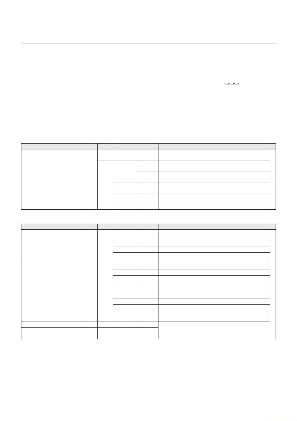
78
RS-232C command table
How to read the command table
Command: Command eld
Direction: W When the “Parameter” is set in the parameter eld, the command functions as described under “Control/
Response Contents”.
R The returned value indicated under “Reply” can be obtained by setting “????” or “
?” in the
parameter eld.
Parameter: Parameter eld
Reply: Response
* : “●” : Indicates a command which can be used in standby state, input signal waiting state or when the power is on.
“–” : Indicates a command which can be used when the power is on.
Power control/Input mode selection
Function
Command
Direction
Parameter Reply Control/Response contents
*
POWER CONTROL POWR W 0
Switches to standby state.
●
1 Returns from standby state.
R 0 Standby state
1 Normal mode
2 Input signal waiting state
INPUT MODE SELECTION INPS WR 0 Toggle change for input mode.
-
2 2 VGA (RGB)
10 10 HDMI1
11 11 Media Player
13 13 HDMI2
18 18 HDMI3
PICTURE menu
Function
Command
Direction
Parameter Reply Control/Response contents *
BRIGHT VLMP WR 0-100 0-100
-
SIZE (Changing aspect ratio) WIDE WR 1 1 Full
2 2 Normal
3 3 1:1
4 4 Zoom
COLOR MODE BMOD WR 0 0 Standard
2 2 Dynamic
4 4 HighBright
5 5 Conferencing
8 8 Custom
11 11 HDR Video
WHITE BALANCE CTMP WR 0 0 Native
8 8 Warm
17 17 Normal
22 22 Cool
99 99 Custom
R-CONTRAST CRTR WR 0-255 0-255 The contrast value when the Color Temperature is set to Custom.
Error if the Color Temperature is not set to custom.
G-CONTRAST CRTG WR 0-255 0-255
B-CONTRAST CRTB WR 0-255 0-255
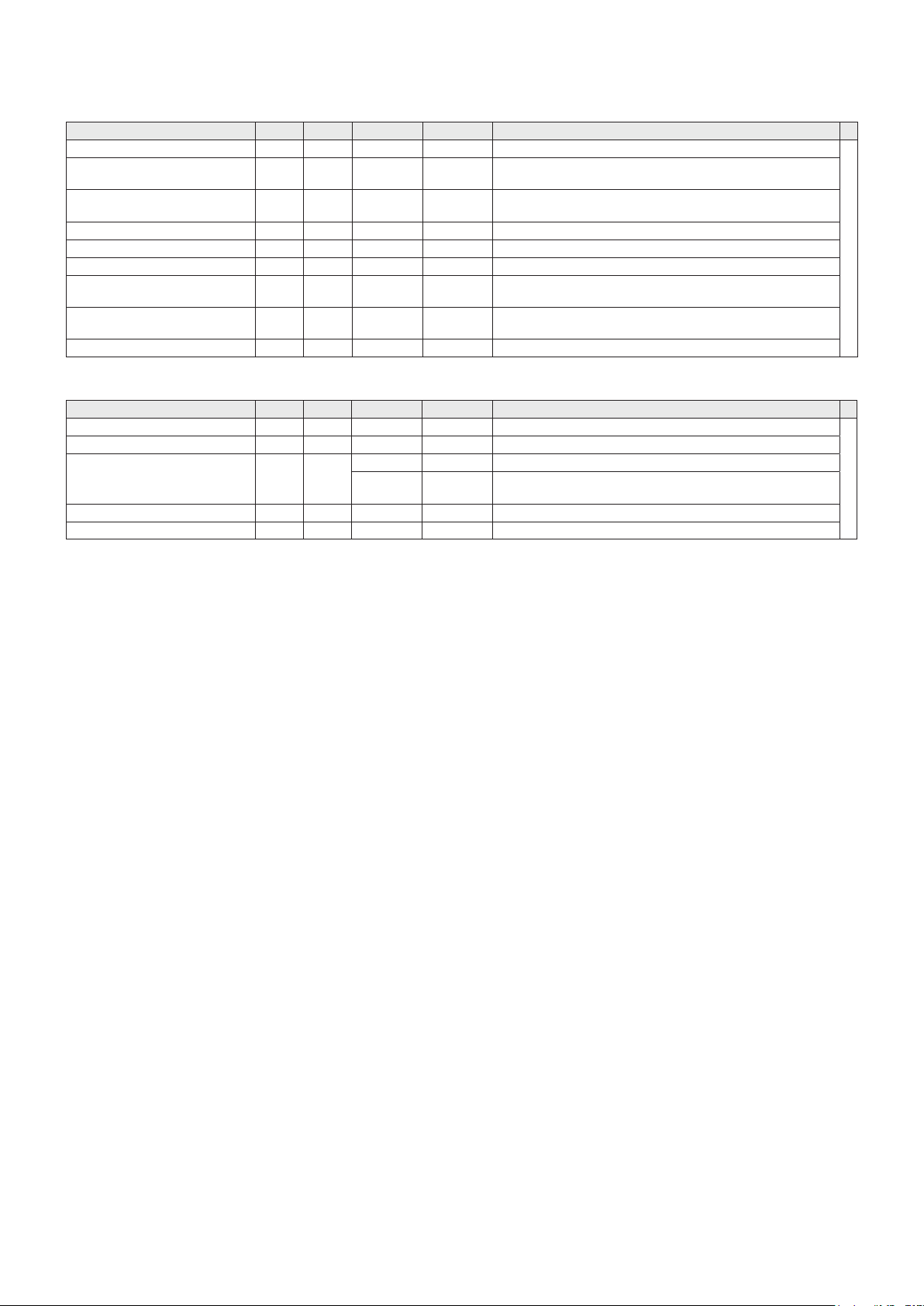
79
SETUP menu
Function
Command
Direction
Parameter Reply Control/Response contents
*
TIME SETTING DATE WR AABB AABB AA: Hour, BB: Minute
-
User name USER WR XXXXXXXX XXXXXXXX User name when controlling the monitor via RS-232C commands with
LAN. USER command is enabled when Control Interface is set to LAN.
Password PASS WR XXXXXXXX XXXXXXXX Password when controlling the monitor via RS-232C commands with
LAN. PASS command is enabled when Control Interface is set to LAN.
SENSOR SETTING STDR WR 0-1 0-1 0: LANDSCAPE, 1: PORTRAIT
Model INF1 R Value
Serial no. SRNO R Value
Key Lock Settings ALCM WR 0-2 0-2 0: Off, 1: All buttons are locked, 2: Only the power button and the input
mode switching function operate
IR Lock Settings ALCR WR 0-1, 3 0-1, 3 0: Off, 1: All buttons are locked (Mode 2), 2: Only the POWER and the
INPUT buttons operate (Mode 1)
ALL RESET RSET W 0 0 Initialization
Others
Function
Command
Direction
Parameter Reply Control/Response contents *
VOLUME VOLM WR 0-100 0-100
-
MUTE AUDIO MUTE WR 0-1 0-1 0: OFF, 1: ON
Temperature sensor DSTA R 0 0 Internal temperature normal
3 3 Internal temperature has exceeded the operation guaranteed
temperature
Temperature acquisition ERRT R Value Returns the temperature at the temperature sensors.
Check the resolution PXCK R Value Returns current resolution.

80
Information on the software license for this
product
Software composition
The software included in this product is comprised of
various software components whose individual copyrights
are held by SHARP or by third parties�
This product makes use of freely distributed software and
software components whose copyrights are held by third
parties� These include software components covered by
a GNU General Public License (hereafter GPL), a GNU
Lesser General Public License (hereafter LGPL) and an
Apache License�
Obtaining source code
Some of the open source software licensors require the
distributor to provide the source code with the executable
software components� GPL and LGPL include similar
requirements�
We are unable to answer any questions about the source
code for the open source software� The source code for the
software components whose copyrights are held by SHARP
is not distributed�
Acknowledgements
The following open source software components are
included in this product:
Ethtool, ser2net, lua-cjson, libhtttpd, glibc, libjson, lua,
libbubox, uhttpd, netifd, Linux Kernel, fstools, ubox, zlib,
util-linux, procd, usingn, luci-theme-boot-strap, luci-base,
busybox, linux-rmware, libgcrypt, libgpg-error, Noto Fonts
Intellectual Property Rights and Other Matters
Software copyrights
Ethtool v3�18
Ethtool is available under the terms of the GNU Public License version 2�
ser2net 2�10�0-2
GNU GENERAL PUBLIC LICENSE
Version 2, June 1991
netifd 2015-12-16
netifd - network interface daemon
Copyright (C) 2012 Felix Fietkau <nbd@openwrt�org>
This program is free software; you can redistribute it and/or modify it under the
terms of the GNU General Public License version 2 as published by the Free
Software Foundation
This program is distributed in the hope that it will be useful, but WITHOUT ANY
WARRANTY; without even the implied warranty of MERCHANTABILITY or FITNESS
FOR A PARTICULAR PURPOSE� See the GNU General Public License for more
details�
busybox 1�23�2
BusyBox is distributed under version 2 of the General Public License (included in
its entirety, below)� Version 2 is the only version of this license which this version of
BusyBox (or modied versions derived from this one) may be distributed under.
ubox 2015-11-22
procd 2015-10-29�1
Copyright (C) 2013 Felix Fietkau <nbd@openwrt�org>
Copyright (C) 2013 John Crispin <blogic@openwrt�org>
This program is free software; you can redistribute it and/or modify it under the
terms of the GNU Lesser General Public License version 2�1 as published by the
Free Software Foundation
This program is distributed in the hope that it will be useful, but WITHOUT ANY
WARRANTY; without even the implied warranty of MERCHANTABILITY or FITNESS
FOR A PARTICULAR PURPOSE� See the GNU General Public License for more
details�
fstools 2016-01-10
* Copyright (C) 2013 Felix Fietkau nbd@openwrt�org
* Copyright (C) 2013/2014 John Crispin <blogic@openwrt�org>
This program is free software; you can redistribute it and/or modify it under the
terms of the GNU Lesser General Public License version 2�1 as published by the
Free Software Foundation
This program is distributed in the hope that it will be useful, but WITHOUT ANY
WARRANTY; without even the implied warranty of MERCHANTABILITY or FITNESS
FOR A PARTICULAR PURPOSE� See the GNU General Public License for more
details�
glibc
GNU Lesser General Public License
kernel 3�18�109
GNU General Public License version 2
usign 2015-05-08
usign - tiny signify replacement
Copyright (C) 2015 Felix Fietkau <nbd@openwrt�org>
Permission to use, copy, modify, and/or distribute this software for any purpose
with or without fee is hereby granted, provided that the above copyright notice and
this permission notice appear in all copies�
THE SOFTWARE IS PROVIDED "AS IS" AND THE AUTHOR DISCLAIMS ALL
WARRANTIES WITH REGARD TO THIS SOFTWARE INCLUDING ALL IMPLIED
WARRANTIES OF MERCHANTABILITY AND FITNESS� IN NO EVENT SHALL
THE AUTHOR BE LIABLE FOR ANY SPECIAL, DIRECT, INDIRECT, OR
CONSEQUENTIAL DAMAGES OR ANY DAMAGES WHATSOEVER RESULTING
FROM LOSS OF USE, DATA OR PROFITS, WHETHER IN AN ACTION OF
CONTRACT, NEGLIGENCE OR OTHER TORTIOUS ACTION, ARISING OUT OF OR
IN CONNECTION WITH THE USE OR PERFORMANCE OF THIS SOFTWARE�

81
luci-theme-bootstrap 2015-05-08
LuCI Theme Bootstrap: Copyright 2012 Nut & Bolt Twitter Bootstrap: Copyright 2011
Twitter, Inc�
Licensed under the Apache License, Version 2�0 (the "License");
you may not use this le except in compliance with the License.
You may obtain a copy of the License at
http://www�apache�org/licenses/LICENSE-2�0
Unless required by applicable law or agreed to in writing, software distributed
under the License is distributed on an "AS IS" BASIS, WITHOUT WARRANTIES OR
CONDITIONS OF ANY KIND, either express or implied�
See the License for the specic language governing permissions and limitations
under the License�
luci-base
Copyright (C) 2008-2015 The LuCI Team <luci@lists�subsignal�org>
Licensed under the Apache License, Version 2�0 (the "License");
you may not use this le except in compliance with the License.
You may obtain a copy of the License at
http://www�apache�org/licenses/LICENSE-2�0
Unless required by applicable law or agreed to in writing, software distributed
under the License is distributed on an "AS IS" BASIS, WITHOUT WARRANTIES OR
CONDITIONS OF ANY KIND, either express or implied�
See the License for the specic language governing permissions and limitations
under the License�
linux-rmware 2016-01-25
Copyright (c) 2015, Qualcomm Atheros, Inc�
All rights reserved�
Redistribution. Reproduction and redistribution in binary form, without modication,
for use solely in conjunction with a Qualcomm Atheros, Inc�
chipset, is permitted provided that the following conditions are met:
• Redistributions must reproduce the above copyright notice and the following
disclaimer in the documentation and/or other materials provided with the
distribution�
• Neither the name of Qualcomm Atheros, Inc� nor the names of its suppliers may be
used to endorse or promote products derived from this Software without specic
prior written permission�
• No reverse engineering, decompilation, or disassembly of this Software is
permitted�
Limited patent license� Qualcomm Atheros, Inc� (“Licensor”) grants you (“Licensee”)
a limited, worldwide, royalty-free, non-exclusive license under the Patents to make,
have made, use, import, offer to sell and sell the Software� No hardware per se is
licensed hereunder�
The term “Patents” as used in this agreement means only those patents or patent
applications owned solely and exclusively by Licensor as of the date of Licensor's
submission of the Software and any patents deriving priority (i.e., having a rst
effective ling date) therefrom. The term “Software” as used in this agreement means
the rmware image submitted by Licensor, under the terms of this license, to git://git.
kernel.org/pub/scm/linux/kernel/git/rmware/linux-rmware.git.
Notwithstanding anything to the contrary herein, Licensor does not grant and
Licensee does not receive, by virtue of this agreement or the Licensor's submission
of any Software, any license or other rights under any patent or patent application
owned by any afliate of Licensor or any other entity (other than Licensor), whether
expressly, impliedly, by virtue of estoppel or exhaustion, or otherwise�
DISCLAIMER� THIS SOFTWARE IS PROVIDED BY THE COPYRIGHT HOLDERS
AND CONTRIBUTORS "AS IS" AND ANY EXPRESS OR IMPLIED WARRANTIES,
INCLUDING, BUT NOT LIMITED TO, THE IMPLIED WARRANTIES OF
MERCHANTABILITY AND FITNESS FOR A PARTICULAR PURPOSE ARE
DISCLAIMED� IN NO EVENT SHALL THE COPYRIGHT OWNER OR CONTRIBUTORS
BE LIABLE FOR ANY DIRECT, INDIRECT,
INCIDENTAL, SPECIAL, EXEMPLARY, OR CONSEQUENTIAL DAMAGES
(INCLUDING, BUT NOT LIMITED TO, PROCUREMENT OF SUBSTITUTE GOODS
OR SERVICES; LOSS OF USE, DATA, OR PROFITS; OR BUSINESS INTERRUPTION)
HOWEVER CAUSED AND ON ANY THEORY OF LIABILITY, WHETHER IN
CONTRACT, STRICT LIABILITY, OR TORT (INCLUDING NEGLIGENCE OR
OTHERWISE) ARISING IN ANY WAY OUT OF THE USE OF THIS SOFTWARE, EVEN
IF ADVISED OF THE POSSIBILITY OF SUCH DAMAGE�
Lighttpd 1�4�45
Copyright (c) 2004, Jan Kneschke, incremental
All rights reserved�
Redistribution and use in source and binary forms, with or without modication, are
permitted provided that the following conditions are met:
- Redistributions of source code must retain the above copyright notice, this list of
conditions and the following disclaimer�
- Redistributions in binary form must reproduce the above copyright notice, this list of
conditions and the following disclaimer in the documentation and/or other materials
provided with the distribution�
- Neither the name of the 'incremental' nor the names of its contributors may be used
to endorse or promote products derived from this software without specic prior
written permission�
THIS SOFTWARE IS PROVIDED BY THE COPYRIGHT HOLDERS AND
CONTRIBUTORS "AS IS" AND ANY EXPRESS OR IMPLIED WARRANTIES,
INCLUDING, BUT NOT LIMITED TO, THE IMPLIED WARRANTIES OF
MERCHANTABILITY AND FITNESS FOR A PARTICULAR PURPOSE ARE
DISCLAIMED� IN NO EVENT SHALL THE COPYRIGHT OWNER OR CONTRIBUTORS
BE LIABLE FOR ANY DIRECT, INDIRECT, INCIDENTAL, SPECIAL, EXEMPLARY, OR
CONSEQUENTIAL DAMAGES (INCLUDING, BUT NOT LIMITED TO, PROCUREMENT
OF SUBSTITUTE GOODS OR SERVICES; LOSS OF USE, DATA, OR PROFITS;
OR BUSINESS INTERRUPTION) HOWEVER CAUSED AND ON ANY THEORY OF
LIABILITY, WHETHER IN CONTRACT, STRICT LIABILITY, OR TORT (INCLUDING
NEGLIGENCE OR OTHERWISE) ARISING IN ANY WAY OUT OF THE USE OF THIS
SOFTWARE, EVEN IF ADVISED OF THE POSSIBILITY OF SUCH DAMAGE�
lua-cjson 2�1�0
Copyright (c) 2010-2012 Mark Pulford <mark@kyne�com�au>
Permission is hereby granted, free of charge, to any person obtaining a copy of this
software and associated documentation les (the "Software"), to deal in the Software
without restriction, including without limitation the rights to use, copy, modify,
merge, publish, distribute, sublicense, and/or sell copies of the Software, and to
permit persons to whom the Software is furnished to do so, subject to the following
conditions:
The above copyright notice and this permission notice shall be included in all copies
or substantial portions of the Software�
THE SOFTWARE IS PROVIDED "AS IS", WITHOUT WARRANTY OF ANY KIND,
EXPRESS OR IMPLIED, INCLUDING BUT NOT LIMITED TO THE WARRANTIES
OF MERCHANTABILITY, FITNESS FOR A PARTICULAR PURPOSE AND
NONINFRINGEMENT�
IN NO EVENT SHALL THE AUTHORS OR COPYRIGHT HOLDERS BE LIABLE FOR
ANY CLAIM, DAMAGES OR OTHER LIABILITY, WHETHER IN AN ACTION OF
CONTRACT, TORT OR OTHERWISE, ARISING FROM, OUT OF OR IN CONNECTION
WITH THE SOFTWARE OR THE USE OR OTHER DEALINGS IN THE SOFTWARE�
libjson-c 0�12
Copyright (c) 2009-2012 Eric Haszlakiewicz
Permission is hereby granted, free of charge, to any person obtaining a copy of this
software and associated documentation les (the Software"),to deal in the Software
without restriction, including without limitation the rights to use, copy, modify,
merge, publish, distribute, sublicense,and/or sell copies of the Software, and to
permit persons to whom the Software is furnished to do so, subject to the following
conditions:
The above copyright notice and this permission notice shall be included in all copies
or substantial portions of the Software�
THE SOFTWARE IS PROVIDED "AS IS", WITHOUT WARRANTY OF ANY KIND,
EXPRESS OR IMPLIED, INCLUDING BUT NOT LIMITED TO THE WARRANTIES
OF MERCHANTABILITY, FITNESS FOR A PARTICULAR PURPOSE AND
NONINFRINGEMENT� IN NO EVENT SHALL THE AUTHORS OR COPYRIGHT
HOLDERS BE LIABLE FOR ANY CLAIM, DAMAGES OR OTHER LIABILITY,
WHETHER IN AN ACTION OF CONTRACT, TORT OR OTHERWISE, ARISING FROM,
OUT OF OR IN CONNECTION WITH THE SOFTWARE OR THE USE OR OTHER
DEALINGS IN THE SOFTWARE�
Lua 5�1�5
Copyright (C) 1994-2012 Lua�org, PUC-Rio�
Permission is hereby granted, free of charge, to any person obtaining a copy of this
software and associated documentation les (the "Software"), to deal in the Software
without restriction, including without limitation the rights to use, copy, modify,
merge, publish, distribute, sublicense, and/or sell copies of the Software, and to
permit persons to whom the Software is furnished to do so, subject to the following
conditions:

82
The above copyright notice and this permission notice shall be included in all copies
or substantial portions of the Software�
THE SOFTWARE IS PROVIDED "AS IS", WITHOUT WARRANTY OF ANY KIND,
EXPRESS OR IMPLIED, INCLUDING BUT NOT LIMITED TO THE WARRANTIES
OF MERCHANTABILITY, FITNESS FOR A PARTICULAR PURPOSE AND
NONINFRINGEMENT� IN NO EVENT SHALL THE AUTHORS OR COPYRIGHT
HOLDERS BE LIABLE FOR ANY CLAIM, DAMAGES OR OTHER LIABILITY,
WHETHER IN AN ACTION OF CONTRACT, TORT OR OTHERWISE, ARISING FROM,
OUT OF OR IN CONNECTION WITH THE SOFTWARE OR THE USE OR OTHER
DEALINGS IN THE SOFTWARE�
Libubox 2015-11-08
Copyright (c) 2016, yubo
All rights reserved�
Redistribution and use in source and binary forms, with or without modication, are
permitted provided that the following conditions are met:
* Redistributions of source code must retain the above copyright notice, this list of
conditions and the following disclaimer�
* Redistributions in binary form must reproduce the above copyright notice, this
list of conditions and the following disclaimer in the documentation and/or other
materials provided with the distribution�
* Neither the name of the author nor the names of its contributors may be used to
endorse or promote products derived from this software without specic prior
written permission�
THIS SOFTWARE IS PROVIDED BY THE COPYRIGHT HOLDERS AND
CONTRIBUTORS "AS IS" AND ANY EXPRESS OR IMPLIED WARRANTIES,
INCLUDING, BUT NOT LIMITED TO, THE IMPLIED WARRANTIES OF
MERCHANTABILITY AND FITNESS FOR A PARTICULAR PURPOSE ARE
DISCLAIMED� IN NO EVENT SHALL THE COPYRIGHT OWNER OR CONTRIBUTORS
BE LIABLE FOR ANY DIRECT, INDIRECT, INCIDENTAL, SPECIAL, EXEMPLARY, OR
CONSEQUENTIAL DAMAGES (INCLUDING, BUT NOT LIMITED TO, PROCUREMENT
OF SUBSTITUTE GOODS OR SERVICES;
LOSS OF USE, DATA, OR PROFITS; OR BUSINESS INTERRUPTION) HOWEVER
CAUSED AND ON ANY THEORY OF LIABILITY, WHETHER IN CONTRACT, STRICT
LIABILITY, OR TORT (INCLUDING NEGLIGENCE OR OTHERWISE) ARISING IN
ANY WAY OUT OF THE USE OF THIS SOFTWARE, EVEN IF ADVISED OF THE
POSSIBILITY OF SUCH DAMAGE�
uhttpd 2015-11-08
uhttpd - Tiny single-threaded httpd
Copyright (C) 2010-2013 Jo-Philipp Wich <xm@subsignal�org>
Copyright (C) 2013 Felix Fietkau <nbd@openwrt�org>
Permission to use, copy, modify, and/or distribute this software for any purpose with
or without fee is hereby granted, provided that the above copyright notice and this
permission notice appear in all copies�
THE SOFTWARE IS PROVIDED "AS IS" AND THE AUTHOR DISCLAIMS ALL
WARRANTIES WITH REGARD TO THIS SOFTWARE INCLUDING ALL IMPLIED
WARRANTIES OF MERCHANTABILITY AND FITNESS� IN NO EVENT SHALL THE
AUTHOR BE LIABLE FOR ANY SPECIAL, DIRECT, INDIRECT, OR CONSEQUENTIAL
DAMAGES OR ANY DAMAGES WHATSOEVER RESULTING FROM LOSS OF USE,
DATA OR PROFITS, WHETHER IN AN ACTION OF CONTRACT, NEGLIGENCE OR
OTHER TORTIOUS ACTION, ARISING OUT OF OR IN CONNECTION WITH THE USE
OR PERFORMANCE OF THIS SOFTWARE�
libgcrypt
Libgcrypt - The GNU Crypto Library
------------------------------------
Version 1�6
Copyright (C) 1989,1991-2012 Free Software Foundation, Inc�
Copyright (C) 2012-2014 g10 Code GmbH
Copyright (C) 2013-2014 Jussi Kivilinna
Libgcrypt is free software. See the le AUTHORS for full copying notices, and
LICENSES for notices about contributions that require these additional notices to
be distributed�
License
-------
The library is distributed under the terms of the GNU Lesser General Public
License (LGPL); see the le COPYING.LIB for the actual terms. The helper
programs (e�g� gcryptrnd and getrandom) as well as the documentation are
distributed under the terms of the GNU General Public License (GPL); see the le
COPYING for the actual terms. The le LICENSES has notices about contributions
that require these additional notices are distributed�
Additional license notices for Libgcrypt� -*- org -*-
This le contains the copying permission notices for various les in the Libgcrypt
distribution which are not covered by the GNU Lesser General Public License (LGPL)
or the GNU General Public License (GPL)�
These notices all require that a copy of the notice be included in the accompanying
documentation and be distributed with binary distributions of the code, so be sure to
include this le along with any binary distributions derived from the GNU C Library.
* BSD_3Clause
For les:
- cipher/sha256-ssse3-amd64�S
- cipher/sha512-avx-amd64�S
- cipher/sha512-avx2-bmi2-amd64�S
- cipher/sha512-ssse3-amd64�S
#+begin_quote
Copyright (c) 2012, Intel Corporation
All rights reserved�
Redistribution and use in source and binary forms, with or without modication, are
permitted provided that the following conditions are met:
* Redistributions of source code must retain the above copyright notice, this list of
conditions and the following disclaimer�
* Redistributions in binary form must reproduce the above copyright notice, this
list of conditions and the following disclaimer in the documentation and/or other
materials provided with the distribution�
* Neither the name of the Intel Corporation nor the names of its contributors may be
used to endorse or promote products derived from this software without specic
prior written permission�
THIS SOFTWARE IS PROVIDED BY INTEL CORPORATION "AS IS" AND ANY
EXPRESS OR IMPLIED WARRANTIES, INCLUDING, BUT NOT LIMITED TO, THE
IMPLIED WARRANTIES OF MERCHANTABILITY AND FITNESS FOR A PARTICULAR
PURPOSE ARE DISCLAIMED� IN NO EVENT SHALL INTEL CORPORATION OR
CONTRIBUTORS BE LIABLE FOR ANY DIRECT, INDIRECT, INCIDENTAL, SPECIAL,
EXEMPLARY, OR CONSEQUENTIAL DAMAGES (INCLUDING, BUT NOT LIMITED
TO, PROCUREMENT OF SUBSTITUTE GOODS OR SERVICES; LOSS OF USE,
DATA, OR PROFITS; OR BUSINESS INTERRUPTION) HOWEVER CAUSED AND
ON ANY THEORY OF LIABILITY, WHETHER IN CONTRACT, STRICT LIABILITY, OR
TORT (INCLUDING NEGLIGENCE OR OTHERWISE) ARISING IN ANY WAY OUT OF
THE USE OF THIS SOFTWARE, EVEN IF ADVISED OF THE POSSIBILITY OF SUCH
DAMAGE�
#+end_quote
* Simple permissive licenses
For les:
- cipher/crc�c
#+begin_quote
Copyright (c) 1996 L� Peter Deutsch
Permission is granted to copy and distribute this document for any purpose and
without charge, including translations into other languages and incorporation into
compilations, provided that the copyright notice and this notice are preserved, and
that any substantive changes or deletions from the original are clearly marked�
#+end_quote
* IETF permissive licenses
For les:
- cipher/crc�c
#+begin_quote
Copyright (C) The Internet Society (1998)� All Rights Reserved�
This document and translations of it may be copied and furnished to others,
and derivative works that comment on or otherwise explain it or assist in its
implementation may be prepared, copied, published and distributed, in whole or in
part, without restriction of any kind, provided that the above copyright notice and
this paragraph are included on all such copies and derivative works� However,
this document itself may not be modied in any way, such as by removing the
copyright notice or references to the Internet Society or other Internet organizations,
except as needed for the purpose of developing Internet standards in which case
the procedures for copyrights dened in the Internet Standards process must be
followed, or as required to translate it into languages other than English�

83
The limited permissions granted above are perpetual and will not be revoked by the
Internet Society or its successors or assigns�
This document and the information contained herein is provided on an "AS IS"
basis and THE INTERNET SOCIETY AND THE INTERNET ENGINEERING TASK
FORCE DISCLAIMS ALL WARRANTIES, EXPRESS OR IMPLIED, INCLUDING
BUT NOT LIMITED TO ANY WARRANTY THAT THE USE OF THE INFORMATION
HEREIN WILL NOT INFRINGE ANY RIGHTS OR ANY IMPLIED WARRANTIES OF
MERCHANTABILITY OR FITNESS FOR A PARTICULAR PURPOSE�
#+end_quote
* X License
For les:
- install�sh
#+begin_quote
Copyright (C) 1994 X Consortium
Permission is hereby granted, free of charge, to any person obtaining a copy of this
software and associated documentation les (the "Software"), to deal in the Software
without restriction, including without limitation the rights to use, copy, modify,
merge, publish, distribute, sublicense, and/or sell copies of the Software, and to
permit persons to whom the Software is furnished to do so, subject to the following
conditions:
The above copyright notice and this permission notice shall be included in all
copies or substantial portions of the Software�
THE SOFTWARE IS PROVIDED "AS IS", WITHOUT WARRANTY OF ANY KIND,
EXPRESS OR IMPLIED, INCLUDING BUT NOT LIMITED TO THE WARRANTIES
OF MERCHANTABILITY, FITNESS FOR A PARTICULAR PURPOSE AND
NONINFRINGEMENT� IN NO EVENT SHALL THE X CONSORTIUM BE LIABLE
FOR ANY CLAIM, DAMAGES OR OTHER LIABILITY, WHETHER IN AN ACTION
OF CONTRACT, TORT OR OTHERWISE, ARISING FROM, OUT OF OR IN
CONNECTION WITH THE SOFTWARE OR THE USE OR OTHER DEALINGS IN THE
SOFTWARE�
Except as contained in this notice, the name of the X Consortium shall not be used
in advertising or otherwise to promote the sale, use or other dealings in this Software
without prior written authorization from the X Consortium�
#+end_quote
Libgpg-error 1�12
Package: libgpg-error
Maintainer: Werner Koch <wk@gnupg�org>
Bug reports: bug-gnupg@gnupg�org
Mailing list: gnupg-devel@gnupg�org
Security related bug reports: security@gnupg�org
License (library): LGPLv2�1+
License (tools): GPLv2+ with exception
Aron Xu <happyaron�xu at gmail�com>
- TRANSLATION [zh_CN]
Clytie Siddall <clytie at riverland�net�au>
- TRANSLATION [vi]
Daniel Nylander <po at danielnylander�se>
- TRANSLATION [sv]
David Prévot <david at tilapin�org>
- TRANSLATION [fr]
Felipe Castro <fefcas at gmail�com>
- TRANSLATION [eo]
Francesco Groccia <fgr at anche�no>
- TRANSLATION [it]
Freek de Kruijf <f�de�kruijf at gmail�com>
- TRANSLATION [nl]
g10 Code GmbH <code at g10code�com>
- Design and implementation�
Jakub Bogusz <qboosh at pld-linux�org>
- TRANSLATION [pl]
Joe Hansen <joedalton2 at yahoo�dk>
- TRANSLATION [da]
Laurentiu Buzdugan <lbuz at rolix�org>
- TRANSLATION [ro]
Petr Pisar <petr�pisar at atlas�cz>
- TRANSLATION [cs]
Robert Schiele <rschiele at uni-mannheim�de>
- libgpg-error�spec
Stephane Roy <sroy at j2n�net>
- TRANSLATION [fr]
Takeshi Hamasaki <hmatrjp at users�sourceforge�jp>
- TRANSLATION [fp]
Werner Koch <wk at gnupg�org>
- TRANSLATION [de]
Yasuaki Taniguchi <yasuakit at gmail�com>
- TRANSLATION [fp]
Yuri Chornoivan <yurchor at ukr�net>
- TRANSLATION [uk]
Copyright 2003, 2004, 2005, 2006, 2007, 2013 g10 Code GmbH
This le is free software; as a special exception the author gives unlimited permission
to copy and/or distribute it, with or without modications, as long as this notice is
preserved�
This le is distributed in the hope that it will be useful, but WITHOUT ANY
WARRANTY, to the extent permitted by law; without even the implied warranty of
MERCHANTABILITY or FITNESS FOR A PARTICULAR PURPOSE�
Noto Sans CJK JP Regular
Copyright 2012 Google Inc� All Rights Reserved�
This Font Software is licensed under the SIL Open Font License, Version 1�1�
(https://fonts�google�com/noto/specimen/Noto+Sans+JP)

PN-HE751-HE651-HC861-HC751-HC651 Mu EN22C(1)