
Owner's Manual
ICR.FTSM.Wl
ROTARY LAWN MOWER
7.0 Horsepower
Power-Propelled
21" Rear Discharge
Model No.
917.378772
CAUTION:
Read and followall
Safety Rules and Instructions
beforeoperatingthis equipment
Sears, Roebuck and Co., Hoffman Estates, IL 60179 U.S.A.
Visit our Craftsman website.'www.sears.eorn/eraftsman
Warranty ................................................ 2
Safety Rules ....................................... 2-4
Assembly / Pre-Operation ..................... 5
Operation ............................................ 6-9
Maintenance Schedule ........................ 10
Maintenance ................................... 10-13
Product Specifications ....................... 11
Service and Adjustments ................ 13-14
Storage ........................................... 15-16
Troubleshooting .............................. 16-17
Repair Parts .................................... 35-43
Sears Service ........................ Back Cover
LIMITED TWO YEAR WARRANTY ON CRAFTSMAN POWER MOWER
For two years from date of purchase, when this Craftsman Lawn Mower is maintained,
lubricated, and tuned up according to the operating and maintenance instructions in the
owner's manual, Sears will repair free of charge any defect in material or workmanship.
If this Craftsman Lawn Mower is used for commercial or rental purposes, this warranty
applies for only 90 days from the date of purchase.
This Warranty does not cover:
• Expendable items which become worn during normal use, such as rotary mower
blades, blade adapters, belts, air cleaners and spark plug.
• Repairs necessary because of operator abuse or negligence, including bent crank-
shafts and the failure to maintain the equipment according to the instructions con-
tained in the owner's manual.
Warranty service is available by returning the Craftsman power mower to the nearest
Sears Service Center/Department in the United States. This warranty applies only while
this product is used in the United States.
This Warranty gives you specific legal rights, and you may also have other rights which
vary from state to state.
Sears, Roebuck and Co., D/817 WA, Hoffman Estates, Illinois 60179
IMPORTANT: This cutting machine is capable of amputating hands and feet and throw-
ing objects. Failure to observe the following safety instructions could result in serious
injury or death.
_Look for this symbol to point out
important safety precautions. It means
CAUTION!!! BECOME ALERT!!! YOUR
SAFETY IS INVOLVED.
_, CAUTION: Always disconnect spark
plug wire and place wire where it cannot
contact spark plug in order to prevent
accidental starting when setting up,
transporting, adjusting or making repairs.
_,WARNING: Engine exhaust, some of its
constituents, and certain vehicle compo-
nents contain or emit chemicals known
to the State of California to cause cancer
and birth defects or other reproductive
harm.
2
AWARNING: Battery posts, terminals and
related accessories contain lead and lead
compounds, chemicals known to the State
of California to cause cancer and birth
defects or other reproductive harm. Wash
hands after handling.
_, CAUTION: Muffler and other engine
parts become extremely hot during
operation and remain hot after engine has
stopped. To avoid severe burns on contact,
stay away from these areas.
I.GENERAL OPERATION
• Read, understand, and follow all
instructions on the machine and in the
manual(s) before starting, Be thoroughly
familiar with the controls and the proper
use of the machine before starting.
• Do not put hands or feet near or under
rotating parts. Keep clear of the dis-
charge opening at all times.
• Only allow responsible individuals, who
are familiar with the instructions, to
operate the machine.
• Clear the area of objects such as
rocks, toys, wire, bones, sticks, etc.,
which could be picked up and thrown by
the blade.
• Be sure the area is clear of other people
before mowing. Stop machine if anyone
enters the area.
• Do not operate the mower when bare-
foot or wearing open sandals. Always
wear substantial foot wear.
• Do not pull mower backwards unless
absolutely necessary. Always look down
and behind before and while moving
backwards.
• Do not operate the mower without
proper guards, plates, grass catcher or
other safety protective devices in place.
• See manufacturer's instructions for
proper operation and installation of
accessories. Only use accessories ap-
proved by the manufacturer.
• Stop the blade(s) when crossing gravel
drives, walks, or roads.
• Stop the engine (motor) whenever you
leave the equipment, before cleaning
the mower or unclogging the chute.
• Shut the engine (motor) off and wait
until the blade comes to complete stop
before removing grass catcher,
• Mow only in daylight or good artificial
light.
• Do not operate the machine while under
the influence of alcohol or drugs.
• Never operate machine in wet grass.
Always be sure of your footing:keep a
firm hold on the handle and walk; never
run.
• Disengage the self-propelled mech-
anism or drive clutch on mowers so
equipped before starting the engine
(motor).
• If the equipment should start to vibrate
abnormally, stop the engine (motor) and
check immediately for the cause. Vibra-
tion is generally a warning of trouble.
• Always wear safety goggles or safety
glasses with side shields when oper-
ating mower.
U. SLOPE OPERATION
Slopes are a major factor related to slip
and fall accidents which can result in
severe injury. All slopes require extra cau-
tion. If you feel uneasy on a slope, do not
mow it.
DO:
• Mow across the face of slopes: never
up and down. Exercise extreme caution
when changing direction on slopes.
• Remove obstacles such as rocks, tree
limbs, etc.
• Watch for holes, ruts, or bumps.Tal_
grass can hide obstacles.
DO NOT:
• Do not trim near drop-offs, ditches or
embankments. The operator could lose
footing or balance.
• Do not trim excessively steep slopes.
• Do not mow on wet grass. Reduced
footing could cause slipping.
III. CHILDREN
Tragic accidents can occur if the operator
is not alert to the presence of children.
Children are often attracted to the ma-
chine and the mowing activity. Never as-
sume that children will remain where you
last saw them.
• Keep children out of the tdmming area
and under the watchful care of another
responsible adult.
• Be alert and turn machine off if children
enter the area.
• Before and whi_ewalking backwards,
look behind and down for small children.
• Never allow children to operate the
machine.
• Use extra care when approaching blind
corners, shrubs, trees, or other objects
that may obscure vision.
IV. SERVICE
• Use extra care in handling gasoline and
other fuels. They are flammable and
vapors are explosive.
-Use only an approved container.
- Never remove gas cap or add fuel
with the engine running. Allow
engine to cool be{ore refueling. Do
not smoke.
- Never refuel the machine indoors.
- Never store the machine or fuel
container inside where there is an
open flame, such as a water heater.
3
• Never run a machine inside a closed
area.
• Never make adjustments or repairs with
the engine (motor) running. Disconnect
the spark plug wire, and keep the wire
away from the plug to prevent accidental
starting.
• Keep nuts and bolts, especially blade
attachment bolts, tight and keep equip-
ment in good condition.
• Never tamper with safety devices. Check
their proper operation regularly.
• Keep machine free of grass, leaves, or
other debris build-up. Clean oil or fuel
spillage. Allow machine to cool before
storing.
• Stop and inspect the equipment if you
strike an object. Repair, if necessary,
before restarting.
• Never attempt to make wheel height
adjustments while the engine (motor) is
running.
• Grass catcher components are subject
to wear, damage, and deterioration,
which could expose moving parts or
allow objects to be thrown. Frequently
check components and replace with
manufacturer's recommended parts,
when necessary.
• Mower blades are sharp and can cut.
Wrap the blade(s) or wear gloves, and
use extra caution when servicing them.
• Do not change the engine governor set-
ting or overspeed the engine.
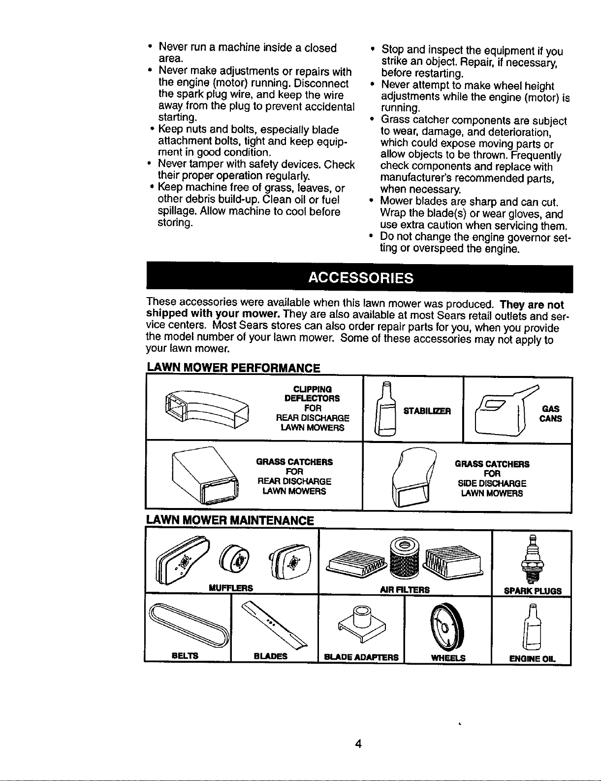
These accessories were available when this lawn mower was produced. They are not
shipped with your mower. They are also available at most Sears retail outlets and ser-
vice centers. Most Sears stores can also order repair parts for you, when you provide
the model number of your lawn mower. Some of these accessories may not apply to
your lawn mower.
LAWN MOWER PERFORMANCE
CLIPPING
DEFLECTORS
FOR
REAR DISCHARGE
LAWN MOWERS
GRASS CATCHERS
FOR
REAR DISCHARGE
I.AWN MOWERS
STABILIZER
GRASSCATCHERS
FOR
I SIDEDISCHARGE
LAWNMOWERS
LAWN MOWER MAINTENANCE
MUFFLERS
BLADES
AIR RLTERS
U_.OE AOAP'rERS _n.4_-_
SPARK PLUGS
ENGINEOIL
4
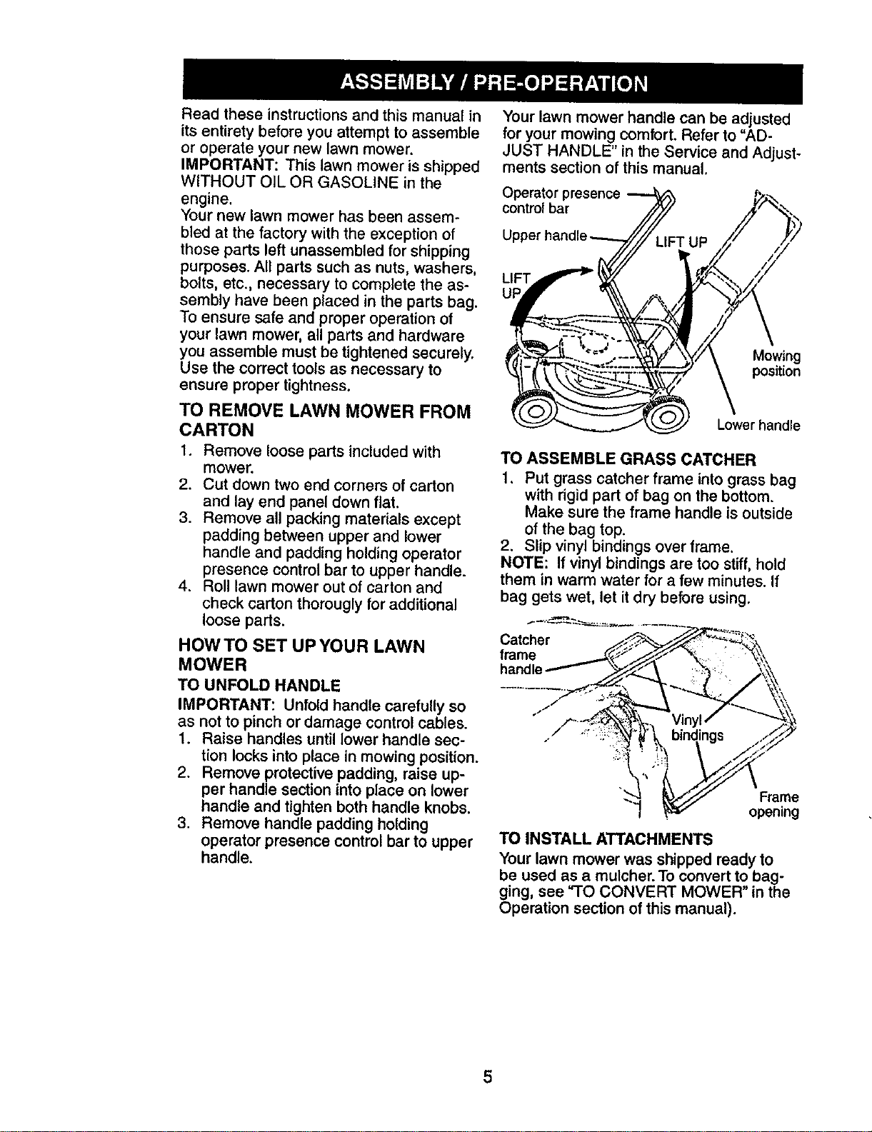
Read these instructions and this manual in
its entirety before you attempt to assemble
or operate your new lawn mower.
IMPORTANT: This lawn mower is shipped
WITHOUT OiL OR GASOLINE in the
engine.
Your new lawn mower has been assem-
bled at the factory with the exception of
those parts left unassembled for shipping
purposes. All parts such as nuts, washers,
bolts, etc., necessary to complete the as-
sembly have been placed in the parts bag.
To ensure safe and proper operation of
your lawn mower, all parts and hardware
you assemble must be tightened securely.
Use the correct tools as necessary to
ensure proper tightness.
TO REMOVE LAWN MOWER FROM
CARTON
1. Remove loose parts included with
mower.
2. Cut down two end corners of carton
and lay end panel down flat.
3. Remove all packing materials except
padding between upper and lower
handle and padding holding operator
presence control bar to upper handle.
4. Roll lawn mower out of carton and
check carton thorougly for additional
loose parts.
HOW TO SET UP YOUR LAWN
MOWER
TO UNFOLD HANDLE
IMPORTANT: Unfold handle carefully so
as not to pinch or damage control cables.
1. Raise handles until lower handle sec-
tion locks into place in mowing position.
2. Remove protective padding, raise up-
per handle section into place on lower
handle and tighten both handle knobs.
3. Remove handle padding holding
operator presence control bar to upper
handle.
Your lawn mower handle can be adjusted
for your mowing comfort. Refer to "AD-
JUST HANDLE" in the Service and Adjust-
ments section of this manual.
Operator presence
control bar
LIFT
UI
Mowing
position
Lower handle
TO ASSEMBLE GRASS CATCHER
1, Put grass catcher frame into grass bag
with rigid part of bag on the bottom.
Make sure the frame handle is outside
of the bag top.
2. Slip vinyl bindings over frame.
NOTE: If vinyl bindings are too stiff, hold
them in warm water for a few minutes. If
bag gets wet, let it dry before using.
Catcher
frame
handle
Frame
opening
TO INSTALL ATTACHMENTS
Your lawn mower was shipped ready to
be used as a mulcher. To convert to bag-
ging, see "TO CONVERT MOWER" in the
Operation section of this manual).
5
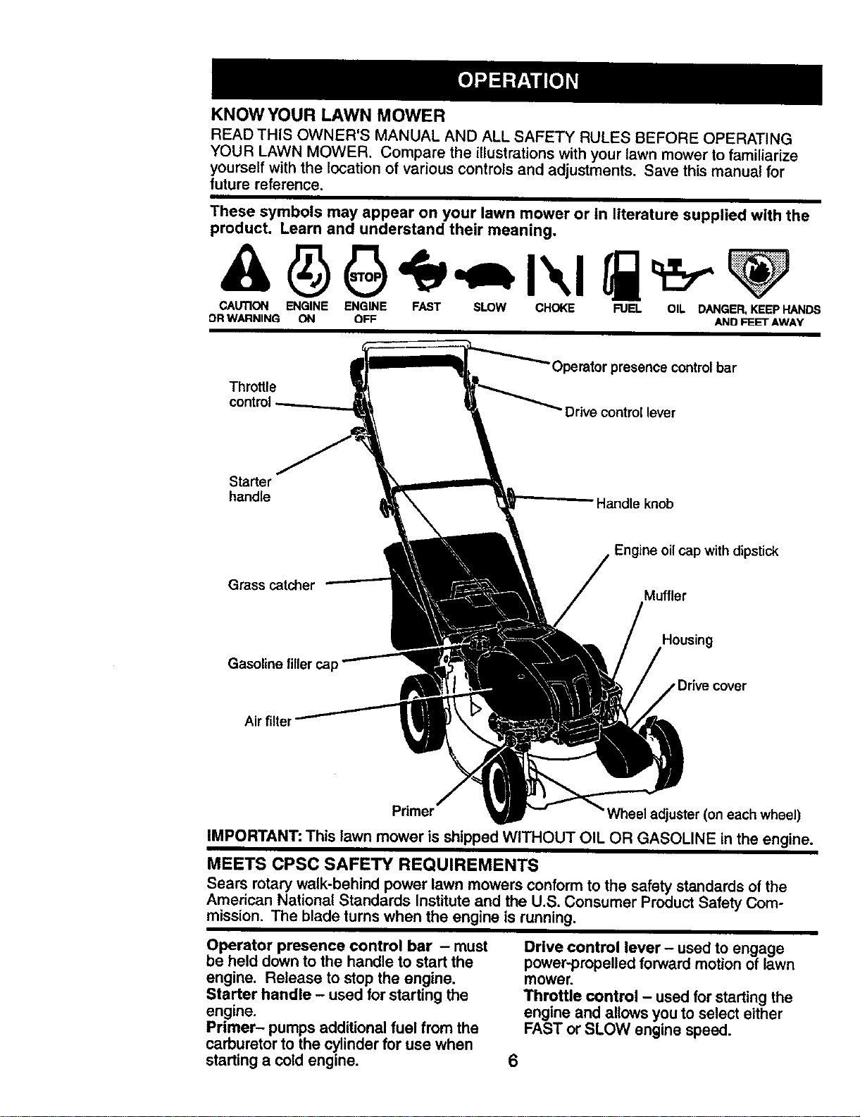
KNOW YOUR LAWN MOWER
READTHISOWNER'S MANUALAND ALL SAFETY RULES BEFOREOPERATING
YOUR LAWN MOWER. Compare the illustrations with your lawn mower to familiarize
yourself with the location of various controls and adjustments. Save this manual for
future reference.
These symbols may appear on your lawn mower or in literature supplied with the
product. Learn and understand their meaning.
CAUTION ENGINE ENGINE FAST SLOW CHOKE FUEL OIL DANGER,KEEPHANDS
OR WARNING ON OFF AND FI_E'r AWAY
Throttle
Operator presence controlbar
Drive control lever
Starter
handle
Grass catcher
Engine oilcap with dipstick
Muffler
Gasoline filler cap
Housing
Air filter
Primer eeladjuster(oneachwheel)
IMPORTANT: This lawn mower is shipped WITHOUT OIL OR GASOLINE in the engine.
MEETS CPSC SAFETY REQUIREMENTS
Sears rotary walk-behind power lawn mowers conformto the safety standards of the
American National Standards Institute and the U.S. Consumer Product Safety Com-
mission. The blade turns when the engine is running.
Operator presence control bar - must
be held down to the handle to start the
engine. Release to stop the engine.
Starter handle - used for starting the
engine.
Primer- pumps additional fuel from the
carburetor to the cylinder for use when
starting a cold engine.
6
Drive control lever - used to engage
power-propelled forward motion of lawn
mower.
Throttle control - used for starting the
engine and allows you to select either
FAST or SLOW engine speed.
The operation of any lawn
mower can result in foreign
objects thrown into the
eyes, which can result in
severe eye damage.
Always wear safety glasses or eye shields
while operating your lawn mower or
performing any adjustments or repairs.
We recommend standard safety glasses
or a wide vision safety mask worn over
spectacles.
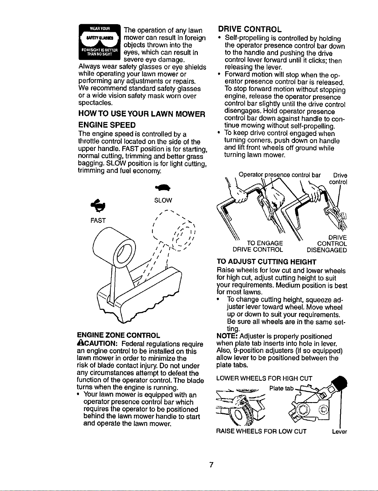
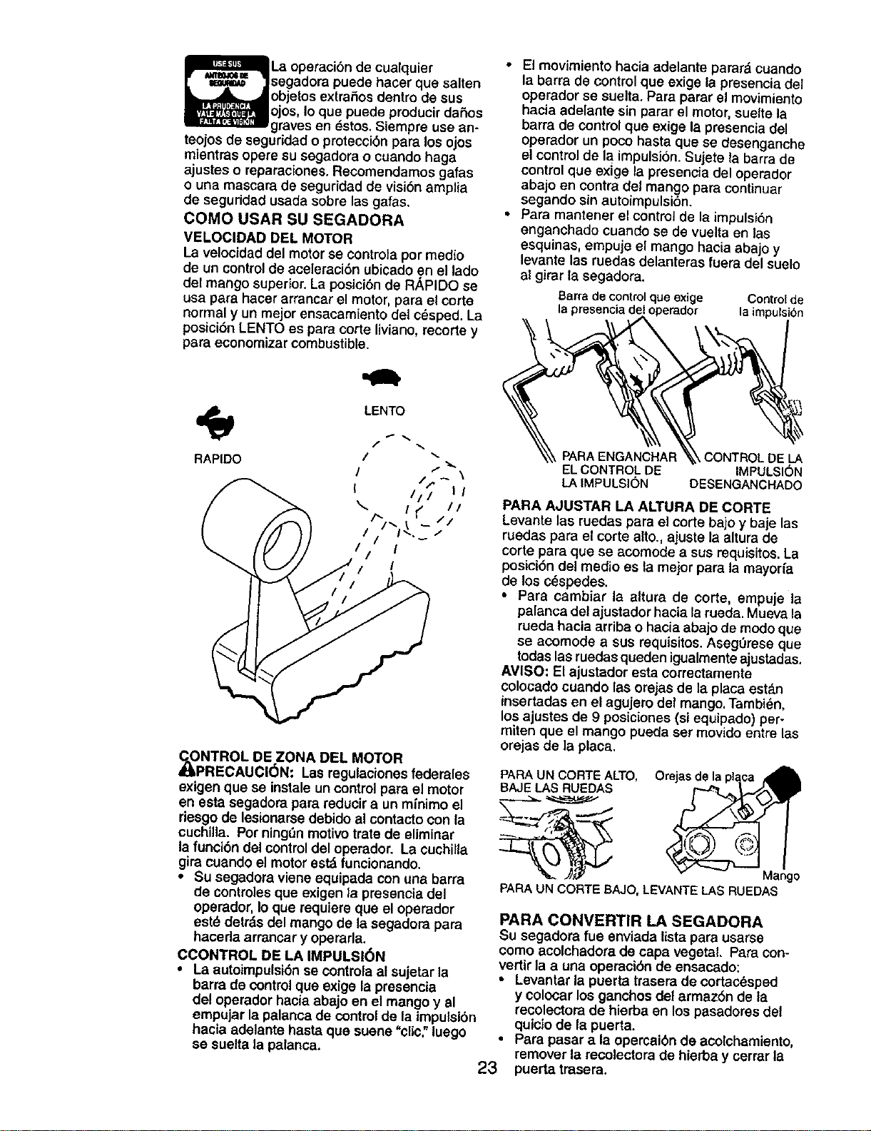
HOWTO USEYOUR LAWN MOWER
ENGINE SPEED
The engine speed is controlled by a
throttle control located on the side of the
upper handle. FAST position is for starting,
normal cutting, trimming and better grass
bagging. SLOW position is for light cutting,
trimming and fuel economy.
SLOW
FAST
ENGINE ZONE CONTROL
_LCAUTION: Federal regulations require
an engine control to be installed on this
lawn mower in order to minimize the
risk of blade contact injury. Do not under
any circumstances attempt to defeat the
function of the operator control. The blade
turns when the engine is running.
• Your lawn mower is equipped with an
operator presence control bar which
requires the operator to be positioned
behind the lawn mower handle to start
and operate the lawn mower.
DRIVE CONTROL
• Self-propelling is controlled by holding
the operator presence control bar down
to the handle and pushing the drive
control lever forward until it clicks;then
releasing the lever.
• Forward motion willstop when the op-
erator presence control bar is released.
To stop forward motion without stopping
engine, release the operator presence
control bar slightly until the drive control
disengages. Hold operator presence
control bar down against handle to con-
tinue mowing without self-propelling.
• To keep drive control engaged when
turning corners, push down on handle
and lift front wheels off ground while
turning lawn mower.
Operator presence control bar Drive
\ " -\_ _ "\ _Control
DRIVE
TO ENGAGE CONTROL
DRIVE CONTROL DISENGAGED
TO ADJUST CUTTING HEIGHT
Raise wheels for low cut and lower wheels
for high cut, adjust cutting height to suit
your requirements. Medium position is best
for most lawns.
• To change cutting height, squeeze ad-
juster lever toward wheel. Move wheel
up or down to suit your requirements.
Be sure all wheels are in the same set-
ting.
NOTE: Adjuster is properly positioned
when plate tab inserts into hole in lever.
Also, 9-position adjusters (if so equipped)
allow lever to be positioned between the
plate tabs.
LOWER WHEELS FOR HIGH CUT
Plate tal
RAISE WHEELS FOR LOW CUT Lever
7
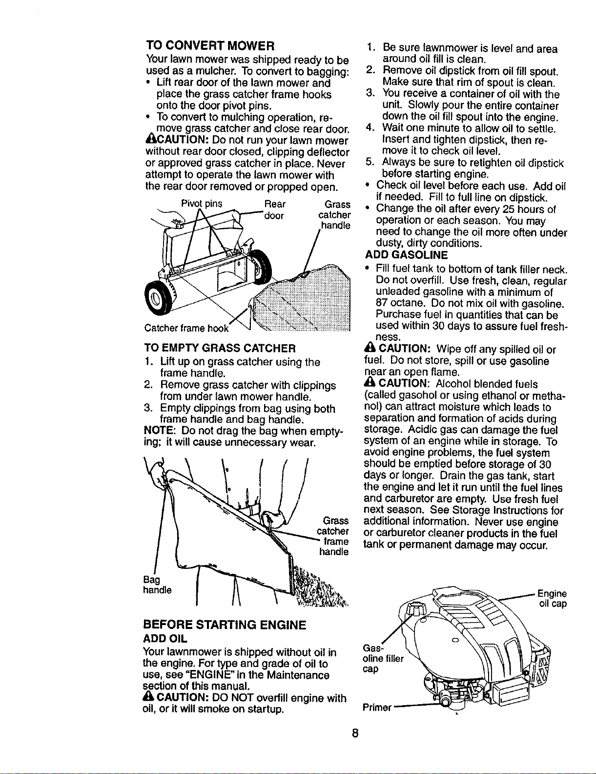
TO CONVERT MOWER
Yourlawn mower was shipped ready to be
used as a mulcher. To convert to bagging:
• Lift rear door of the lawn mower and
place the grass catcher frame hooks
onto the door pivot pins.
• To convert to mulching operation, re-
move grass catcher and close rear door.
_'_CAUTION: Do not run your lawn mower
without rear door closed, clipping deflector
or approved grass catcher in place. Never
attempt to operate the lawn mower with
the rear door removed or propped open.
Pivot " Rear Grass
catcher
handle
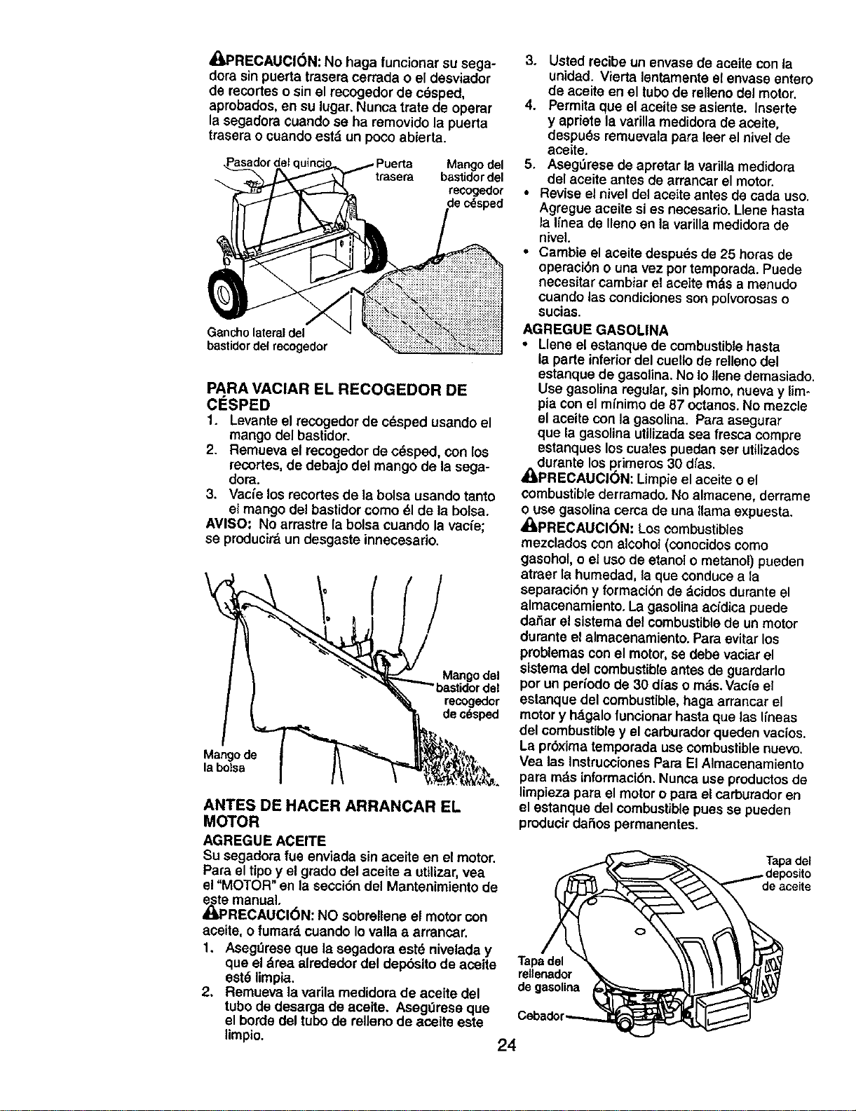
TO EMPTY GRASS CATCHER
1. Lift up on grass catcher using the
frame handle.
2. Remove grass catcher with clippings
from under lawn mower handle.
3. Empty clippings from bag using both
frame handle and bag handle.
NOTE: Do not drag the bag when empty-
ing; it will cause unnecessary wear.
Grass
catcher
frame
handle
1. Be sure lawnmower is level and area
around oil fill is clean.
2. Remove oil dipstickfrom oil fill spout.
Make sure that rim of spout is clean.
3. You receive a container of oil with the
unit. Slowly pour the entire container
down the oil fill spout into the engine.
4. Wait one minute to allow oil to settle.
Insert and tighten dipstick, then re-
move it to check oil level.
5. Always be sure to retighten oil dipstick
before starting engine.
• Check oil level before each use. Add oil
if needed. Fill to full line on dipstick.
• Change the oil after every 25 hours of
operation or each season. You may
need to change the oil more often under
dusty, dirty conditions.
ADD GASOLINE
• Fill fuel tank to bottom of tank filler neck.
Do not overfill. Use fresh, clean, regular
unleaded gasoline with a minimum of
87 octane. Do not mix oil with gasoline.
Purchase fuel in quantities that can be
used within 30 days to assure fuel fresh-
hess.
• kCAUTION: Wipe off any spilled oil or
fuel. Do not store, spill or use gasoline
,_ar an open flame.
CAUTION: Alcohol blended fuels
(called gasohol or using ethanol or metha-
nol) can attract moisture which leads to
separation and formation of acids during
storage. Acidic gas can damage the fuel
system of an engine while in storage. To
avoid engine problems, the fuel system
should be emptied before storage of 30
days or longer. Drain the gas tank, start
the engine and let it run until the fuel lines
and carburetor are empty. Use fresh fuel
next season. See Storage Instructionsfor
additional information. Never use engine
or carburetor cleaner products in the fuel
tank or permanent damage may occur.
Bag
handle
BEFORE STARTING ENGINE
ADD OIL
Your lawnmower is shipped without oil in
the engine. For type and grade of oil to oline filler
use, see "ENGINE" in the Maintenance cap
section of this manual.
CAUTION; DO NOT overfill engine with
oil, or it will smoke on startup. Primer
oilcap
8
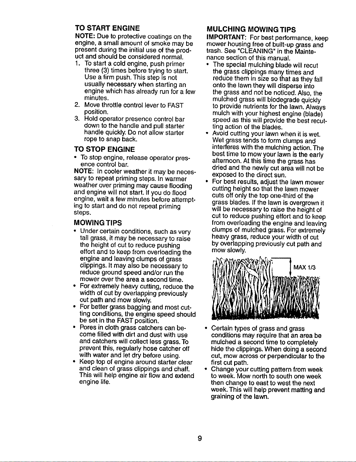
TO START ENGINE
NOTE: Due to protective coatings on the
engine, a small amount of smoke may be
present during the initial use of the prod-
uct and should be considered normal.
1. To start a cold engine, push primer
three (3) times before trying to start.
Use a firm push. This step is not
usually necessary when starting an
engine which has already run for a few
minutes.
2. Move throttle control lever to FAST
position.
3. Hold operator presence control bar
down to the handle and pull starter
handle quickly. Do not allow starter
rope to snap back.
TO STOP ENGINE
• To stop engine, release operator pres-
ence control bar.
NOTE: In cooler weather it may be neces-
sary to repeat priming steps. In warmer
weather over priming may cause flooding
and engine will not start. If you do flood
engine, wait a few minutes before attempt-
ing to start and do not repeat priming
steps.
MOWING TIPS
• Under certain conditions, such as very
tall grass, it may be necessary to raise
the height of cut to reduce pushing
effort and to keep from overloading the
engine and leaving clumps of grass
clippings. It may also be necessary to
reduce ground speed and/or run the
mower over the area a second time.
• For extremely heavy cutting, reduce the
width of cut by overlapping previously
cut path and mow slowly.
• For better grass bagging and most cut-
ting conditions, the engine speed should
be set in the FAST position.
• Pores in cloth grass catchers can be-
come filled with dirt and dust with use
and catchers will collect less grass. To
prevent this, regularly hose catcher off
with water and let dry before using.
• Keep top of engine around starter clear
and clean of grass clippings and chaff.
This will help engine air flow and extend
engine life.
MULCHING MOWINGTIPS
IMPORTANT: For best performance, keep
mower housing free of built-up grass and
trash. See "CLEANING" in the Mainte-
nance section of this manual.
• The special mulching blade will recut
the grass clippings many times and
reduce them in sJze so that as they fall
onto the lawn they will disperse into
the grass and not be noticed. Also, the
mulched grass will biodegrade quickly
to provide nutrients for the lawn. Always
mulch with your highest engine (blade)
speed as this will provide the best recut-
ting action of the blades.
• Avoid cutting your lawn when it is wet.
Wet grass tends to form clumps and
interferes with the mulching action. The
best time to mow your lawn is the early
afternoon. At this time the grass has
dried and the newly cut area will not be
exposed to the direct sun.
• For best results, adjust the lawn mower
cutting height so that the lawn mower
cuts off only the top one-third ofthe
grass blades. If the lawn is overgrown it
will be necessary to raise the height of
cut to reduce pushing effort and to keep
from overloading the engine and leaving
clumps of mulched grass. For extremely
heavy grass, reduce your width of cut
by overlapping previously cut path and
mow slowly.
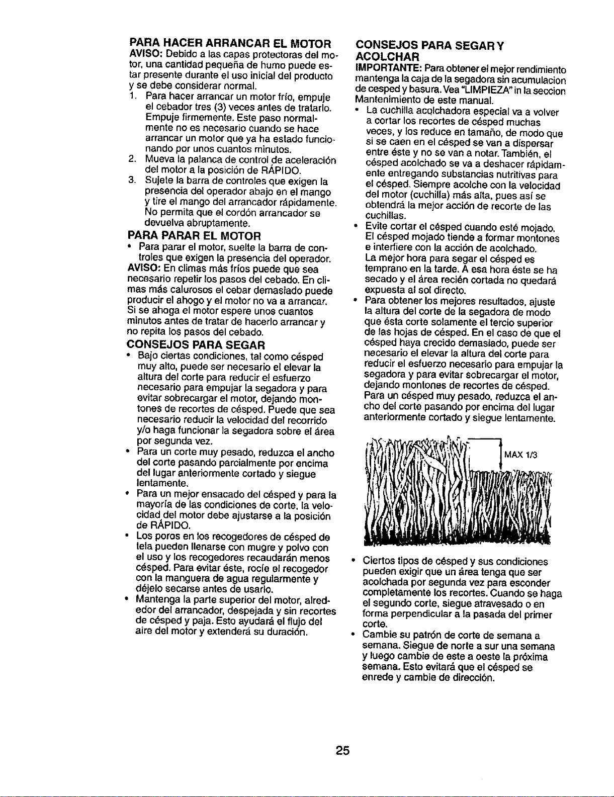
MAX 1/3
Certain types of grass and grass
conditions may require that an area be
mulched a second time to completely
hide the clippings. When doing a second
cut, mow across or perpendicular to the
first cut path.
Change your cutting pattern from week
to week. Mow north to south one week
then change to east to west the next
week. This will help prevent matting and
graining of the lawn.
9
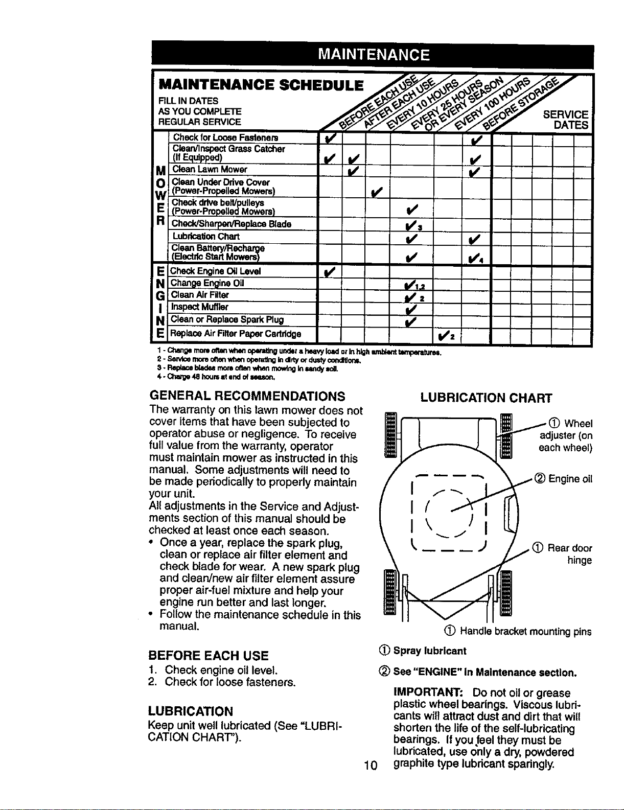
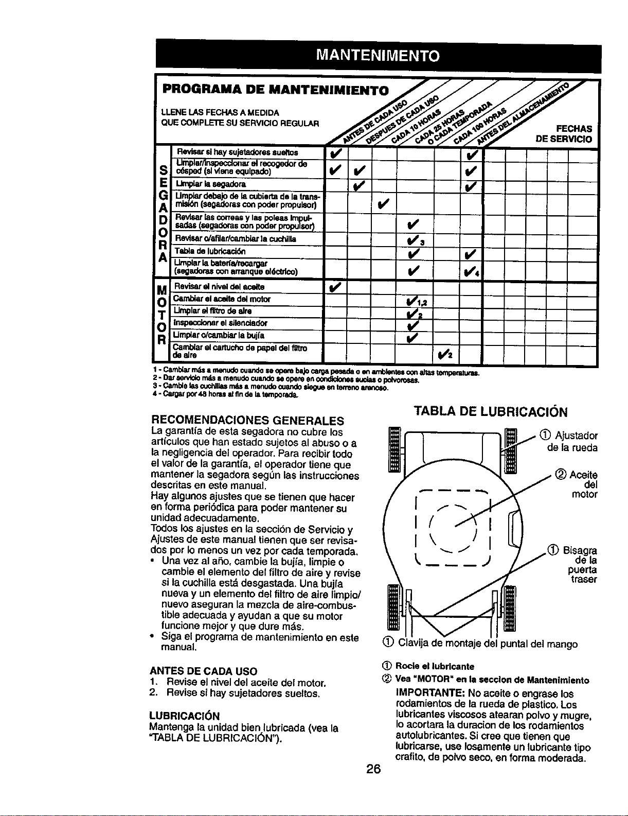
MAINTENANCE SCHEDULE/__o_._:o__o_y
FILL 'N DATES _ __'_€_-_'_*_'s_-_"_O_
,BYou
CheckforLooseFastanem II/'
Clean/InspectGrassCatcher
M CleanLavmMower
_N CleanUnderDriveCover
(Power-Propelled Mowers) ¥1
Check drive belt/pulleys ql_
E {Power.Propailed Mowers)
ChecldSharpan/Replece Blade _t_=l
LubricationChart I_
Clean Battery/Recharge
IElectdc Start iowers_) 1/ I/4
E Check Engine Oil Level 1/
Change EngineOil 1/iJ
G Clean Air Filter II/=
I InspectMuffler l/
N Clean or Replace Spark Plug
i/
ReplaceAir Filter Paper Cadddge 1/=
1- Cl_nOe rnomoftenwh4mop_ undota he_wyIoKi orInhighwnbkmt_oeratureB,
2- 8awl_ernoreo_m whenof_m_ng indrty ordusty¢ondltlotm.
3. Replaceblade_mornOf_l wlmnmowtng_ _mdy loll,
4. Gha_e 48 hou_ _ =ml of =NJIo_,
GENERAL RECOMMENDATIONS
The warranty on this lawn mower does not
cover items that have been subjected to
operator abuse or negligence. To receive
full value from the warranty, operator
must maintain mower as instructed in this
manual. Some adjustments will need to
be made periodically to properly maintain
your unit.
All adjustments in the Service and Adjust-
ments section of this manual should be
checked at least once each season.
• Once a year, replace the spark plug,
clean or replace air filter element and
check blade for wear. A new spark plug
and clean/new air filter element assure
proper air-fuel mixture and help your
engine run better and last longer.
• Follow the maintenance schedule in this
manual.
BEFORE EACH USE
1. Check engine oil level.
2. Check for loose fasteners.
LUBRICATION
Keep unit well lubricated (See "LUBRI-
CATION CHART").
LUBRICATION CHART
Wheel
adjuster (on
each wheel)
Engine oil
Rear door
hinge
(_) Handle bracket mounting pins
(_) Spray lubricant
(_) See "ENGINE" in Maintenance section.
10
IMPORTANT: Do not oil or grease
plastic wheel bearings. Viscous lubd-
cants will attract dust and dirt that will
shorten the life of the self-lubricating
bearings. If you.feel they must be
lubricated, use only a dry, powdered
graphite type lubricant sparingly.
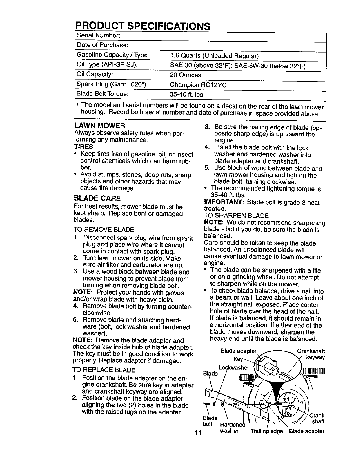
PRODUCT SPECIFICATIONS
Serial Number:
Date of Purchase:
Gasoline Capacity / Type: 1.6 Quarts (Unleaded Regular)
Oil Type (API-SF-SJ): SAE 30 (above 32°F); SAE 5W-30 (below 32°F)
Oil Capacity: 20 Ounces
Spark Plug (Gap: .020") Champion RC12YC
Blade Bolt Torque: 35-40 ft. Ibs.
The model and serial numbers will be found on a decal on the rear of the lawn mower
housing. Record both serial number and date of purchase in space provided above.
LAWN MOWER
Always observe safety rules when per-
forming any maintenance.
TIRES
• Keep tires free of gasotine, oil, or insect
control chemicals which can harm rub-
ber.
• Avoid stumps, stones, deep ruts, sharp
objects and other hazards that may
cause tire damage.
BLADE CARE
For best results, mower blade must be
kept sharp. Replace bent or damaged
blades.
TO REMOVE BLADE
1. Disconnect spark plug wire trom spark
plug and place wire where it cannot
come in contact with spark plug.
2. Turn lawn mower on its side. Make
sure air filter and carburetor are up.
3. Use a wood block between blade and
mower housing to prevent blade from
turning when removing blade bolt.
NOTE: Protect your hands with gloves
and/or wrap blade with heavy cloth.
4. Remove blade bolt by turning counter-
clockwise.
5. Remove blade and attaching hard-
ware (bolt, lock washer and hardened
washer).
NOTE: Remove the blade adapter and
check the key inside hub of blade adapter.
The key must be in good condition to work
properly. Replace adapter if damaged.
TO REPLACE BLADE
1. Position the blade adapter on the en-
gine crankshafL Be sure key in adapter
and crankshaft keyway are aligned.
2. Position blade on the blade adapter
aligning the two (2) holes in the blade
with the raised lugs on the adapter.
3. Be sure the trailing edge of blade (op-
posite sharp edge) is up toward the
engine.
4. Install the blade bolt with the lock
washer and hardened washer into
blade adapter and crankshaft.
5. Use block of wood between blade and
lawn mower housing and tighten the
blade bolt, turning clockwise.
• The recommended tightening torque is
35-40 ft. Ibs.
IMPORTANT: Blade bolt is grade 8 heat
treated.
TO SHARPEN BLADE
NOTE: We do not recommend sharpening
blade - but if you do, be sure the blade is
balanced.
Care should be taken to keep the blade
balanced. An unbalanced blade will
cause eventual damage to lawn mower or
engine.
• The blade can be sharpened with a file
or on a grinding wheel. Do not attempt
to sharpen while on the mower.
• To check blade balance, ddve a nail into
a beam or wall. Leave about one inch of
the straight nail exposed. Place center
hole of blade over the head of the nail.
If blade is balanced, it should remain in
a horizontal position. If either end of the
blade moves downward, sharpen the
heavy end until the blade is balanced.
Blade adapter, _ Crankshaft
k°yway
B,ade Lo_kwas_=rr__. _ /
H-'rdo,',e \ " -r' shatt
1 1 washer Trailir Iedge Blade adapter
GRASS CATCHER
• The grass catcher may be hosed with
water, but must be dry when used.
• Check your grass catcher often for dam-
age or deterioration. Through normal
use itwill wear. If catcher needs replac-
ing, replace only with a manufacturer
approved replacement catcher. Give the
lawn mower model number when order-
ing.
DRIVE WHEELS
Check front drive wheels each time before
you mow to be sure they move freely.
The wheels notturning freely means
trash, grass cuttings, etc. are in the drive
wheel area and must be cleaned to free
drive wheels.
If necessary to clean the drive wheels, be
sure to clean both front wheels.
1. Remove hubcaps, hairpin cotters and
washers.
2. Remove wheels from wheel adjusters.
3. Remove any trash or grass cuttings
from inside the dust cover, pinion and/
or drive wheel gear teeth.
4. Put wheels back in place.
NOTE: If after cleaning, the drive wheels
do not turn freely, contact a Sears or other
qualified service center.
GEAR CASE
• To keep your drive system working
properly,the gear case and area around
the drive should be kept clean and free
of trash build-up. Clean under the drive
cover twice a season.
• The gear case is filled with lubricant to
the proper levelat the factory. The only
time the lubricant needs attention is if
service has been performed on the gear
case.
• If lubricant is required, use only Elf
brand oil, Part No. REDUCTELF 100.
Do not substitute.
ENGINE
LUBRICATION
Use only high quality detergent oil rated
with API service classification SF-SJ. Se-
lect the oil's SAE viscosity grade accord-
ing to your expected operating tempera-
tura.
8AE V15C061"_ GRADES
m
'1_ _ cp Iop I_* _ _ _ 10_'
W,_ATURE RANGI__ATED _ NEXT01. _A/_QE
NOTE: Although multi-viscosity oils
(5W30, 10W30 etc.) improve starting in
cold weather, these multi-viscosityoils will
result in increased oil consumption when
used above 32°F. Check your engine oil
level more frequently to avoid possible
engine damage from running low on oil.
Change the oil after every 25 hours of
operation or at least once a year if the
lawn mower is not used for 25 hours in
one year.
Check the crankcase oil level before start-
ing the engine and after each five (5)
hours of continuous use. Tighten oil plug
securely each time you check the oil level.
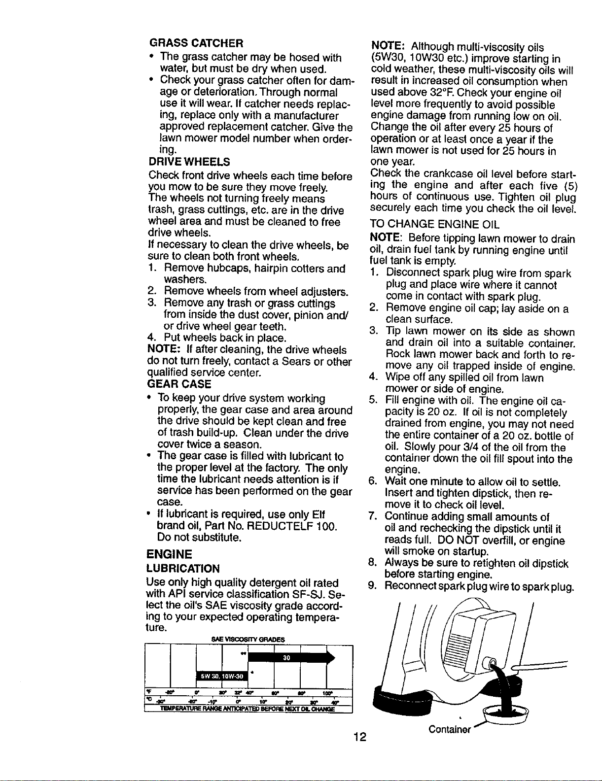
TO CHANGE ENGINE OIL
NOTE: Before tipping lawn mower to drain
oil, drain fuel tank by running engine until
fuel tank isempty.
1. Disconnect spark plug wire from spark
plug and place wire where itcannot
come in contact with spark plug.
2. Remove engine oil cap; lay aside on a
clean surface.
3. Tip lawn mower on its side as shown
and drain oil into a suitable container.
Rock lawn mower back and forth to re-
move any oil trapped inside of engine.
4. Wipe off any spilled oil from lawn
mower or side of engine.
5. Fillengine with oil. The engine oil ca-
pacity is 20 oz. Ifoil is not completely
drained from engine, you may not need
the entire container of a 20 oz. bottle of
oil. Slowly pour 3/4 of the oil from the
container down the oil fill spout intothe
engine.
6. Wait one minute to allow oil to settle.
Insert and tighten dipstick, then re-
move it to check oil level.
7. Continue adding small amounts of
oiland rechecking the dipstick untilit
reads full. DO NOT overfill,or engine
will smoke on startup.
8. Always be sure to retighten oil dipstick
before starting engine.
9. Reconnect spark plug wire tospark plug.
Container
12

AIR FILTER
Your engine will not run properly using a
dirty air filter. Clean the foam pre-cleaner
after every 25 hours of operation or every
season. Replace paper cartridge every
100 hours of operation or every season,
whichever occurs first. Service air cleaner
more often under dusty conditions.
1. Loosen screws and remove cover.
2. Carefully remove cartridge.
3. Clean by gently tapping on a flat sur-
face. If very dirty, replace cartridge.
_CAUTION: Petroleum solvents, such as
kerosene, are not to be used to clean car-
tridge. They may cause deterioration of the
cartridge. Do not oil cartridge. Do not use
pressurized air to clean or dry cartridge.
4. Install cartridge, then replace cover.
Base
MUFFLER
Inspect and replace corroded muffler as it
could create a fire hazard and/or damage.
SPARK PLUG
Replace spark plug at the beginning of
each mowing season or after every 100
hours of operation, whichever occurs
first. Spark plug type and gap setting are
shown in "PRODUCT SPECIFICATIONS"
in Maintenance section of this manual.
CLEANING
IMPORTANT: For best performance, keep
mower housing free of built-up grass and
trash. Clean the underside of your mower
after each use.
_CAUTION: Disconnect spark plug wire
from spark plug and place wire where it
cannot come in contact with the spark
plug.
• Clean the underside of your lawn mower
by scraping to remove build-up of grass
and trash.
• Clean engine often to keep trash from
accumulating. A clogged engine runs
hotter and shortens engine life.
• Keep finished surfaces and wheels free
of all gasoline, oil, etc.
• We do not recommend using a garden
hose to clean lawn mower unless the
electrical system, muffler, air filter and
carburetor are covered to keep water
out. Water in engine can result in short-
ened engine life.
CLEAN UNDER DRIVE COVER
Clean under drive cover at least twice a
season. Scrape underside of cover with
putty knife or similar tool to remove any
build-up of trash or grass on underside of
drive cover.
_I_,WARNING: To avoid serious injury,
before performing any service or adjust-
ments:
1. Release control bar and stop engine.
2. Make sure the blade and all moving
parts have completely stopped.
3. Disconnect spark plug wire from spark
plug and place where it cannot come in
contact with plug.
LAWN MOWER
TO ADJUST CUTTING HEIGHT
See "TO ADJUST CUTTING HEIGHT" in
the Operation section of this manual.
REAR DEFLECTOR
The rear deflector, attached between the
rear wheels of your mower, is provided to
minimize the possibility that objects will
be thrown out of the rear of the mower
into the operator's mowing position. If the
deflector becomes damaged, it should be
replaced.
13
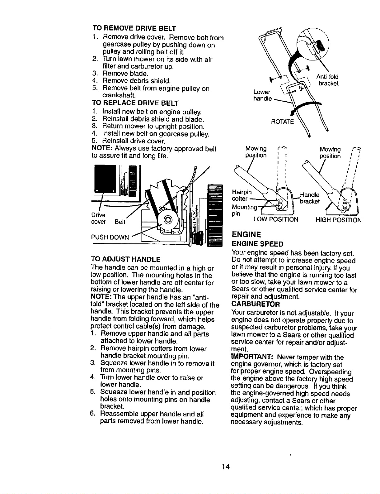
TO REMOVE DRIVE BELT
1. Remove drive cover. Remove belt from
gearcase pulley by pushing down on
pulley and rolling belt off it.
2. Turn lawn mower on its side with air
filter and carburetor up.
3. Remove blade.
4. Remove debris shield.
5. Remove belt from engine pulley on
crankshaft.
TO REPLACE DRIVE BELT
1. Install new belt on engine pulley.
2. Reinstall debris shield and blade.
3. Return mower to upright position.
4. Install new belt on gearcase pulley,
5. Reinstall drive cover.
NOTE: Always use factory approved belt
to assure fit and long life.
Drive
cover Belt
TO ADJUST HANDLE
The handle can be mounted in a high or
low position. The mounting holes in the
bottom of lower handle are off center for
raising or lowering the handle.
NOTE: The upper handle has an "anti-
fold" bracket located on the left side of the
handle. This bracket prevents the upper
handle from folding forward, which helps
protect control cable(s) from damage.
1. Remove upper handle and all parts
attached to lower handle.
2. Remove hairpin cotters from lower
handle bracket mounting pin.
3. Squeeze lower handle in to remove it
from mounting pins.
4, Turn lower handle over to raise or
lower handle.
5. Squeeze lower handle in and position
holes onto mounting pins on handle
bracket.
6. Reassemble upper handle and all
parts removed from lower handle.
Anti-fold
bracket
Lower
ROTATE
Mowing
Hairpin
pin
LOW POSITION
ENGINE
ENGINE SPEED
Your engine speed has been factory set,
Do not attempt to increase engine speed
or it may result in personal injury. If you
believe that the engine is running too fast
or too slow, take your lawn mower to a
Sears or other qualified service center for
repair and adjustment.
CARBURETOR
Yourcarburetor is not adjustable. If your
engine does not operate properly due to
suspected carburetor problems, take your
lawn mower to a Sears or other qualified
service center for repair and/or adjust-
ment.
IMPORTANT: Never tamper withthe
engine governor, which is factory set
for proper engine speed. Overspeeding
the engine above the factory high speed
setting can be dangerous. Ifyou think
the engine-governed high speed needs
adjusting, contact a Sears or other
qualified service center, which has proper
equipment and experience to make any
necessary adjustments.
14
Immediately prepare your lawn mower for
storage at the end of the season or if the
unit will not be used for 30 days or more.
LAWN MOWER
When lawn mower is to be stored for a pe-
riod of time, clean it thoroughly, remove all
dirt, grease, leaves, etc. Store in a clean,
dry area.
1. Clean entire lawn mower (See
"CLEANING" in the Maintenance sec-
tion of this manual).
2. Lubricate as shown in the Maintenance
section of this manual.
3. Be sure that all nuts, bolts, screws,
and pins are securely fastened. Inspect
moving parts for damage, breakage
and wear. Replace if necessary.
4. Touch up a_lrusted or chipped paint
surfaces; sand lightly before painting.
HANDLE
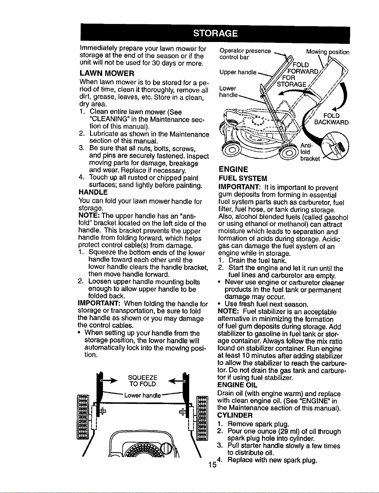
You can fold your lawn mower handle for
storage.
NOTE: The upper handle has an "anti-
fold" bracket located on the left side of the
handle. This bracket prevents the upper
handle from folding forward, which helps
protect control cable(s) from damage.
1. Squeeze the bottom ends of the lower
handle toward each other until the
lower handle clears the handle bracket,
then move handle forward.
2. Loosen upper handle mounting bolts
enough to allow upper handle to be
folded back.
IMPORTANT: When folding the handle for
storage or transportation, be sure to fold
the handle as shown or you may damage
the control cables.
• When setting up your handle from the
storage position, the lower handle will
automatically lock into the mowing posi-
tion.
SQUEEZE
TO FOLD
Operator presence
controlbar
Upper
Lower
handle_
FOLD
BACKWARD
bracket
ENGINE
FUEL SYSTEM
IMPORTANT: It is important to prevent
gum deposits from forming in essential
fuel system parts such as carburetor, fuel
filter, fuel hose, or tank during storage.
Also, alcohol blended fuels (called gasohol
or using ethanol or methanol) can attract
moisture which leads to separation and
formation of acids during storage. Acidic
gas can damage the fuel system of an
engine while in storage.
1. Drain the fuel tank.
2. Start the engine and let it run untilthe
fuel lines and carburetor are empty.
• Never use engine or carburetor cleaner
products in the fuel tank or permanent
damage may occur.
• Use fresh fuel next season.
NOTE: Fuel stabilizer is an acceptable
alternative in minimizing the formation
of fuel gum deposits during storage. Add
stabilizer to gasoline in fuel tank or stor-
age container. Always follow the mix ratio
found on stabilizer container. Run engine
at least 10 minutes after adding stabilizer
to allow the stabilizer to reach the carbure-
tor. Do not drain the gas tank and carbure-
tor if using fuel stabilizer.
ENGINE OIL
Drain oil (with engine warm) and replace
with clean engine oil. (See "ENGINE" in
the Maintenance section of this manual).
CYLINDER
1. Remove spark plug.
2. Pour one ounce (29 ml) of oil through
spark plug hole into cylinder.
3. Put1starter handle slowly a few times
to distribute oil.
54. Replace with new spark plug.
1
OTHER
• Do not store gasoline from one season
to another.
• Replace your gasoline can if your can
starts to rust. Rust and/or dirt in your
gasoline will cause problems.
• If possible, store your unit indoors and
cover it to protect it from dust and dirt.
° Cover your unit with a suitable protective
cover that does not retain moisture. Do
not use plastic. Plastic cannot breathe,
which allows condensation to form and
will cause your unit to rust.
IMPORTANT: Never cover mower while
_gine and exhaust areas are still warm.
CAUTION: Never store the lawn mower
with gasoline in the tank inside a building
where fumes may reach an open flame or
spark. Allow the engine to cool before stor-
ing in any enclosure.
TROUBLESHOOTING - See appropriate section in manual unless directed
to a Sears Service Center.
PROBLEM CAUSE CORRECTION
Does not start 1. Dirty air filter. 1. Clean/replace air filter.
2. Out of fuel.
3, Stale fuel.
4. Water in fuel.
5. Spark plug wire is
disconnected.
6. Bad spark plug.
7. Loose blade or broken
blade adapter.
8. Control bar in released
position.
9. Control bar defective.
10. Fuel valve lever (if so
equipped) in OFF position.
11.Weak battery (if equipped).
12.Disconnected battery
connector (if equipped).
2. Fill fuel tank.
3. Drain tank and refillwith
fresh, clean fuel.
4. Drain fuel tank and
carburetor and refill tank
with fresh gasoline.
5, Connect wire to plug.
6.
7.
Replace spark plug.
Tighten blade bolt or
replace blade adapter.
8. Depress control bar to
handle.
9. Replace control bar.
10.Turn fuel valve lever
to the ON position.
11.Charge battery.
12. Connect battery to engine.
16
TROUBLESHOOTING - See appropriate section in manual unless directed
to a Sears Service Center.
CAUSEPROBLEM
Loss of power
Poor cut -
uneven
Excessive
vibration
Starter rope
hard to pull
1, Rear of lawn mower
housing or cutting blade
dragging in heavy grass,
2, Cutting too much grass.
3, Dirty air filter.
4. Buildup of grass, leaves,
and trash under mower.
5. Too much oil in engine.
6, Walking speed too fast.
1. Worn, bent or loose blade.
2. Wheel heights uneven.
3. Buildup of grass, leaves
and trash under mower.
1. Worn, bent or loose blade.
2. Bent engine crankshaft.
2.
3.
4.
Engine flywheel brake is on
when control bar is released.
Bent engine crankshaft,
Blade adapter broken.
Blade dragging in grass.
CORRECTION
1, Set to"Higher Cut"
position.
2. Set to "Higher Cut"
position.
3. Clean/replace air filter.
4. Clean underside of mower
housing.
5. Check oil level.
6. Cut at slower walking speed.
1. Replace blade. Tighten
blade bolt.
2. Set all wheels at same
height.
3. Clean underside of
mower housing.
1. Replace blade. Tighten
blade bolt.
2. Contact a Sears or other
qualified service center.
1. Depress control bar to
upper handle before
pulling starter rope.
2. Contact a Sears or other
qualified service center.
3. Replace blade adapter.
4. Move lawn mower to cut
grass or to hard surface.
Grass catcher 1. Cutting height too low. 1. Raise cutting height.
not filling 2. Lifton blade worn off. 2. Replace blade.
(If so equipped) 3. Catcher not venting air. 3. Clean grass catcher.
Hard to push 1. Raise cutting height.
1, Grass is too high or wheel
height is too low.
2. Rear of lawn mower
housing or cutting blade
dragging in grass.
3. Grass catcher too full.
4. Handle height position not
right foryou.
Loss of drive
Ior slowing of
' drive speed
1. Belt wear.
2, Belt off of pulley.
3. Drive cable worn or broken.
4. Dirt in drive pinions.
2. Raise rear of lawn mower
housing one (1) setting
higher.
3. Empty grass catcher.
4. Adjust handle height to suit.
1. Check/replace drive belt.
2, Check/reinstall drive belt.
3. Replace drive cable.
4. Clean drive pinions.
17
Garantfa ......................................................... 18
Reglas de Seguridad ................................ 18-20
Montaje / Pre-Operacibn ............................... 21
Operaci6n ................................................. 22-25
Mantenimiento .......................................... 26*29
Programa de Mantenimiento ......................... 26
Especificaciones del Producto ....................... 27
Servicio y Adjustes ................................... 29-31
Almacenamiento ....................................... 31-32
Identificaci6n de problemas ...................... 32-33
Servicio Sears .......................................... 35-43
Orden de Partes ............................... Contratapa
GARANT[A LIMITADA DE DOS AI_IOS PARA LA SEGADORA A MOTOR CRAFTSMAN
For dos (2) aSos, a partir de la fecha de compra, cuando esta Segadora Craftsman se mantenga,
lubrique y aline seg_n _s instrucciones para la operacibn y el mantenimiento en el manual del
duefio, Sears reparard gratis todo defecto en el material y la mano de obra.
Si la Segadora Craftsman se usa pare fines comerciales o de arriendo, esta garantia s61ose aplica
por noventa (90) dfas a partir de la fecha de compra.
Esta Garantia no cubre:
• Artfculos que se desgastan durante el uso normal tales como las cuchillas segadoras rotatorias,
los adaptadores de la cuchllla, las correas, los filtros de aire y las buj_as.
• Reparaciones necesarias debido al abuso o ala negligencia del operador, incluy_ndose a los
cigQeSales dobladoe y ala falta de mantenimiento del equipo segOn las instrucciones que se
incluyenen el manual del dueho.
EL SERVICIO DE GARANT(A ESTA DISPONIBLE al devolver la segadora a motor Craftsman al
centro/departmento de servicio Sears mas cercano en los Estados Unidos. Esta garantia se apUca
solamente mientras el producto este en uso en los Estados Unidos.
Esta Garantfa le otorga derechos legales especfficos, y puede qua tambien tenga otros derechos
que varfan de estado a estado.
SEARS, ROEBUCK AND CO., D/817WA, HOFFMAN ESTATES, IL 60179 USA
IMPORTANTE: Esta maquina cortadaora es capaz de amputar las manos y los manos y los pies y
de lanzar objetos. Si no se observan lee instrucciones de seguridad siguientes se pueden producir
lesionas graves o la muerte.
_Busque este simbolo que setSala las precau-
clones de segurida.d de importancia. Quiere
decir- IIIATENClON!!!iiiESTE ALERTO!!! SU
SEGURIDAD ESTA
COMPROMETIDA.
_,DVERTENCIA: Siempre desconecte el
atambre de ta bujla y p6ngalo donda no pueda
entrar en contacto con la bujfa, para evitar el
arranque por accidente, durante la preparaci6n,
el transporte, el ajuste o cuando se hacen
reparaciones.
_s.DVERTENCIA: Los bornes, terminales y
acceeorioe relativos de la batert'a contienen
plomo o compuestos de plomo, productos
qufmicos conocidos en el Estado de California
como causa de cdncer y defeetos al nacimiento
uotros dafios reproductivos. Lavar las manos
despu6s de manipulerlos.
_PRECAUCI6N: El tubo de escape del motor,
algunos de sus constituyentesy algunos com-
ponentes del vehiculo contienen o desprenden
productosqufmicos conocidos en el Estado de
California come causa de c&ncery defectos al
nacimiento u otros dafios reproductivos.
_I=PRECAUCI(_N: El silenciadory otras
piezas del motor Uegan a sre extremadamente
calientes durante la operacidn y siguen siendo
ealientes despuds de qua el motor haya parado.
Para evitar quemaduras severas, permanezca
lejos de estas dreas.
18
I. OPERACION
• Antes de empezar, debe familiarizarse
completamente con los controlesy el use
correcto de la maquina. Para esto, debe leer
y comprender todas las instrucciones que
aparecen en la maquina y en los manuales
de operaci6n.
• No ponga las manes o toe pies oerca o
debajo de las partes rotatorias. Mant_ngase
siempre lejos de la abertura de la descarga.
• Permita que solamente las personas re-
sponsables que est_n familiarizadas con las
instruccionesoperen la mAquina.
• Despeje el _,reade objetos tales come pie-
dras, juguetes, alambres, huesos, palos, etc.
que pueden ser recog{dosy lanzados per las
cuchillas.
• Asegerese que el Area no se hallen per-
sonas, antes de segar. Pare la mAquina si
alguien entra en el Area.
• No opere la maqaina sin zapatos o con
sandalias abiertas. P6ngase siempre zapatos
s611dos.
• No tire de {a segadora hacia atr_s a menos
que sea absolutamente necesario. Mire
siempre hacia abajo y hacia detrAs antes y
mientras que se mueve hacia atr_s.
• No opera la segadora sin los respectivos
resguardos, las placas, el reCogeder de
c_sped u otros aditamentos dise ados para
su proteccion y seguridad.
Refi_rase alas instrucoionee del fabrieante
para el funcionamiento e instalaci6n de
accesorios. Use _nicamente accesorios apro-
bados per el fabricante.
• Detenga la cuchilla o las cuohillas cuando
cruce per calzadas, calles o caminos de
grava.
• Parar el motor cada vez que se abandona el
aparato, antes de limpiar la segadora o de
remover residues del tube.
• Apagar el motor y esperar hasta que las
cuchiltas est6n completamente paradas antes
de remover el receptor de hierba.
• Segar solamente con luz del dia o con una
buena luz artificial.
• No opera la mAquina bajo la influencia del
alcohol o de las drogas.
• Nunca opera la maquina cuando la hierba
est_ mojada. Aseg,',rese siempre de tenet
buena tracoi6n ensus pies; mantenga el
mango firmemente y camine; nunca corra.
• Desconectar el mecanismo de propulsi6n
autbnoma o el embrague de transmisi6n en
las segadoras que Io tienen antes de poner
en marcha el motor.
• Si el equipo empezara a vibrar de una
manera anormat, pare el motor y revise de
inmediato para averiguar la ¢ausa. General-
mente la vibraci6n suele indicar que existe
alguna averfa.
• Siempre use galas de seguddad o anteojos
con protecci6n lateral cuando opera la sega-
dora.
II. OPERACION SOBRE LAS CUESTAS
Los accidentes ocurren con md$ frecuencia en
las cuestas. Estos accidentes ocurren debido a
resbaladas o caldas, las cuales pueden resultar
en graves lesiones. Operar la recortadora en
cuestas requiere mayor concentraci6n. Si se
siente inseguro en una cuesta, no la recorte.
HACER:
• Puede recortar a trav_s de la superficie de
la cuesta, nunca hacia ardba y hacia abajo.
Proceda con extrema precauci6n cuando
cambie de direcci6n en las cuestas.
• Renueva redes los objetos extrafios, tales
come guijarros, ramas, etc.
• Debe preatar atenci6n a hoyos, baches o
protuberancias. Recuerde que la hierba alta
puede esconder obstdculos.
NO HACER:
• No recorte cerca de pendientes, zanjas o
terraplenes. El operador puede perder la
tracci6n en los pies o el equilibrio.
• No recorte cuestas demasiado inclinadas.
• No recorte en hierba mojada. La reducoi6n
en la tracci6n de la pisada puede causar
resbalones.
III. NII_IOS
Se pueden producir acoidentes trAgicos si el
operador no presta ateneibn a la presencia
de los nifios, A menudo, los nifios se sienten
atraidos per la mdquina y per la actividad de
la siega. Nunca suponga que los nifios van a
permanecer en el mismo lugar donde los vie
per m]ltimavez.
• Mantenga a los nifios alejados del Area de
la siega y bajo el cuidado estricto de otra
persona adu_ta responsab_e.
• Est6 alerta y apague la mAquina sihay nifios
que entran al Area.
• Antes y cuando este retrocodiendo, mire
hacia atrAs y hacia abajo para veriflcar si hay
nifios pequefios.
• Nunca permita que los nifios operen la md-
quina.
• Tenga un cuidado extra cuando se acerque
a esquinas donde no hay vislbilidad, a los
arbustos, _.rboles u otros objetos que pueden
interferir con su Ifnea de visi6n.
IV. SERVICIO
• Tenga cuidado extraal manejar la gasolina y
los demAs combustibles. Son inflamables y
los gases son explosives.
- Use soLamente un envase aprobado.
° Nunca remueva la tapa del depbsito de
gasolina o agregae combustible con el mo-
tor funcionando. Permita que el motor se
enfrie antes de velvet a pone combustible.
No fume.
Nunca vuelva a porter combustible en la
mdquina en recintos cerrados.
- Nunca almacene ta mdqulna o el envase
del combustible dentro de algdn lagar en
deride haya una llama expuesta, tal come
la del calentador de agua.
19
• Nunca haga funcionar una m&quina dentro
de un &tea cerrada.
• Nunca haga aiustes o reparaciones mientras
el motor est_ en marcha. Desconecte el
cable de la bujM, y mant_ngalo a cierta
distanda de _sta pare prevenir un arranque
accidental.
• Mantenga las tuercas y los pernos, espe-
cialmente los pemos del accesorio de ta
cuchilla, epretados y mantenga el equipo en
buenas condiciones.
• Nunca manipu}e de forma indebida los
dispositivos de seguridad. Controle regular-
mente su funcionamiento correcto.
• Mantenga la mfiquina libre de hierba, hojas
u otras acumulaciones de desperdicio.
Limpie los derrames de aceite o combustible.
Permita que la m&quina se entrie antes de
atmacenada.
• Pare e inspeccione el equipo si le pega a un
objeto. Rep&relo, si es necesario, antes de
hacado arranCaro
• En ningOncaso hay que regular la altura de
las ruedas mientras el motorest& en marcha.
• Los componentes del receptor de la hierba
van sujetos a desgaste, da£=osy deterioro,
que pueden exponer las partes en mov-
imiento o permitir que objetos seen diapara-
dos, Controlar frecuentemente y cuando sea
necesario sustituir con partes aconsejadas
por el labricanta.
• Las cuchillas de la segadora est&n afiladas
y pueden cortar. Cubrir las hojas o Ilevar
guantes, y utilizer precauciones especiales
¢uando se efect0a mantenimiento sobre las
mismas.
• No cambie el ajuste del reguMdor del motor
ni exceda su velocidad.
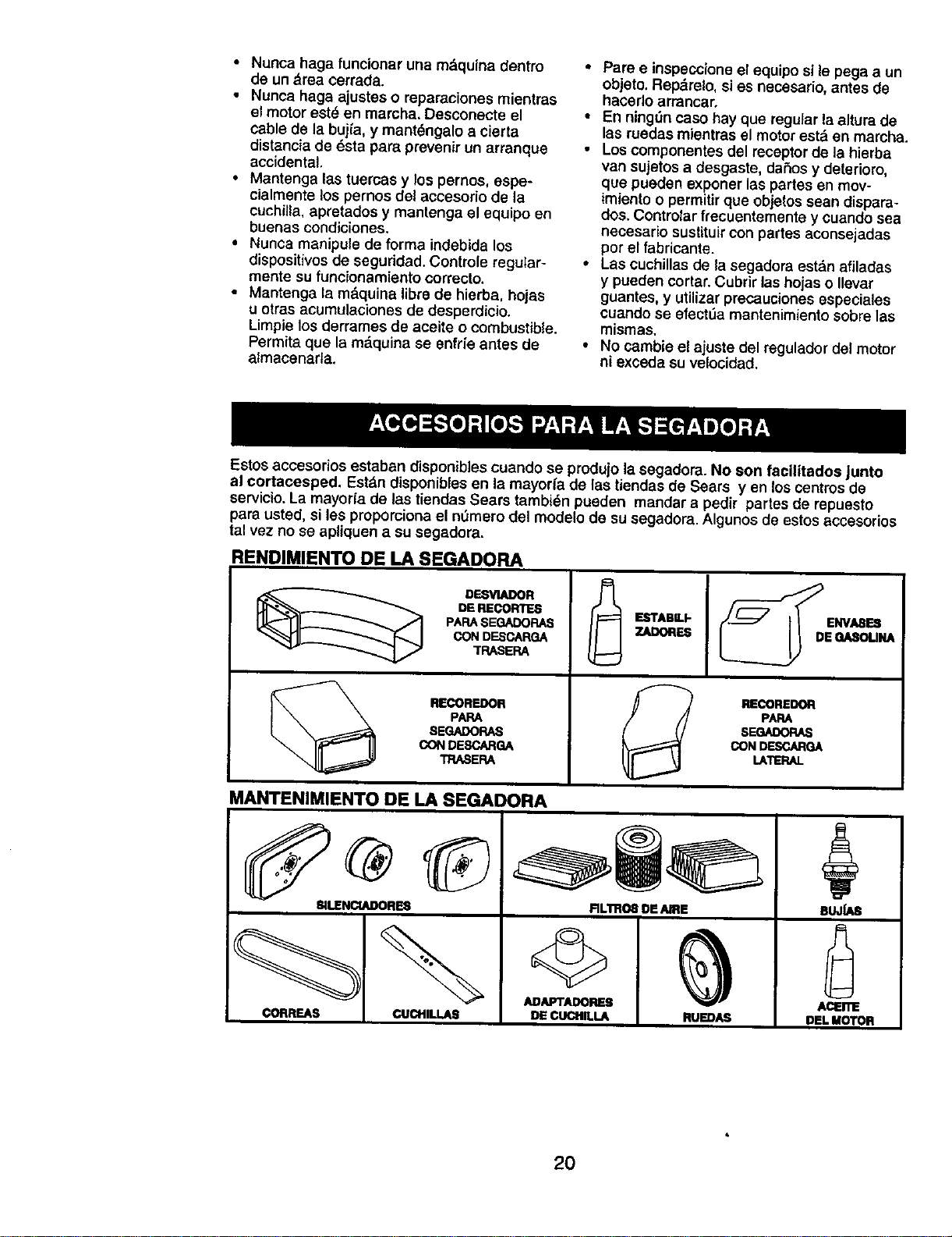
Estos accesorios estaban disponibles cuando $e produjo la segadora. No son fa¢llitados Junto
at cortecesped. Est_,ndisponibles en Lamayoda de las tiendas de Sears yen los centros de
servicio.La mayoda de las tiendas Sears tambi_n paeden mandar a pedir partes de repuesto
pare usted, si les propomiona el nOmarodel modelo de su segadora. Algunos de astos accesorios
tat vez no se aptiquen a su segadora,
RENDIMIENTO DE LA SEGADORA
DESVIADOR
DE RECORTES
PAPA SEGADORAS
CON DESCARGA
7RASERA
RECOREDOR
PAPA
8EGADORAS
CON DESCAFIGA
TRASERA
ESTABILP
==-
RECOREDOR
PAPA
S_
GONDESCARGA
LATERAL
MANTENIMIENTO DE LA SEGADORA
81LENCtADORE8
CORREAS ¢UCHILLAS
©
ADAPTADOflES
DE _LA
RLlmOE DE AIRE
RU_
BUJUUm
ACEnl_
DEk MOTOR
2O
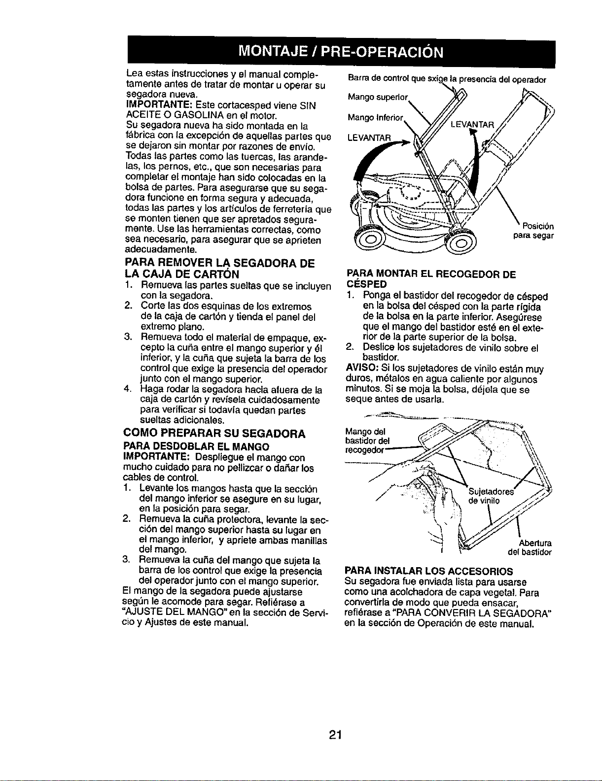
Lea estas instrucciones y el manual comple-
tamente antes de tratar de montar u operar su
segadora nueva.
IMPORTANTE: Este cortacesped viene SIN
ACEITE O GASOLINA en el motor.
Su segadora nueva ha sido montada en la
tabrica con la excepci6n de aqueltas partes que
se dejaron sin montar por razones de env(o.
Todas las partes come las tuercas, las arande-
las, los pernos, etc., que son necesarias para
completar et montaje ban sido colocadas en la
bolsa de panes. Para asegurarse que su sega-
dora funcione en forma segura y adecuada,
todas las partes y los articulos de ferreteria que
se monten tienen que ser apretados segura-
mente. Use las herramientas correctas, como
sea necesario, para asegurar que se aprieten
adecuadamente.
PARA REMOVER LA SEGADORA DE
LA CAJA DE CART(_N
1. Remueva las partes sueltas que se incluyen
con la segadora.
2. Corte las dos esquinas de los extremos
de la caja de cart6n y tienda el panel del
extremo piano.
3. Remueva todo el material de empaque, ex-
cepto la cuff;aentre el mango superior y 61
inferior,y la cuba que sujeta la barra de los
controlque exige la presencia del operador
junto con el mango superior.
4. Haga rodar la segadora hacia afuera de la
caja de cart6n y rev{seta cuidadosamente
para vedficar si todavfa quedan partes
sueltas adicionales.
COMO PREPARAR SU SEGADORA
PARA DESDOBLAR EL MANGO
IMPORTANTE: Despliegue el mango con
mucho culdado para no peUizcaro daSar los
cables de control.
1. Levante los mangos hasta que la seccibn
del mango inferiorse asegure en su lugar,
en la posici6n para segar.
2. Rernueva la cuSa proteetora, levante la sec-
ci6n del mango superior hasta su lugar en
el mango inferior, y apriete ambas manillas
del mango.
3. Remueva la cuSa del mango que sujeta la
barra de los control que exige la presencia
del operador junto con el mango superior.
El mango de la segadora puede ajustarse
seg_n le acomode para segar. Refi_rase a
"AJUSTE DEL MANGO" en la secci6n de Servi-
cioy Ajustes de este manual.
Barra de control
Mango superior
Mango In_rior
LEVANTAR
la presencia del operador
PosiciSn
para segar
PARA MONTAR EL RECOGEDOR DE
C_:SPED
1. Ponga el bastidor de1 recogedor de c6sped
en la bolsa del c_sped con la parte dgida
de la bolsa en la parte inferior.AsegQrese
que el mango del bastidor est6 en el exte-
rior de la parte superior de la bolsa.
2. Deslice los sujetadores de vinilo sobre el
bastidor.
AVI$O: Si los sujetadores de vinilo est&n mW
duros, m_talos en agua caliente por algunos
minutos. Si se moja ta bolsa, d_jeta que se
seque antes de usarla.
Mango del
bastidor de!
"-4
Abertura
I delbastidor
PARA INSTALAR LOS ACCESORIOS
Su segadora rue enviada lista para usarse
como una acolchadora de capa vegetal. Para
convertirla de modo que pueda ensacar,
refi(_rasea "PARA CONVERIR LA SEGADORA"
en ta seccibn de Operaci6n de este manual.
21
FAMILIARICESE CON SU SEGADORA
LEA ESTE MANUAL DEL DUEI_IOY LAS REGLAS DE SEGURIDAD ANTES DE OPERAR SU
SEGADORA. Compare las ilustraciones con su segadora para familiarizarse con la ubicaci6n de
los diversoscontroles y ajustes. Guarda este manual para referencia en el futuro.
Estos simbolos pueden apareser sobre su segadora o en la llteratura proporcionada con el
producto. Aprenda y comprenda $us significados.
ATTEN_)N O MOTOR MOTOR P_PtDO LENTO ESTRANGU COM- AGE_TE PELIGRO,GUARDE t.AS
ADVE_IA ENCENDIDO APAGADO LACIC_N BUSTIBLE MANOSY LOS PIES LEJOS
Control de
Barra de controlque exige
la presenda del operador
Controlde imputsi6n
arrancadcor
Manilla del mango
Tapa del deposito de
aceite del motorcon varilla
indicadora de nivet
Silenciador
Tapadeldeposito
dela gasolina Cubierta de
la impulsi6n
Filtrode alto'
Cebador
Ajustador de la rueda (en cada rueda)
IMPORTANTE: Este cortac_sped viene SIN ACEITE O GASOLINA en motor,
CUMPLE CON LOS REQUISITOS DE SEGURtDAD DE LA CPSC
Las segadoras a motor, que se conducen desda la parte de atrds, rotatorias, Sears, cumplen con
los estdndares de segurldad del American National Standards institute y de la U.S. Consumer
Product Safety Commission. La cuchUlagira cuando el motoresta funcionando.
Barra de control que ex|ge ta presencla del
operado - tiene que sujetar-se abajo, junto
COnel mango, para hacer arrancar el motor.
Su61telapara parar el motor.
Control de acelerolon/estrangulaclon - se
usa para haoer arrancar el motor y le permite
selecoionar la velocidad del motor de ya sea
R/_PIDA o LENTA.
Cord6n arrancador - se usa para hater ar-
rancar el motor.
Cebador - bombea combustible adicional
desda el carburador al cilindropara usa cuando
se necesita hacer arrancar un motorfrfo,
Palanca de control de la |mpulsi6n - se usa
para enganchar lasegadora para movimiento
hacia adelante impulsada a motor,
22
teojos de seguridad o protecci6n para los ojos
mientras opere su segadora o cuando haga
ajustes o reparaciones. Recomendamos gafas
o una mascara de seguridad de visi6n amplia
de seguridad usada sobre las gafas.
COMO USAR SU SEGADORA
VELOClDAD DEL MOTOR
La velocidad del motorse controla por medio
de un controlde ace]eraci6n ubicado en el lado
del mango superior. La posici6n de R,_PIDO se
usa para hacer arrancar el motor, para el corte
normal y un mejor ensacamiento del c_sped. La
posici6n LENTO es para corte liviano, recorte y
para economizar combustible.
• El movimiento hacia adelante parar& cuando
la barra de control que exige la presencia del
operador se suelta. Para parar el movimiento
hacia adelante sin parar el motor, suelte la
barra de control que exige la presencia del
operador un poco hasta que se desenganche
el control de la impulsion. Sujete la barra de
control que exige la presencia del operador
abajo en contra del mango para continuar
segando sin autoimpulsibn.
• Para mantener el control de la impulsi6n
enganchado cuando se de vuelta en las
esquinas, empuje el mango hac_aabajo y
levante las ruedas delanteras fuera del suelo
al girar la segadora.
Barradecontrolqueexige Controlde
lapresenciadeloperador laimpulsibn
RAPIDO
LENTO
PARA ENGANCHAR _.CONTROL DE LA
EL CONTROL DE IMPULSION
LA _MPULS|(DN OESENGANCHADO
PARA AJUSTAR LA ALTURA DE CORTE
Levante las ruedas para el corte bajo y baje las
ruedas para el corte alto., ajuste la altura de
corte para que se acomode a sus requisitos.La
posici6n del medio es la mejor para la mayorfa
de los c6spedes.
• Para cambiar la altura de corte, empuje la
palanca del ajustador hacia larueda. Mueva la
rueda hacia arriba o hacia abajo de modo que
se acomode a sos requisitos. Aseg0rese que
todas las ruedas queden igualmente ajustadas,
AVISO- El ajustador esta correctamente
colocado cuando las orejas de la placa est_n
insertadas en el agujero del mango. Tambi_n,
los ajustes de 9 posiciones (si equipado) per-
miten que el mango pueda ser movido entre las
orejas de la placa.
_NTROL DE ZONA DEL MOTOR
PRECAUCI6N. Las regulaciones federales
exigen que se instals un control para el motor
en esta segadora para reducir a un mfnimo el
riesgo de lesionarse debido al contacto con ta
cuchilla. Por ning5n motivotrate de eliminar
la funci6n del controldel cperador. La cuchilla
gira cuando el motor set&funcionando.
• Su segadora viene equipada con una barra
de controles que exigen la presencia del
operador, Io que requiere que el operador
est_ detrds del mango de la segadora para
hacerla arrancar y operarla.
CCONTROL DE LA IMPULSION
• La autoimpulsi6n se controla al sujetar la
barra de control que exige la presencia
del operador hacia abajo en el mango y al
empujar la palanca de controlde la impulsi6n
hacia adelante hasta que suene =clic,"luego
se suelta la palanca.
23
PARAUN CORTEALTO,
BAJELASRUEDAS
PARA UN CORTE BAJO, LEVANTE LAS RUEDAS
PARA CONVERTIR LA SEGADORA
Su segadora fue enviada lista para usarse
como acolchadora de capa vegetal, Para con-
vertir la a una operacibn de ensacado:
• Levantar la puerta trasera de cortacdsped
y colocar los ganchos del armaz6n de la
recolectora de hierba en los pasadores det
quicio de la puerta.
• Para pasar a la opercaibn de acolchamiento,
remover la recolectora de hierba y cerrar la
puerta trasera.
d_.°RECAUCI6N: No haga funcionar su sega-
dora sin puerta trasera cerrada o el desviador
de recortes o sin el recogedor de c0sped,
aprobados, en su lugar.Nunca trate de operar
la segadora cuando se ha removido la puerta
trasera o cuando estd un poco abierta.
,_._or del Mango del
trasera bastidordel
recogedor
de c_sped
Gancholateralde|
bastidordel recogedor
PARA VACIAR EL RECOGEDOR DE
ClaSPED
1. Levante el recogedor de c0sped usando el
mango del bastidor.
2. Remueva el recogedor de c_sped, con los
recortes, de debajo dal mango de la segao
dora.
3. Vacie los recortes de la bolsa usando tanto
el mango del basticlor como _I de la bolsa.
AVISO: No arrastre la bolsa cuando la vacie;
se producir_ un desgaste innecesado.
recogedor
de c_sped
Mangode
la bolsa
ANTES DE HACER ARRANCAR EL
MOTOR
AGREGUE ACEITE
Su segadora fue enviada sin aceite en el motor.
Para el tipoy el grado del aceite a utilizar,yea
el "MOTOR" en la secoi6n del Mantenimiento de
_1_ manual"
RECAUCION: NO sobrellene el motor con
aceite, o fumar_, cuando Io valla a arrancar.
1, Aseg_rese que la segadora est_ nivalada y
que el draa alrededor del depbsito de aceite
estd limpia.
2. Remueva la varila medidora de aceite del
tubo de desarga de aceite, AsegOrese que
el borda del tubo de relleno de aceita este
limpio. 24
3. Usted recibe un envase de aceite con la
unidad. Vierta lentamente el envase entero
de aceite en el tubode relleno del motor.
4. Permita que el aceite se asiente. Inserte
y apriete la varilla medidora de aceite,
despues remuevala para leer el nivel de
aceite.
5. AsegOrese de apretar la variUamedidora
del aceite antes de arrancar el motor.
• Revise el nivel del aceite antes de cada uso.
Agregue aceite si es necesario. Llene hasta
la I_neade Ileno en la varilla medidora de
niveL
• Cambie el aceite despuds de 25 horas de
operaci6n o una vez por temporada. Puede
necesitar ¢ambiar el aceite m0s a menudo
cuando las condiciones son polvorosas o
sucias.
AGREGUE GASOLINA
•Llene el estanque de combustible hasta
ia parte infedor del cuello de rellenodel
estanque de gasolina. No Io Uenedemasiado.
Use gasolina regular, sin plomo, nueva y lim-
pia con el mfnimo de 87 octanos. No mezcle
el aceite con la gasolina. Para asegurar
qua la gasolina utilizada sea fresca compre
estanques los cuales puadan ser utilizados
, durante los Rrimeros 30 dfas.
PRECAUCIbN: Limpie el aceite o el
combustible derramado. No almacene, derrame
o use gasolina cerca de una llama expuesta.
_I_PRECAUCI(_N: Los combustibles
mezclados con alcohol (conocidos como
gasohol, o el use de etanol o metanol) pueden
atraer la humedad, la que conduce a la
separaci6n y formaci6n de :_cidos durante el
almacenamiento, La gasolina acidica puede
daSar el sistema del combustible de un motor
durante el almacenamiento. Para evitar los
problemas con el motor, se debe vaciar el
sistema del combustible antes de guardarlo
por un perlodo de 30 dfas o mds. Vacfe el
estanque del combustible, haga arrancar el
motor y hdgalo funcionar basra que las lineas
del combustible y el carburador queden vacios.
La prbxima temporada use combustible nuevo.
Vea las Instruociones Para El Almacenamiento
para mds informaci6n. Nunca use productos de
limpieza para el motor o para el carburador en
el estanque del combustiblepues se pueden
producir daSos permanentes.
Tapa del
rellenador
de gasolina
"rapadel
de aceite
PARA HACER ARRANCAR EL MOTOR
AVISO; Debido alas capas protectopasdel mo-
tor,una cantidad pequeSa de humo puede es-
tar presente durante el use inicial del producto
y se debe eonsiderar normal.
1. Papahater arrancar un motor frfo, empuje
el cebador tres (3) veces antes de tratarlo.
Empuje firmemente. Este paso normal-
mente no es necesario cuando se hace
arrancar un motor que ya ha estado funcio-
nando per unos cuantos minutes.
2. Mueva la palanca de control de aceleraci6n
del motor a la posici6n de RAPIDO.
3. Sujete la barra de controles que exigen la
presencia del operador abajo en el mango
y tire el mango del arpancador r_pidamente.
No permita que el cordbn arrancador se
devuelva abruptamente.
PARA PARAR EL MOTOR
• Para parar el motor, suelte la barra de con-
troles que exigen la presencia del opepador.
AVISO" En climas m_.sfrfos puede que sea
necesario repetir los pasos del cebado. En cli-
mas rods calurosos el oebar demasiado puede
producir el ahogo y el motor no va a arrancar.
Si se ahoga el motor espere unos cuantos
minutes antes de tratar de hacerlo arrancar y
no repita los pasos del cebado.
CONSEJOS PARA SEGAR
• Bajo ciertas condiciones, tal come cdsped
muy alto, puede ser necesario el elevar la
altura del corte para reducir el esfuerzo
necesario para empujar la segadora y para
evitar sobrecargar el motor, dejando men-
tones de recortes de cdsped, Puede que sea
necesario reducir la velocidad del recorrido
y/o haga funcionar la segadora sobre el drea
per segunda vez.
• Para un corte muy pesado, reduzca el ancho
del torte pasando parcialmente per encima
del lugar anteriormente cortado y siegue
lentamente.
• Para un meier ensaoado del cdsped y para la
mayorfa de las condiciones de torte, la velo-
cidad del motor debe ajustarse a la posici6n
de R_.PIDO.
• Los pores en los recogedores de c_sped de
tela pueden Ilenarse con mugre y polvo con
el use y los recogedores recaudardn menos
c_sped. Para evitar _ste, rocie el recogedor
con la manguera de agua regularmente y
d_jelo secarse antes de usarlo.
• Mantenga la parte superior del motor, alred-
edor del arranoador, despejada y sin recortes
de c_sped y paja. Esto ayudard el flujo del
aire del motor y extender& su duraci_n.
CONSEJOS PARA SEGAR Y
ACOLCHAR
IMPORTANTE: Para obtenerel meier rendimiento
mantenga la caja de la segadora sin acumulacion
de cesped y basura. Vea "LIMPIEZA" in la seccion
Mantenimiento de este manual.
• La cuchilla acglchadora especial va a volver
a cortar los recortes de c_sped muchas
veces, y los reduce en tamaho, de mode que
si se caen en el c_sped se van a dispersar
entre _ste y no se van a notar.Tambi_n, el
c6sped acolchado se va a deshacer r&pidam-
ente entregando substancias nutritivas para
el c_sped, Siempre acolohe con la velocidad
del motor (cuchilla) m_s alta, pues as( se
obtendr_, la meier acci6n de recorte de las
cuchillas.
, Evite cortar el c_sped cuando est_ mojado.
El c_sped mojado tiende a formar montones
e interfiere con la acci6n de acolchado.
La meier hopa para segar el cSsped es
temprano en la tarde. A esa hopa 6ste se ha
seoado y el area reci6n cortada no quedar_
expuesta al sol directo.
• Para obtener los mejores resultados, ajuste
la altura del corte de la segadora de mode
que _sta corte solamente el tercio superior
de las hojas de c_sped. En el case de que el
c_sped haya crecido demaslado, puede ser
necesario el elevar la altura del corte para
reducir el esfuerzo necesario para empujar la
segadora y para evitar sebpacargar el motor,
dejando montones de recortes de c_sped.
Papa un c_sped muy pesado, reduzoa el an-
cho del corte pasando per encima del lugar
anteriormente cortado y siegue lentamente.
MAX1/3
•Ciertos tiposde cOspedy sus condiclones
pueden exigir que un drea tenga que ser
acolchada per segunda vez papa esoonder
completamente los recortes. Cuando se haga
el segundo corte, siegue atravesado o en
forma perpendicular a la pasada del primer
corte.
o Cambie su paten de torte de semana a
semana. Siegue de norte a sur una semana
y luego cambie de este a oeste la pr6xima
semana. Esto evitard que el c_sped se
enrede y cambie de direccibn.
25
//////.a/
PROG RAMA DE M AN T ENIMIE NTO//_//////
QUECOMPLETESUSERVICIOREGULAR /___O_/_,. FECHAS
Revlsatsihaysujetadoressueltos _ V'
Llmplar/In._onar elrecogederde
S c_;ped(elvleneequlpado) " _ k#'
Llmplar kl.segadom II_
_ U.m_i_de_'_ de _.aJbio_ de lakans-
rnisi_n(seoadorasconpoderpropulsor) II/
_ ReVlsar las colTeas y IM poleas Impul- .j
(segaderasconpoderpropulsor)
Revisaro/sfilar/cambiatlacuctdlla a
AR Tebladelubdcaci&n II_
LlmplarIsbaterfa/recargar
(segadorasoonarranqueel_lCo) I/ I/4
M Revis_elniveldelecolte I_
Camblarela_eltedelmotor _1,,I
_ LL,_plerelflttmdeaJre _,,;tInspe_,ionarelsilenciador
R Umpiare/cambiarlabujl'a I_
deCam_ar"lreelcamJchodopapelde__tro _:1
1 - Clu_biar n_s a ntenudo cuando se ope_e ba_ocarg4speseda o en lu_ble_tes €on oJtss tem_m_.
2 - DM sen&:_0 m4s a menudo ¢uando se opera en _r_Idones suclas 0 polvorosas.
3 - Camble bs oJChlllas mds a menudo cusndo slegue en temmo aren060.
4 - C4ug_ pot 48 hotas id fin de la tempord_a.
RECOMENDACIONES GENERALES
La garantia de esta sagadora no cubre los
artfculos que han estado sujetos al abuso o a
ta negtigencia det operador. Para recibir todo
el valor de la garantfa, el operador Uene que
mantener la segadora seg0n las instrucciones
descritas en este manual
Hay algunos ajustes que se tienen que hacer
en forma periSdica para poder mantener su
unidad adeeuadamente.
Todos los ajustes en la seccion de Servicio y
Ajustes de este manual tienen que set revisa-
dos per Io menos un vez pot oada temporada,
. Una vez al aSo, cambie la bujfa, limpie o
cambie el elemento del filtro de aire y revise
si la cuchilla estd desgastada. Una bujfa
nueva y un elemento del filtro de aire limpio/
nuevo aseguren la mezcla de aire.-combus-
tible adecuada y ayudan a que su motor
funcione mejor y que dure m&s.
• Siga el programa de mantenimiento en este
manual,
TABLA DE LUBRICACI( N
Ajustador
de la rueda
(_) Aceite
del
motor
Bisagra
k _ _ _ ) de
puerta
traser
(_ C'lavija de mOntaje del puntal del mango
ANTES DE CADA USO
1. Revise el niveldel aceite del motor.
2. Revise sihay sujetadores sueltos,
LUBRICACION
Manlenga la unidad bien lubricada (yea ta
"TABLA DE LUBRICACI(_N").
(_ Rocieel lubrlcante
,_ Yea "MOTOR"en lasection de Mantenlmlento
IMPORTANTE: NOaceite o engrase los
rodamientos de la rueda de plastico.Los
lubricantes viscosos atearan polvo y mugre,
Io acortare la duracion de los rodamientos
autolubricantes. Si cree que tienen que
lubricarse, use Ios6mente un lubricante tipo
crafito, de polvo seco, en forma moderada.
26
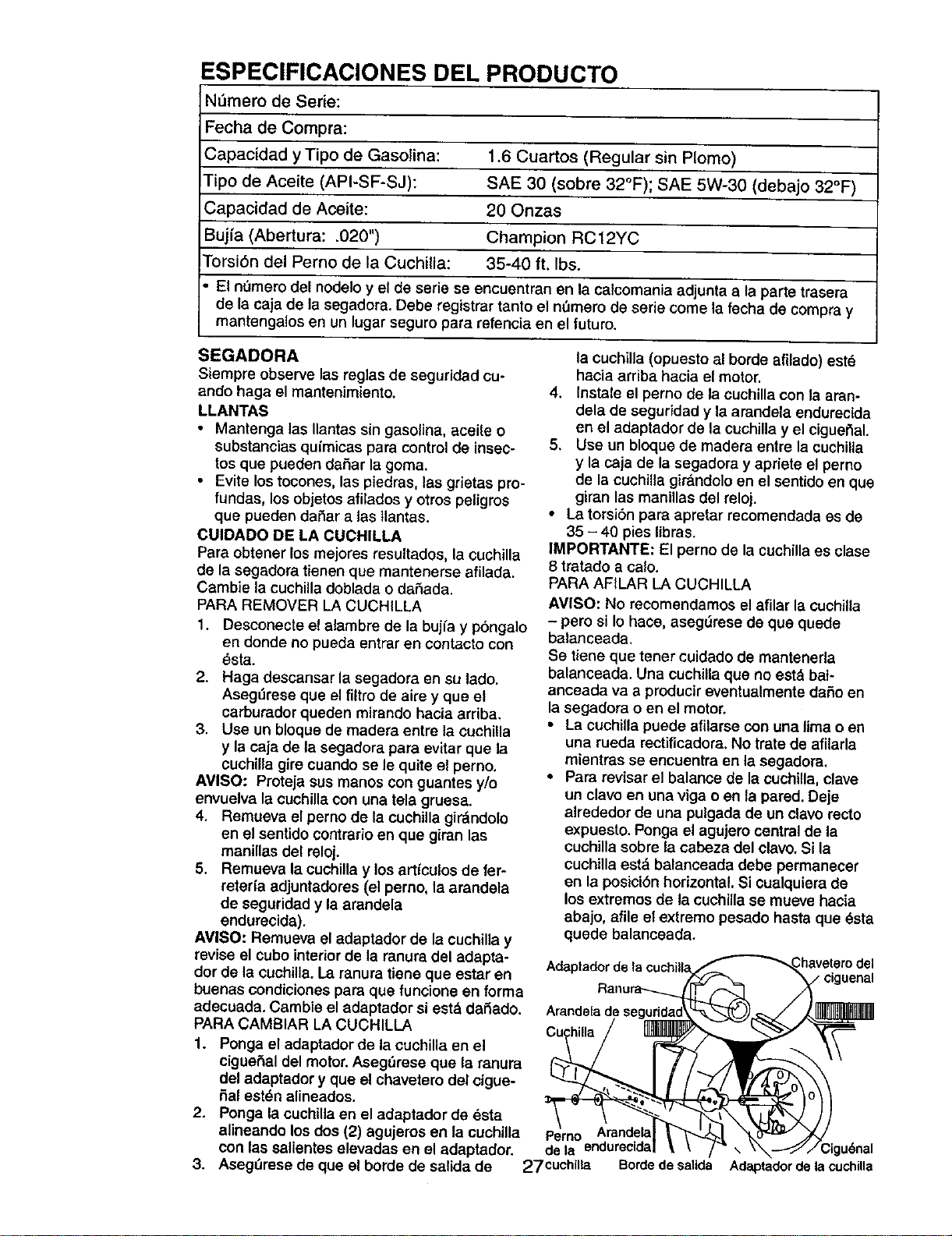
ESPECIFICACIONES DEL PRODUCTO
N_mero de Serie:
Fecha de Compra:
Capacidad y Tipo de Gasolina: 1.6 Cuartos (Regular sin Plomo)
Tipo de Aceite (API-SF-SJ): SAE 30 (sobre 32°F); SAE 5W-30 (debajo 32°F)
Capacidad de Aceite: 20 Onzas
Bujfa (Abertura: .020") Champion RC 12YC
Torsi6n del Perno de la Cuchilla: 35-40 ft. Ibs.
El nOrnero del nodelo y el de serie se encuentran en la calcomania adjunta a la parte trasera
de la caja de la segadora. Debe registrar tanto el nemero de serie come la fecha de compra y
mantengalos en un luga_ seguro para re'fencia en el future.
SEGADORA
Siempre observe las reglas de seguridad cu-
ando haga el mantenimiento.
LLANTAS
• Mantenga las Ilantas sin gasolina, aceite o
substancias qu{micas para control de insec-
tos que pueden da5ar la goma.
• Evite los tocones, las piedras, las grietas pro-
fundas, los objetos afilados y otros peligros
que pueden dafiar a tas tlantas.
CUIDADO DE LA CUCHILLA
Para obtener los mejores resultados, la cuchilla
de la segadora tienen que mantenerse afilada.
Cambie la cuchilla doblada o daSada.
PARA REMOVER LA CUCHILLA
1. Desconecte el alambre de la bujfa y p6ngalo
en donde no pueda entrar en contacto con
_sta.
2. Haga descansar la segadora en su lade.
Aseg_irese que el filtro de aire y que el
carburador queden mirando hacla arriba.
3. Use un bloque de madera entre la cuchilla
y la caja de la segadora para evitar que la
cuchilla gire cuando se le quite el perno.
AVISO" Proteja sus manes con guantes y/o
envuelva la cuchilla con una tela gruesa.
4. Remueva el perno de la cuchilla gir_ndolo
en el sentido contrario en que giran las
manillas del reloj.
5. Remueva la cuchilla y los artfculos de fer-
reteda adjuntadores (el perno, la arandela
de seguridad y la arandela
endurecida).
AVISO: Remueva el adaptador de la cuchilla y
revise el cube interior de la ranura del adapta-
dor de la cuchilla. La ranura tiene que estar en
buenas condiciones para que funcione en forma
adecuada. Cambie el adaptador si est_ daSado.
PARA CAMBIAR LA CUCH{LLA
1. Ponga el adaptador de la cuchilla en el
cigue5al del motor. Aseg6rese que la ranura
del adaptador y que el chavetero del cigue-
hal est_n alineados.
2. Ponga la cuchilla en el adaptador de esta
la cuchilla (opuesto al borde afilado) est6
hacia arriba hacia el motor,
4. Instale el perno de la cuchina con la aran-
dela de seguridad y la arandela endurecida
en el adaptador de la cuchilla y el ciguer_al.
5, Use un bloque de madera entre la cuchiUa
y la caja de la segadora y apriete el perno
de la cuchilla girdndolo en el sentido en que
giran las manillas del reloj.
• La tersi6n para apretar recomendada es de
35 - 40 pies libras.
IMPORTANTE: El perno de la cuchilla es clase
8 tratado a calo.
PARA AFILAR LA CUCHILLA
AVISO: No recomendamos el afilar la cuchilla
- pero si Io hace, asegOrese de que quede
balanceada.
Se tiene que tener cuidado de mantenerla
balanceada. Una cuchilla que no est&bal-
anceada va a producir eventualmente daSo en
la segadora o en el motor.
• La cuchilla puede afilarse con una lima o en
una rueda rectificadora. No trate de afllarla
mientras se encuentra en la segadora,
• Para revisar el balance de la cuchilla, clave
un clave en una riga o en la pared. Deje
alrededor de una pulgada de un clave recto
expuesto. Ponga el agujero central de la
cuchilla sobre la cabeza del clave. Si la
cuchilla est_ balaneeada debe permanecer
en la posici6n horizontal. Si ¢ualquiera de
los extremes de la cuch{llase mueve hacia
abajo, afile el extreme pesado hasta que _sta
quede balanceada.
Adap'[adorde |a cuclT=||a
alineando los dos (2) agujeros en la cuchllla Perno Arandela
con las salientes elevadas en el adaptador, de la endurecida
3. AsegQrese de que el borde de salida de 27 cuchilla Bordede salida
Adaptador de la cuchilla
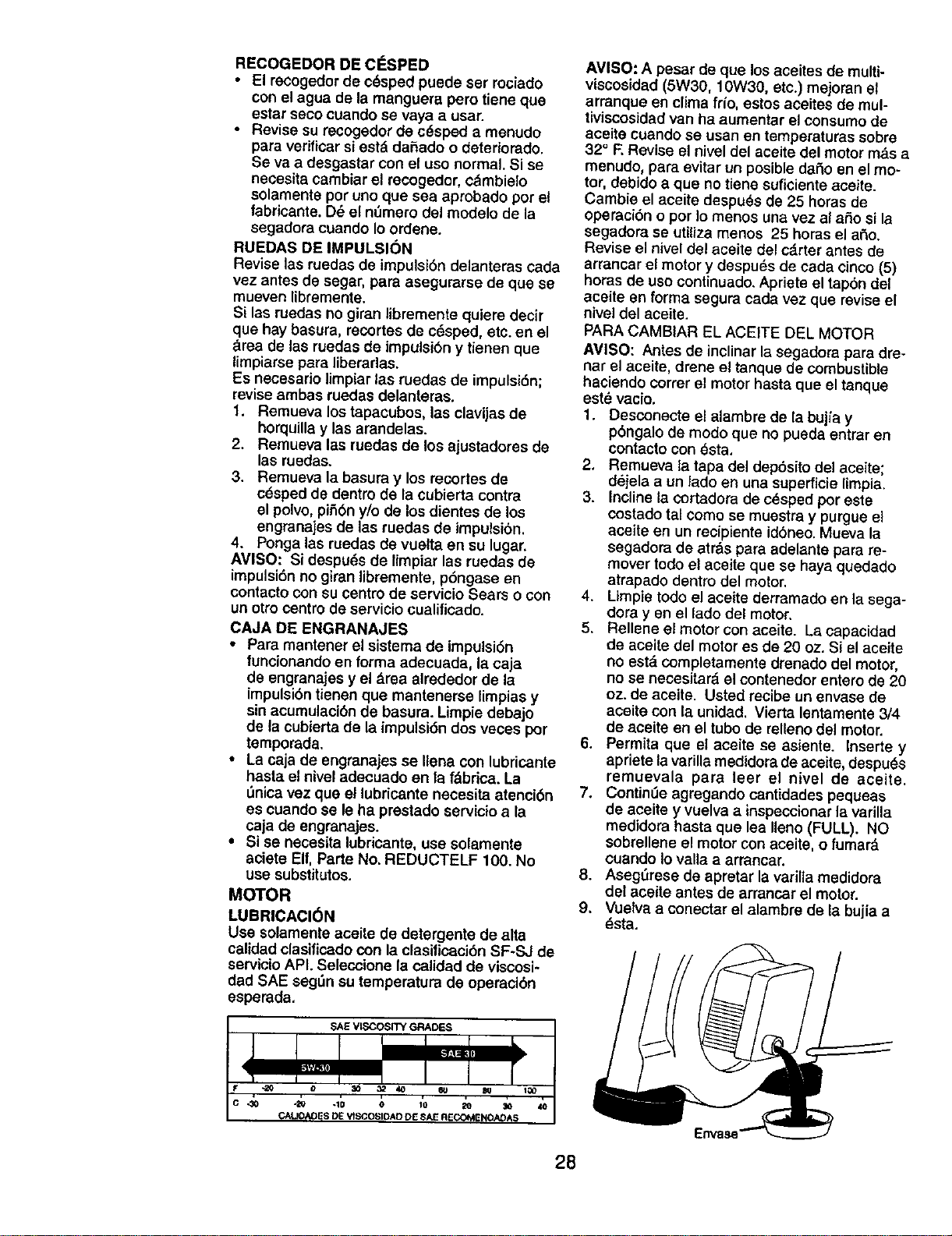
RECOGEDOR DE ClaSPED
• El reCogedor de ¢_sped puede ser rociado
con el agua de la manguera pero tiene que
estar seco cuando se vaya a usar.
• Revise su recogedor de c_sped a menudo
para verificar siest& dahado o deteriorado.
Se va a desgastar con el uso normal. Si se
necositacambiar el recogedor, ¢&mbielo
solamente per uno que sea aprobado por et
tabricante. D_ e{ n_mero del modelo de la
segadora cuando Io ordene.
RUEDAS DE IMPULSIC)N
Revise las ruedas de impulsibn detanteras cada
vez antes de segar, para asegurarse de que se
mueven libremente.
Si las ruedas no giran libremente quiere decir
que hay basura, recortes de c_sped, etc. en el
_rea de las ruedas de impulsi6n y tienen que
limpiarse para liberarlas.
Es necesario limpiar las ruedas de impulsi6n;
revise ambas ruedas delanteras.
1. Remueva los tapacubos, las clavijas de
horquilla y las arandelas.
2. Remueva las ruedas de los ajustadores de
las ruedas.
3. Remueva la basura y los recortes de
c_sped de dentro de la cubierta contra
el polvo,pi_bn y/o de los dientes de los
engranajes de las ruedas de impulsibn.
4. Ponga las ruedas de vuelta en su lugar.
AMISO: Si despu_s de limpiar las ruedas de
impulsi6n no giran libremente, p6ngase en
contacto con su centro de servicio Sears o con
un otto centro de servicio cualificado.
CAJA DE ENGRANAJES
• Para mantener el sistema de impulsi6n
funclonando en forma adecuada, la caja
de engranaies y el drea alrededor de la
impulsi6ntienen qua mantenerse limpias y
sin acumulaci6n de basura. Limpie debajo
de la cubierta de la impulsi6n dos veces por
temporada.
• La caja de engranajes se Ilena con lubricante
hasta el nivel adecuado en la f_ibrica. La
0nica vez que el lubricante necesita atenci6n
es cuando se le ha prestado servicio a la
caja de engranajes.
• Si se necesita tubricante, use solamente
aciete Elf, Parte No, REDUCTELF 100. No
use substitutos.
MOTOR
LUBRICACION
Use solamente aceite de detergente de alta
calidad clasificadocon la clasilicaci6n SF-SJ de
servicio API. Seleccione la calidad de viscosi-
dad SAE seg0n su temperatura de operaci6n
esperada.
SAE VI_SITY GRADES
AVISO: A pesar de que los aceites de multi-
viscosidad (5W30, 10W30, etc.) mejoran el
arranque en clima frio, estos aceites de mul-
tiviscosidad van ha aumentar el consumo de
aceite cuando se usan en temperaturas sobre
32° F, Revise el niveldel aceite del motor m&sa
menudo, para evitar un posible dar_oen el mo-
tor, debido a que no tiene suficiente acelte.
Cambie el aceite despu_s de 25 horas de
operaci6n o pot _omenos una vez al afio si la
segadora se utiliza menos 25 horas el aSo.
Revise el nivel del aceite del c_.rter antes de
arrancar el motor y despu_s de eada cinco (5)
horas de uso continuado. Apriete el tap6n del
aceite en forma segura cada vez que revise el
nivel del aceite.
PARA CAMBIAR EL ACEITE DEL MOTOR
AVISO: Antes de inclinar la segadora para dre-
nar el aceite, drene el tanque de combustible
haciendo correr el motor hasta que el tanque
est_ vacio.
1, Desconecte el alambre de la buj_a y
p6ngalo de modo que no pueda entrar en
contacto con _sta.
2, Remueva la tapa del dep6sito del aceite;
dejela a un lado en una superficie limpia.
3. Incline la cortadora de c6sped por este
costado tal como se muestra y purgue e]
aceite en un recipiente id6neo. Mueva ta
segadora de atr&s para adelante para re-
mover todo el aceite que se haya quedado
atrapado dentro del motor.
4. Limpie todo el aceite derramado en la sega-
dora yen el lado del motor.
5. Rellene el motor con aceite. La capacidad
de aceite del motor es de 20 oz. Si el aceite
no est& completamente drenado del motor,
no se necesitar_ el contenedor entero de 20
oz. de aceite. Usted recibe un envase de
aceite con la unidad. Vierta lentamente 3/4
de aceite en el tubo de relleno del motor.
6. Permita que el aceite se asiente. Inserte y
apriete la varilla medidora de aceite, despu_s
remuevala para leer el nivel de aceite.
7. Contin0e agregando cantidades pequeas
de aceite y vuelva a inspeccionar la varilla
medidora hasta que lea Ileno (FULL). NO
sobrellene el motor con aeeite, o {umar&
euando Iovalla a arrancar.
8. Aseg0rese de apretar la varilla medidora
de[ acoite antes de arrancar el motor.
9, Vuelva a conectar el alambre de la bujia a
_sta.
28
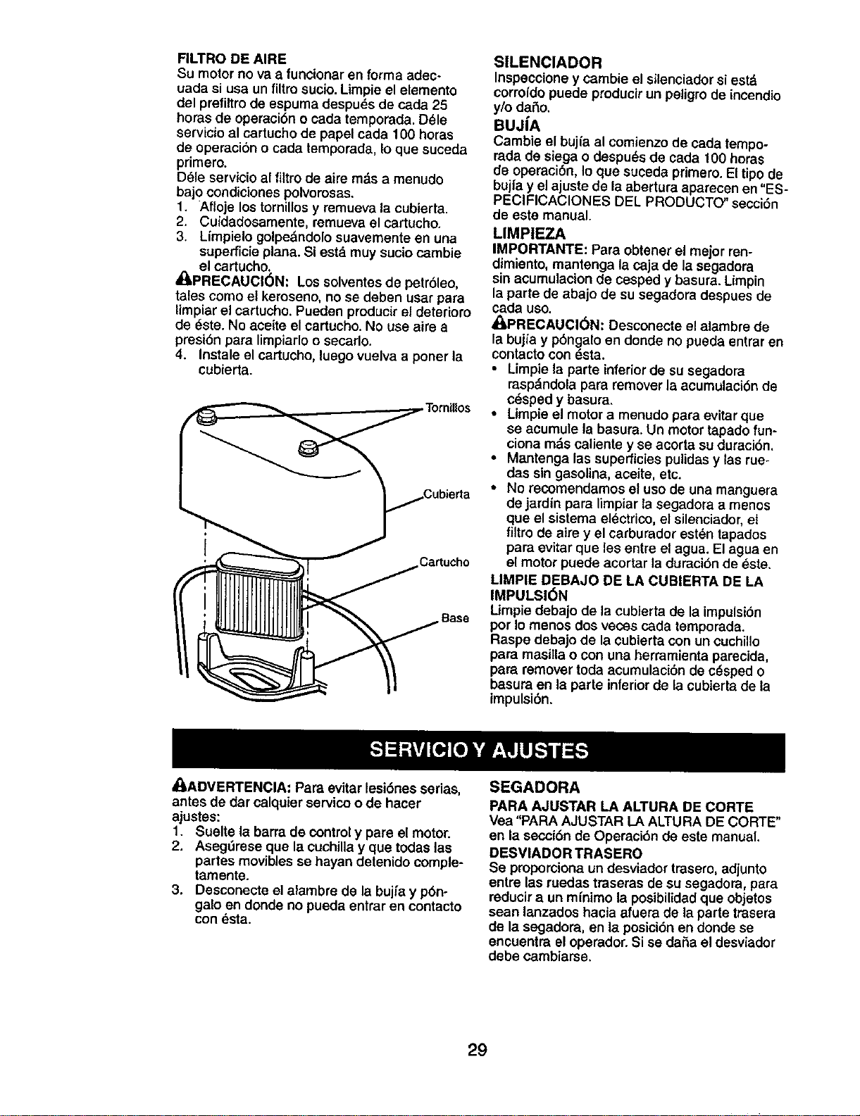
FILTRO DE AIRE
Su motor no va a funcionar en forma adec-
uada si usa un filtro sucio. Limpie el elemento
del prefiltro de espuma despuds de cada 25
hopasde opepacibno cada tempopada.D_le
servicio al cartucho de papel cada 100 horas
de operaci6n o cada temporada, Io que suceda
primero.
D_le servicio al filtro de aire m_s a menudo
bajo condiciones polverosas.
1. Afloje los tornillos y remueva la cubierta.
2. Cuidadosamente, remueva el cartucho.
3. Limpielo golpe&ndolo suavemente en una
superficie plana. Si est,. muy sucio cambie
el cartucho.
_[I'PRECAUCl6N: Los solventes de petr61eo,
tales como el keroseno, no se deben usar para
Iimpiar el cartucho. Pueden producir el deterioro
de dste. No aoeite el cartucho. No use aire a
presi6n para limpiarlo o secarlo.
4. Instale el cartucho, luego vuelva a porter la
cubierta.
Ca_ucho
SILENCIADOR
Inspeccione y cambie el silenciador si estd
corrofdo puede producir un peligro de incendio
y/o dafio.
BUJ[A
Cambie el bujfa al comienzo de cada tempo-
Padade siega o despu_s de cada 100 hopas
de opepaci6n,Io que suceda primero. El tipo de
bujfay el ajuste de la abertura aparecen en "ES-
PEClFICACIONES DEL PRODUCTO" secci6n
de este manual.
LIMPIEZA
IMPORTANTE: Papaobtener el mejor ren-
dimiento, mantenga la caja de la segadora
sin aeumulacion de cesped y basura. Limpin
la parte de abajo de su segadora despues de
cada uso.
_PRECAUCI6N: Desconecte el alambre de
la bujfa y pbngalo en donde no pueda entrar en
contacto con _sta.
• Limpie la parte inferior de su segadora
Pasp&ndola para remover la acumulaci6n de
c_sped y basura.
• Limpie el motor a menudo para evitar que
se acumule la basupa. Un motor tapado fun-
ciona rods caliente y se acorta su dupaci6n.
• Mantenga las superficies pulidas y las rue-
das sin gasolina, aceite, etc.
• No recomendamos el uso de una manguera
de jardin para limpiar la segadora a menos
que el sistema electrico, el silenciador, el
filtro de aire y el carburador est_n tapados
para evitar que les entre el agua. El agua en
el motor puede acortar la duraci6n de _ste.
LIMPIE DEBAJO DE LA CUBIERTA DE LA
IMPULSI6N
Llmpie debajo de la cubierta de la impulsi6n
por Io menos dos veces cada tempopada,
Raspe debajo de la cubierta con un cuchillo
para masitla o con una herramienta parecida,
para remover teda acumulaci6n de c_sped o
basupaen la parte inferiorde la cubierta de la
impulsi6n,
/I, ADVERTENCIA: PaPaevitar lesi6nes serias,
antes de dar calquier servico o de hacer
ajustes:
1. Suelte la barra de controly pare el motor.
2. Asegdrese que la cuchilla y que todas las
partes movibles se hayan detenido comple-
tamente.
3. Desconecte el alambre de la bujfa y p6n-
galo en donde no pueda entrar en contacto
con esta.
SEGADORA
PARA AJUSTAR LA ALTURA DE CORTE
Vea "PARA AJUSTAR LA ALTURA DE CORTE"
en la secci6n de Opepaci6n de este manual.
DESVIADOR TRASERO
Se proporciona un desviador trasero, adjunto
entre las ruedas tpaseras de su segadora, para
reducir a un mfnimo la posibilidadque objetos
sean lanzados hacia afuera de la parte trasera
de la segadora, en la posici6n en donde se
encuentpa el opepador.Si se dafia el desviador
debe cambiarse,
29
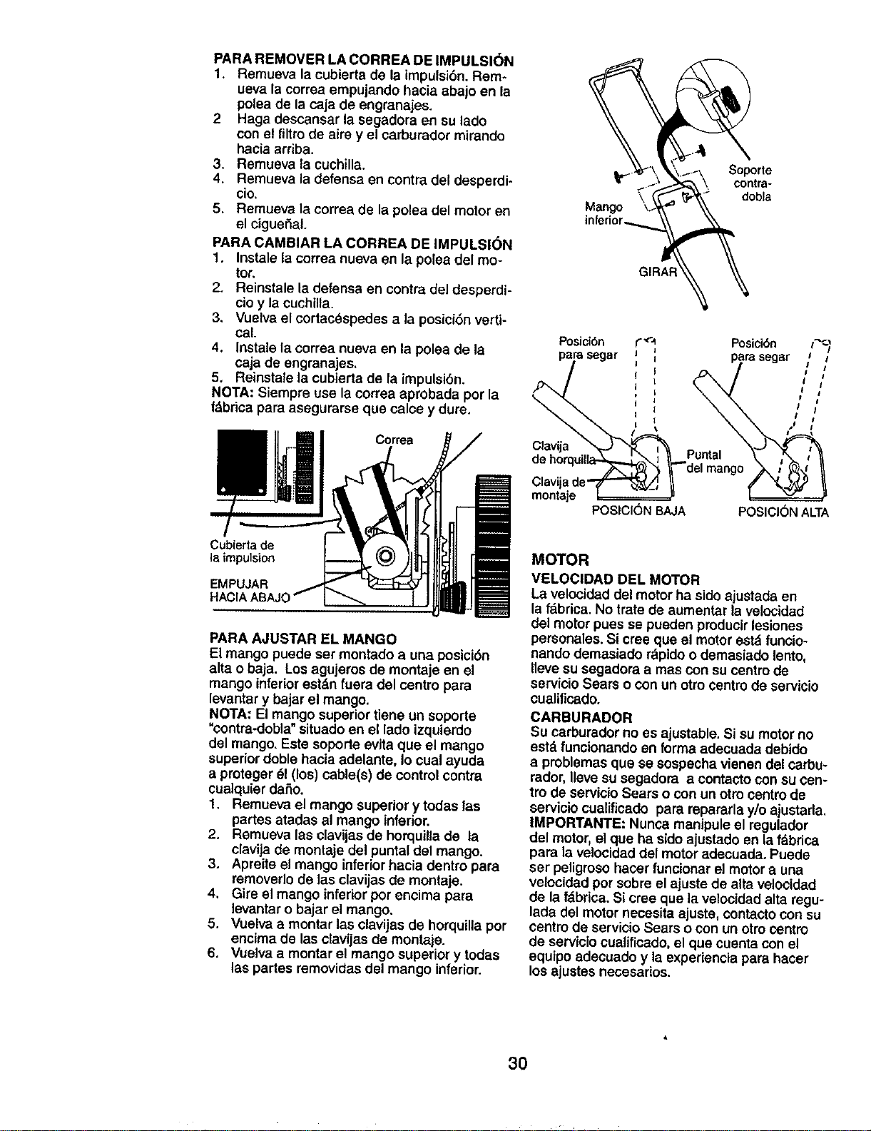
PARA REMOVER LA CORREA DE IMPULSI_)N
1. Remueva la cubierta de la impulsi6n. Rem-
ueva la correa empujando hacia abajo en la
pelea de la caja de engranajes.
2 Haga descansar la segadora en su lado
con el filtrode aira y el earburador mirando
haeia arriba.
3. Remueva la cuchilla.
4. Remueva la defenea en contra del desperdi-
cio.
5. Remueva la correa de la polea del motor en
el cigueSal.
PARA CAMBIAR LA CORREA DE IMPULSK_N
1. Instale la correa nueva en la polea del mo-
tor.
2, Reinstale Ladefensa en contra del desperdi-
cioy la euchilla.
3, Vuelva el cortacOspedes a la posici6n verti-
cal.
4. Instale la correa nueva en la polea de la
caje de engranajee,
5, Reinstale la cubierta de la impulsibn.
NOTA: Siempre use la correa aprobada por la
f&brica para asegurarse que calee y dure,
Cortea
Soporte
_'_" \ contra-
dobla
Mango
GIRA_
Posici6n
a segar
Clavija
montaje
I
POSICl0N BAJA
Posici6n r_
parasegar /
[ I'
p J
I i
I I
POSIClONALTA
Cubierta de
la impulsion
PARA AJUSTAR EL MANGO
El mango puede ser montado a una posicibn
alta o baja. Los agujeros de montaje en el
mango inferior est_n fuera del centro para
levantary bajar el mango.
NOTA: El mango superior tiene un soporte
"contra-dobla" eituado en el lado izquierdo
del mango. Este soperte evita que el mango
superior doble hacia adelante, Io cual ayuda
a proteger _1(los) cable(e) de control contra
eualquier dafio.
1. Remueva el mango superior y todas las
partes atadas al mango inferior.
2. Remueva las clavijas de horquilla de la
clavija de montaje del puntal del mango.
3. Apt'eite el mango interior hacia dent_o para
removerlo de las clavijas de montaje.
4. Gire el mango inferior per encima para
levantar o bajar el mango.
5. Vuelva a montar las clavijas de horquilla por
encima de las ctavijas de montaje.
6. Vuelva a montar el mango superior y todas
las partes removidas del mango inferior.
MOTOR
VELOCIDAD DEL MOTOR
La velocidad del motor ha sido ajustada en
la fdbrica. No irate de aumentar la velocidad
del motor pues se pueden producirleeiones
personales. Si cree que el motor eetd funcio-
nando demasiado rdpidoo demasiado lento,
Ileve su segadora amas con su centrode
eervicio Sears o con un otrocentro de servieio
cualificado.
CARBURADOR
Su carburador no es ajuetable. Si su motorno
estd funcionando en forma adecuada debido
a problemae que ee eospecha vienen del carbu-
rador, Uevesu segadora a contacto con su con-
fro de servicio Sears o con un otro centrode
eervicio cualificado para repararla y/o ajustarla,
IMPORTANTE: Nunca manipule el regulador
del motor, el que ha sido ajustado en la fdbrica
para la velocidad del motoradecuada. Puede
set petigroeo hater funoonar el motor a una
velocidad per eobre el ajuste de alta velocidad
de la f&brica. Si cree que la velocidad alta regu-
lada del motorneceeita ajuete, contacto con su
eentro de servicio Sears o con un otro centro
de servicio cualificado, el que cuenta con el
equipo adecuado y la experiencia para hacer
los ajustes necesarios.
30
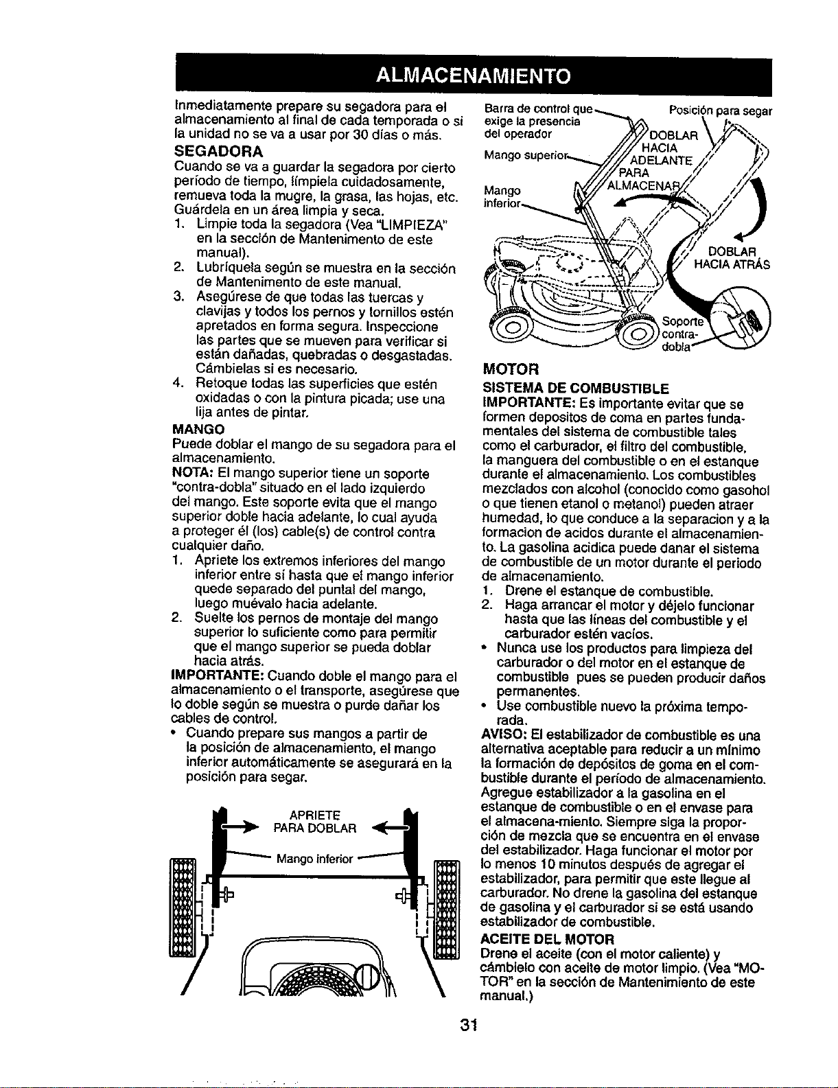
Inmediatamente prepare su segadora para el
almacenamiento al final de cada temporada o si
la unidad no se va a usar per 30 dias o re&s.
SEGADORA
Cuando se vaa guarder la segadora per cleric
per{ode de tiempo, Iimpiela cuidadosamente,
remueva toda la mugre, la grasa, las hojas, etc.
Gudrdela en un drea limpia y seca.
1. Limpie toda la segadora (Vea "LIMPIEZA"
en la seccibn de Mantenimento de este
manual).
2. Lubrfquela seg,3n se muestra en la secci6n
de Mantenimento de este manual.
3. Aseg_rese de que todas las tuercas y
clavijas y todos los pernos y tornillos est6n
apretados en forma segura. Inspeccione
las partes que se mueven pare verificar si
estan dar3adas, quebradas o desgastadas,
C,_mbielas si es necesario.
4. Retoque todas las superficies que est_n
oxidadas o con la pintura picada; use una
lija antes de pintar.
MANGO
Puede doblar el mango de su segadora para el
almacenamiento.
NOTA: El mango superior tiene un soporte
"contra-dobla" situado en el lade izquierdo
del mango. Este soporte evita que el mango
superior doble hacia adelante, Io cual ayuda
a proteger 61(los) cable(s) de control centre
cualquier daSo.
1. Apriete los extremes inferiores del mango
inferior entre si hasta que el mango inferior
quede separado del puntal del mango,
luego mu_valo hacia adelante.
2. Suelte los pernos de montaje del mango
superior Io suficiente come pare permitir
que el mango superior se pueda doblar
hacia at_s.
IMPORTANTE: Cuando doble el mango Data el
almacenamiento o el transporte, asegOrese que
Io doble seg_n se muestra o purde daSar los
cables de control.
• Cuando prepare sus mangos a partir de
la posicibn de almacenamiento, el mango
inferior autom_,ticamente se asegurar& en la
posicibn para segar,
APRIETE
PARA DOBLAR
Mang,
Barra de control
exige la presencia
deeoperador
Posici6n para segar
Mango
DOBLAR
HACIA ATRAS
MOTOR
SISTEMA DE COMBUSTIBLE
IMPORTANTE: Es importante evitar que se
formen depositos de coma en partes funda-
menta}es det sistema de combustible tales
como el carburader, el filtro del combustible,
la manguera del combustible o en el estanque
durante el almacenamiento, Los combustibles
mezclados con alcohol (conocidocome gasohol
o que tienen etanol o metanol) pueden atraer
humedad. Io que conduce ala separacion y a le
formacion de acidos durante el almacenamien-
to. La gasolina acidica puede danar el sistema
de combustible de un motordurante el periodo
de almacenamiento.
1. Drene el estanque de combustible.
2. Haga arrancar el motor y d_jelo funcionar
hasta que las I(neas del combustible y el
carburador est_n vacios.
• Nunca use los productos para limpieza del
carburader o del motor en el estanque de
combustible pues se pueden producir daiios
permanentes.
• Use combustible nuevo la prbxima tempo-
rada,
AVISO: El estabilizador de combustible es una
alternative aceptable para reducir a un mlnimo
la formacibn de dep6sitos de goma en el com-
bustible durante el per_odo de almacenamiento.
Agregue estabilizador a la gasolina en el
estanque de combustibteo en el envase pare
el almacena-miento. Siempre siga la propor-
cibn de mezcla que se encuentra en et envase
del estabilizador. Haga funcionar el motor per
Io menos 10 minutes despu_s de agregar el
estabilizador, para permitir que este Ilegue al
carburador. No drene la gasetina del estanque
de gasolina y el carburador si se est&usando
estabilizador de combustible.
ACEITE DEL MOTOR
Drene el aceite (con el motor caliente) y
c_mbielo con aceite de motor limpio.(Vea "MO-
TOR" en la seccibn de Mantenimiento de este
manual.)
31
CILINDRO
1. Remueva la buj|a.
2. Vacfe 29 ml (una onza) de aceite a tray,s
del agujero de la bujfa en el cilindro.
3. Tire la manilta de arranque lentamente unas
cuantas veces para distribuir el aceite.
4. Cambie por una bujfa nueva.
OTROS
, No guarde la gasolina de una temporada a la
otra.
• Gamble el envase de la gasolina si se emp-
ieza a oxidar. La oxidaci6n y/o la mugre en
su gasolina produoir&n problemas.
• Si es posible, guarde su unidad en un recinto
cerrado y c_brala para protegerla contra el
polvo y la mugre.
• Cubra su unidad con un forro protector
adecuado que no retenga la humedad. No
use pldsUco. El pl._stico no puede respirar, Io
que permite la formaci6n de condensaci6n,
Io que produeird la oxidaci6n de su unidad.
IMPORTANTE: Nunca cubra la segadora mien-
tras el motor y las areas de escape to davia
estan calientes.
_I_PRECAUCI6N: Nunca almacene la sega-
dora con gasolina en el estanque dentro de un
edificio en donde los gases pueden alcanzar
una llama expuesta o una chispa. Permita que
se enfrfe el motor antes de alma-cenarla en
algOn recinto cerrado.
SOLUCION DE PROBLEMAS - Vea la seccl6n apropiada en el manual amenos que
estd dirigldo a un centro de servico Sears.
PROBLEMA
No arranca 1.
2.
3.
4.
CAUSA CORRECCI6N
Filtrode aire sucio.
Sin combustible.
Combustible rancio.
Agua en el combustible.
5. Alambre de la bujfadesconectado.
6. Buji'a mala.
7. Cuchilla suelta o adaptador
de la cuchilla quebrado.
8. Barra de control en la
posicibn suelta,
9. Barra de control defectuosa.
10. V._lvula del combustible (si equ-
ipada) est,. en la posici6n OFF.
11. Baterfa ddbi (si equipada).
12. Desoonecte el conector
de la baterfa (si equipada).
1. Limpie/cambie el filtro de aire.
2. Llene el estanque de combustible.
3. Drene el estanque y vuelva a
Ilenarlo con combustible limpio
y nuevo.
4, Drene el estanque de combustible
y el carburador y vuelva a Ilenar el
estanque con gasolina nueva.
5. Conecte el alambre a la bujfa.
6, Cambie la bujfa.
7, Apriete el perno de la cuchilla
cambie el adaptador de la cuchilla.
8, Presione la barre de control
hacia el mango.
9. Cambie la barra de control.
10. Gire a la vdlvula del combustible
a la posici6n ON.
11. Cague la baterfa.
12. Conecte la bateda al motor.
32
PROBLEMA
Falta de
fuerza
Mal corte-
d|sparejo
Vibracidn
exces|va
Cord6n
arrancador
dtf{cil de t|rar
Recogedor de
cdsped no se
Ilena (sl v|ene
equlpado)
Diffcll de
empujar
P6rdlda de
impulsl6n
o retardase
de la
velocldad
CAUSA
1. Cuchilla desgastada, doblada
o suelta.
2. Altura de las ruedas dispareja.
3. Velocidad del motor lenta.
4. Acumulaci6n de c_sped, hojas o
basura debajo de la segadora.
5. Demasiado aceite en motor,
! 6. Velocidad de recorrido
demasiado rdpida.
1. Cuchilla desgastada, doblada
o suelta.
2. Altura de las ruedas dispareja.
3. Acumulaci6n de cesped, hojas o
basura debajo de la segadora.
1. Cuchilla desgastada, doblada
o suelta,
2. Ciguefial del motor doblado.
1. Elfreno del volante del motor
est& aplicado cuando se
suelta la barra de control.
2. Ciguefial del motor doblado.
3. Adaptador de la cuchilla quebrado,
4. La cuchiUa se arrastra en
e! c_sped.
1. Altura de corte demasiado baja.
2. Levantamiento de la cuchilla
desgastado.
3. Recogedor sin ventilaci6n de aire.
1. El c_sped estd demasiado alto o la
altura de la rueda demasiado baja.
2. Parte trasera de la caja/cuchilla
de la segadora arrastr_.ndose
en el c_sped.
3. Recogedor de c_sped demasiado
Ueno.
4, Posici6n de la altura del mango
no adecuada para usted.
1. Desgaste de la correa.
2. La correa estd.fuera de la IX)lea.
3. Cable de la impulsi6n usado o rote.
4. Suciedad en plfiones del
mecanismo impulsor.
CORRECCI6N
1. Ajuste a la posici6n de
"Code mds alto."
2. Ajuste a la posicion de
"Code m&s alto."
3, Limpie/cambie el filtro de aire.
4. Limpie la parte inferior de la
caja de la segadora.
5. Revise el nivel del aceite.
6. Corte a una velocidad de
recorrido m&s lenta.
,
3.
1.
2.
Cambie la cuchilla. Apriete el perno
de la cuchilla.
Ajuste todas las ruedas a la mtsma
altura,
Limpie la parte inferior de la
caja de la segadora.
Cambie la cuchilla. Apriete el
perno de la cuchiUa,
P6ngase en contacto con su centre
de servicio Sears o con un otro
centre de servicio cualificado.
1, Presione la barra de control
hacia el mango superior antes
de tirar el cord6n arrancador,
2. Pbngase en contacto con su centre
de servicio Sears o con un otro
centre de servicio cualificado.
3. Cambie el adaptador de la cuchilla.
4. Mueva la segadora a un lugar
en donde el c_sped ha side
cortado o a una superficie firme
para hacer arrancar el motor.
1,
2.
3.
1.
2.
.
4.
Eleve la altura de corte.
Cambie las cuchinas.
Limpie el recogedor de cdsped.
Eleve la altura de corte.
Eleve la parte trasera de la caja de
la segadora (1) un lugar m_.salto.
Vacfe el recogedor de cdsped.
Ajuste la altura del mango de
mode que le acomode.
1. Revise/cambie correa de impulsibn.
2. Revise/vuelva a instalar la
3. Cambie el cable de la impulsl6n.
4. Limpie los mofiones del
mecanismo impulsor.
33

SERVICE NOTES
34
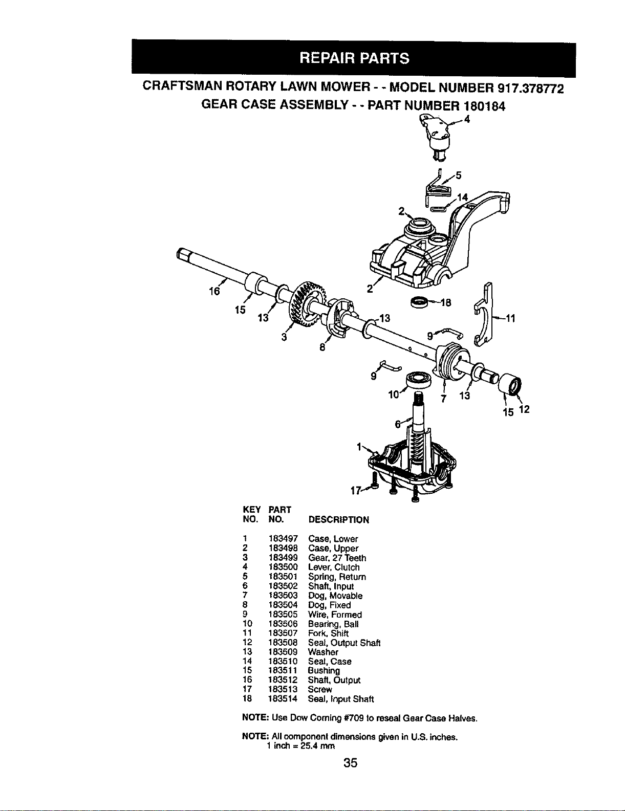
CRAFTSMAN ROTARYLAWN MOWER - - MODEL NUMBER 917.378772
GEAR CASE ASSEMBLY - - PART NUMBER 180184
16
15
3
13
15 12
KEY PART
NO. NO. DESCRIPTION
1 183497 Case, Lower
2 183498 Case, Upper
3 183499 Gear, 27 Teeth
4 183500 Lever,Clutch
5 183501 Spring, Return
6 183502 Shaft, Input
7 183503 Dog, Movable
8 183504 Dog, Fixed
9 183505 Wire, Formed
10 183506 Bearing, Ball
11 183507 Fork, Shift
12 183508 Seal, Output Shaft
13 183509 Washer
14 183510 Seal, Case
15 183511 Bushing
16 183512 Shaft, Output
17 183513 Screw
18 183514 Seal, Input Shaft
NOTE: Use Dow Coming #709 lo reseal Gear Case Halves.
NOTE: All component dimensions given in U.S. inches.
1inch = 25.4 mm
35
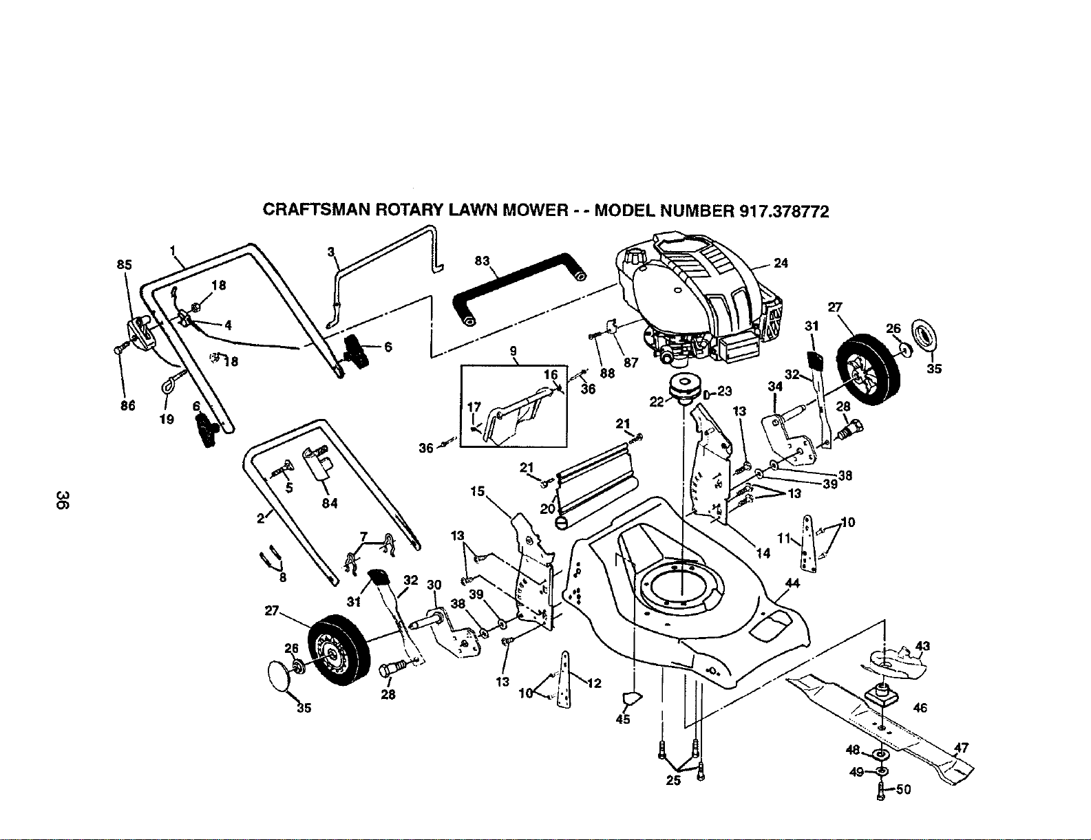
CRAFTSMAN ROTARY LAWN MOWER - - MODEL NUMBER 917.378772
85
86
19
8
84
7
31
28
21
15
88
21
13
30
45
25
31
\
27
26
35
46
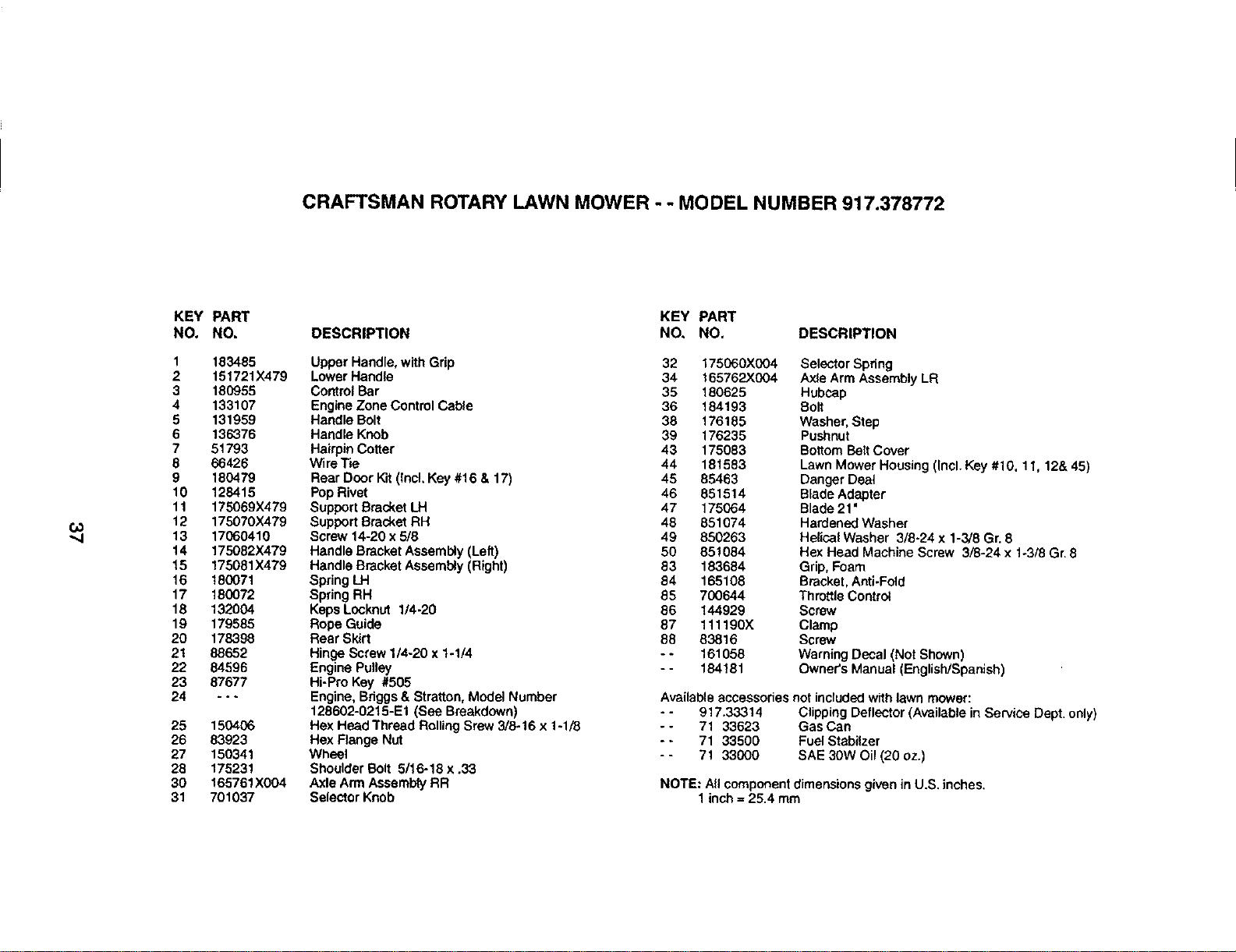
CRAFTSMAN ROTARY LAWN MOWER - - MODEL NUMBER 917.378772
KEY
NO.
1
2
3
4
5
6
7
8
9
10
11
12
13
14
15
16
17
18
19
2O
21
22
23
24
25
26
27
28
30
31
PART
NO.
183485
151721X479
180955
133107
131959
136376
51793
66426
180479
128415
175069X479
175070X479
17060410
175082)(479
175081)(479
180071
180072
132004
179585
178398
88652
84596
87677
.°_
150406
83923
150341
175231
165761X004
701037
KEY PART
DESCRIPTION NO, NO. DESCRIPTION
Upper Handle, with Grip
Lower Handle
ControlBar
Engine Zone Control Cable
Handle Bolt
Handle Knob
HairpinCotter
Wire Tie
Rear Door Kit(Incl. Key #16 & 17)
Pop Rivet
Support Bracket LH
Support Bracket RH
Screw 14-20 x 5/8
Handle Bracket Assembly (Left)
Handle Bracket Assembly (Right)
Spring LH
Spring RH
Keps Locknut 1/4-20
Rope Guide
Rear Skirt
Hinge Screw 1/4-20 x 1-1/4
Engine Pulley
Hi-Pro Key #505
Engine, Bdggs& Stratton, Model Number
128602-0215-E1 (See Breakdown)
Hex Head Thread Rolling Srew 3/8-16 x 1-1/8
Hex Flange Nut
Wheel
Shoulder Bolt 5/16-18 x .33
Axle Arm AssemblyRR
Selector Knob
32 175000X004 Selector Spring
34 165762)(004 Axle Arm Assembly LR
35 180625 Hubcap
36 184193 Bolt
38 176185 Washer, Step
39 176235 Pushnut
43 175083 BottomBait Cover
44 181583 Lawn Mower Housing (Incl. Key #10, 11, 12& 45)
45 85463 Danger Dea_
46 851514 Blade Adapter
47 175064 Blade 21'
48 851074 Hardened Washer
49 850263 Helical Washer 3/6o24 x 1-3/8 Gr. 8
50 85!084 Hex Head Machine Screw 3/8-24 x 1-3/8 Gr. 8
83 183684 Grip, Foam
84 165108 Bracket, Anti-Fold
85 700644 Throttle Control
86 144929 Screw
87 111190X Clamp
88 83816 Screw
- - 161058 Warning Decal (Not Shown)
- - 184181 Owner's Manual (English/Spanlsh)
Available accessoriesnot includedwith lawn mower:
- - 917.33314 Clipping Deflector (Available in Service Dept. only)
-- 71 33623 Gas Can
- - 71 33500 Fuel Stabilzer
- - 71 33000 SAE 30W Oil (20 oz.)
NOTE: All componentdimensions given in U.S. inches.
1inch = 25.4 mm
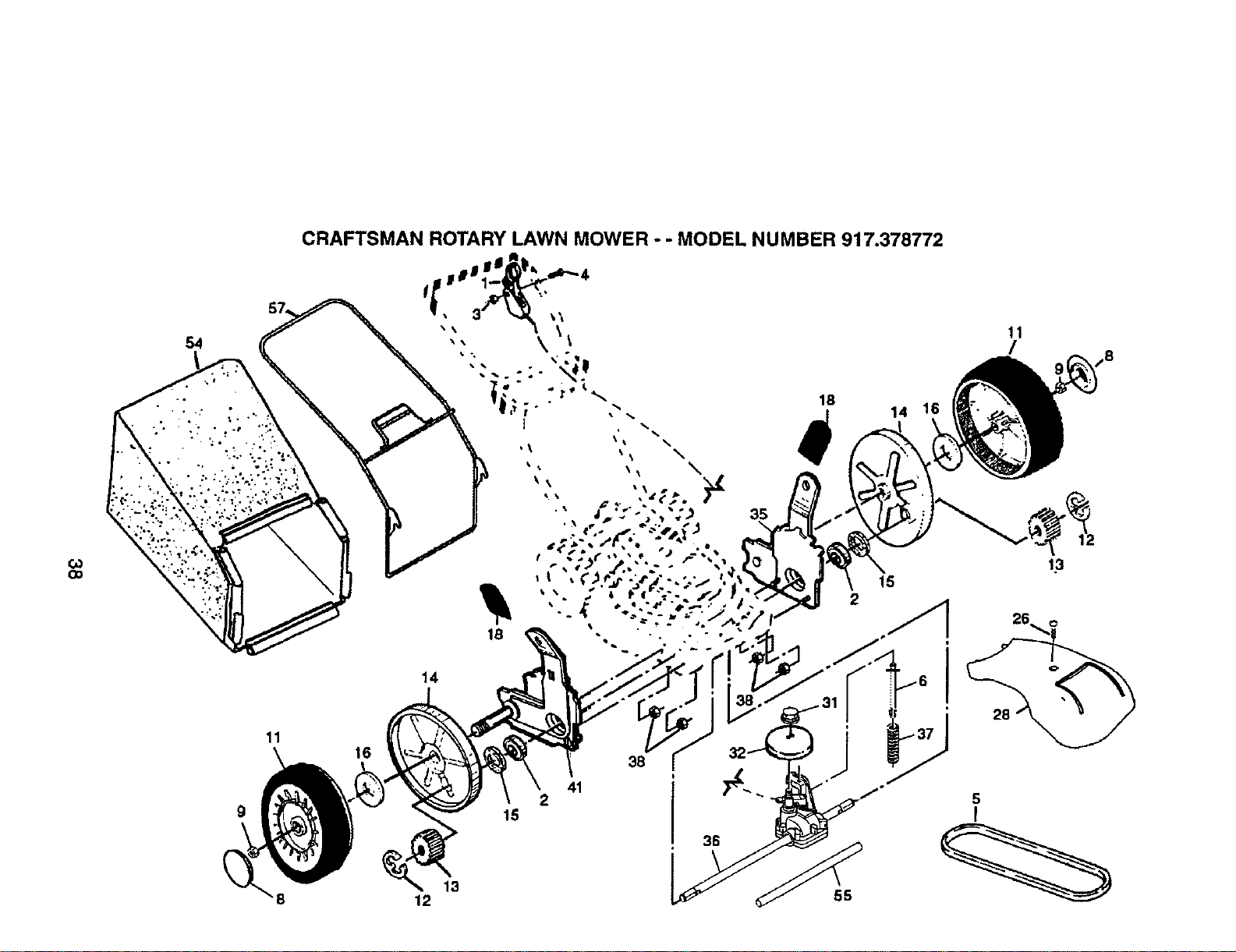
oo
54
11
CRAFTSMAN ROTARY LAWN MOWER - - MODEL NUMBER 917.378772
16
18
35
\
14
41
2
15
14
15
2
13
12
11
/
28
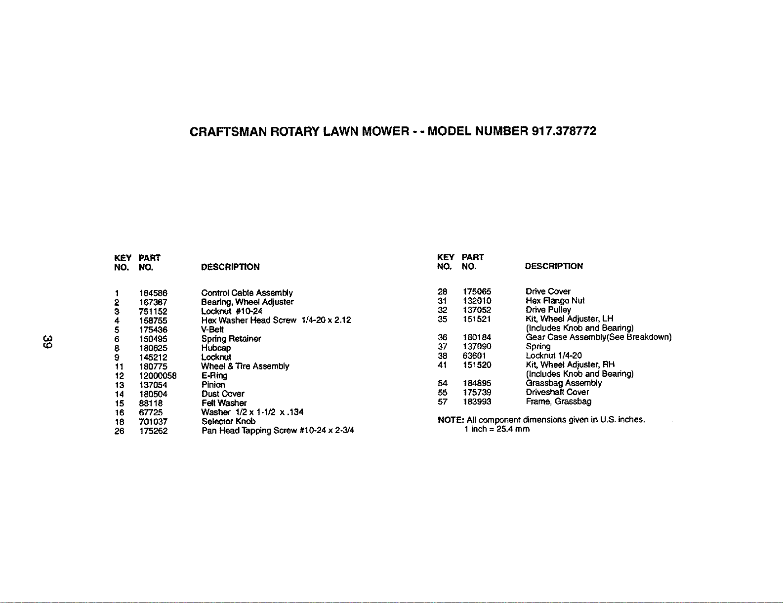
CRAFTSMAN ROTARY LAWN MOWER - - MODEL NUMBER 917.378772
KEY PART
NO. NO.
KEY PART
DESCRIPllON NO. NO, DESCRIPTION
t.O
(O
1
2
3
4
5
6
8
9
11
12
13
14
15
16
18
26
184586
167387
751152
158755
175436
150495
180625
145212
180775
12000058
137054
180504
88118
67725
701037
175262
Control Cable Assembly 28 175065
Bearing, Wheel Adjuster 31 132010
Locknut #10-24 32 137052
Hex Washer Head Screw 1/4-20 x 2.12 35 151521
V-Belt
Spdng Retainer 36 180184
Hubcap 37 137090
Locknut 38 63601
Wheel &TIre Assembly 41 151520
E-Ring
Pinio_ 54 184895
Dust Cover 55 175739
FeltWasher 57 183993
Washer 1/2x 1-1/2 x.134
Selector Knob
Pan Head TappingScrew #10.-24x 2-3/4
Ddve Cover
Hex Range Nut
Drive Pulley
Kit,Wheel Adjuster,LH
(Includes Knoband Beedng)
Gear Case Assembly(See Breakdown
Spdng
Locknut 1/4-20
Kit, Wheel Adjuster, RH
(Includes Knob and Beadng)
Grassbag Assembly
Driveshaft Cover
Frame, Grassbag
NOTE: All component dimensionsgivenin U.S. inches.
1 inch = 25.4 mm
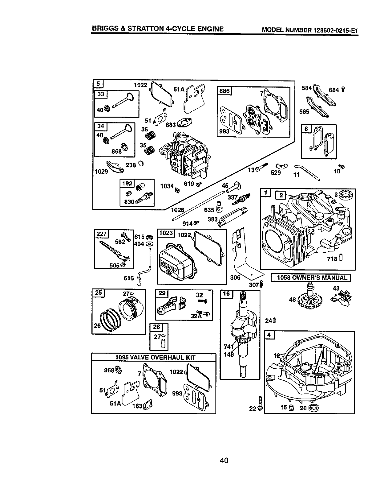
BRIGGS & STRATTON 4-CYCLE ENGINE MODEL NUMBER 128602-0215-E1
1034_ 619_'
585
s0s_ I J
616 {_
270
914_'
3_
SlA 3
741'
718 0
I lossOWNER'SMANUALI
24_
ls_ 2o@
4O
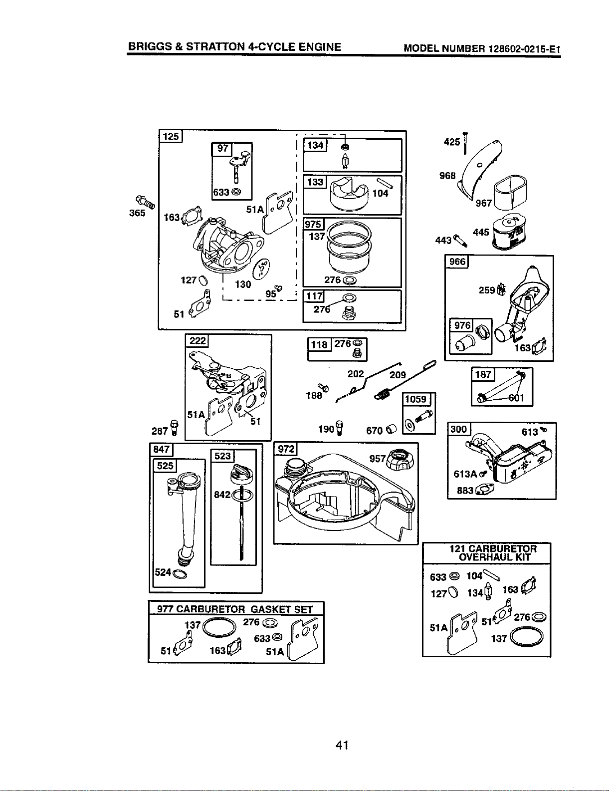
BRIGGS & STRATTON 4-CYCLE ENGINE MODEL NUMBER 128602-0215-E1
287
163__ 51 ! 137_
127_ 130 2760
842(_=_
524 0
_..J 276
202 209
190 _ 670 _
977 CARBURETOR GASKET SET
51 _,.,._j 1631,__ 51A_/j
968 _967
443% 445
I
883_
121 CARBURETOR
OVERHAUL KIT
633 _ 104€:_ ._
127_ 134[_ 163_
41
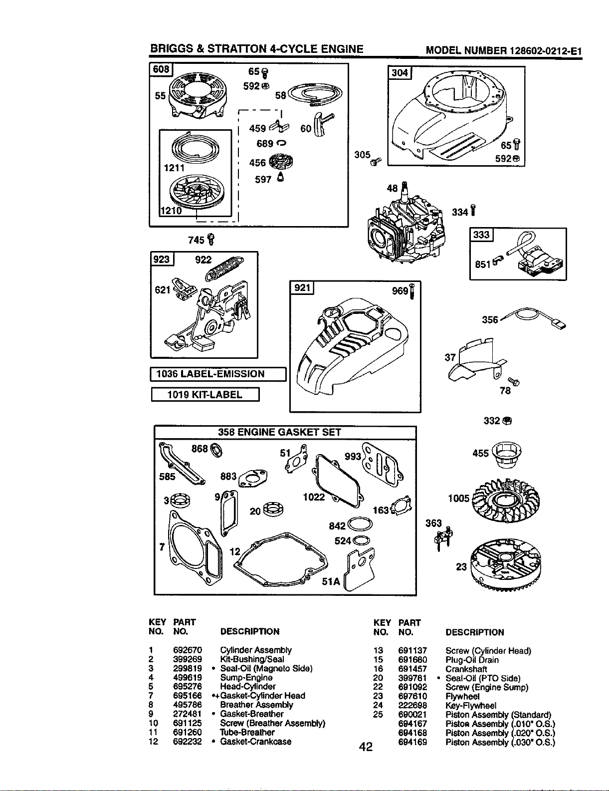
BRIGGS & STRATrON 4-CYCLE ENGINE
745
1036 LABEL-EMISSION
I 1019KIT-LABELI
305_
48
358 ENGINE GASKET SET
842©
MODEL NUMBER 128602-0212-E1
592_
334
78
332
455
1005
KEY PART KEY PART
NO. NO. DESCRIPTION NO. NO.
1 692670 CylinderAssembly 13 691137
2 399269 Kit-Bushing/Seal 15 691680
3 299819 • Seal-Oil (Magneto Bide) 16 691457
4 499619 Bump-Engine 20 399781
5 695276 Head-Cylinder 22 691092
7 695166 *+Gasket-Cylinder Head 23 697610
8 495786 BreatherAssembly 24 222698
9 272481 • Gasket-Breather 25 690021
10 691125 Screw (Breather Assembly) 694167
11 691260 Tube-Breather 694168
12 692232 • Geaket-Crankcase 42 694169
DESCRIPTION
Screw (Cylinder Head)
Plug-OilDrain
Crankshaft
• Seal-Oil (PTO Side)
Screw (Engine Bump)
Flywheel
Key-Rywheel
PistonAssembly (Standard)
Pistca Assembly (.010" O.B.)
PistonAssembly(.020 =O.S.)
PistonAssembly(.030" O.S.)

BRIGGS & STRATTON 4-CYCLE ENGINE MODEL NUMBER 128602-0215-E1
KEY PART
NO. NO. DESCRIPTION
26 499631 RingSet-Piston (Standard)
692785 Ring Set-Piston (.010" O.S,)
692786 Ring Set-Piston (.020" O.S,)
692787 Ring Set-Piston (.030" O.S.)
27 691866 Lock-PistonPin
28 499423 Pin-Piston
29 499424 Rod.Connecting
32 691664 Screw (Connecting Rod)
32A 695759 Screw (Connecting Rod)
33 499642 Valve.Exhaust
34 499641 Va|ve-tntake
35 691304 Spring-Valve (Intake)
36 691304 Spring-Valve (Exhaust)
37 694086 Guard-Rywheel
40 6912194 Retainer-VaNe
43 691997 Slinger-Governor/Oil
45 690977 Tappet-Valve
46 694039 Camshaft
48 692745 Short Stock (Replacement Engine
121602-0515-E 1)
51 692668,O:l:+Gasket -Intake
51A 692799,O:l:+Spacer-Carburator
55 691421 Rousing-Rewind Starter
58 692259 Rope-Starter (Cut to Length)
60 281434 GripStader Rope
65 690837 Screw (Rewind Starter)
78 691108 Screw (Flywheel Guard)
95 691636 Screw (Throttle Valve)
97 499682 Shaft-Throttle
104 691242 O Pin-Float Hinge
117 498978 Jet-Main (Standard)
118 498975 Jet.Main (High Altitude)
121 692703 Kit-CarburetorOverhaul
125 694202 Carburetor
127 694468 _ Plug.Welch
130 691203 Valve-Threttle
133 398187 Float.Carburetor
134 398188 OValve-Needle/Seat
137 693981 OSGasket-Roal Bowl
146 690979 Key-Timing
163 691894,_$+GaskeI-Air Cleaner
187 691050 Line.Fuel (Cut to Required Length)
186 691147 Screw (ControlBracket)
190 690940 Screw (Fuel Tank)
192 694543 Bali-Rocker Arm
202 691303 Unk.Mechanical Governor
209 691851 Spring-Governor
222 692617 Bracket-Control
227 690783 Control Lever-Governor
238 691300 Cap-Valve
259 691189 Bracket-Casing Clamp
276 271716 O.l:SealingWasher
287 690940 Screw (Dipstick Tube)
300 697590 Muffler
304 695976 Housing-Blower
305 691108 Screw (Blower Housing)
306 691232 Shield-Cylinder
307 690345 Screw (Cylinder Shield)
332 690662 Nut (F_ywheel)
333 802574 Armature-Magneto
334 691061 Screw (Armature Magneto)
337 692051 Spark Plug
356 692390 Wire-Stop
358 694090 Engine Gasket Set
363 19069 Flywheel Puller
365 691136 Screw (Carburetor)
383 19674 Wrench-Spark Rug
404 690272 Washer (Govemor Crank)
425 690244 Screw (Air Cleaner Cover)
443 690255 Screw (Air Cleaner Primer Base)
445 697029 Filter-Air Cleaner Cartridge
KEY PART
NO. NO. DESCRIPTION
455 695161 Cup-Flywheel
456 692299 Plata-Pawl Friction
459 261505 Pawt-Ratchet
505 231082 Nut (Governor Control Lever)
523 499621 Dipstick
524 692296 • SeaI-DipstickTube
525 495265 Tube-Oipsttck
529 692937 Grommet
562 94852 Bolt (Governor Control Lever)
584 692342 Cover-Breather Passage
585 691879 • Gasket-Breather Passage
592 690800 Nut (Rewind Starter)
597 691696 Screw (Pawl Friction Plate)
601 95162 Clamp-Hose
608 497680 Starter-Rewind
613 691108 Screw(Muffler)
613A 691140 Screw (Muffler)
615 690340 Retainer-Governor Shaft
616 691308 Crank-Governor
619 691108 Screw (Cylinder Head Plate)
621 692310 Switch-Stop
633 691321 _¢SeaI-Throttle Shall
635 66536 Boot*Sparkplug
670 692294 Spacer-Fuel Tank
684 690345 Screw (Breather Passage Cover)
689 691855 Spdng-Fr{ction
719 690959 Pin-Locatlng
741 691830 Gear-Timing
745 691648 Screw (Brake)
830 694544 Stud (Rocker Arm)
842 691031 • SeaI-O Ring (OipstlckTube)
847 692047 Assembly-DipstickJTube
851 493880 TerminaI-Sparkplug
868 692044 ,+Seal*Valve
883 691693 , Gasket-Exhaust
886 696268 Gasket KiFCylinder Head/Plate
914 691108 Screw (Rocker Cover)
921 691465 Cover-Blower Housing
922 692135 Spring-Brake
923 695891 Brake
957 692046 Cap-Fuel Tank
966 690243 Base-Air Cleaner Primer
967 273356 Fiiter-Pre Cleaner
968 691342 Cover-Air Cleaner
969 691138 Screw (Blower Housing Cover)
972 499618 Tank-Fuel
975 493640 BowFF!oat
976 496115 Pdmer-Carburetor
977 692704 Set-Carb*Jretor Gasket
993 694088 -+Gasket-Cylinder Head Plate
1005 691346 Pan-Flywheel
1019 697624 Kit-Label
1022 691890 ,+Gasket-RockerCover
1023 499624 Cover-Rocker Arm
1026 692045 Rod-Push
1029 691230 Arm-Rocker
1034 691343 Guide-Push Rod
1036 696767 Label-Emission
1058 274979 Owner's Manual
1059 692311 Kit-Screw/Washer
1095 694091 Set*Valve Gasket
1210 498144 Assembly-Pulley/Spring (Pulley)
1=211 498144 Assembly-PulleylSp_ing{Spring)
RPM Settings: Low Speed: 1900-2100
High Speed: 3000-3200
• Included in Engine Gasket Set, Key No.358
2_ Included in Carburetc,r Ovmhaut Kit, Key No. 121
.1: Included in CarburetorGasket Set, Key No. 977
+ Included inValve Overhaul Kit, Key No. 1095
NOTE: All component dimensions given in U.S. inches
43 1Inch = 25.4 mm

©Se_s, RoebuckandCo.
114 _M
® Registered Trademark / Trademark / Service Mark ofSears, Roebuck and Co.
TM SM
® Marca Registrada / Mama de Fdbdca / Mama de Sewicio de Seers, Roebuck and Co.
MC lad
Marque de commerce / Marque d_pos_e de Sears, Roebuck and Co.
184181 Rev, 1 10.03.02 BY Printed in U.S,A.

