Loading ...
Loading ...
Loading ...
11
7. Timely recharging of the batteries will help prolong the
batteries' life. You must recharge the battery packs when
you notice a drop in the equipment's power.
IMPORTANT! Never allow the battery packs to become
fully discharged as this will cause irreversible damage to
the batteries.
Charging a Hot or Cold Battery Pack
The green indicator lights on the charger base indicates that
the battery packs' temperatures are outside the charging
range. Once the packs are within the acceptable range, normal
charging will take place and the red light will be continuous.
Hot or cold battery packs may take longer to charge.
Assembly
mWARNING! Do not insert the batteries until assembly is
complete. Failure to comply could result in accidental starting
and serious personal injury.
mWARNING! Before performing any maintenance,
make sure the batteries and the safety key are removed from
the unit. Failure to heed this warning could result in serious
personal injury.
mWARNING! The product must be fully assembled
before operation. Do not use a product that is only partially
assembled or assembled with damaged parts.
NOTE: Before using the mower, follow these instructions to
assemble the handle and grass bag.
Handle Assembly
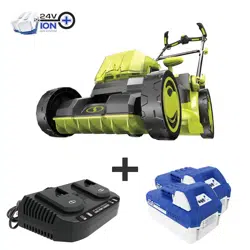
1. The unit arrives with the lower handle in the storage
position and the upper handle detached. Lift the lower
handle to the desired height by aligning the arrow on the
mower body with one of the 3 lines on the latch wheel, as
show (Fig. 4).
NOTE: The lawn mower is equipped with 3 handle
heights, as shown below (Fig. 5).
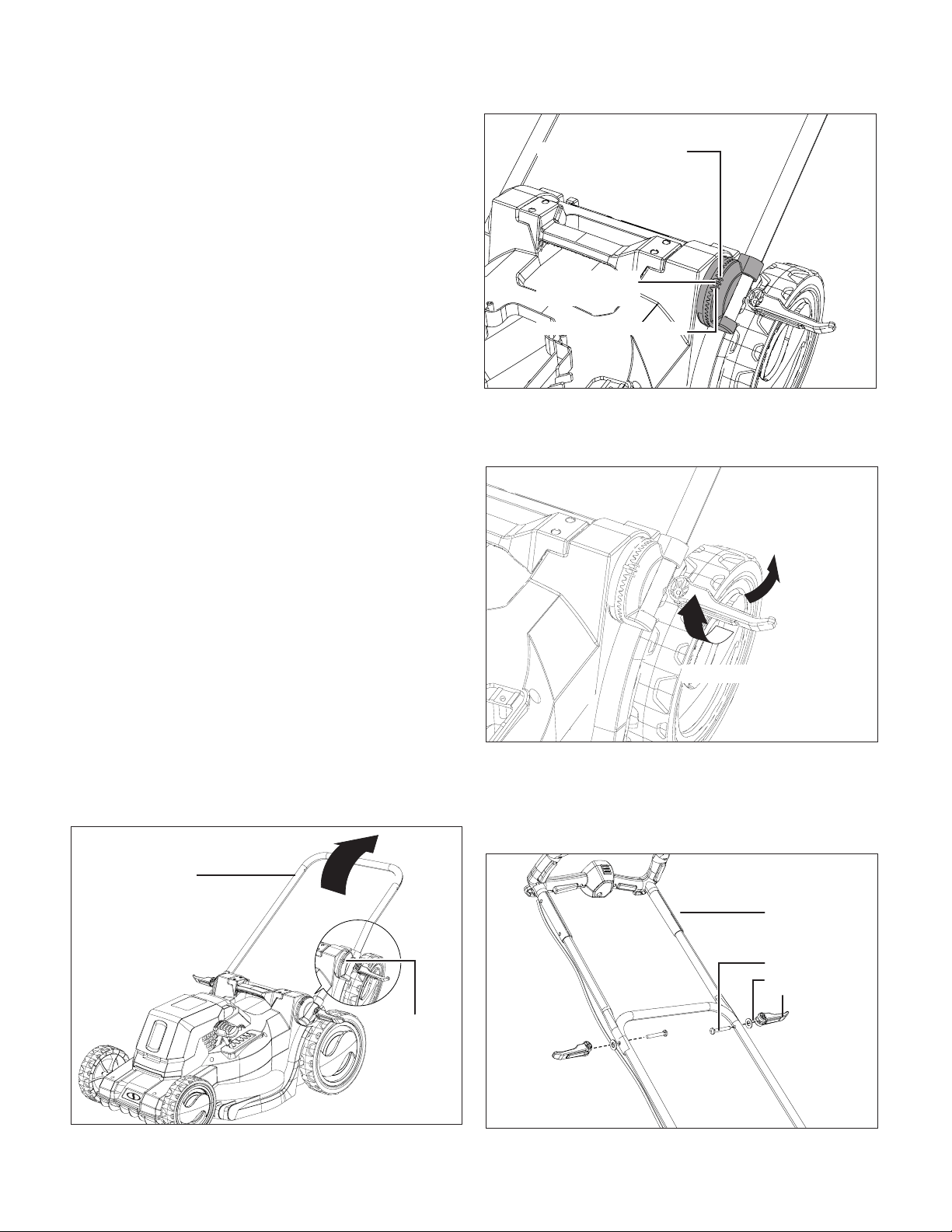
2. When the lower handle frame is set in the desired position,
turn the latch clockwise and ip it up to lock the lower
handle frame in position (Fig. 6).
3. Fit the upper handle frame onto the lower handle frame.
Insert the provided bolts into the aligned holes on the
frames and secure with the washers and the latches (Fig.
7). Screw and ip up the latches to lock the handle frames
in position.
Fig. 4
Align the
mark with
one of the
lines
Lower handle
frame
Fig. 5
High: 44 inch (112 cm)
Middle: 40 inch
(102 cm)
Low: 36 inch (91.5 cm)
Fig. 6
1. Turn clockwise
2. Flip up
Fig. 7
Upper handle
frame
Handle latch
+ washer +
bolt
Loading ...
Loading ...
Loading ...