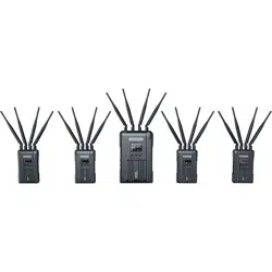

SYSCOM 421S
User Manual
V1.0.0


1
Thank you for purchasing the Hollyland SYSCOM 421S Wireless HD Video
Transmission System. Please read this manual carefully before using the product and
wish you a pleasant experience.
1800ft Transmission Range
The Lowest Achievable Latency without Interference is under 0.1s
5.1-5.9 GHz Band Width, Supports Frequency Configuration for Different Territories
Supports 4 SDI Input and HDMI Input, 4SDI Output and HDMI Output
4 Transmitters Use the Same Wireless Channel with Strong Anti-Interference Ability
Supports TALLY and RS485/RS422 Control
Transmitter Supports 7-36V DC Wide Voltage Input
Receiver Supports 18-36V DC Wide Voltage Input
Stable & Reliable Industrial Metal Case
With RJ45 Interface, Supports Network Pass Through between Transmitter and
Receiver, and Achieves RTSP Pull and Push Streaming
SPECIFIC INFO
KEY FEATURES
FOREWORD
2
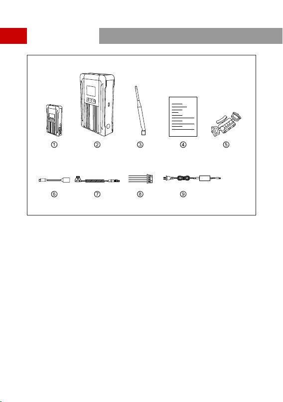
PACKING LIST
x4
①
Transmitter
x1
②
Receiver
x25
③
x1
④
User Guide
5GHz Antenna
x4
⑤
7-Inch Magic Arm
x1
⑥
OTG Cable
x4
⑦
x5
⑧
RS485/RS422 Interface Cable
DC Conversion Cable
x1
⑨
Power Adapter
3
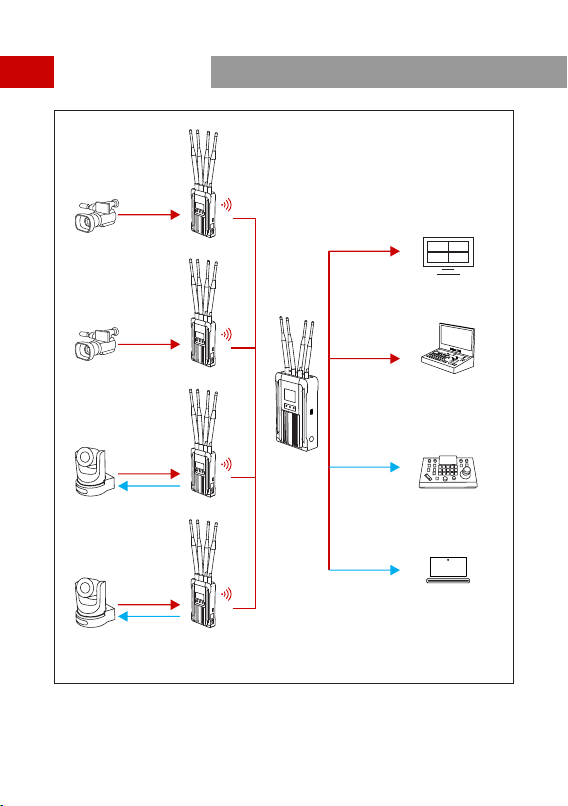
TYPICAL SETUP
1
2
3
4
HDMI/SDI
HDMI/SDI
HDMI/SDI
HDMI/SDI
HDMI/SDI
HDMI/SDI
RS485RS422
LAN
MONITOR
SWITCHBOARD
CAMERA
CONTROLLER
PC
RS485RS422
LAN
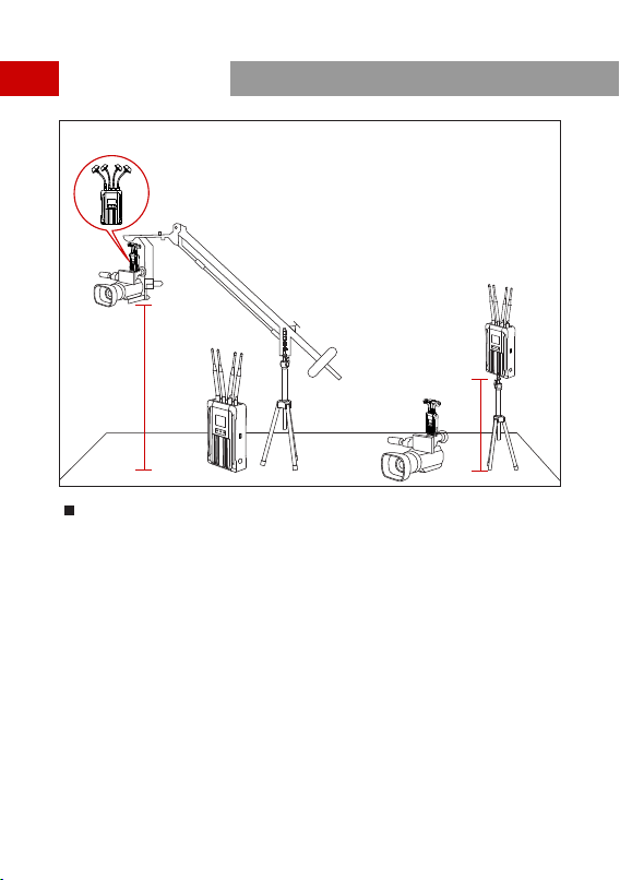
TYPICAL SETUP
2M
10M
Enhancing stability performance of the system, it is recommended to use
mushroom antennas (optional accessories) when there is a huge height difference
between the transmitter and the receiver.
4
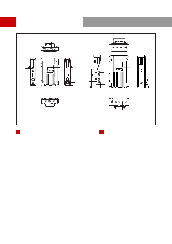
PRODUCT INTERFACES
⑮
⑥
⑬
⑭
A B
⑬
⑫
⑭
①
④
②
③
⑤
⑦
⑩
⑧
⑨
⑤
⑥
④
①
②
③
⑪
⑦
⑩
⑧
⑨
⑪
⑫
①
RP-SMA Antenna Male Interface
②
3- Segment 3.5mm TALLY Output
③
④
HDMI Input
USB Type-C Interface
A
⑤
SDI Input
⑥
DC Power Input
⑦
OLED Display
⑧
UP
⑨
MENU
⑩
DOWN
⑪
RS485/RS422 Interface
⑫
LAN Interface
①
RP-SMA Antenna Male Interface
②
RS485/RS422 Interface
③
④
HDM Output
LAN Interface
B
⑤
SDI Output
⑥
DC Power Input
⑦
TFT Display
⑧
UP
⑨
MENU
⑩
DOWN
⑪
USB Interface
⑫
DC Power Switch
TRANSMITTER RECEIVER
⑬
⑭
⑮
DC Power Switch
1/4-20 Screw Hole
3/8-16 Screw Hole
⑬
⑭
1/4-20 Screw Hole
3/8-16 Screw Hole
5
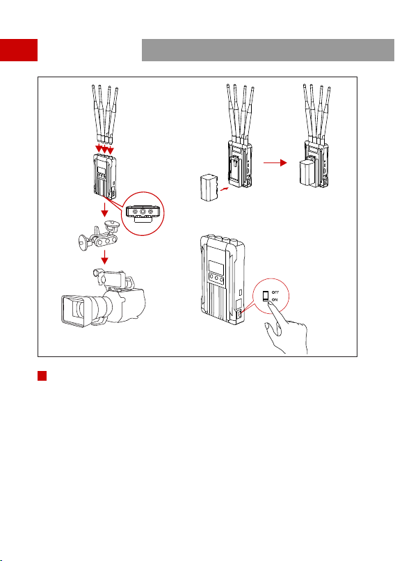
INSTALLATION
①
②
④
③
①
Install antennas on the transmitter as demonstrated.
②
Install magic arm on the 1/4 screw hole at the bottom of transmitter.
③
④
Turn on the device by pressing the power switch to “ON”
Install the batteries (compatible with NP-F970 battery, U60 or the same series) .
TRANSMITTER
6
7
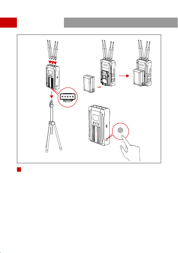
INSTALLATION
ON/OFF
⑤
⑥
⑦
⑧
⑤
Install antennas on the receiver as demonstrated.
⑥
Install on the bracket through the 1/4 screw hole at the bottom of the receiver.
⑦
⑧
Turn on the device by pressing the power switch to “ON”. The power indicator
will show with a blue light.
Install the battery (compatible with V-mount or G-mount large capacity batteries) .
RECEIVER
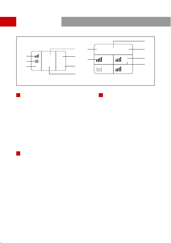
OLED DISPLAY
HLD_2000001
CH2
1
1080P60
3
2
1080P60
4
1080P60
CH2
2
1080P60
HLD_2000001
⑤
④
①
②
①
②
⑤
④
③
③
A B
7.5V
7.5V
NO VIDEO
⑥
⑦
⑥
①
Signal Strength
②
Scene Mode
③
④
Device SSID
Device ID
⑤
Power Supply Voltage
⑥
Video Format
⑦
Channel Display
A
TRANSMITTER
①
Channel Display
②
Signal Strength
③
④
Power Supply Voltage
Device SSID
⑤
Device ID
⑥
Video Format
B
RECEIVER
NOTE: Low Power Indicator: The low power warning will be triggered when the battery
power is too low. And the battery icon will start to blink.
8
9
QUICK GUIDE
Long press the MENU button of the transmitter and receiver to enter the main menu.
ENTER MENU
Press the “UP” or “DOWN” button on the receiver to switch to another channel, press
the “MENU” button to confirm the channel, and the transmitter channel will be
automatically switched.
CHANNEL CHANGE
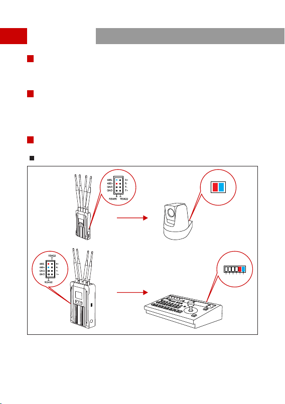
RS485/RS422 INTERFACE USE METHOD
RS485 CONNECTION
+ -
RS485
RS 4 22 RS 4 85
TX+
TX-
RX-
RX+
485-
485+
10
QUICK GUIDE
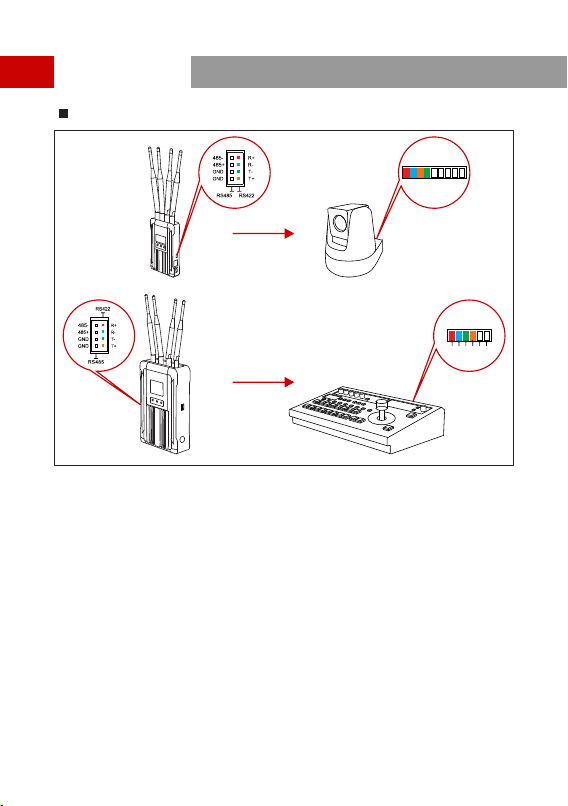
RS422 CONNECTION
1 2
3
4
RS - 42 2/ 485
5
6 7 8 9
RS 4 22 RS 4 85
TX+
TX-
RX-
RX+
485-
485+
1.Connect the transmitter and the receiver with the RS485/RS422 signal cable.
2.As demonstrated above, connect the transmitter with the terminal device and
connect the receiver with the switcher. The line sequence shall correspond to
the colors.
3.Select the corresponding baud rate on both the transmitter and the receiver. (Baud
rate setting path: enter the menu-system setting-serial port setting).
4.The terminal equipment which is connected with the transmitter could be controlled
by the lever arm on the switcher.
11
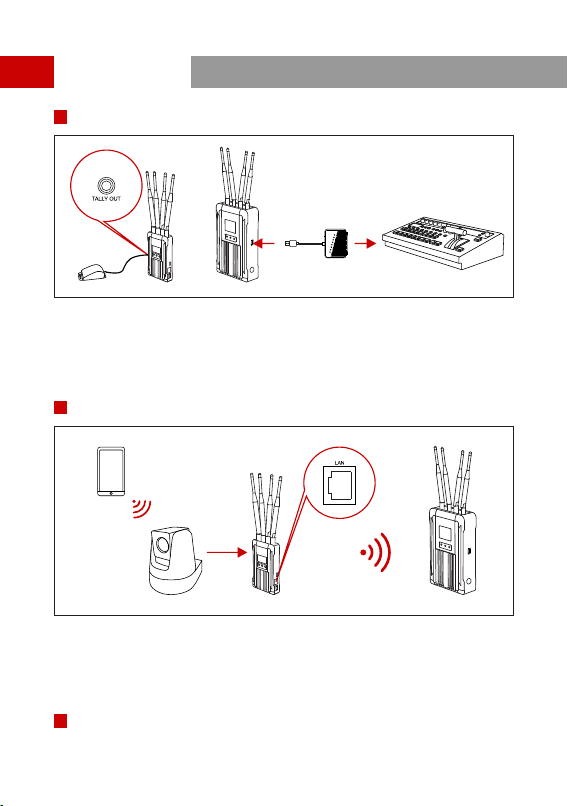
TALLY CONTROL USE METHODS
QUICK GUIDE
1.Connect the TALLY lights to the TALLY out interface on the transmitter.
2.Connect the USB Type-A interface with the TALLY box on the receiver, and connect
the switcher and the TALLY box with a D-Sub Female 25 signal cable.
3.TALLY lights could be controlled by the switches on the switcher.
LAN INTERFACE USE METHOD
1 .Connect the LAN interface of the transmitter to the IP camera through a network
cable, and set the IP network segment to be consistent with the device.
2 .The receiver can pull the stream through the LAN interface, port number: 5554,
account/password: sub/12345678, such as: rtsp://192.168.218.211:5554/sub/123456.
NOTE: THE DEVICE IP IS 192.168.218.X NETWORK SEGMENT

12
PARAMETERS
SDI Input(BNC Female)
HDMI Input(Type A Female)
3.5mm TALLY Output
Antenna Interface*4(RP-SMA Male)
DC Power Input
USB Type-C
LAN
RS485/RS422
SDI Output(BNC Female) *4
HDMI Output (Type A Female) *4
Antenna Interface*4(RP-SMA Male )
DC Power Input
USB Type-A
LAN
RS485/RS422