
OVERVl F POTENTIALHAZARDS
READTHISSAFETYINFORMATI N
Garage doors are large, heavy objects that move with the help of springs under high tension and electric motors. Since moving
objects, springs under tension, and electric motors can cause injuries, your safety and the safety of others depend on the owner or
user of this system to read, understand and implement the information in this manual. Ifyou have questions or do NOT
understandthe information presented, contact The Genie Company or an authorized Genie®Dealer.
The safety alert symbol and following signal words DANGER,WARNING, and CAUTION are used throughout this manual to call
attention to and identify different levels of hazard and special instructions.
,& This is the safety alert symbol. This symbol is placed next to signal words and messages to help you identify
important safety information
The word:
,& DANGER indicates an imminently hazardoussituation which, if NOT avoided,will result in death or serious injury.
,& WARNING indicates a potentially hazardous situation which, if NOT avoided, could result in death or serious injury.
,& CAUTION indicates a potentially hazardous situation which, if NOTavoided, may result in injury or property damage.
The word ,_0 is used to indicate important steps to be followed, important considerations,or location of parts.
IMPORTANTSAFETYINSTRUCTIONS
READAND FOLLOWALL INSTRUCTIONS
SAVETHESE INSTRUCTIONS
POTENTIAL
HAZARD
MOVINGDOOR
ELECTRICAL
SHOCK
HIGH
SPRING
TENSION
PREVENTION
Keep people clear of openingwhile door is moving.
Do NOTallow children to play with the door operator.
Do NOToperate a door that jams or one that has a broken spring.
Turn OFF power before removing operator cover.
When replacing cover, make sure wires are not pinched or near
moving parts.
Operator must be properly grounded.
Do NOTtry to remove, install,repair or adjustsprings or anything to
which door spring parts are fastened, suchas, wood blocks,steel
brackets,cables or other like items.
Installations,repairs and adjustmentsmust be done by a trained door
system technicianusing proper tools and instructions.
PN# 3642036534, 02/26/2010 REV, 1
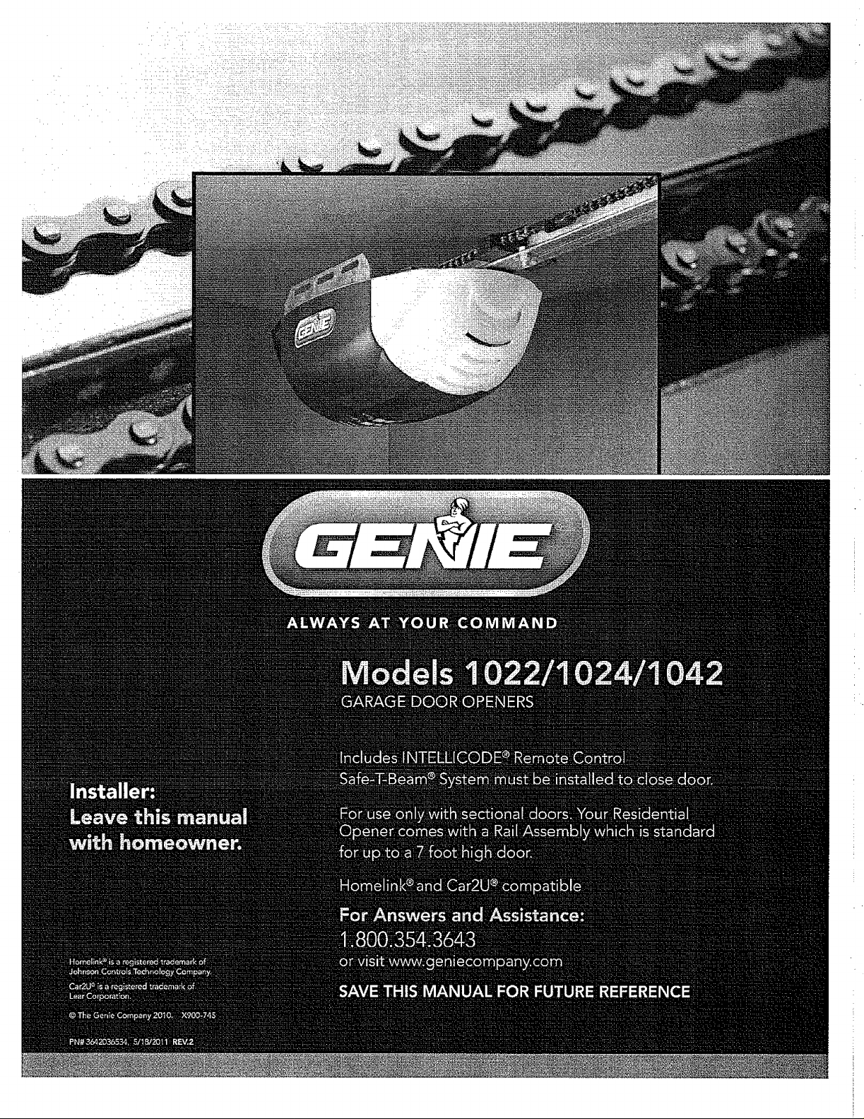
INTELLICODE ® Rolling Code Security System.
An electronic rolling code system that enhances the security of
the door opener by continuously changing the access code
each time the remote control is used. The door opener
responds to each new code only once. An access code copied
from a working system and tried again will not control the door
opener.
Lighted Wall Console*
Operates door opener from inside garage.
(Refer to section 3)
and Car2U ® compatible.
Follow the Homelink ® or Car2U ® instructions in your car
owner's manual.
Safe-T-Beam ® Non-Contact Reversing System**.
Puts an invisible beam across the door opening. The door stops
and reverses to the full open position if anything passes
through the beam. Red or green LED indicator lights on the
power head provide a self diagnostic code if an operational
problem exists. (Refer to Section 10.)
Safe-T-Reverse ®Contact Reversing System.
Automatically stops and reverses a closing door within 2
seconds of contact with an object. (Refer to Section 6.)
Safe-T-Stop ® Timed Reversed System.
Automatically opens a closing door if it fails to close completely
within 30 seconds.
Watch DogTM Monitoring System.
Monitors the Safe=T-Beam@ system to ensure proper function=
ality and will automatically stop and reverse a closing door if a
problem is detected.
Automatic Lighting System.
One bulb lighting supplies up to 75 watts of light for safer
evening exits and entries. Turns ON when door is activated and
automatically turns OFF 3 minutes later.
Manual Emergency Release.
Manually releases door from door opener. Use during a power
failure or other emergency to allow manual opening and closing
of door. (Refer to Section 6.)
PN# 3642036534, 02/26/2010 REV. 1 3
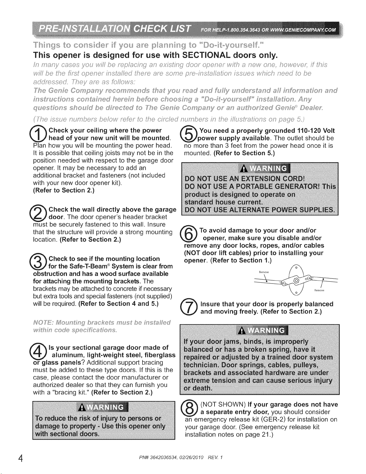
Check your ceiling where the power
head of your new unit will be mounted.
Plan how you will be mounting the power head.
It is possible that ceiling joists may not be in the
position needed with respect to the garage door
opener. It may be necessary to add an
additional bracket and fasteners (not included
with your new door opener kit).
(Refer to Section 2.)
You need a properly grounded 110-120 Volt
power supply available. The outlet should be
no more than 3 feet from the power head once it is
mounted. (Refer to Section 5.)
Check the wall directly above the garage
door. The door opener's header bracket
must be securely fastened to this wall. Insure
that the structure will provide a strong mounting
location. (Refer to Section 2.)
Check to see if the mounting location
for the Safe-T-Beam ®System is clear from
obstruction and has a wood surface available
for attaching the mounting brackets. The
brackets may be attached to concrete if necessary
but extra tools and special fasteners (not supplied)
will be required. (Refer to Section 4 and 5.)
_z_t_,:_ code specifications
To avoid damage to your door and/or
opener, make sure you disable and/or
remove any door locks, ropes, and/or cables
(NOT door lift cables) prior to installing your
opener. (Refer to Section 1.)
insure that your door is properly balanced
and moving freely. (Refer to Section 2.)
is your sectional garage door made of
aluminum, light-weight steel, fiberglass
or glass panels? Additional support bracing
must be added to these type doors. If this is the
case, please contact the door manufacturer or
authorized dealer so that they can furnish you
with a "bracing kit." (Refer to Section 2.)
(NOT SHOWN) If your garage does not have
a separate entry door, you should consider
an emergency release kit (GER-2) for installation on
your garage door. (See emergency release kit
installation notes on page 21.)
PN# 3642036534, 02/26/2010 REV. 1
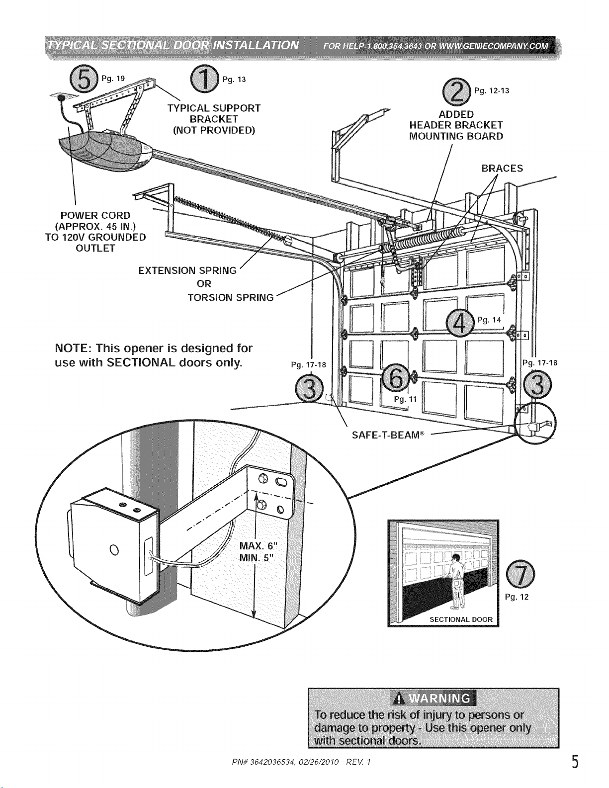
Pg. 13
TYPICAL SUPPORT
BRACKET
(NOT PROVIDED)
Pg. 12-13
ADDED
HEADER BRACKET
MOUNTING BOARD
BRACES
POWER CORD
(APPROX. 45 IN.)
TO 120V GROUNDED
OUTLET
EXTENSION SPRING
OR
TORSION SPRING
NOTE: This opener is designed for
use with SECTIONAL doors only.
Pg. 17-18
MIN. 5
SAFE-T-BEAM _
SECTIONAL DOOR
Pg. 17-18
Pg. 12
PN# 3642036534, 02/26/2010 REV. 1 5
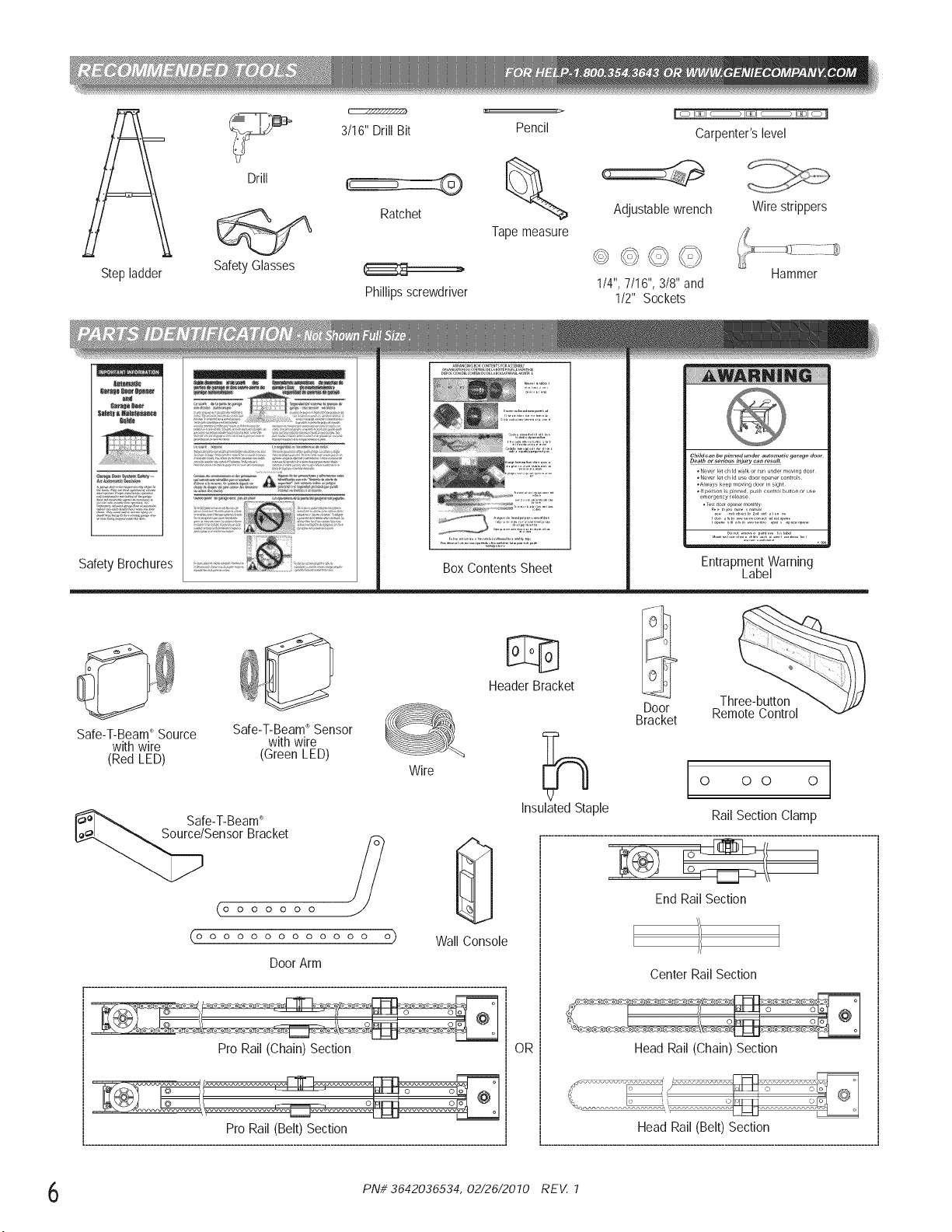
Step ladder
Drill
Safety Glasses
3/16" Drill Bit
Ratchet
Phillipsscrewdriver
Pencil
Tapemeasure
Carpenter'slevel
Adjustablewrench
Wire strippers
1/4",7/16", 3/8" and
1/2" Sockets
Hammer
Safety Brochures
AN
ARRA.GI.G_×CO.TE.TSrORASSe,,B_
Child can be pinned under automatic 9arage door
Dea*hor _eriou_ injury can re_ul_
°Neverle_ch Id walkor ,un undermovingdoor¸
°Newt le_ch Id us_ doo,opener contTol_
°AIway_ke_p movingdoor_n_ght
°. pe,son_sp_n_d pushcontrolbu_onorus_
_mergency,e_ease
Te_,_oorol,_n_rmonthly¸
_o _ ................. _o_o_
..........°:n::::'X_,::':r:i:,__o_o.__'r4.........
Entrapment Warning
Label
Safe-T-Beam_Source Safe-T-Beam_ Sensor
with wire with wire
(Red LED) (Green LED)
Wire
Safe-T-Beam_
Sensor Bracket
0000000
0000000000000
DoorArm
o) Wall Console
,- .......................................................................................................................................
Pro Rail (Chain) Section
Header Bracket
OR
Three-button
Door Remote Control
Bracket
Center Rail Section
,/
Head Rail (Chain) Section
PNi/3642036534, 02/26/2010 REV. 1
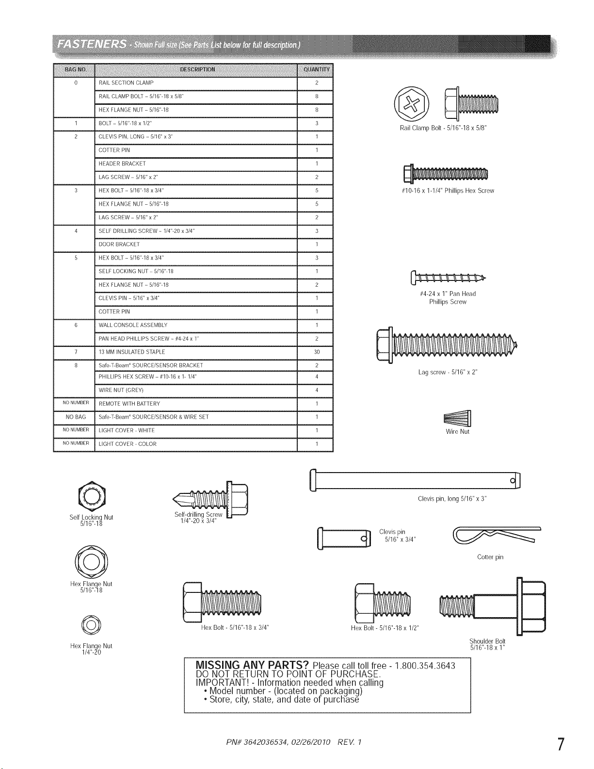
0 RAIL SECIlON CLAMP 2
RAIL CLAMP BOLT - 5/16"-18 x 5/8" 8
HEX FLANGE NU1- 5/16"-18 8
1 BOLl - 5/16"-18 x 1/2" 3
2 CLEVIS PiN, LONG ---5/16" x 3" 1
COI1ER PiN 1
L
HEADER BRACKE 1 1
LAG SCREW - 5/16" x 2" 2
3 HEX BOLt - 5/16".18 x 3/4" 5
HEX FLANGE NUi - 5/16"-18 5
LAG SCREW - 5/16" x 2" 2
4 SELF DRILLING SCREW - 1/4"-20 x 3/4" 3
DOOR BRACKE1 1
5 HEX BOLt - 5/16".18 x 3/4" 3
SELF LOCKING NUi - 5/16".18 1
HEX FLANGE NUi - 5/16".18 2
CLEVIS PIN - 5/16" x 3/4" 1
COTiER PIN 1
6 WALL CONSOLE ASSEMBLY 1
PAN HEAD PHILLIPS SCREW - #4.24 x 1" 2
7 13 MM INSULATED STAPLE 30
8 Safe r-Beam _ SOURCE/SENSOR BRACKE 1 2
PHILLIPS HEX SCREW ---#10-16 x 1- 1/4" 4
WIRE NDI (GREY) 4
NONUMBER REMOTE WITH BATTERY 1
NO BAG Safe r-Beam _ SOURCE/SENSOR & WIRE BE1 1
NONUMBER LIGHi COVER - WHITE 1
NONUMBER LIGH1 COVER - COLOR 1
Rail Clamp Bolt - 5/16"-18 x 5/8"
#10-16 x 1-1/4" Phillips Hex Screw
#4-24 x 1" Pan Head
Phillips Screw
Lag screw - 5/16" x 2"
Wire Nut
©
Self Locking Nut
5/16"-18
©
Hex Flange Nut
5/16"-18
©
Hex Flange Nut
1/4"-20
Self-drilling Screw
1/4"-20 x 3/4"
0
Clevis pin, long 5/16" x 3"
C[] Clevis pin
5/16" x 3/4"
Cotter pin
Hex Bolt - 5/16"-18 x 3/4" Hex Bolt - 5/16"-18 x 1/2"
mml
Shoulder Bolt
5/16"-18 x 1"
MISSING ANY PARTS? Please call toll free- 1.800.354.3643
DO NOT RETURN TO POINT OF PURCHASE.
IMPORTANT! - Information needed when calling
, Model number- (located onpackaging)
• Store, city, state, and date ofpurcHase
PNi/ 3642036534, 02/26/2010 REV. 1 7
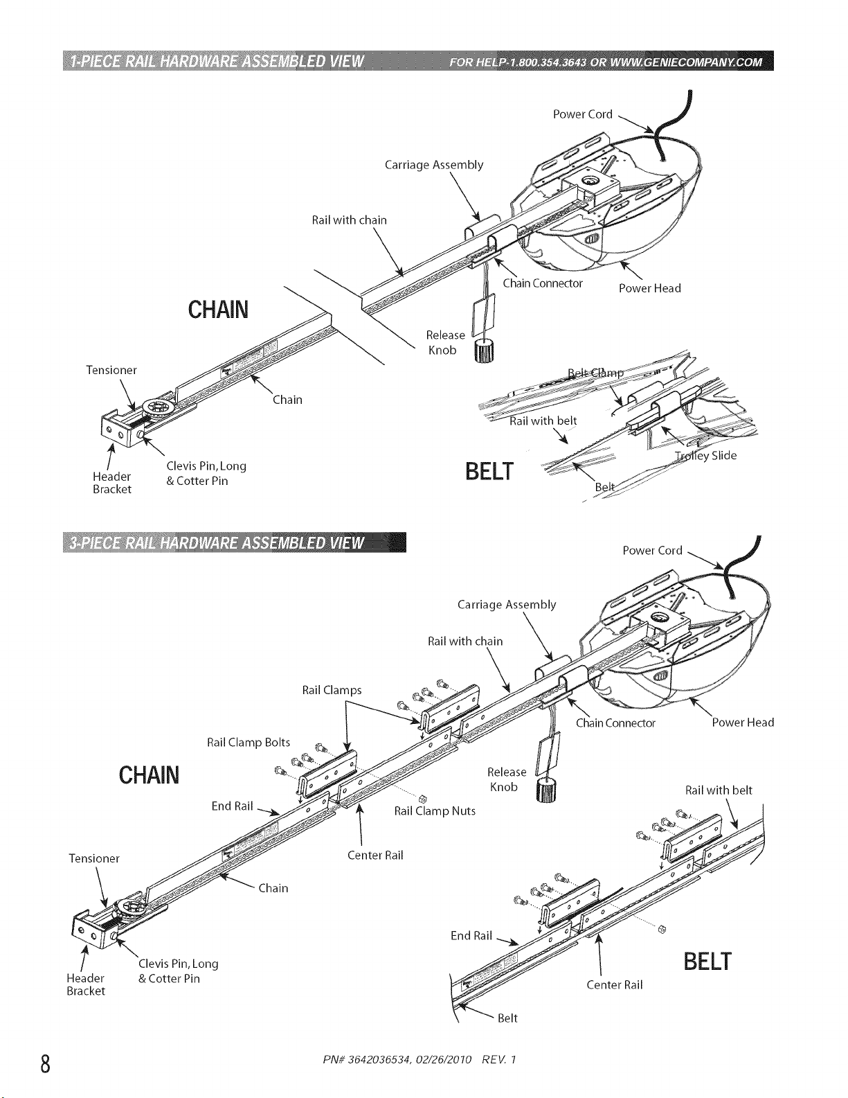
Power Cord
Carriage Assembly
Rail with chain
Tensioner
t
Header
Bracket
CHAIN
Clevis Pin, Long
& Cotter Pin
Chain
Chain Connector Power H ea d
Power Cord
Carriage Assembly
CHAIN
Rail Clamp Bolts
End Rail
Tensioner
Chain
Header
Bracket
Clevis Pin, Long
& Cotter Pin
Rail Clamps
Rail with chain
\
Chain Connector Power Head
--...
Rail Clamp Nuts
Center Rail
Release
Knob Rail with belt
_ _,. __
S
_Belt Center Rail
BELT
PNi/3642036534, 02/26/2010 REV. 1
IMPORTANTiNSTALLATiONiNSTRUCTiONS
1. READAND FOLLOW ALL SAFETY, INSTALLATION 5.
AND OPERATION INSTRUCTIONS.f v:_
d n_i nd_)nd_n 6.
,:: ,::....... , >' ........ ,:: <) D:,
2. Install only on a properly balanced sectional garage door.
An improperly balanced door could cause severe injury.
Have a trained door system technician make repairs or
adjustments to cables, spring assemblies, and other 7.
hardware before installing the opener.
3. Removeall ropesand removeor makeinoperativeall
locksconnectedto the garagedoor beforeinstallingopener.
4. Where possible,installthe door opener7 feet or more 8.
above the floor.For productshavingan emergency
release, mount the emergency release within reach, but at
least6 feet above the floor and avoiding contactwith
vehicles to avoid accidental release.
Do NOT connect the opener to source of power
until instructed to do so.
Locate the control button:
. Within sight of door,
. At minimum height of 5 feet so small children are not
able to reach it, and
. Away from all moving parts of the door.
Install the Entrapment WARNING Label next to the Wall
Control button in a prominent location. Install the
Emergency Release Tag on or next to the emergency
release.
After installing the opener, the door must reverse within
2 seconds when it contacts a 1-1/2 inch high object (or a
2 x 4 board laid flat) on the floor.
I
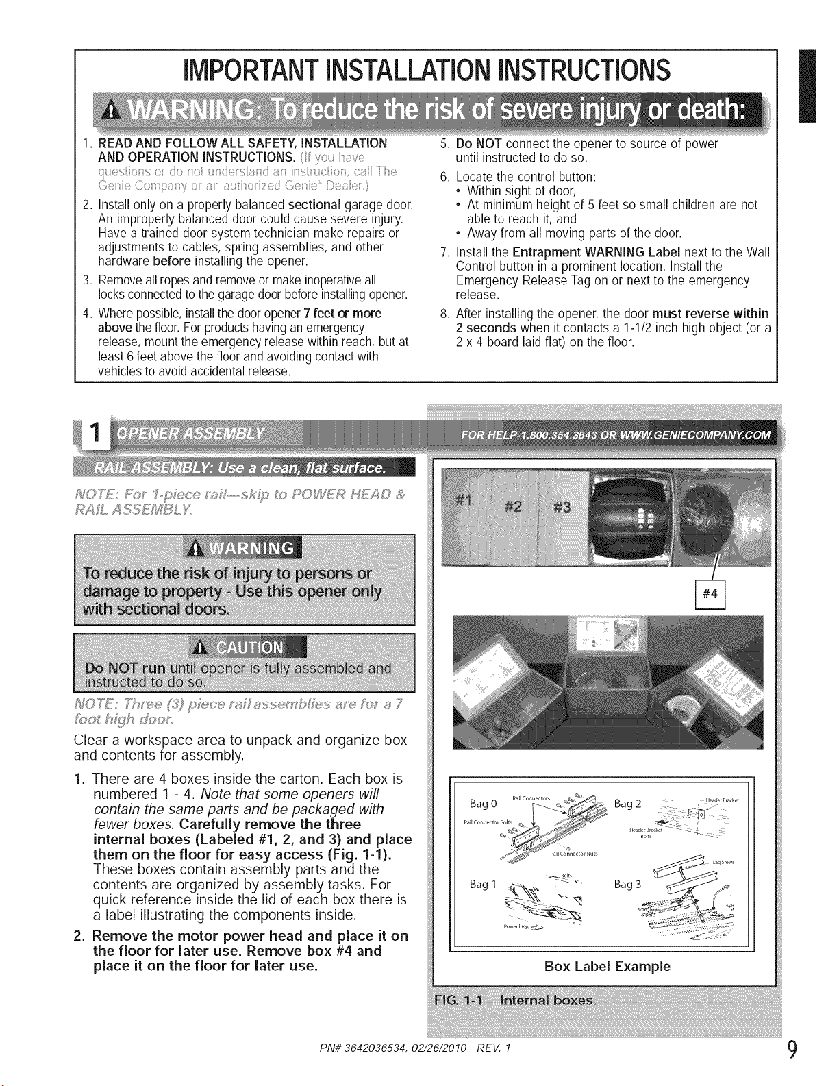
1oo_h}£Jhdoos
Cleara workspaceareatounpackand organizebox
and contentsforassembly.
1. There are 4 boxes inside the carton. Each box is
numbered 1 - 4. Note that some openers will
contain the same parts and be packaged with
fewer boxes. Carefully remove the three
internal boxes (Labeled #1, 2, and 3) and place
them on the floor for easy access (Fig. 1-1).
These boxes contain assembly parts and the
contents are organized by assembly tasks. For
quick reference inside the lid of each box there is
a label illustrating the components inside.
2. Remove the motor power head and place it on
the floor for later use. Remove box #4 and
place it on the floor for later use.
Bag 1
P_w_r h£ad _
Lag Srews
Bag 3 _/
Box Label Example
PN# 3642036534, 02/26/2010 REV. 1 9
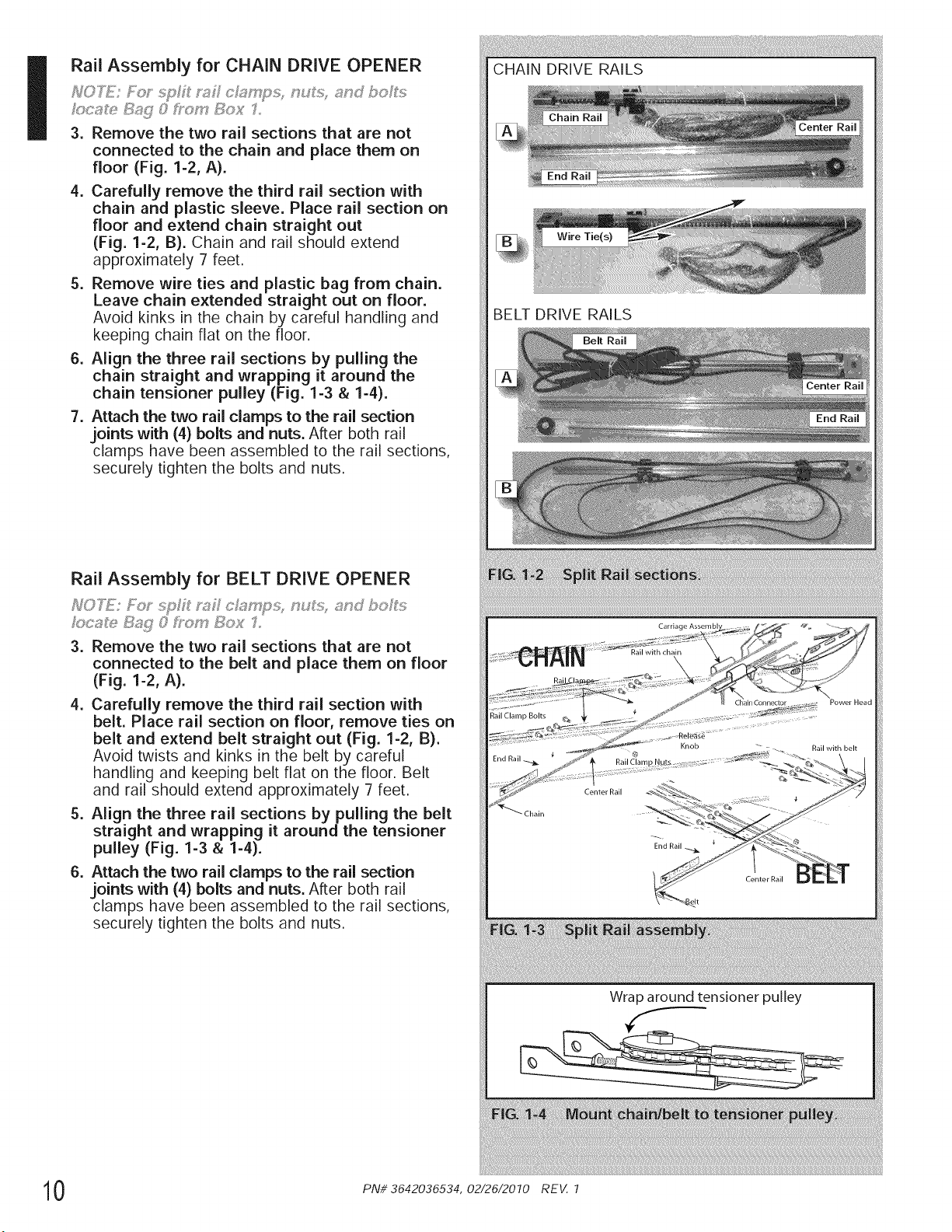
Rail Assembly for CHAIN DRIVE OPENER
3. Remove the two rail sections that are not
connected to the chain and place them on
floor (Fig. 1-2, A).
4. Carefully remove the third rail section with
chain and plastic sleeve. Place rail section on
floor and extend chain straight out
(Fig. 1-2, B). Chain and rail should extend
approximately 7 feet.
5. Remove wire ties and plastic bag from chain.
Leave chain extended straight out on floor.
Avoid kinks in the chain by careful handling and
keeping chain flat on the floor.
6. Align the three rail sections by pulling the
chain straight and wrapping it around the
chain tensioner pulley (Fig. 1-3 & 1-4).
7. Attach the two rail clamps to the rail section
joints with (4) bolts and nuts. After both rail
clamps have been assembled to the rail sections,
securely tighten the bolts and nuts.
Rail Assembly for BELT DRIVE OPENER
3. Remove the two rail sections that are not
connected to the belt and place them on floor
(Fig. 1-2, A).
4. Carefully remove the third rail section with
belt. Place rail section on floor, remove ties on
belt and extend belt straight out (Fig. 1-2, B).
Avoid twists and kinks in the belt by careful
handling and keeping belt flat on the floor. Belt
and rail should extend approximately 7 feet.
5. Align the three rail sections by pulling the belt
straight and wrapping it around the tensioner
pulley (Fig. 1-3 & 1-4).
6. Attach the two rail clamps to the rail section
joints with (4) bolts and nuts. After both rail
clamps have been assembled to the rail sections,
securely tighten the bolts and nuts.
CHAIN DRIVE RAILS
BELT DRIVE RAILS
Belt Rail
Center Rail
Chain
Carriage Assem[ _.
End Rail
Center Rail
Wrap around tensioner pulley
Power Head
Rail with belt
0 PN# 3642036534, 02/26/2010 REV. 1
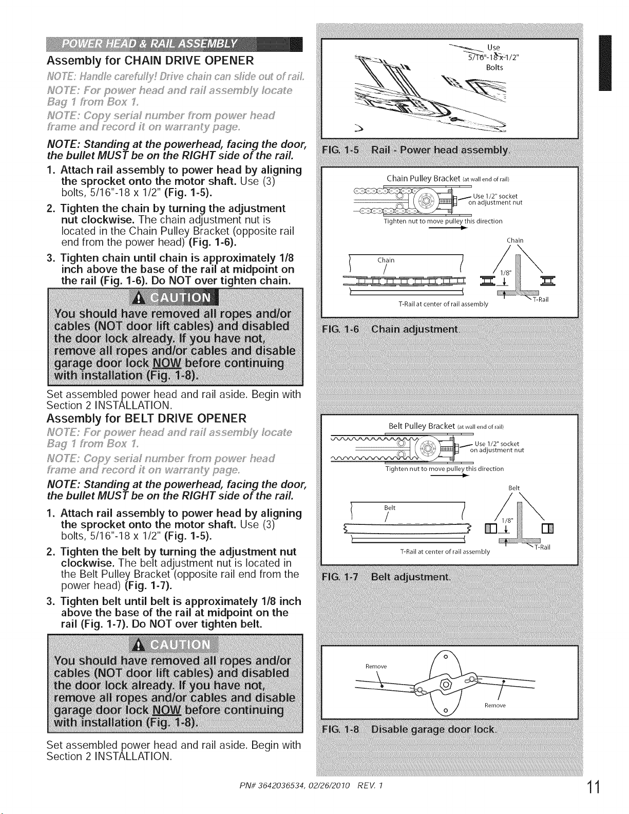
NOTE: Standing at the powerhead, facing the door,
the bullet MUST be on the RIGHT side of the rail.
1. Attach rail assembly to power head by aligning
the sprocket onto the motor shaft. Use (3)
bolts, 5/16"-18 × 1/2" (Fig. 1-5).
2. Tighten the chain by turning the adjustment
nut clockwise. The chain adjustment nut is
located in the Chain Pulley Bracket (opposite rail
end from the power head) (Fig. 1-6).
3. Tighten chain until chain is approximately 1/8
inch above the base of the rail at midpoint on
the rail (Fig. 1-6). Do NOT over tighten chain.
Set assembled power head and rail aside. Begin with
Section 2 INSTALLATION.
Assembly for BELT DRIVE OPENER
_FOTE: seAaF nus*_4_be," _?om po%_?_-head
NOTE: Standing at the powerhead, facing the door,
the bullet MUST be on the RIGHT side of the rail.
1. Attach rail assembly to power head by aligning
the sprocket onto the motor shaft. Use (3)
bolts, 5/16"-18 x 1/2" (Fig. 1-5).
2. Tighten the belt by turning the adjustment nut
clockwise. The belt adjustment nut is located in
the Belt Pulley Bracket (opposite rail end from the
power head) (Fig. 1-7).
3. Tighten belt until belt is approximately 1/8 inch
above the base of the rail at midpoint on the
rail (Fig. 1-7). Do NOT over tighten belt.
Set assembled power head and rail aside. Begin with
Section 2 INSTALLATION.
Chain Pulley Bracket (at wall end of rail)
2-'Ose 1, "soc,et
_, on adjustment nut
Tighten nut to move pulley this direction
Chain
"T-Rail
T-Rail at center of rail assembly
i#iii#i!iiiii#iiiii!i'i_iiii!il¸i_iiii_iiii!i¸ili#iiiiiill¸i_iii!i¸ili#iiiiiill¸i_iii!i¸ili#iiiiiill¸i_iii!i¸ili#iiiiiill¸i_iii!i¸ili#iiiiiill¸i_iii!_ii@i;i_iii!ii!i¸i_i_ii_i_i_i_!ili=i!i!i!i;iiii_iil¸i_iiii!i_i_i#!i_i_i_i_=i_;_ii_i_:_i_i;;_!i!_i!i_!i_i_i_i_!!!!_!_i!;_!!_!_ii:i_i_i_¸IIIII¸_!_ili!_¸i_i_ii_ii;i_i_i_i_ii_i_II!¸II_I¸ii!i_#iiiiii!!iiiiiii!!iiiiiii!!iiiiiii!!iiiiiii!!iii!i!i_ii!#_i_iiiiii¸i_ii#i¸i_iii!i¸ili#iiiiiill¸i_iii!i¸ili#iiiiiill¸i_iii!i¸ili#iiiiiill¸i_iii!i¸ili#iiiiiill¸i_iii!i¸ili#iiiiiill¸i_iii!i¸ili#iiiiiill¸i_iii!i¸ili#iiiiiill¸i_iii!i¸ili#i!i_i!!!#¸i=ili¸i=ili¸i¸i!il
Belt Pulley Bracket (at wall end of rail)
_b,_/Use 1/2" socket
_- I t _\_._/l_d on adjustment nut
Tighten nut to move pulley this direction
Belt
T-Rail at center of rail assembly
Belt
Remove
Remove
"T-Rail
PN# 3642036534, 02/26/2010 REV. 1 1 1
12
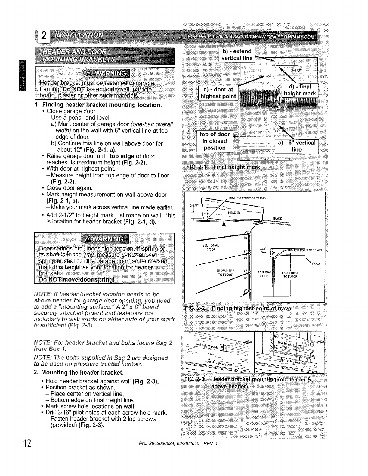
1. Finding header bracket mounting location.
• Close garage door.
-Use a pencil and level.
a) Mark center of garage door (one-half overall
width) on the wall with 6" vertical line at top
edge of door.
b) Continue this line on wall above door for
about 12" (Fig. 2-1, a).
• Raise garage door until top edge of door
reaches its maximum height (Fig, 2-2).
• With door at highest point.
- Measure height from top edge of door to floor
(Fig. 2-2).
• Close door again.
° Mark height measurement on wall above door
(Fig. 2-1, c),
- Make your mark across vertical line made earlier,
° Add 2-1/2' to height mark just made on wall. This
is location for header bracket (Fig. 2-1, d).
NOTE: ff header bracket _ocaZion needs to be
above header for garage door opening, you need
to add a "mounting surface." A 2" x 6" board
securdy adached (board and fasteners not
#ncluded) to waft studs on either side of your mark
is sufficient (Fig. 2o3).
NOTE: For header bracket and bolts locate Bag 2
from Box f.
NOTE: The bol_s supplied in Bag 2 are designed
[o be used on pressure trea_ed lumber.
2. Mounting the header bracket.
• Hold header bracket against wall (Fig. 2-3).
• Position bracket as shown.
- Place center on vertical line,
- Bottom edge on final height line.
° Mark screw hole locations on wall.
• Drill 3/16" pilot holes at each screw hole mark.
- Fasten header bracket with 2 lag screws
(provided) (Fig. 2-3).
b) - extend
vertical line
SECTIONAL
DOOR
FROM HERE
!
il ::
PN# 3642036534, 02/26/20t0 REV !
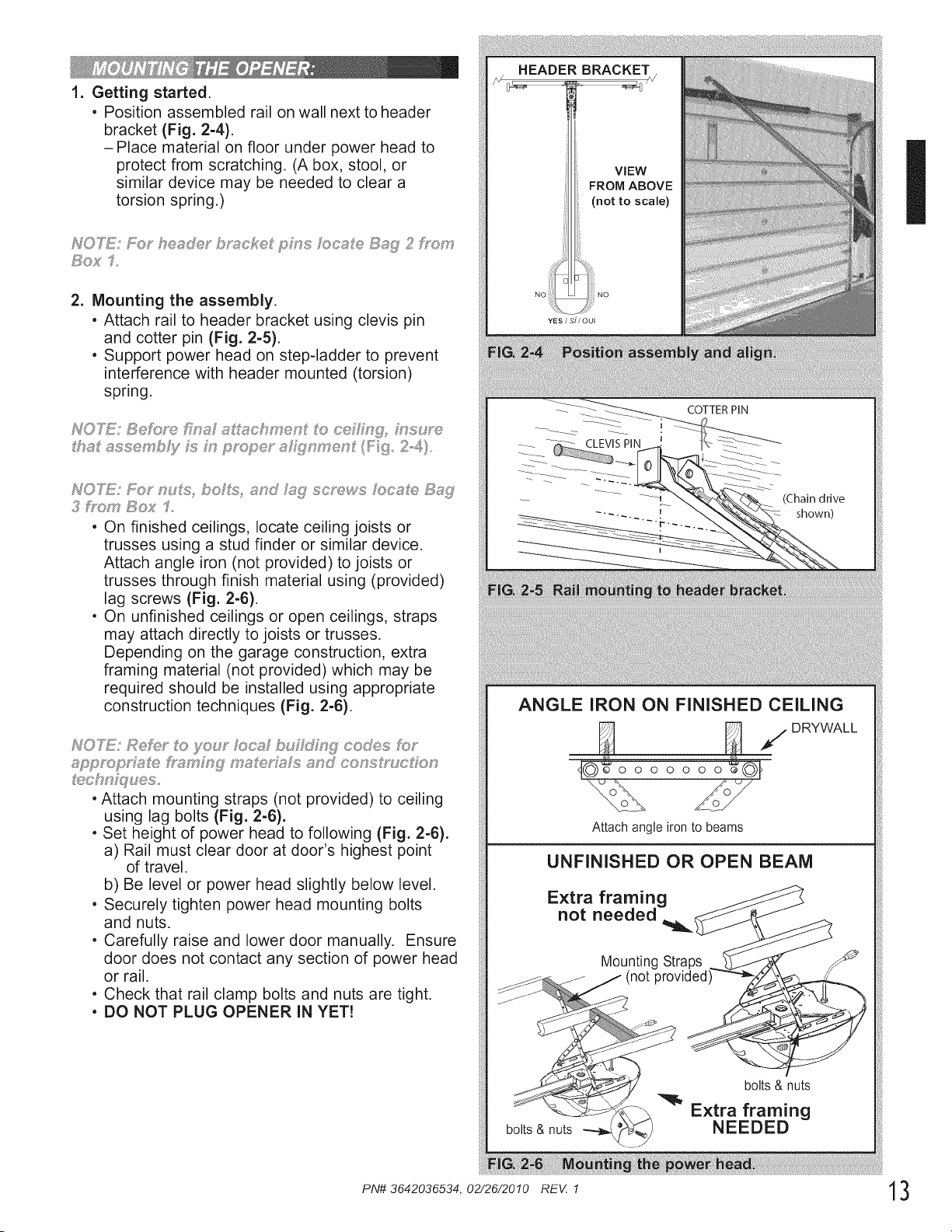
1. Getting started.
, Position assembled rail on wall next to header
bracket (Fig. 2-4).
-Place material on floor under power head to
protect from scratching. (A box, stool, or
similar device may be needed to clear a
torsion spring.)
Sos< 1=
=
Mounting the assembly.
, Attach rail to header bracket using clevis pin
and cotter pin (Fig. 2-5).
, Support power head on step-ladder to prevent
interference with header mounted (torsion)
spring.
NOTE: SeF0_,e [JY?s s schryen ito c®_ng_ ms_: _
ths sssery b?y _:; m pmd;_e_°sh:_i?myen (F: _3 2.-4)
3 _bom Bo:_" I
, On finished ceilings, locate ceiling joists or
trusses using a stud finder or similar device.
Attach angle iron (not provided) to joists or
trusses through finish material using (provided)
lag screws (Fig. 2-6).
, On unfinished ceilings or open ceilings, straps
may attach directly to joists or trusses.
Depending on the garage construction, extra
framing material (not provided) which may be
required should be installed using appropriate
construction techniques (Fig. 2-6).
NOTE: Ref'e _o you Ioc_t bu)i_r_j codes _;1_"
, Attach mounting straps (not provided) to ceiling
using lag bolts (Fig. 2-6).
, Set height of power head to following (Fig. 2-6).
a) Rail must clear door at door's highest point
of travel.
b) Be level or power head slightly below level.
, Securely tighten power head mounting bolts
and nuts.
, Carefully raise and lower door manually. Ensure
door does not contact any section of power head
or rail.
, Check that rail clamp bolts and nuts are tight.
, DO NOT PLUG OPENER IN YET!
COTTER PIN
(Chain drive
shown)
ANGLE IRON ON FINISHED CEILING
_ /DRYWALL
_J©_o o o o o o o£01
Attach angle iron to beams
UNFINISHED OR OPEN BEAM
Extra framing
not needed
Mounting Straps
(not provided
bolts & nuts
bolts & nuts
Extra framing
NEEDED
iJ!iiiii_il_iiiiiiiiii! ii_iii _;!i,l!_!i!_, ;,:i_!_ai,i,!,,,,,!,,i!,
I
uos oc,s, e S_?{;I
fro_, £!;os' 2
I,
2,
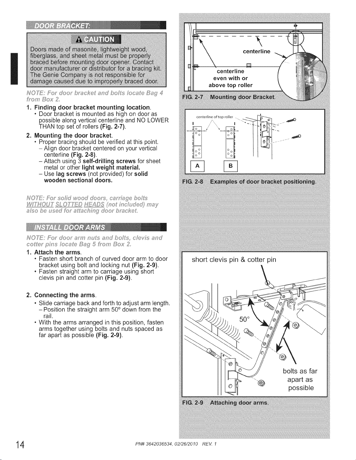
Finding door bracket mounting location.
. Door bracket is mounted as high on door as
possible along vertical centerline and NO LOWER
THAN top set of rollers (Fig. 2-7).
Mounting the door bracket.
• Proper bracing should be verified at this point.
- Align door bracket centered on your vertical
centerline (Fig. 2-8).
- Attach using 3 self-drilling screws for sheet
metal or other light weight material.
- Use lag screws (not provided for solid
wooden sectional doors.
NOICE: _:_;,"door am? nuIs and bo Is, cMds snd
co_/_y piJ?s oca_e Bag 5 i7o_yBox 2
1. Attach the arms.
, Fasten short branch of curved door arm to door
bracket using bolt and locking nut (Fig. 2-9).
, Fasten straight arm to carriage using short
clevis pin and cotter pin (Fig. 2-9).
2. Connecting the arms.
, Slide carriage back and forth to adjust arm length.
-Position the straight arm 50 ° down from the
rail.
, With the arms arranged in this position, fasten
arms together using bolts and nuts spaced as
far apart as possible (Fig. 2-9).
i
short clevis pin & cotter pin
bolts as far
apart as
possible
4 PN# 3642036534, 02/26/2010 REV. 1
NOTE: For 14,9}IfConsole, _,Nreand ,_}suia_d
staples tecate _9-s 6 and 7 Dom Box 2,
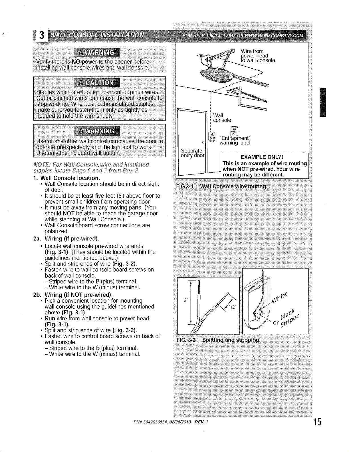
1. Wall Console location.
• Wall Console location should be in direct sight
of door.
- It should be at least five feet (5') above floor to
prevent small children from operating door.
• tt must be away from any moving parts. ('You
should NOT be able to reach the garage door
while standing at Wall Console,)
• Wall Console board screw connections are
polarized.
2a. Wiring (if pre-wired).
• Locate wall console pre-wired wire ends
(Fig. 3-1) (They should be located within the
guidelines mentioned above.)
• Split and strip ends of wire (Fig. 3-2).
• Fasten wire to wall console board screws on
back of wall console.
- Striped wire to the B (plus) terminal.
- White wire to the W (minus) terminal.
2b. Wiring (If NOT pre-wired).
. Pick a convenient location for mounting
wall console using the guidelines mentioned
above (Fig. 3.1).
• Run wire from wall console to power head
(Fig. 3-1).
• Split and strip ends of wire (Fig. 3-2).
• Fasten wire to control board screws on back of
wall console.
- Striped wire to the B (plus) terminal.
- White wire to the W (minus) terminal.
Wire from
_oOWer head
wan console.
Separate
entry door
Wall
console
[_ "Ent_ment'[
warning laDel
___ EXAMPLE ONLY!
This is an example of wire routing
when NOT pre-wired. Your wire
------------ routing may be different.
:_:i:i!'i 7}!7iiii!ii_ii}777!:!i!i;i!ii_ii!_:;iiiii_i?;Ti;ii!':i!i!ii!ili!i_::_!iii7i<i_11!_!!;!!;:_ii!!;!i _:i
::[i_:i: :_]!__i_:!_i[:iii_il :i_:::<IXli ::iii:::i:7:i t[:::::::77: L:_i:::}i',7::i_}it}!tiii t i_!_iT,:t:::::7: :::7i
:i!:::::!<!_i_7:ii_i;iiiiii!ii!iiii_klii_iiiiiiiiTii!i7!i:i7'_!i!:;iiTki_iiii!iii(iiii!iiiii_i:ii:::_;i_ii::i;!:i_;:::i(;i;i!iii
;:! :::}:}i_::i: :_ii !_iiiiiii!iJiiii!ii}ii:!_!i:!iifil!i_;iiiiT!ili¢i!i!ii!':_i_,!i!i__!!!_!!!!;i!;iiiiiii_ii'_itii!tiii!!;!it}
7::7i_;}::ii !'_iiiii!iiT;'Tii}i:i!_iiTi:i iiliihi![!i_i:"!i!iiTii}iTi_!i}iTi}ii i!7_,i,i2}!i_f._t7[7_5i;[!i7,iiiDi_}[ii_;_!iiiiiii._?#
i ::i; i:!:i1177iTiiiiii;iiiililill!i_:i!iiil i_17iiii!iiiTiiii!!!!iiiiii iiii_:_!iiiiT!i!i :_
i)ii)iiiii!Tiiiiili il)
:::_!7 1!i _P!if!!,g _g _ifiPi[_i!' 7: _:_ : ; i
:7:::::::c777:7::{7::;Tt_{{77_TL;f: :7+7{{f{{7{,,777{7f:i{{7]:{_,7 ::::f:7,.Y. 7 {_,i, ,{:7] 7 7.: } 7,{ 7:;+{,;,: 7::7::_: L,7
7:_7777:77i{77!i_!i=,iii!i_ _:_1177f_LT'7_7{{7777]{;{71'7::17777',7_"k;77 7_:7,:7:!77
{:77:{i{:2:{7i_{:{i{'{77{7{7{!{f{7{{:2{}77{{77{{7{{7{7i7f{ {'7:,71f{ 7:7{ 7{777f{ 11{{{{{7{7 {71177{){i77{:{77)27iifir7:j7{
77i:iT:iiTi!!i!i{7i77:17i7777:77::: 777777::7;7;{,:777777 ::7!7i77: 7: :77i-177 i
7}: ;; _i:;:i:il;:_ii!;_!};_ii!i)i!)71;i;'.iDi!7_!!!:ii!it;i;!i;_;_ii!i:_!; i<i;_)i::7_>/:i:{i;ii!!i)!i!ii!i_!)?iii:;i;
7{::]777{!{7 [Z]] [ 7<7{7 ]{]_}{7_'7_77_?777;7777{7?71{__!"7_7!!{7{77(_!{7_7!}!'77{'7"7777_1_7t[YT;{77"7{7"3{:i!_7!7{+}+_77::_}H7!_7_I{72_77{{:777J
I
!_i_ii!ii_i!iii_i_!ii!7iiiiiiiii_iiii_iii_!i_ii7_i_i7i!ii_!!_!_!_!i!iii_i_i_i_i!iii!_iii_iiii_iii!:_!_iii7!_ii_i_7_!iii_ii_ii_!_i_i7i7i_!ii!_ii!i
PAl# 3642036534. 02/26/20t0 REV.. 7 15
i
16
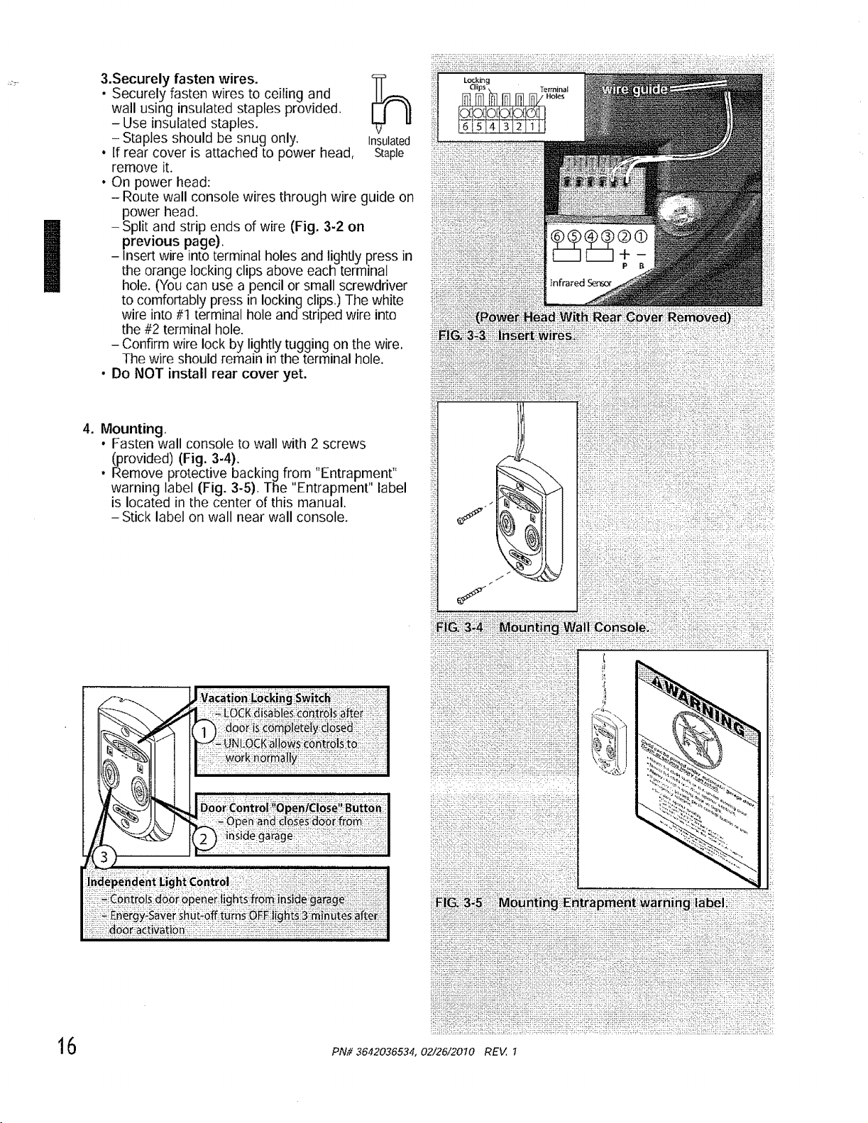
3.Securely fasten wires.
• Securely fasten wires to ceiling and
wall using insulated staples provided.
-Use insulated staples.
- Staples should be snug only. Insulated
• If rear cover is attached to power head, Staple
remove it,
• On power head:
- Route wall console wires through wire guide on
power head.
- Split and strip ends of wire (Fig. 3-2 on
previous page).
-Insert wire into terminal holes and lightly press in
the orange locking clips above each terminal
hole. (You can use a pencil or small screwdriver
to comfortably press in locking clips,) The white
wire into #t terminal hole and striped wire into
the #2 terminal hole.
- Confirm wire lock by lightly tugging on the wire,
The wire should remain in the terminal hole.
• Do NOT install rear cover yet.
4. Mounting,
• Fasten wall console to wall with 2 screws
(provided) (Fig. 3-4).
• Remove protective backing from "Entrapment"
warning label (Fig. 3-5). The "Entrapment" label
is located in the center of this manual.
- Stick label on wall near wall console.
_ii_.E|6_ii_:_3i_ii_i|_e_i._:i_es::_!i_i_ii_iii:i!i!ii!iii_ii:ii_ii_i_ii:_:iii_ii:_ii!_:;!ii!i_ii_:!;1_!!_ti!i_:_ii_::ii;ii!ii
_iii_i!_i_!i_!i!ii_i_i_!i_!iiiiiiiii_ii_ii_i!_ii_i_:ii!i!_i_!?i_iiiii:i_:::iiii!iii!i_i_!i_!_iiiii_ii:i_i:ii_i_!:!i:_i:_i!!i!!!_>_ii_ii_!Ki!:_i_iii:i!
PN# 3642036534, 02/26/2010 REV. I
NOTE: For SaYe-T.BeamC_,screws, _Mre, and
insulated s_ap_es_ocate _,,_:emsa,,d Bag 8 frown Box 3,
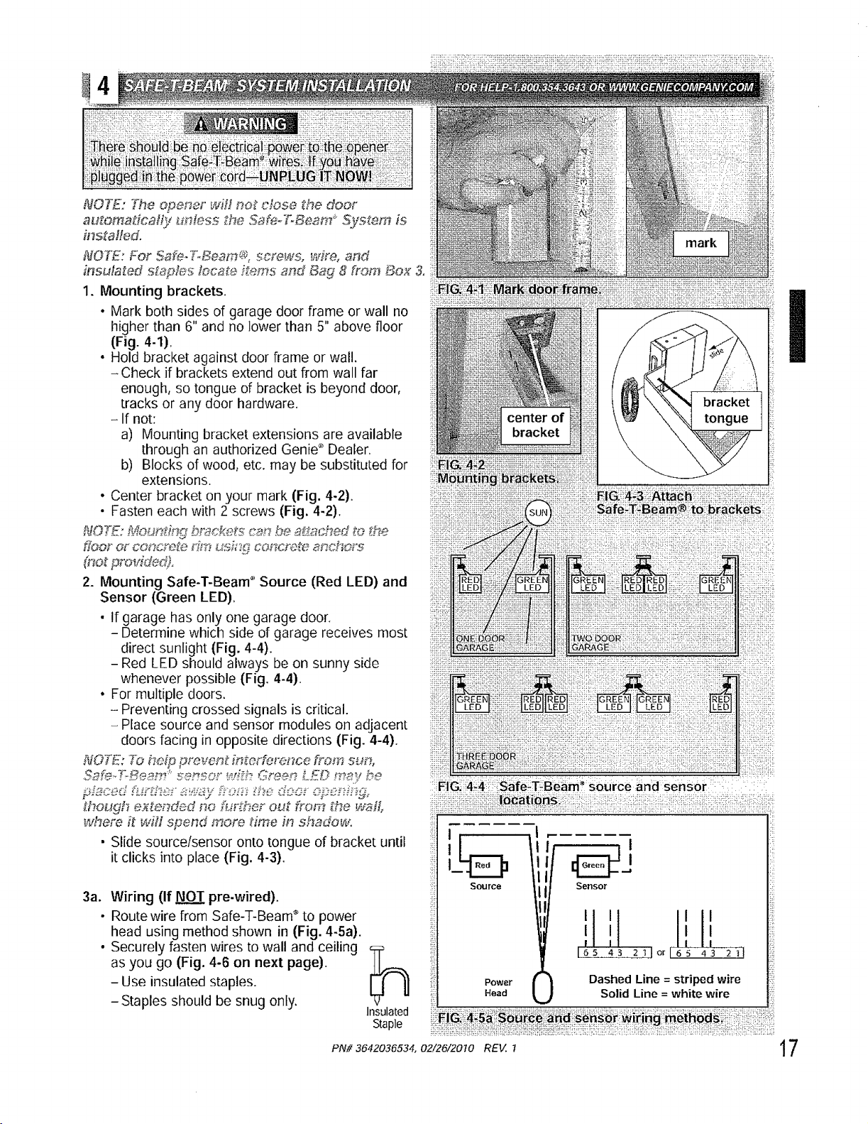
1, Mounting brackets.
• Mark both sides of garage door frame or wall no
higher than 6" and no lower than 5" above floor
(Fig. 4-1),
• Hold bracket against door frame or wall.
- Check if brackets extend out from wall far
enough, so tongue of bracket is beyond door,
tracks or any door hardware.
-If not:
a) Mounting bracket extensions are available
through an authorized Genie _ Dealer.
b) Blocks of wood, etc. may be substituted for
extensions.
• Center bracket on your mark (Fig. 4-2).
• Fasten each with 2 screws (Fig. 4-2).
NOTE: M,oun_ing bmcket_ _._,,'_'_b_,_a_ached to _._he.
fioo_ o_concrete _":_t_us,_:_gconcrd_ _nch_'_
_ot pro_e,d).
2. Mounting Safe-T-Beam _'Source (Red LED) and
Sensor (Green LED),
• If garage has only one garage door.
- Determine which side of garage receives most
direct sunlight (Fig. 4-4).
- Red LED should always be on sunny side
whenever possible (Fig. 4-4).
, For multiple doors.
- Preventing crossed signals is critical.
- Place source and sensor modules on adjacent
doors facing in opposite directions (Fig. 4-4).
N077i; ?_ he_p _rever# fni°e_'f_rence from su_,
_hough extended no further out from _'he waft
where f_ will spend morn time in shadow.
• Slide sourcelsensor onto tongue of bracket until
it clicks into place (Fig. 4-3).
3a. Wiring (If NOT pre-wired).
• Route wire from Safe-T-Beam" to power
head using method shown in (Fig. 4-5a).
• Securely fasten wires to wall and ceiling 5:P
as you go (Fig. 4-6 on next page).
-Use insulated staples.
-Staples should be snug only,
Insulated
Staple
i!ii ii !! i!i! iiiiiiiiiiiiiii!iii iiiii!i!iii!!iiiiiiiiiiiii!iiiii!i!ii!iiii!iii!iiii iiiiii
:_!i;iil;:iiiiii_}iiiiii}iiili!i;i_i_;i_!ii;iii!iii,iiii_ii_,iiii_i_i!i}ili i} i,:! ili:,:,!i;_!
::'.::!i:[_i!i[i!-_if_[i[i_fil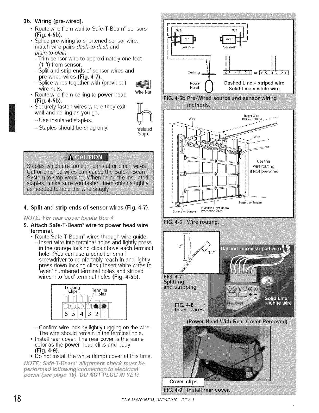
I
3b.
®
®
®
Wiring (pre-wired).
Route wire from wall to Safe-T-Beam _sensors
(Fig. 4-5b).
Splice pre-wiring to shortened sensor wire,
match wire pairs dash-to-dash and
plain-to-plain.
- Trim sensor wire to approximately one foot
(1 ft) from sensor.
- Split and strip ends of sensor wires and
pre-wired wires (Fig. 4-7).
- Splice wires together with (provided)
wire nuts.
Route wire from ceiling to power head Wire Nut
(Fig. 4-5b).
Securely fasten wires where they exit
wall and ceiling as you go.
-Use insulated staples.
-Staples should be snug only.
Insulated
Staple
4. Split and strip ends of sensor wires (Fig. 4-7).
5. Attach Safe-T-Beam ®wire to power head wire
terminal.
• Route Safe-T-Beam _ wires through wire guide.
-Insert wire into terminal holes and lightly press
in the orange locking clips above each terminal
hole. (You can use a pencil or small
screwdriver to comfortably reach in and lightly
press down locking clips.) Insert white wires to
'even' numbered terminal holes and striped
wires into 'odd' terminal holes (Fig. 4-5b).
Locking
i,l_s x_ Terminal
F_/Holes
/ F%q F%q
- Confirm wire lock by lightly tugging on the wire.
The wire should remain in the terminal hole,
• Install rear cover, The rear cover is the same
color as the power head clips and body
(Fig. 4-9).
, Do not install the white (lamp) cover at this time.
Power (
Head
'1 '1
I I
i6S 43 21]or165 43 211
)
Dashed Line = striped wire
Solid Line = white wire
Insert Wire
Wire Into Connector .... "'"
__ Wires
i IlJ_: _=_ _ _ [=_' ' i[ wirer°utinged
Source or Sensor
Source or Sensor ro ec ion rea
Cover clips
8 PNi/ 3642036534, 02/26/2010 REV. 1
i[ Motor Cover Screws
ii!ii!}iiiiii!¸}iiiii!i!iiiii!iiiiiii ili!i! iii!il¸ ii i ii! il¸i
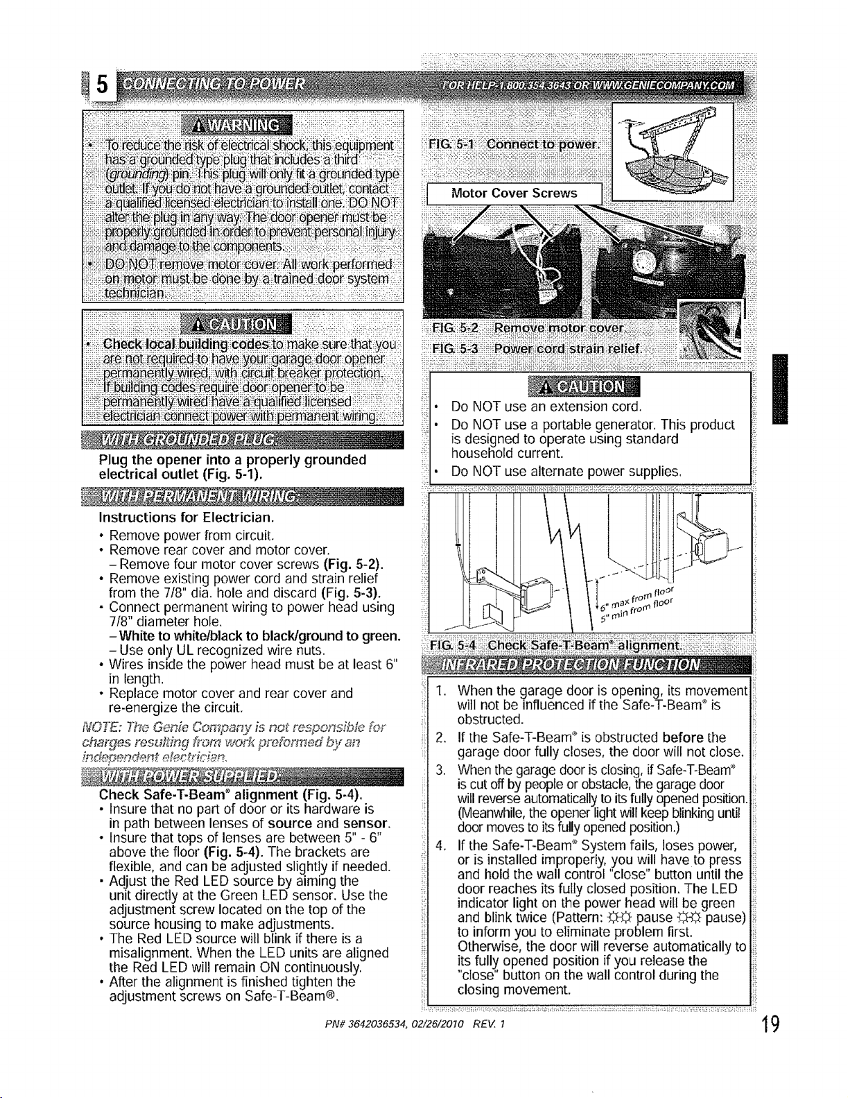
Plug the opener into a properly grounded
electrical outlet (Fig. 5-1).
Instructions for Electrician.
• Remove power from circuit.
° Remove rear cover and motor cover.
- Remove four motor cover screws (Fig. 5-2}.
• Remove existing power cord and strain relief
from the 7t8" dia. hole and discard (Fig. 5-3).
- Connect permanent wiring to power head using
7/8" diameter hole.
- White to white/black to black!ground to green.
- Use only UL recognized wire nuts.
• Wires inside the power head must be at least 6"
in length.
• Replace motor cover and rear cover and
re-energize the circuit.
_OZ_: The Gen_ C_paRy is no_ responJ.b_ _%_
/r__t et'_ctricf_zr_,
Check Safe-T-Beam" alignment (Fig. 5-4).
• Insure that no part of door or its hardware is
in path between lenses of source and sensor.
• Insure that tops of lenses are between 5" - 6"
above the floor (Fig. 5-4). The brackets are
flexible, and can be adjusted slightly if needed.
• Adjust the Red LED source by aiming the
unit directly at the Green LED sensor. Use the
adjustment screw located on the top of the
source housing to make adjustments.
• The Red LED source will blink if there is a
misalignment. When the LED units are aligned
the Red LED will remain ON continuously.
• After the alignment is finished tighten the
adjustment screws on Safe-T-Beam®.
i!! Ii!
• Do NOT use an extension cord. I
• Do NOT use a portable generator. This product
is designed to operate using standard
household current.
• Do NOT use alternate power supplies,
1. When the garage door is opening, its movement
will not be influenced if the Safe-T-Beam" is
obstructed.
2. If the Safe-T-Beam _ is obstructed before the
garage door fully closes, the door will not close.
3. When the garage door is closing, if Safe-T-Beam''
is cut off by people or obstacle, the garage door
will reverse automatically to its fully opened position.
(Meanwhile, the opener light will keep blinking until
door moves to its fully opened position.)
4. If the Safe-%Beam _ System fails, loses power,
or is installed improperly, you will have to press
and hold the wall control "close" button until the
door reaches its fully closed position. The LED
indicator light on the power head will be green
and blink twice (Pattern: _ pause -_ pause)
to inform you to eliminate problem first.
Otherwise, the door will reverse automatically to
its full_ opened position if you release the
"close' button on the wall control during the
closing movement.
PN#3642036534, 02/26/2010 REV. I 19
I
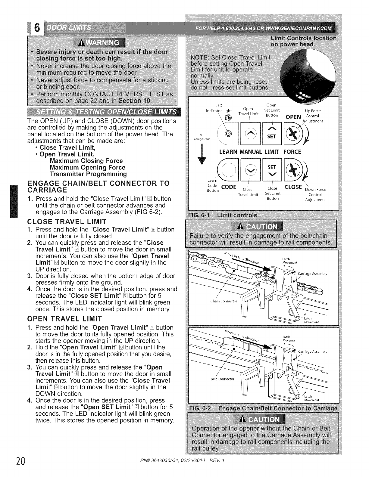
The OPEN (UP) and CLOSE (DOWN) door positions
are controlled by making the adjustments on the
panel located on the bottom of the power head. The
adjustments that can be made are:
• Close Travel Limit,
• Open Travel Limit,
Maximum Closing Force
Maximum Opening Force
Transmitter Programming
ENGAGE CHAIN/BELT CONNECTOR TO
CARRIAGE
1. Press and hold the "Close Travel Limit" D button
until the chain or belt connector advances and
engages to the Carriage Assembly (FIG 6-2).
CLOSE TRAVEL LIMIT
1. Press and hold the "Close Travel Limit" D button
until the door is fully closed.
2. You can quickly press and release the "Close
Travel Limit" [] button to move the door in small
increments. You can also use the "Open Travel
Limit"[] button to move the door slightly in the
UP direction.
3. Door is fully closed when the bottom edge of door
presses firmly onto the ground.
4. Once the door is in the desired position, press and
release the "Close SET Limit" [] button for 5
seconds. The LED indicator light will blink green
once. This stores the closed position in memory.
OPEN TRAVEL LIMIT
1. Press and hold the "Open Travel Limit" [] button
to move the door to its fully opened position. This
starts the opener moving in the UP direction.
2. Hold the "Open Travel Limit" [] button until the
door is in the fully opened position that you desire,
then release this button.
3. You can quickly press and release the "Open
Travel Limit"[] button to move the door in small
increments. You can also use the "Close Travel
Limit" [] button to move the door slightly in the
DOWN direction.
4. Once the door is in the desired position, press
and release the "Open SET Limit" [] button for 5
seconds. The LED indicator light will blink green
twice. This stores the opened position in memory.
To
Garage Door
LED
Indicator Light
Open
Open Bet Limit Up Force
\ ..... Travel Limit Button OPEN Control
//_ I /!_(1'_x 2 [ _L_/_)_ustment
i A,
',\ "-_' '\ / SET
....I II
LEARN MANUAL LIMIT FORCE
\
Code CODE Close CLOSE Down Force
Button Close
Travel Limit Set Limit Control
Button Adjustment
Latch
Movement
Carriage Assembly
Latch
Movement
Carriage Assembly
Belt Connector
Latch
Movement
0 PN# 3642036534, 02/26/2010 REV, 1
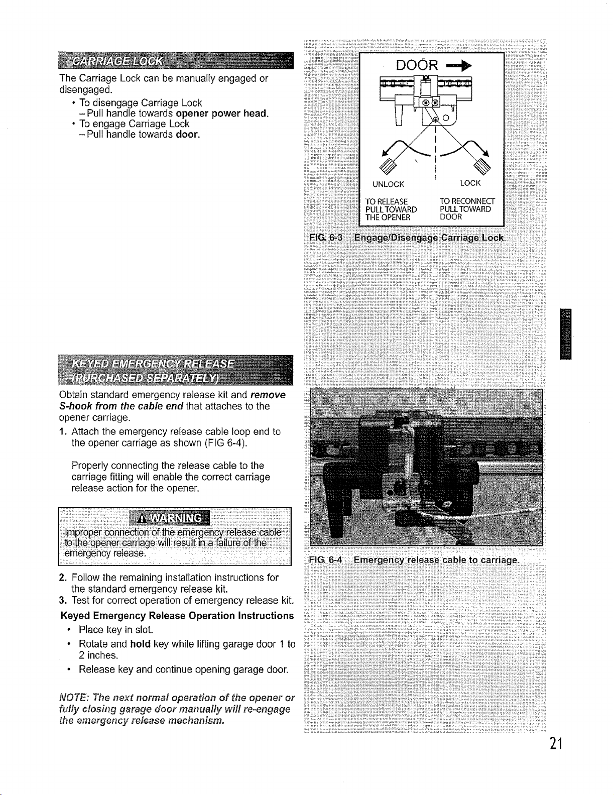
The Carriage Lock can be manually engaged or
disengaged.
• To disengage Carriage Lock
-Pull handle towards opener power head.
• To engage Carriage Lock
- Pull handle towards door.
Obtain standard emergency release kit and remove
S-hook from the cable end that attaches to the
opener carriage.
1. Attach the emergency release cable loop end to
the opener carriage as shown (FIG 6-4).
Properly connecting the release cable to the
carriage fitting will enable the correct carriage
release action for the opener.
f erfiergenby reteaseL :::_: :::::::::i:::
I
:::: : =: i:::J ..... i::,: ::ii :_:_i= ::: ::[: i:
I
2. Follow the remaining installation instructions for
the standard emergency release kit.
3. Test for correct operation of emergency release kit.
Keyed Emergency Release Operation Instructions
• Place key in slot.
• Rotate and hold key while lifting garage door 1 to
2 inches.
• Release key and continue opening garage door.
NOTE: The nex_ normal operation of _he opener or
fully closing garage door manually will re-engage
the emergency release mechanism.
:_ i_i_:!::"ii'._::": ::::i:':F::_!I '_: :!!: :::: ::_i :!_:f :!_ ::: :_ _::::::
21
1,
.
3.
,
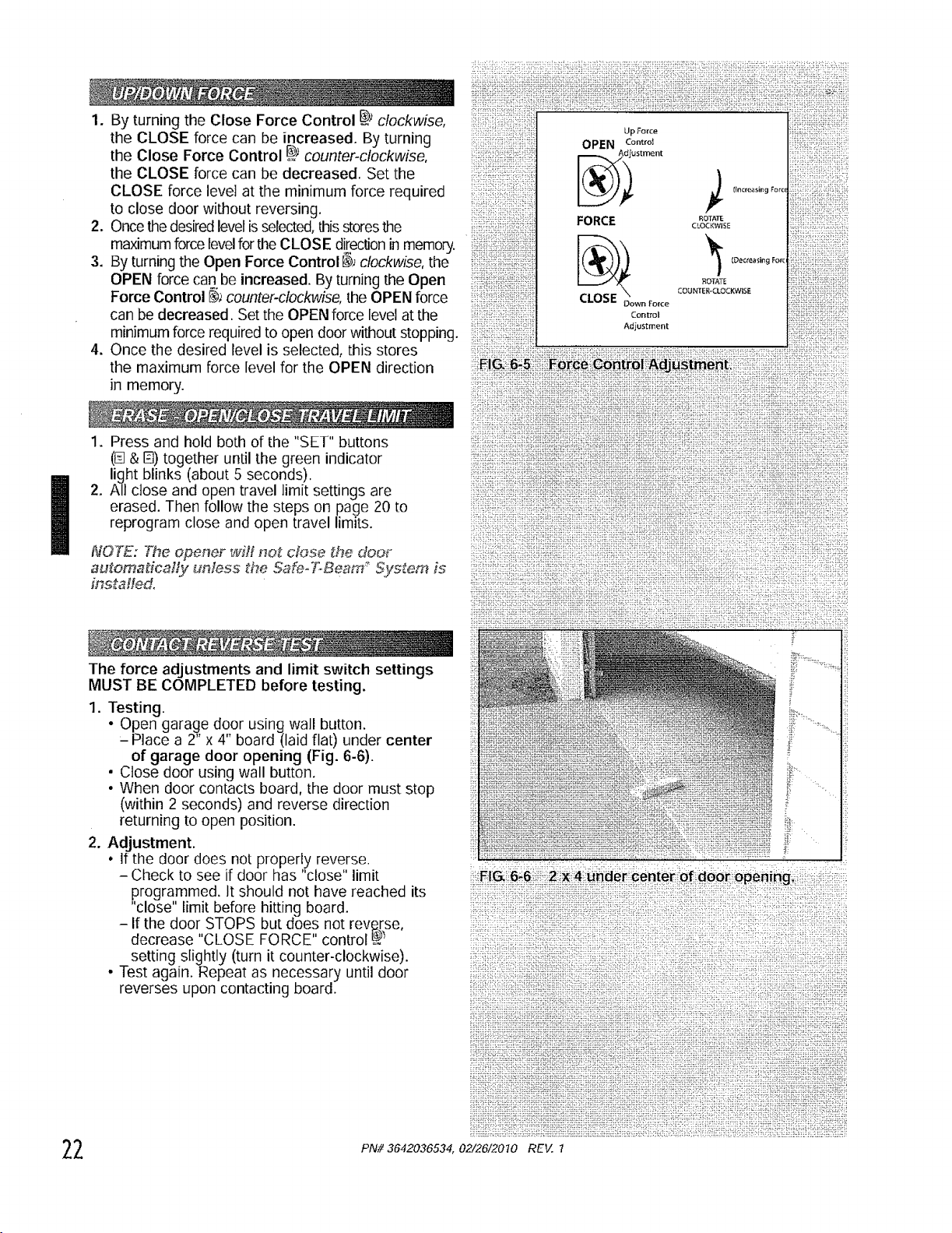
By turning the Close Force Control _; clockwise,
the CLOSE force can be increased. By turning
the Close Force Control _; counter-clockwise,
the CLOSE force can be decreased. Set the
CLOSE force level at the minimum force required
to close door without reversing.
Once the desiredlevel is selected,this storesthe
maximumforce levelfor the CLOSE directionin memory. !iliiiii::iiiii!ii;:ii!iill
By turning the Open Force Control _4 clockwise, the i!:i!:ili:_:ii::iiii;i:!iiii::i_:
OPEN force can be increased. By turning the Open :iiiii::ii!ii:iiiii!i!i!iiii:iii;il
Force Control _J counter-clockwise, the OPEN force
can be decreased. Set the OPEN force level at the ............................
minimum force required to open door without stopping.
Once the desired level is selected, this stores
the maximum force level for the OPEN direction
in memory.
1. Press and hold both of the "SET" buttons
(@& I_) together until the green indicator
light blinks (about 5 seconds).
2. All close and open travel limit settings are
erased. Then follow the steps on page 20 to
reprogram close and open travel limits.
NOT&-: The opener w_J_not c_ose _he doer
automatically unless _he Safe-T.Beam _"System is
installed.
The force adjustments and limit switch settings
MUST BE COMPLETED before testing.
1. Testing.
• Open garage door using wall button.
- Place a 2" x 4" board (laid flat) under center
of garage door opening (Fig. 6-6).
• Close door using wall button.
• When door contacts board, the door must stop
(within 2 seconds) and reverse direction
returning to open position.
2. Adjustment.
• If the door does not properly reverse.
- Check to see if door has "close" limit
programmed. It should not have reached its
"close" limit before hitting board.
- If the door STOPS but does not reverse,
decrease "CLOSE FORCE" control _
setting slightly (turn it counter-clockwise).
• Test again. Repeat as necessary until door
reverses upon contacting board.
2 PN# 3642036534, 02/26/2070 REV. 1
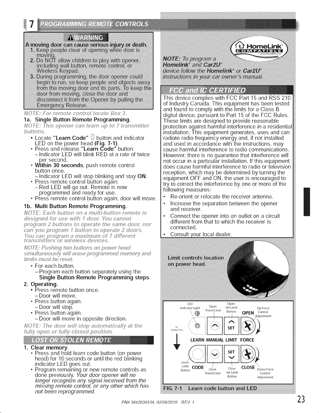
la. Single Button Remote Programming.
• Locate "Learn Code" _; button and indicator
LED on the power head (Fig. 7-1!.
• Press and release Learn Code button.
-indicator LED will blink RED at a rate of twice
..per second.
• Within 30 seconds, push remote control
button once.
-indicator LED will stop blinking and stay ON.
• Press remote control button again.
- Red LED will go out. Remote is now
programmed and ready for use.
• Press remote control button again, door will move.
lb. Multi Button Remote Programming.
@s_#ned fO__ use wf#_ doos tbs c_nno_
TE: hmxj t'_'a_bu s o_'_pow_.fr he,_d
• For each button.
- Program each button separately using the
Single Button Remote Programming steps.
2. Operating.
• Press remote button once.
- Door will move.
• Press button again.
- Door will stop.
• Press button again.
- Door will move in opposite direction.
_0 T_E: _:_e d,:_o'_v_,'H:i_o7::_.,_ _::_;_,_c:_ f_;_,_ #_e
f_._@open or f_.#!y ck;_sed posR:<_n
1. Clear memory.
• Press and hold learn code button (on power
head) for 10 seconds or until the red blinking
indicator LED goes out.
• Program remaining or new remote controls as
done previous!y. Your door opener will no
longer recogmze any signal received from the
missing remote control, or any other which has
not been reprogrammed.
This device complies with FCC Part 15 and RSS 210
of Industry Canada. This equipment has been tested
and found to comply with the limits for a Class B
digital device, pursuant to Part 15 of the FCC Rules.
These limits are designed to provide reasonable
protection against harmful interference in a residential
installation. This equipment generates, uses and can
radiate radio frequency energy and, if not installed
and used in accordance with the instructions, may
cause harmful interference to radio communications.
However, there is no guarantee that interference will
not occur in a particular installation. If this equipment
does cause harmful interference to radio or television
reception, which may be determined by turning the
equipment OFF and ON, the user is encouraged to
try to correct the interference by one or more of the
following measures:
, Re-orient or relocate the receiver antenna.
, Increase the separation between the opener
and receiver.
, Connect the opener into an outlet on a circuit
different from that to which the receiver is
connected.
Consult _our local dealer.
LED Open
Indicator Light Open Set Limit
,\ Travel Limit Button
\
To
Garage Door
Up Force
OPEN Control
ustment
LEARN MANUAL LIMIT FORCE
' i
BCt_oen CODE Close Close C_OSE D_ownF ....
Travel Limit Bet Limit Control
Button Adjustment
I
PN#3642036534,02/26/2010 REV. 1 23
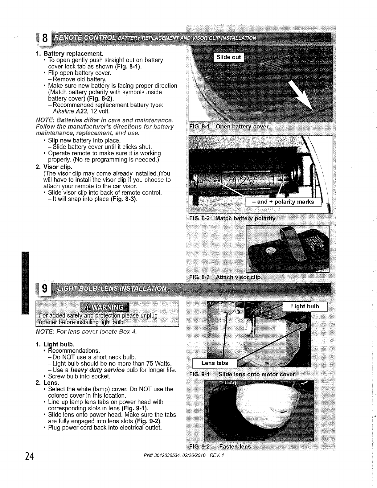
1. Battery replacement,
• To open gently push straight out on battery
cover lock tab as shown (Fig. 8-1).
• Flip open battery cover.
-Remove old battery.
° Make sure new battery is facing proper direction
(Match battery polarity with symbols inside
battery cover) (Fig. 8-2).
- Recommended replacement battery type:
Alkaline A23, 12 volt.
NOTE," Batteries differ in care and maintenance.
Follow the manufacturer's direc_,ons for battery
maintenance, replacement, and use.
• Slip new battery into place.
-Slide battery cover until it clicks shut.
• Operate remote to make sure it is working
properly. (No re-programming is needed.)
2. Visor clip.
(The visor clip may come already installed.)You
will have to install the visor clip if you choose to
attach your remote to the car visor.
• Slide visor clip into back of remote control.
-It will snap into place (Fig. 8-3).
,_ii_i_ii:¸_:i::_:_ii_iiiii_iiiii_i_ii_i_iii_i_i_ii_iii_i!ii_iiiii!ii_i!_iii_iii_ii!_!i_iii_iiiii_!i_i!i_ii_!i_!_!!_!_!_!_i_!i_!_
Light bulb
1. Light bulb.
• Recommendations.
- Do NOT use a short neck bulb.
- Light bulb should be no more than 75 Watts.
- Use a heavy duty service bulb for longer life.
• Screw bulb into socket.
2. Lens.
• Select the white (lamp) cover. Do NOT use the
colored cover in this location.
• Line up lamp lens tabs on power head with
corresponding slots in lens (Fig. 9-1).
• Slide lens onto power head. Make sure the tabs
are fully engaged into lens slots (Fig. 9-2).
• Plug power cord back into electrical outlet.
il Lo.stabs
24
:_i_
PN# 3642036534,02/26/20t0 REV, I
.
2.
3.
.
5.
.
.
.
.
0 uce i'ls
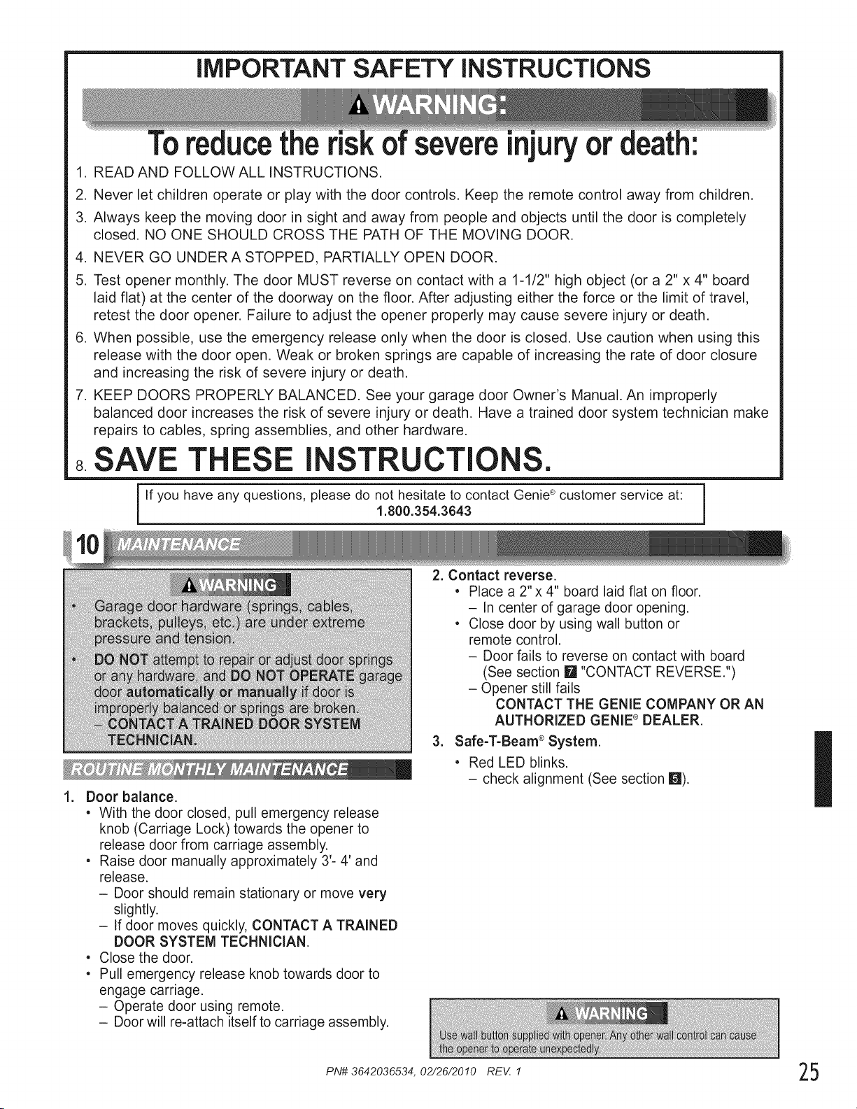
READ AND FOLLOW ALL INSTRUCTIONS.
severeinjury or
Never let children operate or play with the door controls. Keep the remote control away from children.
Always keep the moving door in sight and away from people and objects until the door is completely
closed. NO ONE SHOULD CROSS THE PATH OF THE MOVING DOOR.
NEVER GO UNDER A STOPPED, PARTIALLY OPEN DOOR.
Test opener monthly. The door MUST reverse on contact with a 1-1/2" high object (or a 2" x 4" board
laid flat) at the center of the doorway on the floor. After adjusting either the force or the limit of travel,
retest the door opener. Failure to adjust the opener properly may cause severe injury or death.
When possible, use the emergency release only when the door is closed. Use caution when using this
release with the door open. Weak or broken springs are capable of increasing the rate of door closure
and increasing the risk of severe injury or death.
KEEP DOORS PROPERLY BALANCED. See your garage door Owner's Manual. An improperly
balanced door increases the risk of severe injury or death. Have a trained door system technician make
repairs to cables, spring assemblies, and other hardware.
SAVE T ESE I STRUCTI .
3
If you have any questions, please do not hesitate to contact Genie ®customer service at:
1.800.354.3643
1
Door balance.
• With the door closed, pull emergency release
knob (Carriage Lock) towards the opener to
release door from carriage assembly.
• Raise door manually approximately 3'- 4' and
release.
- Door should remain stationary or move very
slightly.
- If door moves quickly, CONTACT A TRAINED
DOOR SYSTEM TECHNICIAN,
• Close the door.
• Pull emergency release knob towards door to
engage carriage.
- Operate door using remote.
- Door will re-attach itself to carriage assembly.
2. Contact reverse.
• Place a 2"x 4" board laid flat on floor.
- In center of garage door opening.
• Close door by using wall button or
remote control.
- Door fails to reverse on contact with board
(See section li_ "CONTACT REVERSE.")
- Opener still fails
CONTACT THE GENIE COMPANY OR AN
AUTHORIZED GENIE ® DEALER.
3. Safe-T-Beam ®System.
• Red LED blinks.
- check alignment (See section i_!).
I
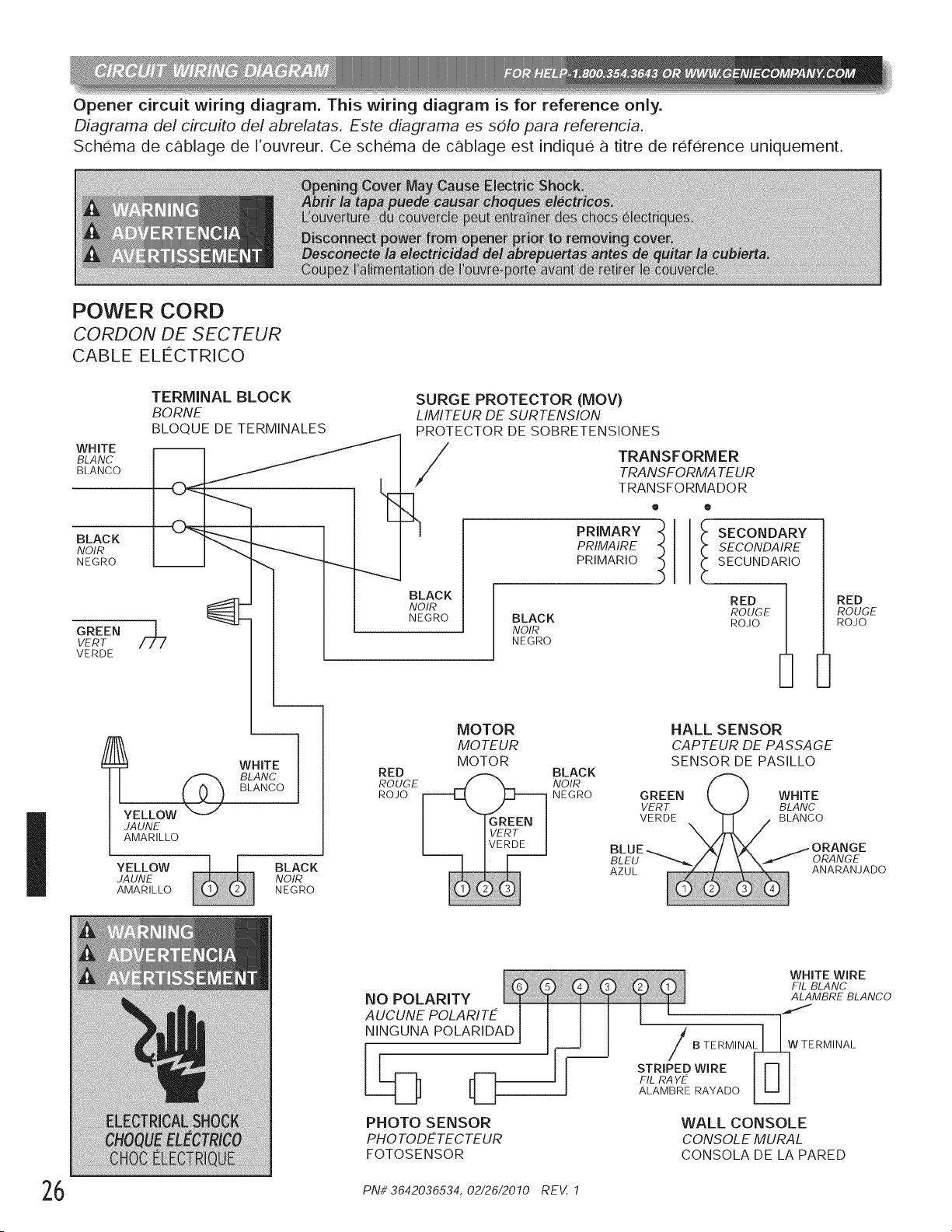
Opener circuit wiring diagram. This wiring diagram is for reference only.
Diagrama del circuito del abrelatas. Este diagrama es solo para referencia.
Schema de cSblage de I'ouvreur. Ce schema de cSblage est indique a titre de rderence uniquement.
POWER CORD
CORDON DE SECTEUR
CABLE ELECTRICO
I
WHITE
BLANC
BLANCO
TERMINAL BLOCK
BORNE
BLOQUE DE TERMINALES
-- /
BLACK
NOIR
717 NEGRO
SURGE PROTECTOR (MOV)
LIMITEUR DE SURTENSION
PROTECTOR DE SOBRETENSIONES
TRANSFORMER
TRA NSFORMA TEUR
TRANSFORMADOR
o •
BLACK
NOIR
NEGRO
GREEN
VERT
VERDE
I o%
YELLOW _-_/
JA UNE
AMARILLO
WHITE
BLANC
BLANCO
RED
ROUGE
ROJO
PRIMARY
PRIMAIRE
PRIMARIO
BLACK
NOIR
NEGRO
MOTOR
MO TEUR
MOTOR
BLACK
NOIR
NEGRO
I ECONDARY
SECONDA IRE
SECUNDARIO
RED _
ROUGE
ROJO
HALL SENSOR
CAPTEUR DE PASSAGE
SENSOR DE PASILLO
YELLOW
JA UNE
AMARILLO
BLACK
NOIR
NEGRO
RED
ROUGE
ROJO
NO POLARITY
AUCUNE POLARIT£
NINGUNA POLARIDAD
PHOTO SENSOR
PHOTODETECTEUR
FOTOSENSOR
WHITE WIRE
FIL BLANC
ALAMBRE BLANCO
B TERMINAL_WTERMINAL
STRIPEDWIRE lull
FIL RAYE II II
ALAMBRE RAYADO _
WALL CONSOLE
CONSOLE MURAL
CONSOLA DE LA PARED
6 PNi/ 3642036534, 02/26/2010 REV. 1
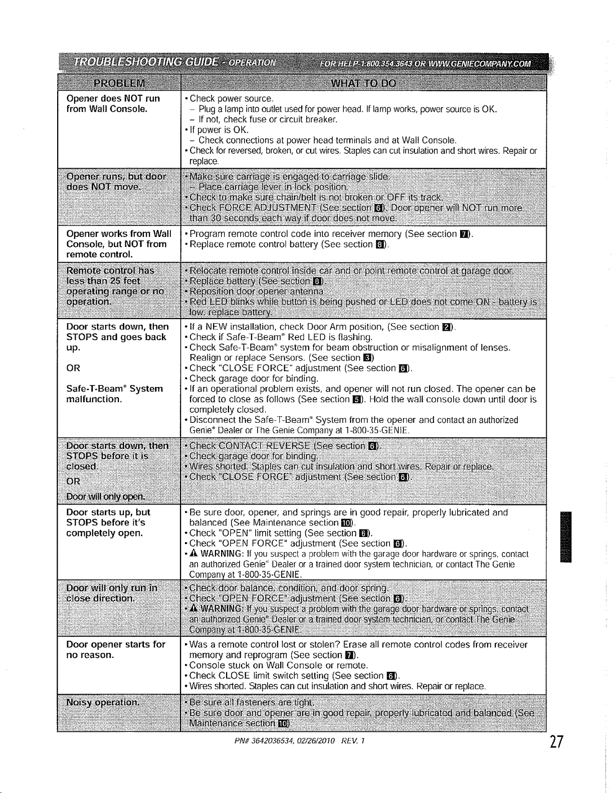
Opener does NOT run
from Wall Console.
• Check power source.
- Plug a lamp into outlet used for power head. If lamp works, power source is OK.
- If not, check fuse or circuit breaker.
• If power is OK.
- Check connections at power head terminals and at Walt Console.
• Check for reversed, broken, or cut wires. Staples can cut insulation and short wires. Repair or
replace.
• Program remote control code into receiver memory (See section El).
• Replace remote control battery (See section _1).
OR
Safe-T-Beam* System
malfunction.
•If a NEW installation, check Door Arm position, (See section I_).
• Check if Safe4-Beam ° Red LED is lashing.
• Check Safe-T-Beam _'system for beam obstruction or misalignment of lenses.
Realign or replace Sensors. (See section M)
• Check "CLOSE FORCE" adjustment (See section El).
• Check garage door for binding.
• If an operational problem exists, and opener will not run closed. The opener can be
forced to close as follows (See section !fl). Hold the wall console down until door is
completely closed,
• Disconnect the Safe-T-Beam ;°System from the opener and contact an authorized
Genie®Dealer or The Genie Company at 1-800-35-GENIE.
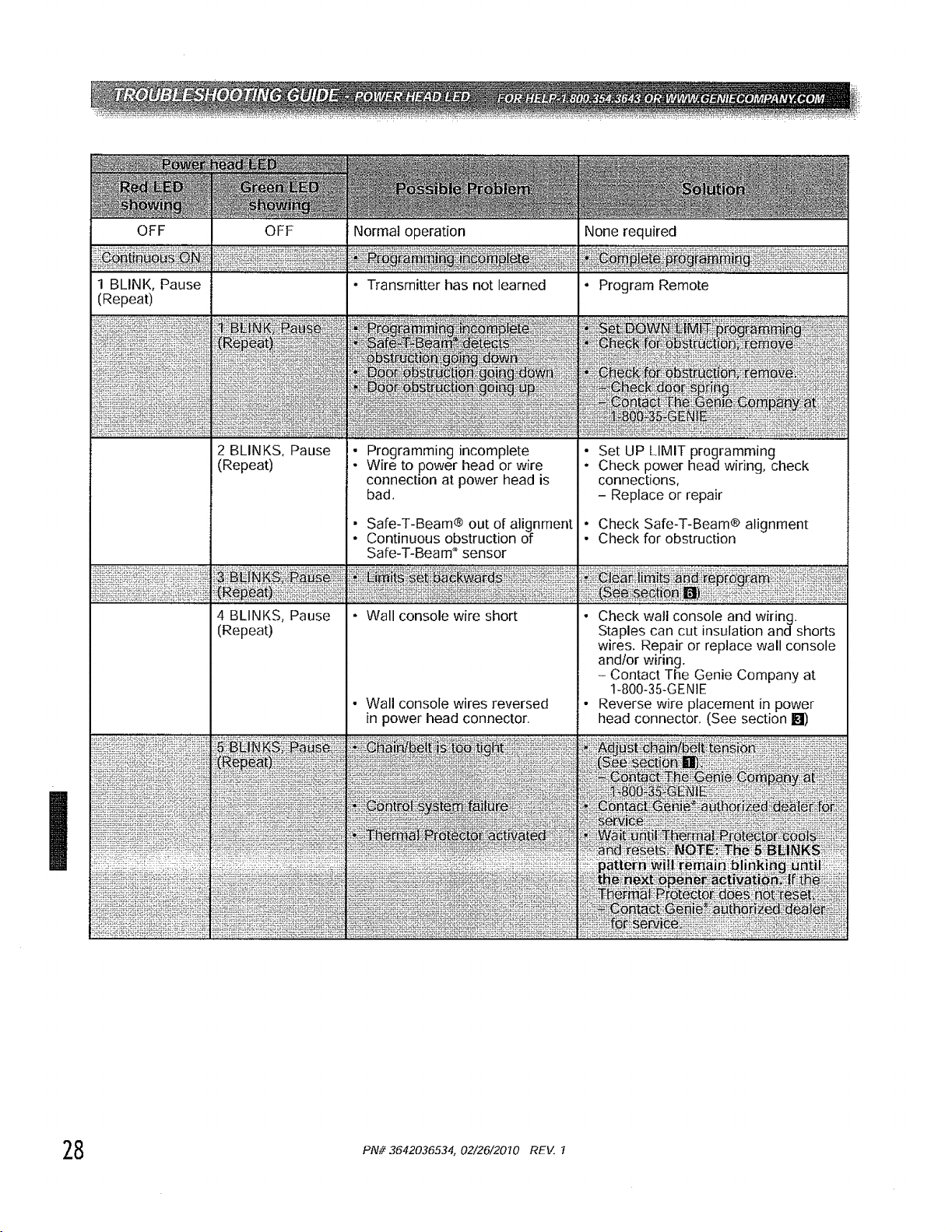
OFF OFF
1 BLINK, Pause
(Repeat)
2 BLINKS, Pause
(Repeat)
4 BLINKS, Pause
(Repeat)
Normal operation
• Transmitter has not learned
• Programming incomplete
Wire to power head or wire
connection at power head is
bad,
• Safe-T-Beam® out of alignment
• Continuous obstruction of
Safe-T-Beam" sensor
• Wall console wire short
• Wall console wires reversed
in power head connector.
None required
• Program Remote
Set UP LIMIT programming
Check power head wiring, check
connections,
- Replace or repair
• Check Safe-T-Beam® alignment
• Check for obstruction
• Check wall console and wiring.
Staples can cut insulation and shorts
wires. Repair or replace wall console
andlor wiring.
- Contact The Genie Company at
1-800-35-GENIE
• Reverse wire placement in power
head connector. (See section _1)
8 PAl# 3642036534, 02/26/2010 REV. I
TRANSMITTER COMPLIANCE STATEMENT
Transmitters comply with all United States and Canadian legal requirements as of the date of manufacture. No warranty is made
that they comply with all legal requirements of any other jurisdiction. If transmitters are to be used in another country, the importer
must determine compliance with any local laws and regulations which may differ from United States and Canadian requirements
prior to use.
Los transmisores cumplen con todas las reglamentaciones legales de los Estados Unidos y del Canada, en la fecha de fabricaci6n.
Ninguna garantia se da que cumplan con todas las reglamentaciones legales de ninguna otra jurisdicci6n. Si los transmisores se
van a utilizar en otro pais, el importador debe determinar si cumplen con las reglamentaciones y byes locales que puedan ser
diferentes alas reglamentaciones de los Estados Unidos y del Canada, antes de usar los mismos.
Les emetteurs sont conformes _ la reglementation am@icaine et canadienne _ compter de leur date de fabrication. Aucune garantie
n'est stipulee indiquant qu'ils sont conformes a toutes les prescriptions juridiques d'autres autorites. Si les emetteurs sont utilises
dans d'autres pays, il incombe _ I'importateur d'en determiner leur conformite aux lois et regles locales pouvant differer de celles
des Etats Unis et du Canada avant toute utilisation desdits emetteurs.
Sendeger_te entsprechen allen gesetzlichen Bestimmungen in den USA und Kanada zum Zeitpunkt der Herstellung. Wir
0bernehmen keine Gew_hrleistung for die Einhaltung aller gesetzlichen Bestimmungen in anderen L_ndern. Sollen Sendeger_te in
anderen L_ndern eingesetzt werden, so muss der Importeur vor dem Gebrauch sicherstellen, dass die Sendegergte auch solchen
Iokalen Bestimmungen entsprechen, welche von den Bestimmungen der USA und Kanadas abweichen.
k::t_
PN# 3642036534, 02/26/2010 REV. 1 29

MODELS 1022/1024/1042
LIMITED WARRANTY
GMI Holdings, Inc d&ia The Genie Company ("Seller") warrants to the original purchaser of the below identified opener Model 1022 or opener Model 1024 or
opener Model 1042 ("Product"), subject to all of the terms and conditions hereof, that the Product and all components thereof will be free from detects in
materials and workmanship tbr the tbllowing period(s) of time, measured from the date ofpnrchase:
MOTOR - Seller warrants the motor tbr a period of FIVE (5) YEARS
PARTS - Seiier warrants all other parts and components tbr a period of ONE (1) YEAR
Seller's obligation nnder this warranty is specifically limited to repairing or replacing, at its option, the Product or any part thereof which is determined by
Seller to be defective during the applicable warranty period Any labor charges are excluded and will be the responsibility of the pnrchaser
This warranty gives you specific legal rights, and you may also have other rights which valT fi_omstate to state This warranty is made to the original
pnrchaser of the Product only, and is not transferable or assignable This warranty applies only to Product installed in a residential or other non-commercial
application It does not cover any Product installed in commercial or industrial building applications This warranty does not apply to any unauthorized or
improper installation, alteration or repair of the Product, or to anv Product or component which has been damaged or deteriorated due to misuse, neglect,
accident, fi_ilure to provide necessal T maintenance, normal wear and tear, or acts of God or any other cause bevond the reasonable control of Seller, and does
not cover batteries, missing or damaged parts t?om clearance or open box sales, or repairs or maintenance to door components
ALL EXPRESS AND IMPLIED WARRANTIES FOR THE PRODUCT, INCLUDING BUT NOT LIMITED TO ANY IMPLIED WARRANTIES OF
MERCHANTABILITY AND FITNESS FOR A PARTICULAR PURPOSE, ARE LIMITED IN TIME TO THE APPLICABLE WARRANTY PERIOD
REFLECTED ABOVE NO WARRANTIES, WHETHER EXPRESS OR IMPLIED, WILL APPLY AFTER THE LIMITED WARRANTY PERIOD HAS
EXPIRED Sonre states do not allow limitations on how long an implied warranty lasts, so the above limitation nray not apply to you
IN NO EVENT SHALL GMI HOLDINGS, IN(: OR OVERHEAD DOOR CORPORATION BE RESPONSIBLE FOR, OR LIABLE TO ANYONE FOR,
SPECIAL, INDIRECT, COLLATERAL, PUNITIVE, INCIDENTAL OR CONSEQUENTIAL DAMAGES, even if Seller has been advised of the possibility
of such damages Such excluded damages include, but are not limited to, loss of use, cost of any substitnte product, or other similar indirect financial loss
Sonre states do not allow the exclusion or limitation of incidental or consequential damages, so the above limitation or exclusion nray not apply to you
Claims under this warranty must be made promptiy after discovery and within the applicable warranty period To obtain warranty service, you must contact
Geniea? customer service and provide proof of the date and location of purchase and identification as the original purchaser (?all Geniea? Customer Service toll
fi_ee at 1-800-354-3643 to speak with a trained representative Purchaser must allow seller a reasonable opportunity to inspect Product claimed to be defective
prior to removal or alteration of its condition Upon determination by Seller that the Product or any part thereof is detective during the applicable warranty
period (which may require purchaser to return the Product to Seller at purchaser's expense), Seller will supply the purchaser with replacement parts or, at its
option, a replacement Product Seller may use new or reconditioned parts, or a new or reconditioned Product of the same or similar design
There are no established infbrmal dispute resolntion procedures of the type described in the Magnuson-Moss Warranty Act
PURCHASER:
INSTALLATION ADDRESS:
DATE PURCHASED: SERIAL NUMBER:
OPENER MODEL:
REMOTE CONTROL MODEL:
DEALER NAME:
DEALER ADDRESS:
P900-775