
Technical Support and E-Warranty Certificate https://www.vevor.com/support
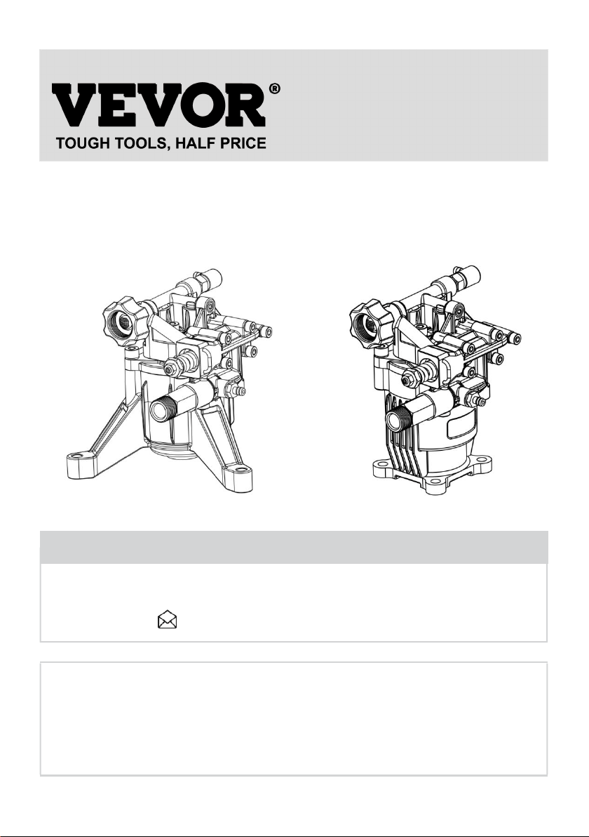
PRESSURE WASHER PUMP
USER MANUAL
MODEL: KXD1810G/KXA1810G
We continue to be committed to provide you tools with competitive price.
"Save Half", "Half Price" or any other similar expressions used by us only represents an
estimate of savings you might benefit from buying certain tools with us compared to the major
top brands and doses not necessarily mean to cover all categories of tools offered by us. You
are kindly reminded to verify carefully when you are placing an order with us if you are
actually saving half in comparison with the top major brands.

- 1 -
Have product questions? Need technical support? Please feel free to
contact us:
CustomerService@vevor.com
NEED HELP? CONTACT US!
This is the original instruction, please read all manual instructions
carefully before operating. VEVOR reserves a clear interpretation of our
user manual. The appearance of the product shall be subject to the
product you received. Please forgive us that we won't inform you again if
there are any technology or software updates on our product.
PRESSURE WASHER PUMP
KXD1810G
KXA1810G
- 2 -
GENERAL INEORMATLON
Purpose of the manual
The manufacturer has provided this manual to provide the operating
instructions and the criteria to be complied with when installing, using, and
maintaining the pump identified by the designation on the cover.
The manufacturer supplies the original instructions in the English
language.
The manufacturer may supply the original instructions in other languages
in response to statutory or commercial requirements.
If the pump is sold, the seller must pass on this manual to the new owner
along with the appliance.
The instructions are intended for the skilled, suitably trained operators who
carry out the installation and routine maintenance procedures.
Refer to the table of contents for rapid access to the topics covered.
The manufacturer reserves the right to amend the manual without notice
unless the amendments refer to the pump's level of safety.
The purchaser must ensure that the installation is designed in accordance
with the instructions in this manual, statutory requirements, and the
relevant national and local regulations.
The technical instructions in this "Use and Installation Manual" are the
property of the manufacturer and must be treated as confidential.
There may be differences between the illustrations and the pump's actual
conformation, but any such differences will not affect the clarity of the
instructions. If in doubt, request the necessary explanations from the
manufacturer.
The symbols shown and described below are used to identify safety
risks or important information.
Danger-Warning
Identifies information or procedures the failure to comply with, which may
constitute a serious threat to health and safety.
- 3 -
Caution
Identifies information or procedures the failure to comply with, which may
constitute a threat to health and safety or cause damage.
Information
Identifies useful and important information or procedures that should be
borne in mind.
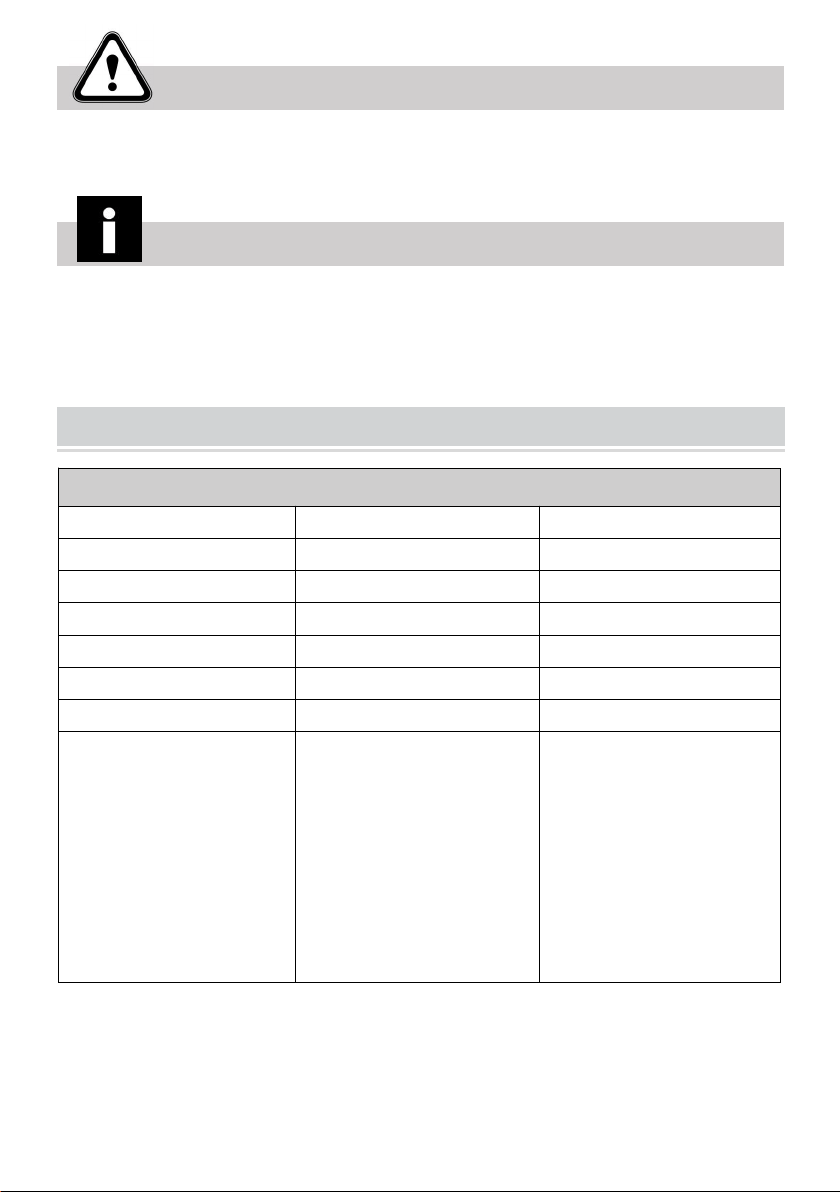
TECHNICAL INEORMATION
Product Specifications and Packing List
Model
KXD1810G
KXA1810G
Working Pressure
3100 PSI
3100 PSI
Gun Closing Pressure
3400 PSI
3400 PSI
Factory Set Pressure
2300-2400 PSI
2300-2400 PSI
Matching Horsepower
6.5-7/HP
6.5-7/HP
Maximum Flow
2.5 GPM
2.5 GPM
Adaptive Model
196-230CC
196-230CC
Packing List
1 x Pressure Washer
Pump;
1 x Siphon;
3 x Bolts;
1 x Shaft Key;
3 x Flat Pads;
3 x Spring Washers;
1 x Manual
1 x Pressure Washer
Pump;
1 x Siphon;
4 x Bolts;
1 x Shaft Key;
4 x Flat Pads;
4 x Spring Washers;
1 x Manual
- 4 -
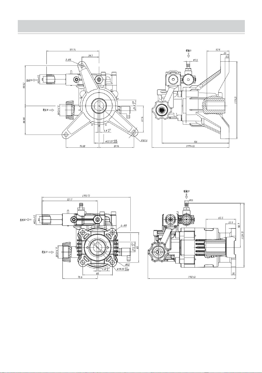
PRODUCT SIZE
(
Unit:mm
)
(Unit:mm)
KXD1810G
KXA1810G
- 5 -
Technical Data
The technical and performance data are stated on the cover.
The pump's intake circuit must include a filter having a capacity at least
twice the pump's delivery rate, which must not cause restrictions or head
losses. The recommended degree of filtration is 50-80 mesh. Maximum
intake vacuum-0.25 bar, measured at the pump intake.
Overall dimensions
The illustrations showing the overall dimensions are provided in the
annexes.
Environmental operating limits
The pump operates correctly at an ambient temperature between 10 and
40°C, with a relative humidity of 80%.
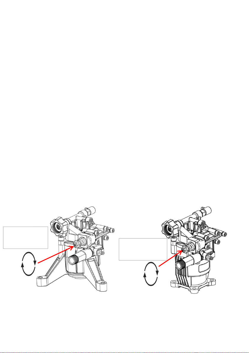
Note: To match engines with different power, the factory set pressure will be
less than the rated maximum pressure. Just adjust the pressure limiting
valve if you need to increase the pressure.
Note:
1. Turn clockwise to increase pressure.
2. Adjustment tools: 2.5 mm Allen wrench and 17 mm open-end wrench.
Turn clockwise to
increase pressure
Turn clockwise to
increase pressure
- 6 -
OPERATION NOTICE
1. Prepare
Before use, connect the matching outlet pipe, inlet pipe, water absorption
filter, etc., and check whether the fasteners and pipe joints are loose.
Connect the inlet and outlet pipes of the pump, and install a filter device of
no less than 40 mesh/inch at the inlet end to avoid debris entering the
pump and affecting the normal operation of the pump.
2. Adjust the pressure
The pump has been adjusted to the rated pressure, and you do not need to
adjust it again. If you need to adjust the low pressure, you should first turn
on the pressure washer gun and then use the special pressure regulating
tool to adjust the pressure regulating screw while spraying so that the
pressure reaches the predetermined value, and you can start to work.
Danger-Warning
Do not aim the spray gun at people, animals, and equipment!
3. Precautions for use
When working, it should be noted that the pressure of the pump should not
exceed the maximum pressure; otherwise, the pump pressure should be
lowered to avoid damage to the pump overload. The pump adopts an
internal backwater structure. When the water is shut down, the operation
time should not exceed 90S. If it exceeds 2 min, it is recommended to shut
down the equipment! It is normal to have drop oil or drop water during
operation but the leakage does not exceed 1 ml/min (or 10 drops/min).
4. Applicable occasion
This pump is suitable for high-pressure cleaning and all kinds of
commercial or civil needs high-pressure occasions.

- 7 -
5. Medium and temperature
The conveying medium of the KX series pump is clear water, and the
highest water inlet temperature shall not exceed 40℃. Too high inlet water
temperature will cause damage to the pump and affect the service life of
the pump. For the pump group that runs continuously for a long time, our
company suggests using the booster pump for inlet water. The rated flow of
the booster pump is at least twice the rated flow of the pump, and the
output of the booster pump should be about 2-3 bar. If the user delivers
other media other than clean water or the inlet water temperature is higher
than 40℃ in actual use, please contact our relevant personnel.
6. Maximum flow rate and maximum pressure
The flow and pressure values of the pump indicated in the technical
parameter table describe the maximum performance of the pump. The
maximum rotational speed and pressure values used shall not exceed their
set value.
7. Power selection
KX series pump is driven by a gasoline engine. When choosing the power,
the power value is higher than the set parameters to ensure the
performance of the pump.
Misuses
Do not put the pump into service until the plant or machinery in which it is
incorporated has been declared compliant with the relevant national and
local legal requirements.
Do not use the pump in a potentially explosive atmosphere.
Do not use the pump for flammable, toxic, or corrosive liquids or those with
unsuitable density. Do not take in liquids at temperatures higher than those
specified in the technical data.

- 8 -
Do not use the pump for the supply of drinking water.
Do not use the pump on products for human consumption.
Do not use the pump on pharmaceutical products.
Residual risks
Even if the safety regulations and information provided in the manual are
complied with, the residual risk described below is still present during the
use of the pump.
- Thermal hazard: Depending on the temperature of the liquid pumped,
the pump may reach high temperatures when in operation. The designer of
the installation must therefore bear this in mind and provide the appropriate
measures and warning signs for staff.
MAINTENANCE AND MAINTENANCE
1. Idle pumps and water pipes for long periods of time.
a. Run the pump with clean water for a few minutes.
b. After turning off the water source, run the pump for 10 seconds, and
empty the water in the pump and pipeline to prevent scale.
c. Blow-dry the pump with compressed air.
d. Take appropriate protective measures to avoid environmental impact.
e. Use the tap water to run for 2 min until the gun is out of water. If there
is no water, please stop to check.
* When choosing the gasoline engine as the power, check the oil quantity
of the gasoline engine before each start.
* When the pump performance is significantly reduced, it shall be
maintained immediately.
* Continuous working time, water temperature, and cleanliness of water
all affect the performance of the pump, so users can adjust the

- 9 -
maintenance time according to the actual use situation.
2. Inspection and repair
a. Often check whether the connection part is loose.
b. It is normal for the moving seal to drop oil or water during operation,
but the dripping amount does not exceed 1 ml/min (or 10 drops/min);
otherwise, the oil seal or water seal should be replaced.
SAFETY INEORMATION
General safety rules
Most workplace accidents and injuries are caused by carelessness and
failure to comply with common sense and safety rules.
In most cases, accidents can be avoided by predicting their possible
causes and proceeding with the necessary care and attention.
A careful operator who follows the rules is the best guarantee against
accidents.
Before installing and using the pump, the operators and other staff must
read and understand the instructions in the manual provided and the
details of the installation design.
Do not tamper with, disarm, or by-pass the safety devices, as this may
cause serious threats to health and safety. Do not release pollutants into
the environment.
Dispose of waste in accordance with statutory requirements.
Before performing any procedure, adopt appropriate safety measures in
accordance with the relevant statutory occupational safety requirements
and comply with the safety regulations in the manual.

- 10 -
INSTALLATLON INSTRUCTIONS
Safety recommendations for installation
Take all possible precautions to allow the pump to be installed in a safe,
risk-free manner.
All installation phases must be taken into consideration when designing the
machinery or plant in which the pump is to be installed.
The design must consider all mounting points, the means of transmission
of the energy sources, and the protective and safety devices required by
the relevant regulations to prevent the risk of injury.
General guidelines on water supply connection
The pump's water supply connection can be made in one of the ways listed
below.
Connection to the mains water supply.
Connection to a tank (gravity-feed).
Connection to an external pump (force-feed).
The following requirements must be met for all types of connection.
1) The pump must be supplied by means of a crush-proof hose of suitable
diameter for the pump's intake connection (see "Technical Data").
2) There must be no restrictions or kinks in the hose.
3) A suitable filter must be installed at the pump intake (see "Technical
Data").
4) All connections between the unions and the intake line must be sealed
to prevent the pump from sucking in the air.
5) The connections and pipes must be suitable for the operating pressure
and the pump delivery rate and must comply with the relevant
regulations.
6) To ensure operating safety install a relief valve (by-pass valve) suitable
for the pump's technical data and with a suitable setting downstream of
the pump.

- 11 -
7) The relief valve dump line must never be connected to the pump intake
line.
8) Install a pressure damper downstream of the pump to minimize the
water hammer effect in the delivery pipeline.
Connection to the mains water supply
The connection must comply with the recommendations provided.
The mains water system must have a flow rate twice the pump's rated
delivery rate and a pressure of 2-3 bar.
INSTRUCTIONS FOR USE
Safety recommendations for use
Before start-up, the operator must perform the necessary safety
checks.
In the event of leaks from the pressurized pipes, stop the pump at
once and remove the cause of the leak. Do not operate the pump
above the limits set by the manufacturer to increase its performance.
If the system is to be shut down with ambient temperatures close to
0℃, run the pump without water for 10 seconds with the end of the
delivery pipeline open to empty the system and pump of water and
prevent ice from forming.

- 12 -
MAINTENANCEIN STRUCTIONS
Safety recommendations for maintenance
Before doing any maintenance work, depressurize the water system
and isolate the pump from all energy sources.
When the jobs are done, before restarting the pump, check that no
tools, rags, or other materials have been left close to moving parts or
in hazardous zones.
Replace any excessively worn components with original parts and
use the lubricants recommended by the manufacturer.
Dispose of the worn-out components and lubricants in accordance
with the relevant statutory requirements.
Carry out the routine maintenance procedures specified by the
manufacturer to keep the pump safe and performing well.
MAINTENANCEIN STRUCTIONS
Inspecting the pump mounting
Check that the pump's fixing screws have not become loose.
If necessary, tighten them with the driving torque stated in the installation
design.
Inspecting the connections and pipes
- Inspect the connections for leaks.
Leaks can normally be dealt with by tightening the connections properly.
If leaks from the intake pipeline connections are noticed, the seals must be
repaired.
- Inspect the hoses.
If the pipes show signs of aging, breakage, swelling, rubbing, etc., they
must be replaced.
Inspecting the Filter

- 13 -
- Inspect the filter cartridge.
If the filter cartridge is fouled or damaged, refer to the filter manufacturer's
instructions for details on how to restore the filter cartridge to its original
filtering condition.
Warning
When replacing the main and secondary water seal, apply grease on
the plunger rod.
Please use the original accessories during maintenance!
- 14 -
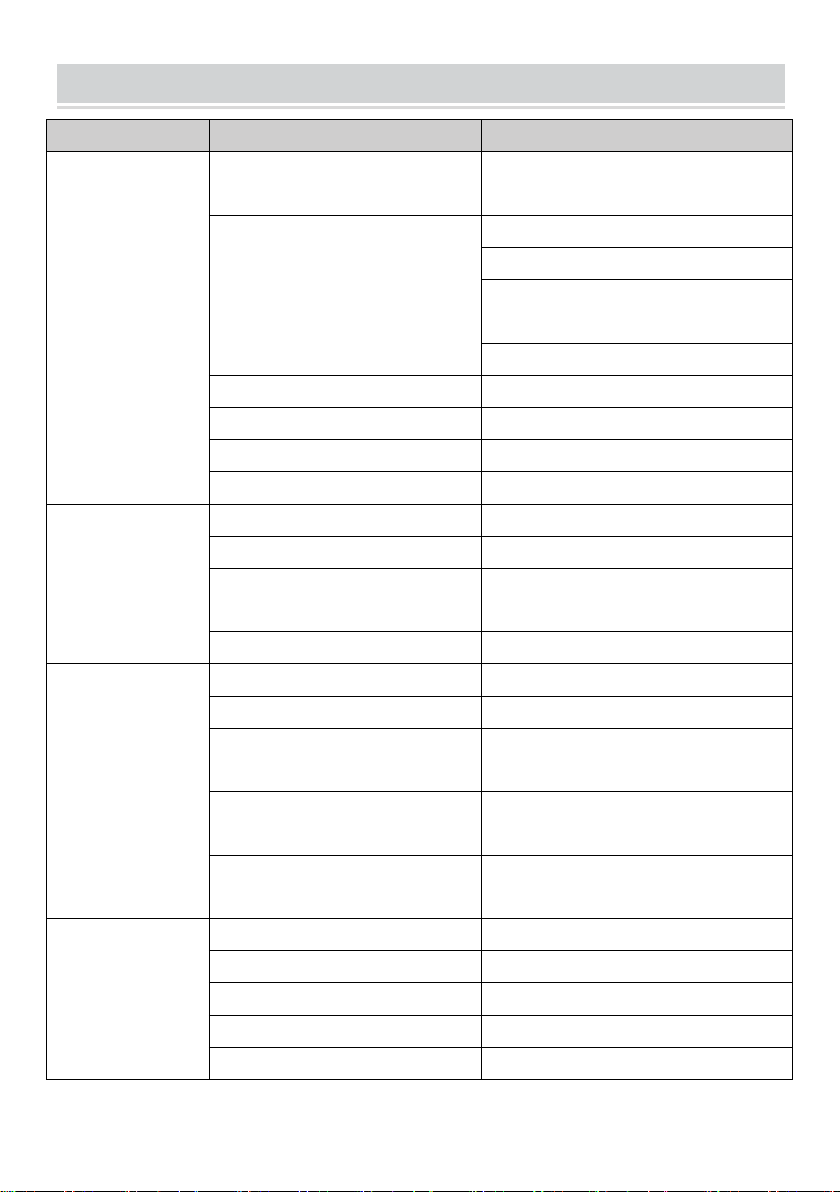
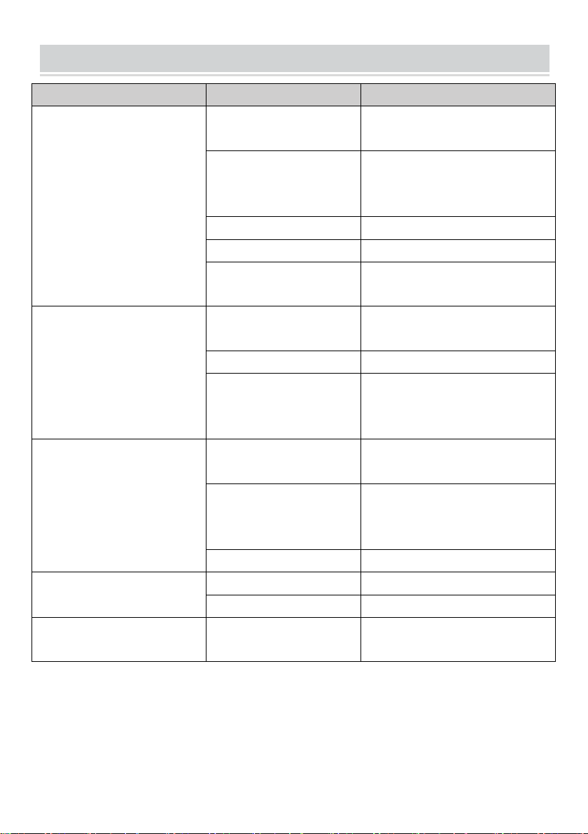
DEBUGGING
Problem
Cause
Remedy
Pump does not reach
the specified
pressures
Pump sucking air
Restore the tightness of the
intake line
Intake flow rate insufficient
Increase the size of the intake pipelines
Remove any kinks from the pipes
Increase the filter capacity or
clean the filter cartridge
Increase the rpm to the rated speed
Worn intake and delivery valves
Replace the valves(1)
By-pass valve seat worn
Replace the valve
Worn gaskets
Replace the gaskets(1)
Unsuitable,worn nozzle
Replace nozzle
Irregular variations
in pressure
Worn intake and delivery valves
Replace the valves(1)
Valves blocked by dirt
Clean the valves(1)
Air being sucked into a system
Restore the tightness of the intake pipeline
connections
Worn gaskets
Replace the gaskets(1)
Vibrations on pipes
Valves jammed
Replace the valves(1)
By-pass valve malfunction
Replace the by-pass valve
By-pass valve dump line is too small
Increase the size of the by-pass valve dump
line
Pressure damper flat
Restore pressure damper to correct inflation
pressure
Pump sucking air
Restore the tightness of the
intake line
Pressure drop
Nozzle worn
Replace nozzle
Worn intake and/or delivery valves
Replace the valves(1)
Valves blocked by dirt
Clean the valves(1)
By-pass valve seat worn
Replace the valve
Worn gaskets
Replace the gaskets (1)
(1) Operations that must be carried out at an authorized service center
- 15 -
TRQUBLE SHQOTING
Problem
Cause
Remedy
Pump noisy
Air being sucked into
the system
Restore the tightness of the
intake pipeline connections
Intake and/or delivery
valve springs broken
or collapsed
Replace the valves (1)
Valves blocked by dirt
Clean the valves (1)
Worn bearings
Replace the bearings (1)
Intake liquid
temperature too high
Reduce liquid temperature
Pump overheating
High pump operating
pressure
Reduce the pressure to the
rated values
Drive belts too taut
Restore correct belt tension
Pulley or drive
coupling
alignment poor
Restore the correct
alignment
Water in oil
Guide piston gaskets
worn
Replace the gaskets (1)
High humidity
percentage in air
Change the oil twice as often
(as stated in the "Routine
Maintenance" table)
Worn gaskets
Replace the gaskets (1)
Oil leaks from dump lines
underneath the pump
Worn gaskets
Replace the gaskets (1)
Worn pistons
Replace the pistons (1)
Oil leaks from dump lines
underneath the pump
Guide piston gaskets
worn
Replace the gaskets (1)
(1) Operations that must be carried out at an authorized service center

- 16 -
GENERAL INEORMATION
After-Sales service procedures
To request after-sales service (in the event of a pump malfunction or failure,
etc.), contact your nearest service center or the manufacturer.
When requesting after-sales services, always state the pump's data plate
data and the type of problem.
*There are any minor changes to the numbers included in the user
manual without prior notice.
Made In China