1-800-315-5533 • service@easykleen.com • www.easykleen.com
Owner's Manual
Commercial and Industrial Hot Water Gas
and Diesel Driven, Oil Fired

2
Oil Fired Gas & Diesel • Rev. 4/7/2016
Easy-Kleen Pressure Systems
1-800-315-5533
This manual contains operational information that is specific for commercial and industrial
(Bull Moose and Grizzly) hot water, gas and diesel driven, oil fired machines.
Read the following instructions carefully before attempting to assemble,
install, operate, or service this pressure washer. Failure to comply with these
instructions could result in personal injury and/or property damage.
Table of Contents
IMPORTANT SAFETY INFORMATION ............................................................................................................. 3
SPECIFICATIONS ............................................................................................................................................ 7
INTRODUCTION ............................................................................................................................................. 9
OPERATING INSTRUCTIONS ........................................................................................................................ 10
CHEMICAL APPLICATION ............................................................................................................................. 12
WINTER PUMP/ COIL PROTECTION ............................................................................................................ 13
GENERAL MAINTENANCE ............................................................................................................................ 13
MAINTENANCE CHECKLIST .......................................................................................................................... 15
GLOSSARY OF TERMS .................................................................................................................................. 17
COMPONENT IDENTIFICATION ................................................................................................................... 18
QUICK DIAGNOSTICS AND SOLUTIONS GUIDE ............................................................................................ 25
WIRING DIAGRAMS ..................................................................................................................................... 27
MANUFACTURER’S WARRANTY .................................................................................................................. 31
SERVICE MANUAL........................................................................................................................................ 33
3
Oil Fired Gas & Diesel • Rev. 4/7/2016
IMPORTANT SAFETY INFORMATION
The safe operation of our pressure washing systems is the FIRST priority of Easy-Kleen. This
will only be achieved by following the operation and maintenance instructions as explained in
this manual and all other enclosed manuals.
This manual contains essential information regarding the safety hazards, operations, and
maintenance associated with this machine. The manual should always remain with the machine,
including if it is resold.
ALL CAUTIONS AND SAFETY WARNINGS MUST BE FOLLOWED TO AVOID
INJURY OR DAMAGE TO EQUIPMENT.
THIS EQUIPMENT IS TO BE USED ONLY BY TRAINED OPERATORS AND MUST
ALWAYS BE ATTENDED DURING OPERATION.
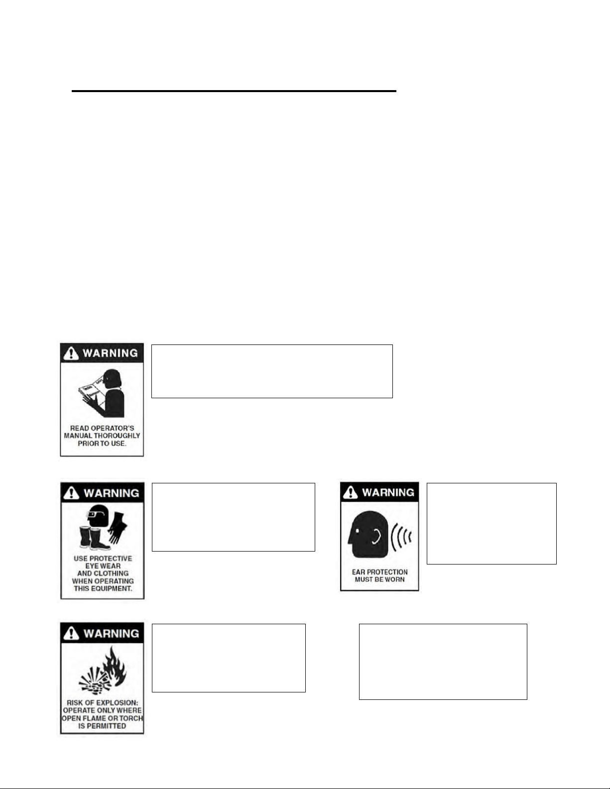
WARNING: To reduce the risk of injury,
read operating instructions carefully
before using.
WARNING: Use protective
eyewear and clothing when
operating equipment in
order to avoid personal
injuries.
1. Read the instructions in this manual carefully before attempting to assemble,
install, operate or service this pressure washer. Failure to comply with the
instructions could result in personal injury and/or property damage.
WARNING: This
machine exceeds
85db. Appropriate
ear protection must
be worn.
WARNING: Flammable
liquids can create fumes
which can ignite, causing
property damage or severe
injury.
WARNING: Risk of
explosion. Operate only
where open flame
or torch is permitted.
2. Be thoroughly familiar with all controls and know how to stop the machine in
the event of an emergency.

4
Oil Fired Gas & Diesel • Rev. 4/7/2016
.
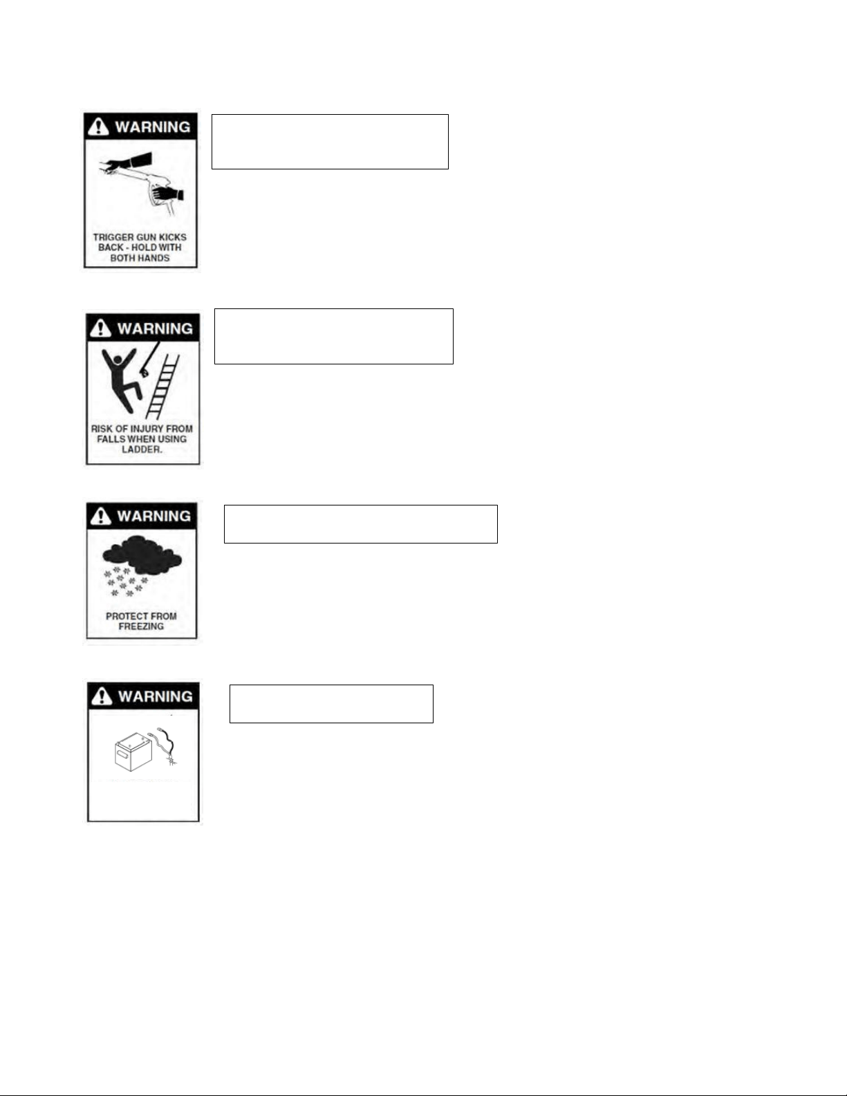
WARNING: Risk of fire. Do not
add fuel when operating machine.
3. Never use gasoline, crankcase draining, or waste oil in your burner fuel
tank. Never run pump dry or let the pump run with the trigger gun released
for more than 2 minutes. The minimum clearance to any combustible material
is 12 inches.
WARNING: Keep water spray
away from electrical wiring.
4. All electrically powered equipment must be grounded at all times to prevent
fatal electric shots. Do not spray water on or near electrical components. Do
not touch electrical components while standing in water or when hands are
wet. Always make sure machine is disconnected from power source before
servicing.
WARNING: Risk of asphyxiation.
Use this product only in a well
ventilated area.
5. Use equipment in a well-ventilated area to avoid carbon monoxide poisoning
or death. This machine must never be connected to a Type B gas vent.
WARNING: Risk of injection or
severe injury to persons. Keep
clear of nozzle spray.
6. High pressure spray can cause serious injuries. Never point pressurized
spray at any person or animal. Handle the spray assembly with care.
WARNING: Risk of
injury. Hot surfaces
can cause burns.
WARNING: Hot discharge
fluid. Do not touch or
direct discharge stream
at persons.
5
Oil Fired Gas & Diesel • Rev. 4/7/2016
7. Hold firmly to the gun and wand during start up and operation of the
machine. Do not attempt to make adjustments while the trigger gun is in
operation.
8. Make sure all quick coupler fittings are properly secured before operating
pressure washer.
WARNING: Risk of injury
from falls when using ladder.
9. Do not overreach or stand on anything unstable. Keep a good balance and
make sure to keep a steady footing at all times.
WARNING: Protect from freezing.
WARNING: Trigger gun kicks
back. Hold with both hands.
10. It is important to keep your machine from freezing in order to keep it in its
best working condition. Failure to protect your machine from freezing may
cause damage to the machine and personal injuries may occur as a result.
11. For machines with a 12 V burner: Disconnect battery ground terminal
before servicing.
12. Protect high pressure hoses from sharp objects and vehicles. Inspect
condition of hoses prior to use, or serious injury could occur.
13. Do not pass acids or other caustic or abrasive fluids through the pump.
WARNING: Risk of Injury
RISK OF INJURY

6
Oil Fired Gas & Diesel • Rev. 4/7/2016
14. Never run pump dry of water or oil or or let the pump run with the trigger gun
released for more than 2 minutes.
15. Do not attempt to operate this machine if fatigued or under the influence of alcohol,
prescription medications, or drugs.
16. Some of the maintenance procedures involved in this machine require a certified
technician (these steps are indicated throughout this manual). Do not attempt to perform
these repairs if you are not qualified.
If you need further explanation of any of the information in this manual, suspend any
activity involving the equipment and call our toll free number for assistance,
1-800-315-5533.
7
Oil Fired Gas & Diesel • Rev. 4/7/2016
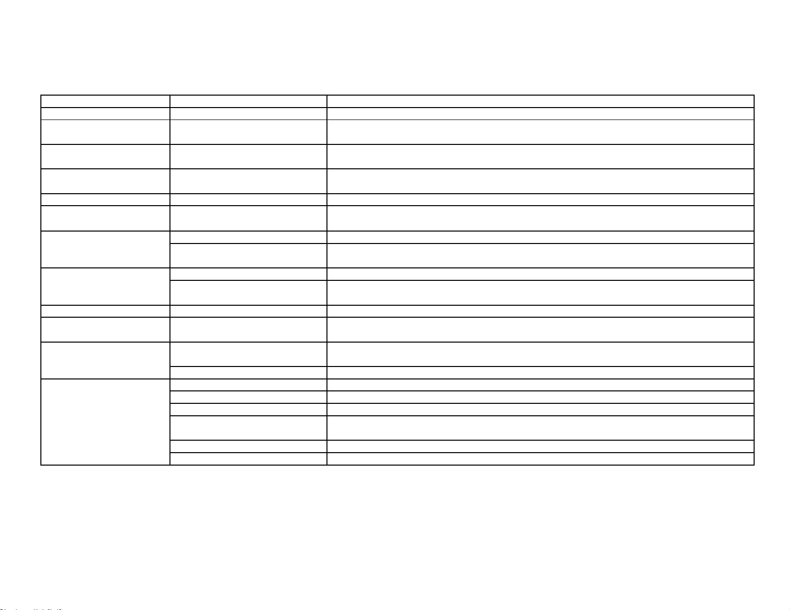
SPECIFICATIONS
Commercial Hot Water Gas - Oil Fired
MODEL
GPM
PSI
BURNER OIL
PRESSURE (PSI)
BTU
HP/ ENGINE
DRIVE
ELECTRIC
START
BURNER
EZO2703G
3
2700
130
300,000
6.5 KOHLER
DIRECT
NO
120V
EZO4035G-K-GP-R
3.5
4000
130
350,000
14 KOHLER
DIRECT
NO
120V
EZO4035G-H-GP-R
3.5
4000
130
350,000
13 HONDA
DIRECT
NO
120V
EZO4035G-K-GP-120
3.5
4000
130
350,000
14 KOHLER
DIRECT
YES
120V
EZO4035G-H-GP-120
3.5
4000
130
350,000
13 HONDA
DIRECT
YES
120V
EZO4035G-L-GP-12
3.5
4000
130
350,000
15 LIFAN
DIRECT
YES
12V
EZO4035G-K-GP-12
3.5
4000
130
350,000
14 KOHLER
DIRECT
YES
12V
EZO4035G-H-GP-12
3.5
4000
130
350,000
13 HONDA
DIRECT
YES
12V
EZO3504G-K
4
3500
130
400,000
14 KOHLER
GEARBOX
YES
12V
EZO3504G-H
4
3000
130
400,000
13 HONDA
GEARBOX
YES
12V
Commercial Hot Water Diesel - Oil Fired
MODEL
GPM
PSI
BURNER OIL
PRESSURE (PSI)
BTU
HP/ ENGINE
DRIVE
ELECTRIC
START
BURNER
EZO4035D-K-GP-12
3.5
4000
130
350,000
9.8 KOHLER
DIRECT
YES
12V
EZO3504D-K
4
3500
130
400,000
9.8 KOHLER
GEARBOX
YES
12V
*-GG – has a generator
*-ST – steam kit
Industrial Hot Water Gasoline – Oil Fired (Grizzly Series)
MODEL*
GPM
PSI
BURNER OIL
PRESSSURE (PSI)
BTU
HP/ENGINE
DRIVE
EZO3004G
4
3000
160
400,000
13 HONDA
BELT
EZO3504BG
4
3500
160
400,000
14 KOHLER
GEARBOX
EZO3504G
4
3500
160
400,000
14 KOHLER
BELT
EZO3505G
5
3500
130
500,000
20 HONDA
BELT
EZO3506G
6
3500
145
600,000
25 KOHLER
BELT
EZO3008G
8
3000
155
800,000
25 KOHLER
BELT
EZO3010G
10
3000
130
1,000,000
38 KOHLER
BELT
EZO3708G
8
3700
130
800,000
38 KOHLER
BELT
EZO5005G
5
5000
130
500,000
25 KOHLER
BELT
EZO6004G
4
6000
160
400,000
25 KOHLER
BELT
EZO6006G
6
6000
145
600,000
38 KOHLER
BELT
EZO7004G
4
7000
160
400,000
25 KOHLER
BELT

8
Oil Fired Gas & Diesel • Rev. 4/7/2016
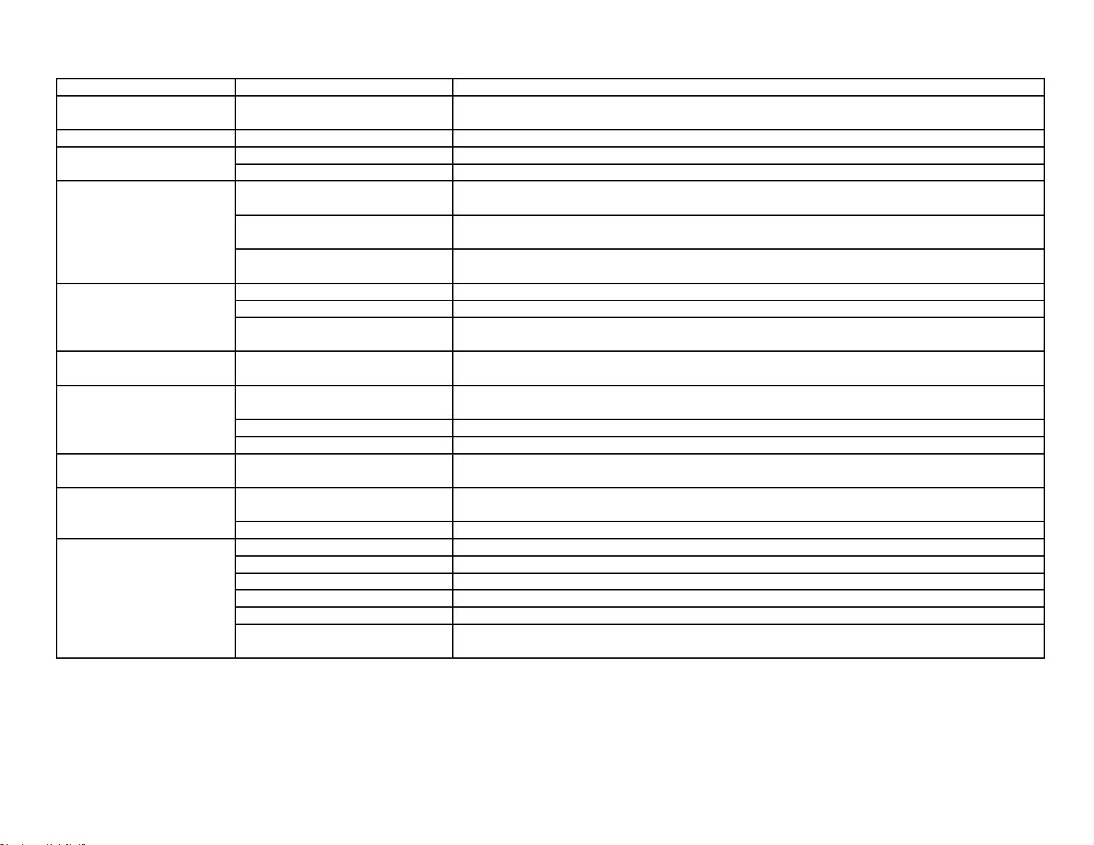
Industrial Hot Water Diesel – Oil Fired (Bull Moose Series)
MODEL
GPM
PSI
BURNER OIL
PRESSURE (PSI)
BTU
HP/ENGINE
DRIVE
EZO3204D
4
3200
160
400,000
9.8 KOHLER
BELT
EZO3506D
6
3500
145
600,000
26 KOHLER
BELT
EZO3508D
8
3500
130
800,000
26 KOHLER
BELT
EZO3010D
10
3000
130
1,000,000
26 KOHLER
BELT
EZO5005D
5
5000
130
500,000
26 KOHLER
BELT
EZO5010D
10
5000
130
1,000,000
58 KUBOTA
GEARBOX
EZO6004D
4
6000
160
400,000
26 KOHLER
BELT
EZO7004D
4
7000
160
400,000
26 KOHLER
BELT
EZO8008D
8
8000
130
1,000,000
58 KUBOTA
GEARBOX

9
Oil Fired Gas & Diesel • Rev. 4/7/2016
INTRODUCTION
Thank you for selecting a quality Easy-Kleen product. We are pleased to have you included
among the many satisfied owners of Easy-Kleen cleaning machines. Years of engineering
have gone into the development of these fine products and only top quality components and
materials are used throughout. Each machine is carefully tested and inspected before leaving
our plant to ensure years of dependable performance.
To continue to receive satisfactory performance, remembering that this machine represents a
substantial investment on your part, and if properly cared for and maintained it will return this
investment many times over. As with all mechanical equipment, your machine requires proper
operation and maintenance as outlined in this manual for maximum trouble free life.
This manual has been prepared under the direction of our engineering and service technicians.
Their experience in designing, manufacturing, installing and servicing our equipment from our
company’s inception is condensed in this manual. They know what information the end user
needs in order to get the optimum performance from their pressure washer. Please read
carefully.
This manual contains information that will be specific for your pressure washer, as well as
similar models.
Carefully review any additional manuals that have been included with your system and
follow ALL ADDITIONAL OPERATING INSTRUCTIONS AND SAFETY NOTICES.
They are specific for the quality components that have been used to manufacture your
machine and are an integral part of the operating and maintenance procedures.
The management & staff at Easy-Kleen are proud of the equipment that we design and
manufacture and we thank you for making us your # 1 choice in pressure washers. If you have
any questions please do not hesitate to call us, 1-800-315-5533.
Our goal is that you will be satisfied with the performance, quality, and service you receive from
Easy-Kleen and that if you need to replace this machine in years to come, you will give us the
opportunity to continue supplying equipment to your company.
PLEASE READ MANUALS CAREFULLY BEFORE USING MACHINE. EXAMINE
MACHINE AND CRATE CAREFULLY FOR SHIPPING DAMAGE OR MISSING
PARTS. REPORT PROMPTLY ANY SHORTAGES OR DAMAGE CLAIMS TO
FREIGHT CARRIER OR DEALER.

10
Oil Fired Gas & Diesel • Rev. 4/7/2016
OPERATING INSTRUCTIONS
1. Perform pre-start maintenance inspection on all applicable systems prior to operating the
machine. This is essential for the safe, effective and efficient operation. You will get optimum
performance from your system ONLY if these instructions and inspections are followed. Any
indication that the pressure washing system was not operated and maintained according to these
instructions may cancel the manufacturers’ warranty.
Location – Be sure to install in an area that has sufficient air ventilation to support combustion
of oil in burner.
Controls – Make sure all controls turned to the off position.
Pump – Oil level - Level the pressure washer. Be sure oil level in the pump is correct on dip
stick. If the level is low, add the correct oil to the proper level. USE ONLY SAE 30 W NON-
DETERGENT OIL OR HYDRAULIC 68. DO NOT OVER FILL.
Gas Engine - Gasoline level – The engine is a 4 cycle and uses regular octane, unleaded fuel.
DO NOT USE MIXED FUEL. Refer to the engine operation manual included with your
pressure-washing unit.
Gas Engine - Oil level – The engine is a 4 cycle and uses 10W30 detergent oil. Refer to
Glossary or engine manual.
Diesel Engine – Refer to engine operation manual included with your pressure washing unit for
oil and fuel recommendations.
Oil Fired Burner - Oil Tank Level – #2 Furnace oil is recommended for the burner oil tank, as
it burns cleaner and the burner requires less maintenance. Diesel fuel may be used as an
alternative. Do not overfill burner tank.
Visually inspect all electrical components to assure they are in good condition, showing
No signs of exposure, breakage or splicing.
Visually inspect all hoses, nozzles and guns to assure they are in good condition. If
replacements are necessary they must be rated to withstand the machines operating
pressure and temperatures.
2. Attach high-pressure hose to hot water outlet quick connector. Attach the other end of high
pressure hose (with quick coupler) to spray gun. Ensure that quick disconnect connections are
tightly locked together. Apply a sharp pull on hose to confirm they are secured.
Attach wand nozzle specific to task requirements (i.e. chemical or pressure wash).
[Quick Coupling Operation – Pull back sleeve end and insert male end into nozzle quick coupler,
release sleeve and confirm connection by pulling on the nozzle].

11
Oil Fired Gas & Diesel • Rev. 4/7/2016
3. Attach water source to water inlet located on pump. The water source must be attached with a
good quality standard garden type hose (1/2” minimum is required). Connect male fitting into the
female pump inlet fitting. Make sure that the inlet screen/filter is intact and fitted correctly. Turn
on water source. WATER MUST BE IN SUFFICIENT SUPPLY, AND PRESSURE MUST BE
BETWEEN 20 –60 PSI TO ENSURE PROPER AND SAFE OPERATION. Specific attention
should be given if using a well water supply. Ensure water is flowing from end nozzle with the
trigger gun pulled. Deplete system of all air.
4. Start Gas/Diesel Engine
Refer to instructions in engine manual. MAKE SURE THAT THE ENGINE EXHAUST IS NOT
FACING ANY FLAMMABLE MATERIALS.
5. Burner operation
Be sure water is flowing through water heater coil before turning on BURNER switch. Turn
thermostat to desired temperature. Burner will ignite and remain in operation as long as there is
sufficient water flow to satisfy the pressure switch and temperature control.
IF YOU EXPERIENCE IGNITION FAILURE, DO NOT ATTEMPT TO RESTART
BURNER! EXCESS FUEL AND VAPORS MAY HAVE ACCUMULATED AND THE
CHAMBER MAY BE HOT. THE UNIT MUST COOL DOWN BEFORE RESTART CAN
BE ATTEMPTED.
Warning: Condensation on Coil
When cold water is being pumped through the heater coil and the burner is firing, condensation
may form at times on the coil and drip down into the burner compartment. This can be
particularly noticeable on cold, humid days giving the false appearance of a leaking coil. A
leaking coil or system will be evident if the pump keeps cycling with the trigger released. The
pump head pressure should read ‘0’.
Electrically Operated Burners – These models generate 12V from the gasoline engine and
provide the necessary power for the burner. IF YOU REQUIRE UPGRADES OR
MODIFICATIONS TO YOUR EXISTING ELECTRICAL SYSTEM IN ORDER TO
OPERATE YOUR PRESSURE WASHER, THEY MUST BE PERFORMED BY A LICENSED
ELECTRICIAN AND BE COMPLETED IN ACCORDANCE TO ALL APPLICABLE CODES
IN YOUR AREA OF OPERATION. The power supply must be adequate for your specific unit.
Make sure to verify the data plate for your machine’s specific requirements (i.e. voltage,
amperage, etc.).
6. Pressure adjustment - The pressure regulator (unloader) is located on the pump (see pages
19, 21 & 23 diagrams. It controls the pressure being generated by the pressure washer. This
regulator may be adjusted to the desired pressure by turning the adjustment knob. Turning the
adjustment knob clockwise will increase the pressure. NEVER OPERATE SYSTEM AT A
HIGHER PSI THAN THE MAXIMUM RATING. This machine has been adjusted to operate
at a specific maximum pressure as per the machine specifications. Pressure may be reduced for
lighter use by turning the Pressure Regulator/Unloader counter clockwise. If continuing to turn
the unloader clockwise does not increase the pressure, then this implies the maximum has been
reached for

12
Oil Fired Gas & Diesel • Rev. 4/7/2016
the system. Any further turning of the unloader will cause the pressure to spike when the wand
trigger is released, resulting in possible damage to the machine. To avoid this effect, loosen the
unloader (counter-clockwise) until the pressure just starts to drop (see pump head pressure
gauge) and until it no longer exceeds the maximum pressure rating for the machine.
7. You are now ready to start the cleaning operation - Pull trigger on the pressure wand
assembly to start cleaning. To stop the pressurized water, release the trigger. DO NOT
LEAVE UNIT RUNNING WHEN NOT IN USE.
8. To stop Burner operation – Turn BURNER switch to ‘PUMP’ (or to ‘OFF’ for Auto start
stop models) and run pump for two minutes with trigger gun pulled to allow coil to cool down.
After cooling period is complete, turn off main power to motor by turning BURNER switch to
‘OFF’ (turn PUMP switch to ‘OFF’ if equipped with auto start stop). Squeeze and release the
trigger for the second time in order to relieve the pump system of pressure.
9. Prior to storage – Inspect pressure washer for any damage or required maintenance. If your
machine is to be exposed to cold weather, please refer to winter pump/coil instructions found in
this manual. If possible, do not allow unit to remain outside in the elements.
10. Warning – If unit is left running while not in use, pump damage may occur. Do not leave
unit running while not in use!
11. Battery Specifications for electric start systems only – Rating: 165CCA, 190 CA or better,
dimensions: 8” x 5” x 6” (applies to commercial units).
CHEMICAL APPLICATION
Downstream Chemical Injection: Standard (Direct Drive Units)
High Pressure Soap (Optional Feature)
NOTE: Do not remove back flow preventer as chemical may flow back into potable water
source. For standard chemical injection, ensure the black nozzle is properly fitted at the
end of the wand. The chemical injector will not function if this nozzle is not fitted.
1. Chemical preparation – Select detergent/chemical that best suits your cleaning task. Prepare
dilution according to the manufacturer’s instructions. The volume of chemical being used may be
adjusted at valve located on the chemical injector. Note: for EK Pumps, the volume is preset and
cannot be adjusted.
2. Insert the intake hose, located on the chemical injector at the pump, into the chemical being
used.

13
Oil Fired Gas & Diesel • Rev. 4/7/2016
3. Fit black nozzle on the standard wand, or for the dual wand, turn adjustment knob on, and
adjust for required flow rate. For high pressure soap systems, the black nozzle is not needed; use
one of the other wand nozzles.
4. To apply chemical, engage trigger on pressure wand assembly. Turn chemical injector’s nipple
to adjust flow. For the high pressure soap systems, open ball valve and engage trigger.
5. Chemical can now be applied through pressure wand assembly. It will take 5 – 15 seconds for
chemical to travel to spray nozzle. The volume of chemical being used may be adjusted at the
chemical injector.
6. For best results apply chemical from bottom to top, and allow for proper penetration time prior
to rinsing. Do not allow chemical to dry. Rinse from bottom to top and then top to bottom.
WINTER PUMP/ COIL PROTECTION
The following procedure MUST be used when the pressure washing
unit is stored at temperatures below freezing.
1. All water must be drained or blown (via compressed air) from system. Connect a short piece
of male fitted ½” garden type hose on to the female inlet on the pump.
2. Place the open end of the hose into a wide mouthed container of full strength, winter rated,
vehicle windshield washing fluid or Anti-Freeze, RATED FOR MINIMUM -40°C.
3. Connect the pressure wand assembly.
4. Start the engine and engage the trigger on the pressure gun. Operate the system until the fluid
runs the same color as the windshield washing fluid. Your machine is now prepared for storage.
5. Disconnect fluid supply, blow out with compressed air, and cap end.
GENERAL MAINTENANCE
Burner Maintenance
NOTE: Repair of the burner is to be done by authorized and trained burner professionals
only.
The oil filter cartridge should be replaced every year to prevent fuel contamination and plugging
of fuel pump and nozzle of oil burner. The nozzle should also be replaced at least once every
year or twice if used daily and if poor combustion begins to occur. See the included burner
manual for more information on burner.

14
Oil Fired Gas & Diesel • Rev. 4/7/2016
Final adjustments to burner include fuel pressure adjustment for controlling water temperature
(tighten fuel pressure adjustment screw slightly to increase desired output temperature) and air
band adjustment for combustion efficiency. A combustion test kit should be used for these final
adjustments. Check SPECIFICATIONS chart (page 7) for the burner oil pressure corresponding
to your model and be sure not to exceed this pressure. See included burner manual for more
information and a parts break down of the burner.
If the burner floods with oil: run machine with heat on until all excess oil is burned off (this
can take up to a couple of hours). If excess oil is not properly dealt with, the ceramic casing can
absorb excess oil, causing a fire hazard. DO NOT LEAVE MACHINE UNATTENDED WHILE
MACHINE IS FLOODED.
General Maintenance and Care
If the water heater is likely to be exposed to freezing weather then it should be winterized
according to the winter pump/coil protection procedure in the previous section. Alternate
methods may not completely protect the components. Damage from freezing is not a warrantable
item.
Water Condition
Use a softener on your water system if local water is known to be high in mineral content. The
advantages of soft water are very beneficial: prevents scale buildup in heater coil, cleans better
with considerably less detergent, prevents streaking on painted surfaces and glass when rinsing.
Descaling Heater Coil Procedure
NOTE: Descaling of the heater coil is to be done by authorized and trained professionals
only.
The best way to acidize the coil is with a circulation pump capable of handling acids.
1. Fill a plastic container with a suitable acid diluted with water to desired strength.
2. Connect discharge from the circulating pump to the hot water outlet on the water heater with a
suitable hose. Connect the inlet of the circulating pump to the acid container with suction hose
from the pump module and use it as a return hose to the acid container. As acid dissolves the
scale it becomes neutralized, so about every five minutes add more acid to the container until all
the scale has been removed from the coil. Flush out coil thoroughly with water after descaling.

15
Oil Fired Gas & Diesel • Rev. 4/7/2016
MAINTENANCE CHECKLIST
Maintenance for Pump
Daily
1. Check oil for proper level and adjust accordingly.
2. Examine the quality of the oil.
3. Check pump for oil and/or water leaks.
4. Inspect and clean inlet filters.
Weekly
1. Examine all fittings, components, hoses, connections, and nozzles for damages, loose
parts, or leaks. – Replace accordingly—
Recommendation for Oil Changes and Component Replacement
1. Change the oil in the pump after the first 50 hours and every 500 hours after the initial
oil change. Use SAE 30 W Non-Detergent for GP Pumps and Hydraulic 68 for EK
Pumps.
2. Change all other components on the pump as needed.
Maintenance for Gasoline Engine
Daily
1. Check oil for proper level and adjust accordingly.
2. Examine the quality of the oil
3. Examine the air cleaner element
Weekly
1. Examine engine components for damages, loose parts, or leaks.

16
Oil Fired Gas & Diesel • Rev. 4/7/2016
Recommended Schedule for Oil Changes and Component Replacements
1. Change engine oil after first 5 hours and every 100 hours after the initial oil change.
Use 10w-30 engine oil.
2. Replace Spark Plug every 100 hours.
3. Change air cleaner element every 100 hours.
4. Check fuel filters every 300 hours.
5. Change all other components on engine as needed.

17
Oil Fired Gas & Diesel • Rev. 4/7/2016
GLOSSARY OF TERMS
PSI – Pounds per square inch. Pressure washers are designed and rated to operate at a specific
PSI. Operating at pressures exceeding the maximum rating could result in damage to the unit
and/or SEVERE PERSONAL INJURY.
GPM – Gallons per minute. The orifice on the pressure wand assembly has been selected to
deliver up to the maximum GPM for your machine.
PRESSURE WAND ASSEMBLY – This refers to the gun, wand, and nozzle.
PUMP – The pump moves the water through the system and delivers it to the pressure wand
assembly.
UNLOADER VALVE – Is a valve located at the head of the pump for unloading water back
into the bypass when the trigger gun is shut off. It also reduces the load on pump when gun is
off.
OIL, PUMP – The oil used within the pump to lubricate its operation. Important to use only
SAE 30 W Non Detergent (GP Pump) or Hydraulic 68 (EK Pump) in the pump (see diagram).
OIL, GASOLINE ENGINE – Gasoline Engines need appropriate lubricant. Use 10W30
detergent oil.
BURNER – The burner heats the water in hot water pressure washers. It is located under the coil
and may be powered by furnace oil or diesel fuel.
BACK FLOW PREVENTER – Device to prevent flow backwards into potable water supply.
MAXIMUM WORKING PRESSURE The water heater coils are designed to operate safely at
normal working pressure. Each machine is equipped with a safety pressure relief valve which
prevents over pressurization of the high pressure system. It is an important safety device and
must not be tampered with in any way.
TEMPERATURE CONTROL- The water heater is equipped with a temperature control which
shuts down the burner in the event of excessive outlet temperature caused by insufficient water
flow through the heater coil. Do not set thermostat above 195°F
PRESSURE SWITCH - A high pressure switch is used to control the burner. It is part of the
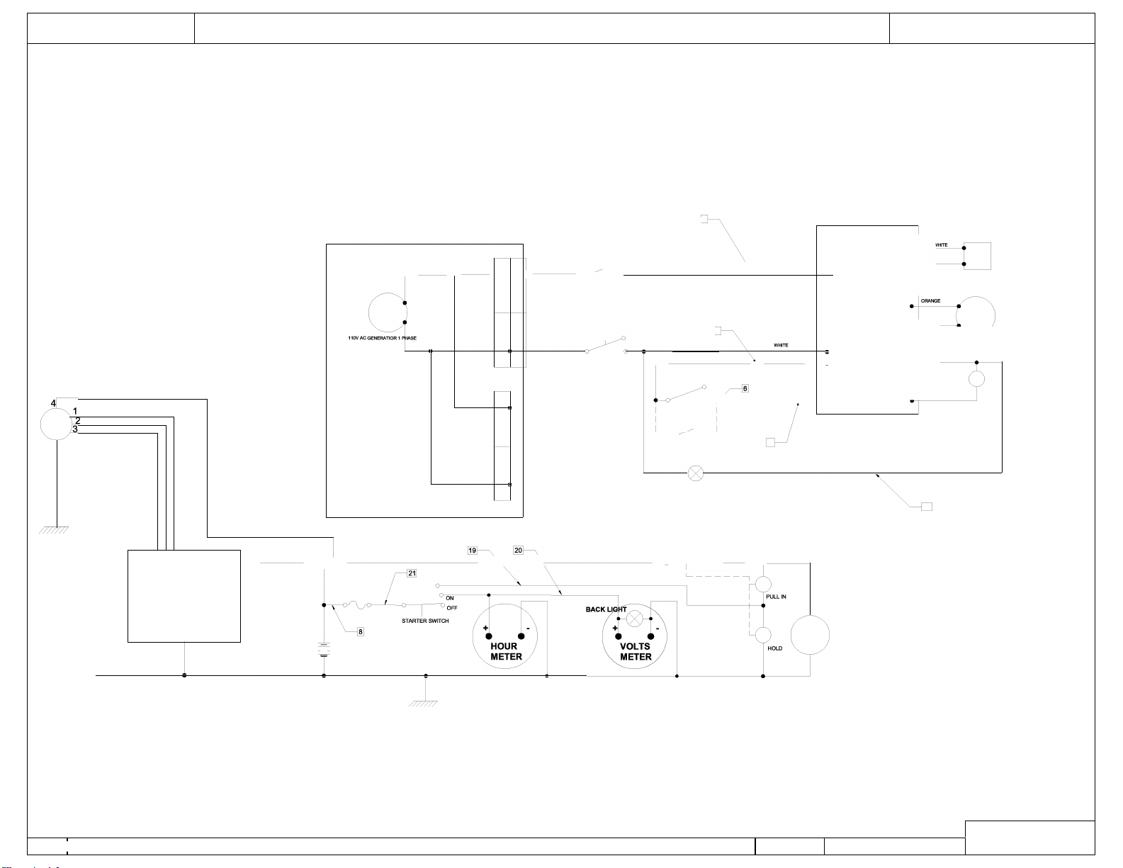
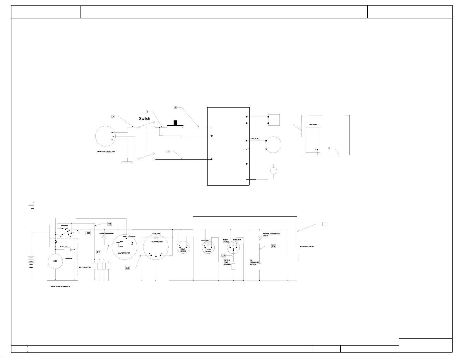
burner control system (see diagrams pages 19, 21 & 23).
FLOW SWITCH – A flow switch is installed on the outlet of the high pressure pump and will
shut off the pump and motor in the absence of water flow as well as turning it back on when flow
is detected (by squeezing the trigger).
18
Oil Fired Gas & Diesel • Rev. 4/7/2016
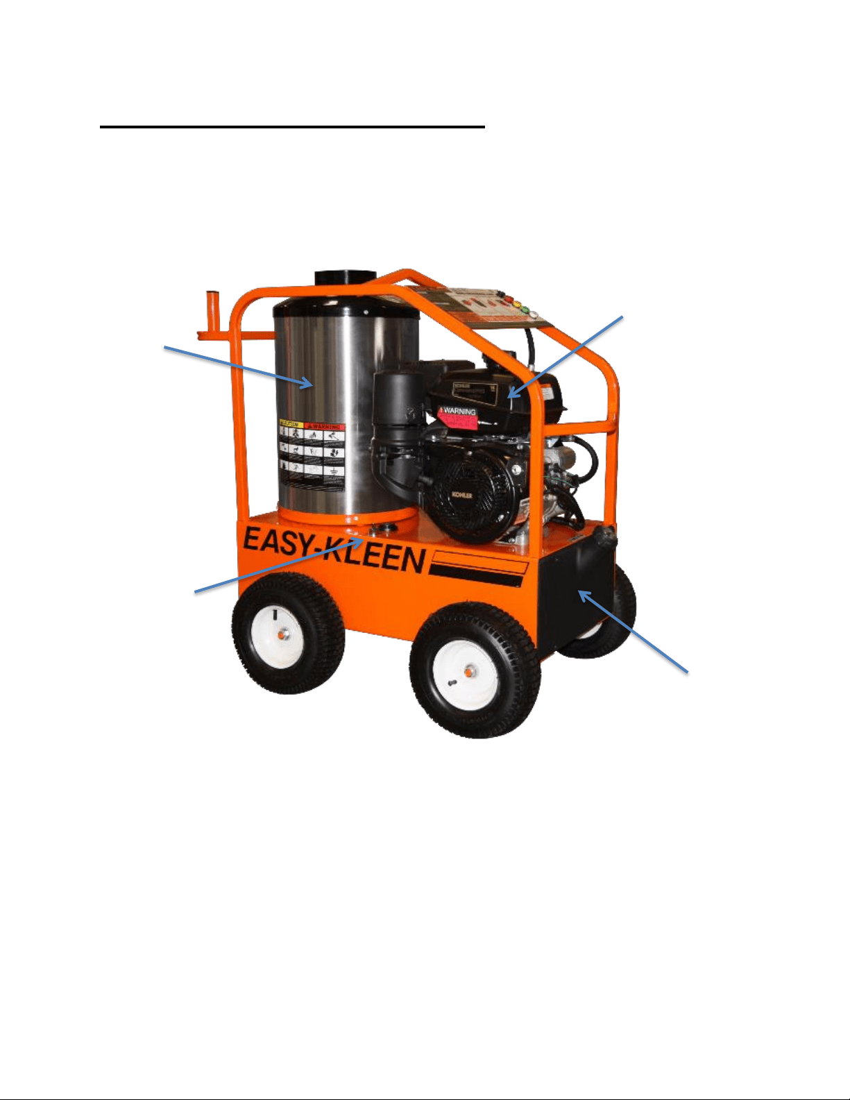
COMPONENT IDENTIFICATION
Commercial Model:
10 Gallon Poly Fuel Tank
Burner Switch and
Thermostat
Gasoline Engine
Coil Skin
19
Oil Fired Gas & Diesel • Rev. 4/7/2016
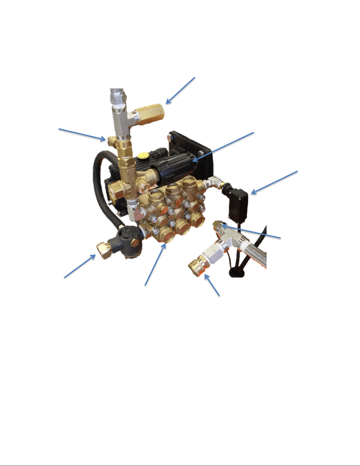
Direct Driven Pump Assembly:
Chemical
Injector
Water Inlet
Unloader
Burner Control
Pressure Switch
Safety Relief Valve
Temperature
probe
Hot Water Outlet
Quick Connector
Water Pump

20
Oil Fired Gas & Diesel • Rev. 4/7/2016
Bull Moose Series Industrial Model:
*Model shown with optional steam kit.
Hot Water Outlet
Flue Outlet
Water Pump
Instrument Panel
Water and
Steam Inlet
Coil Skin
Diesel Engine
12V Battery Box
20 Gallon Poly Fuel Tanks
(For Burner and Engine)
Temperature Probe
Flow Switch

21
Oil Fired Gas & Diesel • Rev. 4/7/2016
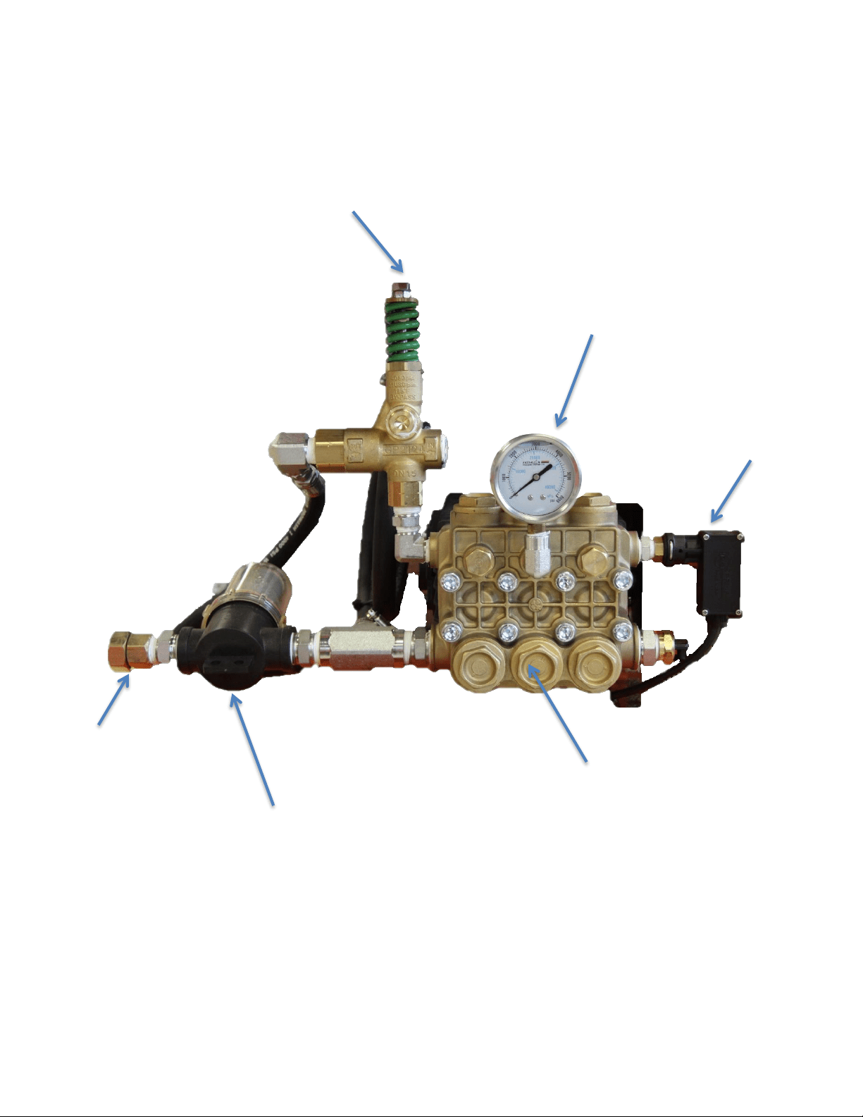
Bull Moose Pump Assembly with Optional Steam Kit:
Unloader for Pump
Pump Head
Pressure Gauge
Burner Control
Pressure Switch
Hose to
Steam Valve
Water Filter
Water Inlet
Water Pump
Unloader for
Steam Kit
Hose from
Steam Valve

22
Oil Fired Gas & Diesel • Rev. 4/7/2016
Grizzly Series Industrial Model:
Water Pump
Gasoline Engine
Coil Skin
10 Gallon Poly Fuel Tank
(For Burner)
10 Gallon Poly Gas Tank
(For Engine)
Burner Switch &
Adjustable Thermostat
23
Oil Fired Gas & Diesel • Rev. 4/7/2016
Grizzly Series Pump Assembly:
Water Inlet
Water Filter
Pump Head
Pressure Gauge
Unloader
Water Pump
Burner Control Pressure
Switch
24
Oil Fired Gas & Diesel • Rev. 4/7/2016
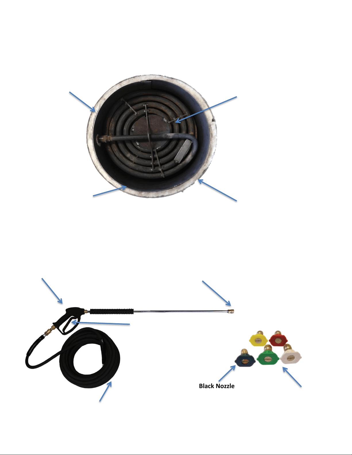
Hot Water Tank Interior (Top Cover Removed):
Pressure Wand Assembly:
Wand Nozzles
Black Nozzle for
Downstream Chemical
Application
Nozzle Quick
Coupler
Spray Gun
High Pressure Hose
Trigger
Coil
Coil Skin (outer
stainless steel layer)
Inner Steel
Layer
Ceramic
Casing
25
Oil Fired Gas & Diesel • Rev. 4/7/2016
QUICK DIAGNOSTICS AND SOLUTIONS GUIDE
PUMP
TYPE OF OIL
EK Pump
Hydraulic 68 (650ml)
GP Pump
30W SAE Non-Detergent
PROBLEM
POSSIBLE CAUSES
SOLUTIONS
PRESSURE
No pressure
or
Very low pressure
Metal in oil
- Examine oil in pump to see if there is metal in oil.
- If you find traces or pieces of metal, your pump
has damaged components.
Dirt in water
- Verify if there is dirt in nozzle tip or in valves in pump.
- If nozzle is plugged, clean or replace it.
- If valves in pump are clogged, clean valves.
- If valves in pump are damaged or pitted, replace
valves.
Wrong nozzle size
- Make sure you have the right nozzle size. The black
nozzle will drop pressure in order to use chemical injector
and is only for soap or chemical. If you are not using soap,
use a different color.
Pressure too high
Wrong nozzle size
- Make sure you have the right nozzle size.
Unloader adjusted improperly
or damaged
- Check pressure of pump with a pressure gauge and adjust
to desired pressure.
- If you cannot reduce pressure, replace unloader.
LOSS OF BATTERY CHARGE (12 VOLT SYSTEM)
Burner fan does not
shut down or burner
fan starts up when
machine is not in use
Thermostat is stuck or damaged
- Make sure thermostat is working properly. Take dial off
thermostat button. Turn the 2 screws about a quarter of a
turn to the left (counterclockwise). Put dial back on. Try to
shut off thermostat.
- If you don’t hear a click when you turn the
dial completely over, replace thermostat.
NOTE : The newer 12 volt models now have an on/off
switch that is designed to cut off current between the
battery and burner in order to preserve the battery’s
charge. If you have a model that does not have this switch,
please call us for more info.

26
Oil Fired Gas & Diesel • Rev. 4/7/2016
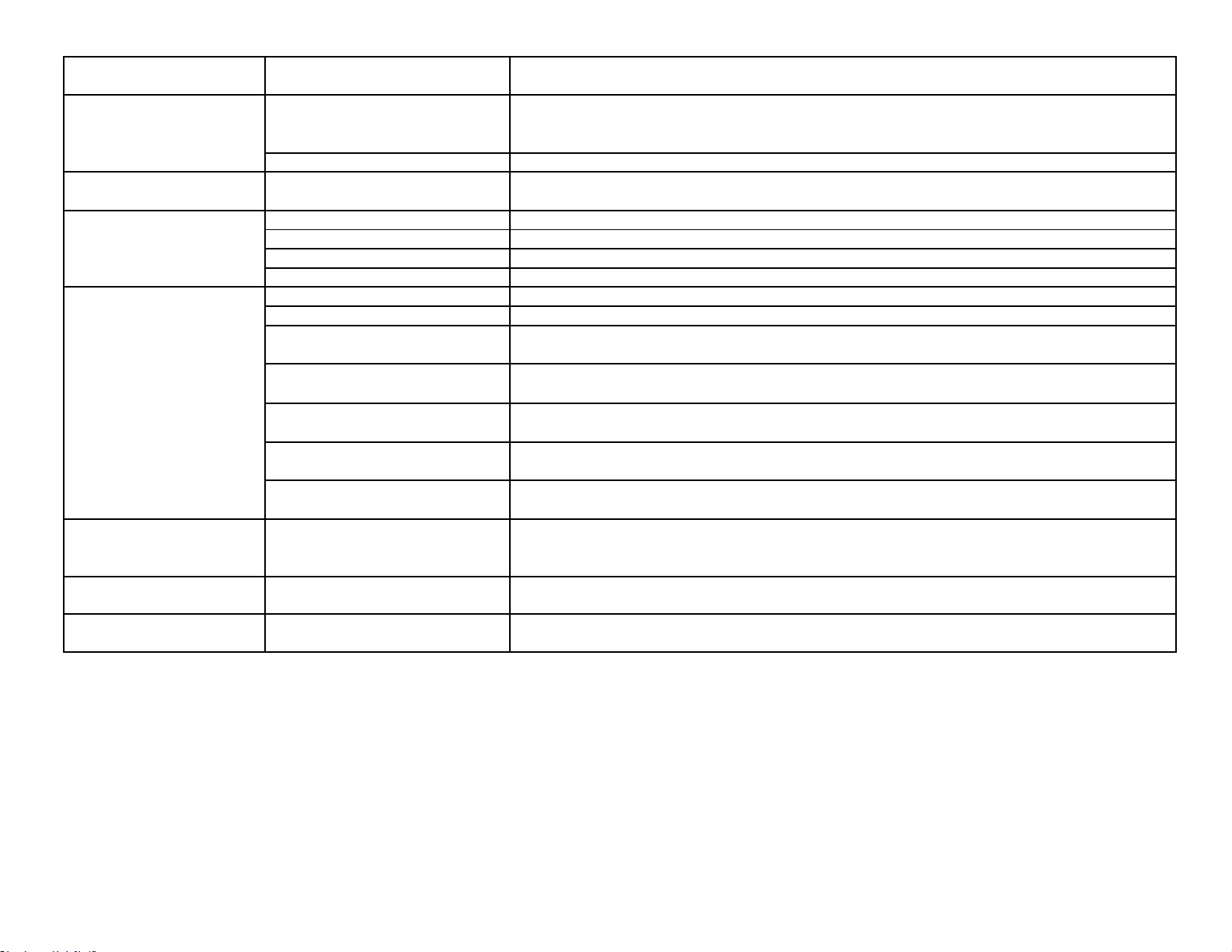
PROBLEM
POSSIBLE CAUSES
SOLUTIONS
BURNER
No hot water
Dead battery
-
Make sure your battery is fully charged.
- If the battery’s charge is not full, please
replace or re-charge your battery.
Damaged thermostat
- Make sure thermostat is connected properly.
- If burner fan does not come on when you
turn thermostat dial, replace thermostat.
Damaged pressure switch
- Make sure pressure switch is connected properly
to burner unit. Take cover off pressure switch by
unscrewing the 4 screws on the front part of the
switch (switch is located on pump). Without
touching the contacts that conduct current, push on
the little button found on the micro switch (button
is located directly above the part that attaches
directly into pump).
- If burner comes on, replace pressure switch.
- If burner does not come on, make sure there
is current going through switch (consult a
professional for this if you do not know how
to do this properly as you can get severely
injured by the electrical current connected to
your machine). If current properly flows
through pressure switch to burner, check
ignitor.
Damaged ignitor
-
Please call a repair center for help to conduct
tests on the ignitor.
-
If you see vapor coming out the top of
the coil when you try to turn the burner
on while the machine is in use, fuel is
passing through the system properly but
the ignitor is unable to produce a spark.
Replace the ignitor.
-
If you don’t see vapor, check the fuel
line.
Plugged filter or no fuel
-
Make sure you have enough fuel in the tank.
- If you have fuel, make sure the filter and
fuel line are not plugged or damaged.
FILE
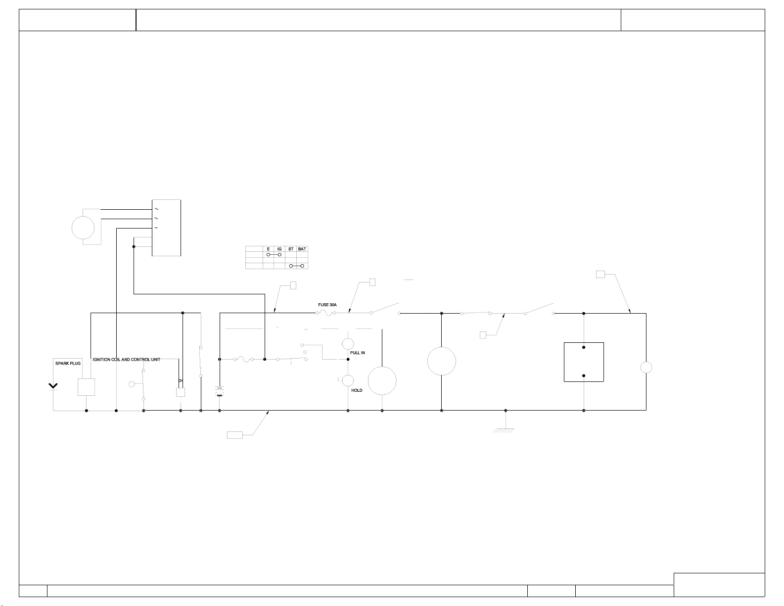
EASY KLEEN PRESSURE SYSTEMS LTD
CIRCUIT DIAGRAM
GAS ENGINE WITH ELECTRIC START AND 12V DC BURNER OIL FIRED
+
8
9
\
�--
_____ :
L _________
I
=
GND
18
6
DATE
23 DEC 2015
DWING
0305
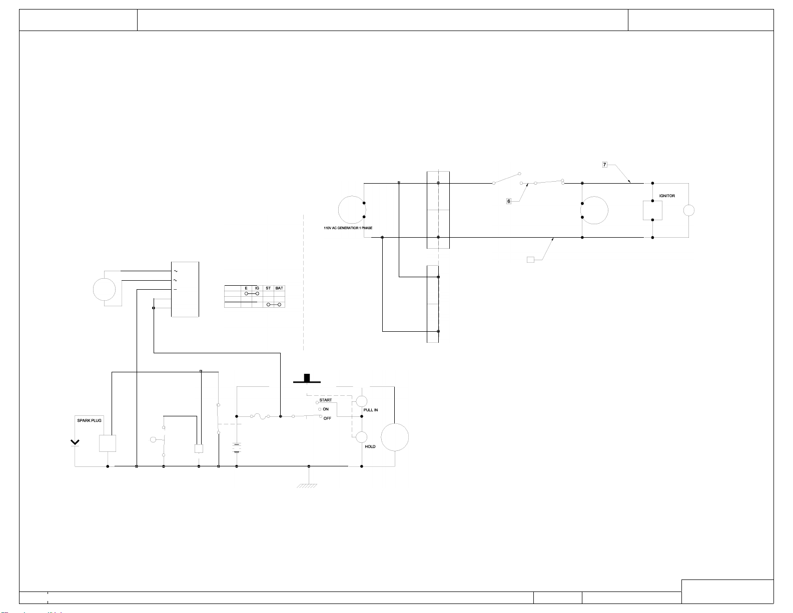
+
,
ON
L ___________________ �
FUSEA
=
12
L1
1 0 BURNER MOTOR
TERMOSTAT
L2
L2
L1
L2
DWING
\17
r
1 0 BURNER MOTOR
:v
I
11
496
---
=
22
0989
120V AC ELECTRICAL CIRCUIT
Limit
l2
IGNITOR
l2
12V DC ELECTRICAL CIRCUIT
:
TT
26
MANUFACTURER’S WARRANTY
Thank you for your purchase of an Easy Kleen pressure cleaning system. All original
equipment are warranted for a specific period and on the conditions set forth, that the
product is free from defects in materials and workmanship as follows:
7 Years Parts
1 Year Labor
Heating Coils
1 Year over 5100 PSI, Lifetime Limited
under 5100 PSI, 1 Year Labor
Honda Engine *Kohler Engine * Others
2 Years or as
otherwise stated by the engine
manufacturing policy
Electric Motor/Generators
2 Years/1 Year Warranty from
individual manufacturer of
component
Lifetime Limited Warranty
Frame and Body Materials
Burners: fuel pumps, ignitor, fuel
solenoid coil, burner motor, gas valve
1 Year Parts
1 Year Labor
Pump: Crankshaft, Manifold, Crankcase,
Bearings, Connection Rods
Electric Components: switches, GFCI, therm-
ostats, transformers, flow & pressure switch
Accessories, Unloader, Safety Valves, Pulleys,
Flow & Pressure Switch, Thermometers
90 day, Manufacturing Defect
90 day, Manufacturing Defect
Wear Items: trigger guns, wands, water
strainers, filters; seals, lights, gaskets; belts,
check valves; nozzles; o-rings; quick couples,
packings and seals on wet-end of pump, high
pressure discharge hose; chemical injectors
and fuel filters
90 day, Manufacturing Defect
NOTE* Due to original equipment manufacturer’s requirements, Easy Kleen is not permitted to perform warranty
repairs or claims for electrical motors, gas, or diesel engines. Please contact Easy-Kleen service department for
a local warranty representative.
LIMITATIONS OF LIABILITY
Easy Kleen liability for special, incidental, or consequential damages is expressly disclaimed. In no event shall
Easy Kleen’s liability exceed the purchase price of the product in question. Easy Kleen makes every effort to
ensure that all illustrations and specifications are correct, however, these do not imply a warranty that the
product is merchantable or fit for a particular purpose, or that the product will actually conform to the
illustrations or specifications. Our obligation under this warranty is expressly limited at our option to the
replacement or repair at our manufacturer location, is such part or parts at inspection shall disclose to have
been defective. Easy Kleen does not authorize any other party, to make any representation or promise on behalf
of Easy Kleen or to modify the terms, conditions, or limitations in any way. It is the buyer’s responsibility to
ensure that the installation and use of Easy Kleen products conform to local codes. While Easy Kleen attempts
to ensure that its products meet national codes, it cannot be responsible for how the customer chooses to use or
install the product. THE WARRANTY CONTAINED HEREIN IS IN LIEU OF ALL OTHER WARRANTIES,
EXPRESSED OR IMPLIED, INCLUDING ANY IMPLIED WARRANTY OF MERCANTABILITY OR FITNESS FOR A
PARTICULAR PURPOSE ARE EXPRESSLY LIMITED TO THE DURATION OF THIS WRITTEN WARRANTY.
Easy Kleen reserves the right to make any changes to an Easy Kleen product at any time without incurring any obligation
with respect to any product previously, ordered, sold, or shipped.

WARRANTY REPAIRS
Warranty claims must first contact Easy Kleen’s Service Department to be issued a pre-
authorized repair number (PARN). You will need a copy of your invoice and the
equipment serial number.
If new parts are needed, they will be invoiced to you as normal. Defective parts are to be
sent to us PREPAID for warranty and consideration. If a part is found to be defective, a
credit will be issued to cover the costs of parts and shipping. All work is be performed at
the manufacturers’ place of business when returned PREPAID. This warranty will not
cover labor if warranty work is conducted at the customer’s place of business. Road
service will be charged at the normal rate in these situations.
WARRANTY DOES NOT COVER:
• Abnormal wear-and-tear: Our warranty covers material and manufacturing defects
only
• Components or other devices not manufactured by Easy Kleen including, but not
limited to gasoline, diesel engines, electric motors, generators, pumps, etc.
• Pickup and/or delivery of the equipment.
• Rental or replacement equipment during the repair period
• Overtime labor charges
• Freight charges for replacement parts (customer responsibility)
• Travel time or mileage
• Service calls
• Transportation of equipment for service
• Consequential Damage or Liability that occurs as a result of original defect.
WARRANTY DOES NOT COVER DEFECTS CAUSED BY:
• Improper or negligent operation or installation, accident, abuse, misuse, neglect,
unauthorized modifications, including, but not limited to, the failure of the
customer to comply with recommended product maintenance schedules.
• Improper repairs
• Neglected maintenance/incorrect operation (specified in the Owner/Operator’s
Manual
• Unapproved devices or attachments
• Water sediments, rust corrosion, thermal expansion, scale deposits or a
contaminated water supply or use of chemicals not approved or recommended by
Easy Kleen Pressure Systems Ltd.
• Improper voltage, sudden voltage spikes or power transients in the electrical
supply
• Usage which is contrary to the intended purpose of the equipment
• Natural calamities or disasters including, but not limited to, floods, fires, wind,
freezing*, earthquakes, tornados, hurricanes and lightning strikes
*Includes damage done to components that come in contact with water as a result
of freezing in a non-winterized machine.

Easy-Kleen Pressure Washers
Service Manual
This manual is intended for technical personnel to assist in the diagnosis
and repair of issues with pressure washers.
This manual is not intended for use by non-technical personnel.
It is advised to always refer to competent technical personnel when
repairs are advised to avoid equipment damage or potential personnel
injury.
If you have any technical questions please do not hesitate to call us at
1- 800-315-5533.
POWER SYSTEM DIAGNOSTICS - Gas Motor Not Starting
PROBLEM
POSSIBLE CAUSE
SOLUTION
Gas motor not starting
Fuel
Check to see if proper fuel levels are maintained
No ignition
Check ignition by removing spark plug from cylinder. If electric start, try starting using the recoil starter.
Electric Starter/Battery
Recharge or replace battery.
Fuse blown in key switch
18 amp engine, open key switch, replace 30 amp fuse
Spark Plug - strong gas
smell
Flooded
Wait 5 minutes before attempting to restart.
No ignition
Check ignition by removing spark plug from cylinder. If electric start, try starting using the recoil starter.
Bad plug
Check spark plug and replace if necessary. Carbon deposits can indicate a fouled plug or too much
fuel.
Plug does not fire
Poor connection
Inspect the ignition connection.
Bad magneto
Check the source of spark plug for engine ignition.
Bad ignition system
Poor connection
Check the source of spark for the engine ignition.
Spark Plug - no gas smell
No fuel to cylinder
Check fuel delivery from carburetor to cylinder. Check carburetor float bowl for fuel.
Fuel line restricted
Inspect fuel line to carburetor for restrictions or clogging. Flexible line may be kinked.
Stuck carburetor float
Unstick float
Clogged carburetor needle valve
Unclog needle valve.
Bad fuel pump
Replace fuel pump.
FLUID SYSTEM DIAGNOSTICS - Flow and Pressure
PROBLEM
POSSIBLE CAUSE
SOLUTION
No Flow
No power
Make sure pump is operating. Check drive belts and couplings, make necessary adjustments.
Trigger gun valve
Check trigger gun, repair or replace.
No water source
Ensure water supply is not restricted and hoses are in good repair and not kinked.
Clogged spray nozzle
Check spray nozzle, repair or replace.
Clogged inlet filter
Check inlet filter, repair or replace.
Float Valve stuck (optional)
Float valves can become stuck in the "UP" position. Manually dislodge and inspect for problems.
Faulty unloader valve
Remove and check for proper action, repair or replace.
Low pressure, adequate
flow
Incorrect or no spray nozzle
Nozzle should be properly sized for the system. Low pressure indicates that the nozzle in use is
too large.
Worn spray nozzle
Replace nozzle when it shows signs of internal erosion.
Debris in valves
Clean valves and check o-rings for pits and cracks.
Lance on low pressure
Adjust pressure so the water flows through properly.
Unloader is not adjusted correctly
Adjust unloader to proper level.
Pressure gauge inaccurate
Use a new pressure gauge on a quick connect at outlet to check system pressure and replace if
gauge is faulty.
Pump packings bad
If low pressure persists, pump packings may need replaced.
Low pressure, low flow
Volume Improperly adjusted
If unit has volume adjustment, it may need readjustment
Discharge leaks
Look for leaks on the discharge side of system.
Downstream chemical injector
(Dema)
Remove the injector and retest system. If the flow is restored, replace the injector.
Loose drive belts
If belts do not have proper deflection, replace them.
Pump not running at rated speed
Check engine throttle and see that the motor is rated for the same speed as the pump.
Stripped pump drive coupling
Inspect coupling and repair or replace.
Defective easy start valve
(optional)
Check the start or throttle-back valve for proper operation.
Malfunctioning motor or gear
Ensure that the motor or engine is working properly
Unloader stuck in bypass
Piston assembly may be stuck or fouled
Low pressure, low flow -
Bogs
Outlet restriction
Build up can restrict flow. If water is not flowing freely, flush with garden hose to isolate the clog
or restriction.
Clogged nozzle
Distorted spray pattern can indicate a clogged nozzle.
Nozzle too small
Ensure nozzle is proper size for the system.
Hose restriction
Correct any kinks or restrictions. Replace crushed hoses.
Debris in the system
Debris can lodge in the discharge side of the system (valves, fittings, injectors, filters) Flushing
with water may correct it.
PROBLEM
POSSIBLE CAUSE
SOLUTION
Excessive pressure
Small spray nozzle
Nozzle must be properly sized for the rated flow and pressure. Reset unloader or pressure relief
if nozzle size is changed.
Faulty pressure gauge
Check the pressure gauge using a properly calibrated pressure gauge on quick connects at the
equipment outlet.
Improperly adjusted unloader
Adjust to the proper pressure using pressure gauge.
Faulty unloader
Check the unloader action. If it is not working properly, it may need repaired or replaced.
Pump chatters, caviataion,
vibration
Air in system
Inspect places where air can enter the system. i.e. fittings, hose, connections etc.
Chemical line not submerged
If the chemical valve is on, ensure that the chemical line is fully submerged in the chemical
Inlet line restricted
All inlet connections should be snug and not kinked to reduce the chances of pump starvation.
Inadequate water supply
Water supply to the system must meet or exceed the rated flow (GPM) on the serial number
plate. Faucet must be completely opened or water above the tank outlet in a gravity fed system.
Float valve stuck (optional)
If float valve is stuck in the up position, water can not enter the float tank. Unstick valve if
possible of replace if necessary.
Turbulence in float tank (optional)
Excessive turbulence allows the pump to draw air into the system. Correct excessive turbulence.
Inlet or inlet strainer clogged
Regularly clean the inlet and inlet strainer to keep debris from entering the float tank
Water supply to hot
Inlet temperature should not exceed 140F - 160F range.
Inlet line vibrates
Air in system
Inspect places where air can enter the system, i.e.; fittings, hose, connections etc.
Debris in inlet check valves
If there is no float tank and the outlet line does no vibrate, the inlet check valve may be clogged.
Remove debris. Check o-rings under valves.
Outlet line vibrates
Air in system
Inspect places where air can enter the system, i.e.; fittings, hose, connections etc.
Debris in inlet check valves
If there is no float tank and the outlet line does no vibrate, the inlet check valve may be clogged.
Remove debris.
Pump packing bad
If they show signs of ware or damage, replace them.
Inlet and outlet lines vibrate
Inlet and outlet check valves
fouled
Look for the source of debris in the inlet and discharge check valves and remove.
FLUID SYSTEM DIAGNOSTICS - Unloader
PROBLEM
POSSIBLE CAUSE
SOLUTION
Very low or no flow
Unloader stuck in bypass
Isolate the flow problem. If it occurs before the unloader discharge point, check the piston
assembly to see if it is fouled or stuck in bypass mode.
Unloader will not unload
Debris in unloader
Take bottom nut off unloader, identify ball, spring and seat. Clean out any debris and
Sever leak on the outlet of unit
Check for leaks and repair.
Unloader (flow) cycles with
system under pressure
Improper flow
Any variation in flow form what the orifice is sized can cause cycling. System must produce the
rated flow constantly.
Nozzle to small
A nozzle that is too small can cause the flow to be reduced.
Nozzle clogged
A distorted spray pattern indicates a clogged nozzle.
Improper unloader orifice
The systems rated output should indicate the proper sized orifice for your system.
Unloader orifice clogged
Check the orifice for clogs and clear out any debris.
Injector orifice clogged
If the system has a Venturi injector downstream of the unloader, check the orifice for clogs.
Other downstream restriction
Scale buildup can restrict flow. Check; controls, valves, switches, trigger gun, and lance.
Descale as necessary and begin preventive maintenance program for scale prevention.
Pump not delivering the rated
pressure
See low pressure or low flow diagnostics.
High water supply pressure
Check inlet water supply for excessive pressure.
Unloader (flow) cycles with
system in bypass
No restrictions on the unloader
Check unloader bypass port to see if a flow restrictor is properly installed. Install one if none is
present.
Downstream leakage (excessive)
Causes the unloader to since a continuing flow and divert it to the closed gun. Repair or replace.
Accumulator downstream (option)
Remove the accumulator from the system.
Unloader (pressure)
produces smooth flow & low
volume
Unloader adjusted too low
Adjust the unloader using the pressure gauge for the correct pressure.
Spray nozzle clogged
A distorted spray pattern indicates a clogged nozzle.
Spray nozzle too small
A small nozzle causes a reduced flow and cycling may result.
Injector orifice blocked
If the system has a Venturi injector downstream of the unloader, check the orifice for clogs.
System not delivering rated flow
See flow diagnostics.
Unloader (flow) produces
smooth flow & low volume
Unloader adjusted too low
Adjust unloader and regulator until proper pressure is achieved.
Unloader valve stuck in bypass
If unloader is sticking, repair or replace as necessary.
Restriction in system
Downstream restrictions can cause a reduction in flow. Check; controls, valves, switches, trigger
gun, and lance. Descale as necessary and begin preventive maintenance program for scale
prevention.
Unloader (pressure)
produces low flow and
normal pressure
Unloader adjusted too low
If the unloader is diverting flow to bypass it may be adjusted too low, readjust as necessary.
Spray nozzle to large
Ensure the proper nozzle is installed on system.
Internal nozzle erosion
The number of hours of usage can give you a clue to the extent of the ware. If in doubt, change
Insufficient pump pressure
Check pump seals and packings and tighten drive belts.
Unloader (flow) produces
low flow & normal pressure
Unloader adjusted too low
If unloader is diverting flow to bypass, readjust using the pressure gauge.
Nozzle too large
Ensure the proper sized nozzle is being used.
Unloader (pressure) leaks
from main spring or
adjusting bolt
Shaft O-ring in valve body warn
Check O-rings for ware or damage and replace as necessary.
Unloader (flow) pressure
increases when trigger
released
Unloader piston stuck or frozen
Check unloader shaft for proper action. Unstick piston and shaft or replace unloader.
Bypass port clogged or restricted
Ensure that unloader bypass port is not clogged
Excessive tension on main spring
If tension is incorrect, adjust or replace as necessary.
Unloader (flow) leaks water
around adjusting bolt
Sleeve O-ring worn
Check O-rings for ware or damage and replace as necessary.
FLUID SYSTEM DIAGNOSTICS - Leaking
ANY LEAKS SHOULD BE REPAIRED ASAP TO PREVENT DAMAGE TO THE
SYSTEM.
PROBLEM
POSSIBLE CAUSE
SOLUTION
From inlet
Garden hose washer
Ensure the washer is present and in good condition.
From low pressure (inlet)
line fittings
Loose clamps or connections
Low pressure line should be properly sealed on barb and tightly clamped.
From float tank(option)
Float tank full of water or stuck
If float is not floating above water, check the float to see if it has filled up with water. If
necessary, drain and seal.
From pressure fittings
Fittings not tightened or taped, or
cracked
Usually metal to metal fittings should be taped with Teflon tape or lock tight to provide a tight seal.
(unless
From quick connects
Bad o-rings
If quick connect o-ring shows wear or damage, replace it.
From pump
Bad packing
If the seal leak is detected under the pump manifold, packing may be worn and in need of
replacement.
From trigger gun
Bad rod o-ring
If o-rings show wear or damage, they may need replaced.
Stripped connectors
Physical damage may not be apparent, but unseen warping from freezing or extreme pressure
can still cause leakage.
From nozzle
Weep gun (optional)
If a weep gun has been installed, check the gun valve seat to ensure it is functioning properly.
Damage gun valve ball or seat
Inspect trigger gun valve assembly for damage or ware to ball or seat. Lodged debris can stop
valve from closing. Repair with kit or replace.
From descargado
Bad anillos tóricos or seals
If quick connect o-ring shows wear, damage or improper seating.
From variable pressure
Lance(option)
Bad anillos tóricosat adjusting knob
Inspect o-rings for ware or damage and replace as necessary.
descargado
will not unload
Debris in unloader
Take bottom nut off unloader, identify ball, spring and seat. Clean out any debris and
reassemble.
Sever leak on the outlet of unit
Check for leaks and repair.
From pressure relief valve
System over pressure
See pressure and flow diagnostics to find the cause of the excessive pressure and correct it.
Clogged nozzle
Spray pattern will be distorted if nozzle is clogged, clean out.
Trigger gun valve not working
If trigger gun valve action is not correct, repair or replace.
Excessive pressure spike
If water spurts from valve when trigger is released, check unloader adjustment. Pressure spike
should be below the level where pressure relief valve is activated.
Wear or damage to ball or seal
Inspect ball and seal for damage and adjust as necessary.
Improper relief valve adjustment
Adjust valve properly.

FLUID SYSTEM DIAGNOSTICS - Trigger Gun/Spray Nozzle
PROBLEM
POSSIBLE CAUSE
SOLUTION
No nozzle flow from nozzle
when trigger depressed.
Broken piston rod in trigger gun
If water flows through discharge hose without gun, check trigger gun valve piston rod and
replace if necessary.
Missing metal insert in trigger gun
(European style gun)
Inspect to assure insert is in place.
Blockage in system past gun
Check nozzle or spray accessory for blockage and clear it.
Excess pressure when
trigger gun is released
Excessive pressure spikes
After unloader increases pressure to a maximum, further adjustment will only increase the
pressure spikes. Re-adjust.
Flow not stopping when
trigger gun released
Broken return spring on trigger gun
If trigger action is too loose, return spring may need replaced.
Debris in gun valve
Debris in gun valve can stop piston return. Clear debris.
Trigger action sticks
Keeper plug too tight
It may be possible to loosen plug slightly without leakage but it will likely need replaced.
Trigger gun leaks
Worn or bad o-ring
Check trigger gun o-rings for ware or damage and replace.
Stripped or loose connections
Physical damage may not be apparent but unseen warping from freezing or sever overpressure
may still cause leaking.
No chemical
Chemical valve closed
Black nozzle
Open chemical valve. If It chatters with no chemical delivery, air is being drawn from the
upstream side of the pump. Check fittings, connections and ensure the inlet line is fully
submerged into the chemical jug.
Chemical dried up in the injector
Inspect and clean as necessary.
Chemical foot strainer clogged
May be a strainer or check valve. Ensure that the ball is not stuck or clogged.
Chemical line kinked
Chemical line kinking or binding prevents chemical delivery.
Chemical line too long
An overly long chemical line can prevent the pump from drawing chemical into the system. Try
installing a shorter line.
Chemical too dilute
Verify chemical strength.
No adjustment for low pressure
Downstream injectors only - Low pressure is required for most injectors to draw chemical. If no
adjuster exists it may need low pressure spray nozzle installed on the lance.
Incorrect injector orifice
If not properly sized for the systems rated output, chemical delivery problems will result. Check
serial plate for specs.
Excessive chemical
Valve improperly adjusted, check
knob on injector
To properly adjust, a chemical flow meter may be used to precisely measure chemical flow.
Chemical dilution to strong
Verify chemical strength.
Spray pattern irregular
Clogged nozzle
Spray pattern will be distorted if nozzle is clogged.
Volume proper, pressure
low
Nozzle to large
Ensure that the nozzle is sized properly sized for the system
Internal nozzle wear
A loss of pressure may result form gradual nozzle wear. Replace a nozzle of correct size.
Pressure proper, volume
low
Clogged nozzle
Spray pattern will be distorted if nozzle is clogged. Check nozzle for clogging if the unit has a
pressure unloader.
BOILER SYSTEM DIAGNOSTICS - Oil Burner Will Not Fire
PROBLEM
POSSIBLE CAUSE
SOLUTION
Not reaching rated pressure
flow
Not activating boiler controls
Correct the fluid problem first - See fluid systems diagnostics
Thermostat on low setting
Thermostat set too low
Set thermostat to an output temperature requiring heating.
No or low fuel in tank
Burner no getting adequate fuel
Check fuel and bring to proper levels. Inspect fuel tank for water or debris.
Low fuel shut-off control activated.
Full featured equipment may have a shut off if fuel is low.
No air movement through
stack
No air being supplied
Ensure that the blower is working and that the air band or damper is properly adjusted and in
good repair.
Thermal reset tripped
Press the thermal reset button on burner motor. If the reset trips again an additional problem
must be sought.
Burner motor or capacitor is bad
If motor does not turn, first check thermostat/press switch, the motor starting capacitor and
finally the burner motor itself.
Fuel in the fuel tank
Contaminated fuel in the tank
Ensure that the proper clean fuel is being used. If not, siphon any debris or water from the tank.
Improper fuel in the tank
If the improper fuel is found in the tank, drain and rinse the tank, then fill with proper fuel.
Low fuel shut-off sensor stuck or
faulty
Check the sensor. The assembly may need to be removed to un-stick the float or to replace it
completely.
Water in the fuel filter bowl
Water in fuel supply
Drain water from the tank promptly to prevent rusting. If fuel delivery problems persist, check the
fuel pump for rust.
Debris in the fuel filter bowl
Clogged strainer
If the fuel strainer or in-line filter is clogged, clean or replace.
Clogged fuel nozzle
Replace if there is any evidence of clogging or debris.
Clogged fuel line
Check lines for clogging and clear if necessary.
Water comes out drain at
bottom of tank
Water in fuel supply
Check only if no fuel in the filter bowl - Drain the tank and check for rust. If problem persists, fuel
pump should be checked for rust.
Cannot smell or see fuel at
stack
No fuel being supplied
Check fuel delivery and correct any problems.
No fuel to bleed valve
Air leak to pump
Ensure that air is not entering through the lines or connections.
Broken fuel line
Ensure that the fuel line is connected and is not broken/punctured.
Clogged fuel filter
Check any clogging that exists in the fuel filter
Clogged fuel inlet line
Check any clogging that exists in the fuel inlet line.
Frozen fuel pump
If the fuel pump is frozen it will need replaced.
Broken fuel pump coupling
Check pump coupling if direct or belt driven. Replace or tighten or replace the drive belts if
needed.
PROBLEM
POSSIBLE CAUSE
SOLUTION
Steady fuel flow at bleed
valve but none in
combustion chamber
Solenoid valve not energizing
Remove the solenoid cover and place blade of an insulated screwdriver in the coil with the
system operating in hot water mode. A good working solenoid will hold the screwdriver in the
solenoid. If not it may need replaced.
Oil pump may have debris, replace as necessary.
Boiler controls activating
Solenoid valve coil not energizing
If boiler controls work properly, the pressure or vacuum on the fuel pump may be misadjusted.
Check solenoid coil again.
Solenoid valve energizing
Debris in internal fuel pump valve
Check for clogging in the solenoid valve inside fuel pump.
Fuel nozzle clogged
Check fuel nozzle for clogging and clear if necessary.
Restriction in fuel outlet line
Check fuel line from pump to burner for any restriction.
Fuel pump piston frozen closed
Check piston in fuel pump to see if it will travel. Free piston or replace fuel pump.
Air and fuel flow proper
No power reaching transformer
Ensure the proper voltage is reaching the ignition transformer with a volt meter.
Ignition transformer bad
Using a volt meter, ensure that the transformer is supplying the proper voltage.
Electrode gap improperly set
Check the gap and readjust if necessary, taking care that the proper distance is maintained from
the fuel nozzle.
Electrode caps cracked
Down fired, multi-pass boiler systems have a cap on the top of each electrode. Examine caps
for cracks or carbon build-up and replace if there problems are evident.
Electrode wires loose or damaged
Applies to down fired, multi-pass boiler systems - Check the wire to each electrode to ensure
there is a good connection.
Electrodes arcing to fuel lines
Electrodes should not be arcing to fuel lines or nozzle. Check electrode for cracking or carbon
build-up.
Transformer bus bars not lining up
Applies to gun type burners - Bus bars on the transformer should line up and connect properly
with the electrode terminals
Burner or electrode
assembly fires when
removed from housing
Improper air delivery
Check air delivery to combustion chamber. Down fired; check air damper and air bag. Gun type;
Check air bands.
Ignites with air bands closed
down
Excessive electrode gap
Ensure electrode gap is properly set.
Ignites with air bands
opened up
Choked down
Open air bands to proper setting.

BOILER SYSTEM DIAGNOSTICS -Gas Burner Will Not Fire
PROBLEM
POSSIBLE CAUSE
SOLUTION
No arc at the ignition pilot
assembly
Spark gap incorrect
Check the spark gap and reset if necessary. Check for air in the propane line.
Ignition module bad
Check the ignition module and replace if necessary.
Ignition operating properly
Boiler controls malfunctioning
Check boiler controls for good operation and correct problems.
Boiler controls operating
properly
Gas valve malfunctioning
If pilot and boiler controls operate properly, the problem may exist with the gas valve. Replace if
necessary
BOILER SYSTEM DIAGNOSTICS Abnormal
Flame Characteristics - Gas Fired
PROBLEM
POSSIBLE CAUSE
SOLUTION
Flame intermittently lifts and
returns to gas port "candles"
Gas velocity exceeds flame speed
If gas flow is not properly regulated, the regulator may need to be replaced. Gas line may be too
small.
Flame height changes
suddenly
Uneven gas supply pressure
Check orifice for partial blockage. If no blockage found, ensure that the gas supply and regulator
are working properly.
Flame floats around the
combustion chamber
Insufficient air
Check stack for fuel restriction and correct. It may require new ventilation if the original system is
inadequate.
Flame has yellow tip
Flame speed improper
Check for proper gas pressure while burner is operating.
Flame comes out from
under burner housing
Insufficient air and ventilation
Usually occurs at ignition. Check stack for fuel restriction.
Gas burns inside the burner
tube - roars
Burner underrated
Inquire about a burner with the proper rated capacity.
Burner pops when gas is
shut off
Flame travels back into burner
Flame travel when the gas is shut off does not damage the unit.
BOILER SYSTEM DIAGNOSTICS
Water Output Temperature Too Low - Oil or Gas Fired
PROBLEM
POSSIBLE CAUSE
SOLUTION
Burner firing normally but
with outlet temp lower than
rated
Thermostat set too low
Set the thermostat to proper output temperature.
Burner firing constantly
Inlet water too cold
If inlet water is freezing to the touch, the boiler may not be able to reach desired temperature
increase. Use a water supply with a higher temperature.
Sooting
Soot build up on the coil can keep the water from reaching the desired If inlet water is freezing to the
touch, the boiler may not be able to reach the desired temperature increase. Use a water supply
with a higher temperature.temperature.Remove all soot from the coil and check forsmoking.
Scaling
The outlet fitting to the hose can get scale build-up and reduce heat exchange. Descale and
prevent further build-up.

BOILER SYSTEM DIAGNOSTICS - Boiler Controls
PROBLEM
POSSIBLE CAUSE
SOLUTION
No voltage solenoid
Boiler control or electrical problem
A multimeter can be used to check continuity through controls and pinpoint the problem areas.
Solenoid coil does not
energize
Bad connection to solenoid coil
Electrical connections to solenoid valve coil should be tight and not corroded.
Coil bad
Check to see if fuel solenoid will energize when the proper voltage is applied. Solenoid may
need replacing.
Boiler control not activating
properly
If coil energizes when proper voltage is applied, check boiler controls.
Solenoid coil energizes
Problem occurring elsewhere
If solenoid valve coil energizes when the cleaner is operating in hot water the problem is
elsewhere. Check the air/fuel delivery.
BOILER SYSTEM DIAGNOSTICS - Pressure Switch
PROBLEM
POSSIBLE CAUSE
SOLUTION
Switch activates when
pressure is reached but
boiler not firing
Control not flowing through switch
A multimeter can indicate if the proper voltage flows through the boiler side of the switch. If not
the switch may not need replaced.
Switch improperly wired
Switch may be improperly wired for its function.
Switch bad
If wiring is proper and still no current flow when activated, switch may need replacement.
Switch does not activate
Plunger fouled or stuck
Check pressure plunger to see if it will travel freely. If not, the passage may need cleared.
Plunger not moving far enough
Check to see if the plunger is traveling far enough to depress the microswitch. Adjust if
necessary.
Switch activated manually
Current not flowing through switch
If switch activates manually but boiler does not fire, current may not be flowing through. The
switch may need replacing.
Microswitch not properly adjusted
Microswitch may need readjustment so plunger can trip in.
Switch bad
Replace switch with another one.
Problem elsewhere in the system.
If switch works manually and current is flowing properly, the problem is elsewhere. Try other
boiler diagnostics.
BOILER SYSTEM DIAGNOSTICS - Vacuum Switch - Optional
PROBLEM
POSSIBLE CAUSE
SOLUTION
Switch activated manually
Improper diaphragm movement
Replace switch if improper diaphragm movement is detected.
Low water flow
Correct problems related to inadequate water flow.
Air leak in or punctured diaphragm
Replace vacuum switch if diaphragm shows an air leak or hole.
Switch shows continuity
when activated
Problem elsewhere in system
If vacuum switch works properly, continue with other boiler control diagnostics.
Switch does not shows
continuity when activated
Switch contact bad
Replace switch with another one.

BOILER SYSTEM DIAGNOSTICS - Flow Switch - Optional
PROBLEM
POSSIBLE CAUSE
SOLUTION
Reed switch activates when
tested with external magnet
Magnet fouled and will not move
If magnet does not move freely within its housing, remove debris to unstick it.
Reed switch misadjusted
To adjust it for the flow the system is producing, loosen the reed switch and move it in its
Magnet is bad
If reed switch activated the boiler when tested with a hand held magnet, the internal magnet may
Reed switch does not
activate when tested with
external magnet
Reed switch is bad
If reed switch does not activated the boiler when tested with a hand held magnet, the reed
switch may need replacement.
Problem elsewhere in system
See diagnostics listed above.
BOILER SYSTEM DIAGNOSTICS - Thermostat
PROBLEM
POSSIBLE CAUSE
SOLUTION
Thermostat set improperly
Thermostat set too low
Set thermostat properly and ensure connections are not loose or corroded.
Boiler fires when thermostat
jumped, but will not fire with
thermostat in circuit
Thermostat bad
Replace Thermostat.
Boiler will not fire when
thermostat jumped
Problem elsewhere in system
Continue with boiler control diagnostics. If boiler still does not fire, the thermostat may need
replaced.
BOILER SYSTEM DIAGNOSTICS - High Temperature Limit
PROBLEM
POSSIBLE CAUSE
SOLUTION
Electrical continuity through
switch
Connections loose or corroded
Check connections to high temperature limit switch to ensure that they are not loose or
corroded.
Problem elsewhere in system
If there is continuity through the switch but the boiler still does not fire, there is a problem
elsewhere in the system. Continue with boiler control diagnostics.
No continuity through switch
Switch bad
Replace switch.
BOILER SYSTEM DIAGNOSTICS - Low Fuel Shut-Off
PROBLEM
POSSIBLE CAUSE
SOLUTION
Fuel level low
Switch may be operating properly
Add fuel and retest.
Fuel level proper
Level sensor stuck
Check level sensor for proper movement. Clear, repair, or replace sensor assembly.
Reed switch bad
Check level sensor for proper action. Replace switch if needed.
Rev. 2/3/2016


