1-800-315-5533 • service@easykleen.com • www.easykleen.com
Owner's Manual
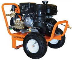
Commercial and Industrial
Cold Water Gas

Cold Water Gas • Rev. 12/05/2017
Easy-Kleen Pressure Systems
1-800-315-5533
This manual contains operational information that is specific for
commercial and industrial cold water, gas driven machines.
Read the following instructions carefully before attempting to assemble,
install, operate or service this pressure washer. Failure to comply with these
instructions could result in personal injury and/or property damage.
Table of Contents
IMPORTANT SAFETY INFORMATION .................................................................................................. 3
SPECIFICATIONS ....................................................................................................................................... 5
INTRODUCTION ........................................................................................................................................ 6
OPERATING INSTRUCTIONS .................................................................................................................. 7
CHEMICAL APPLICATION..................................................................................................................... 9
WINTER PUMP PROTECTION ............................................................................................................... 9
GENERAL MAINTENANCE .................................................................................................................... 10
MAINTENANCE CHECKLIST ................................................................................................................ 10
GLOSSARY OF TERMS ........................................................................................................................... 12
COMPONENT IDENTIFICATION ........................................................................................................... 13
QUICK DIAGNOSTICS AND SOLUTIONS GUIDE .............................................................................. 17
MANUFACTURER’S WARRANTY ........................................................................................................ 18
SERVICE MANUAL ................................................................................................................................. 11
3
Cold Water Gas • Rev. 12/05/ 2017
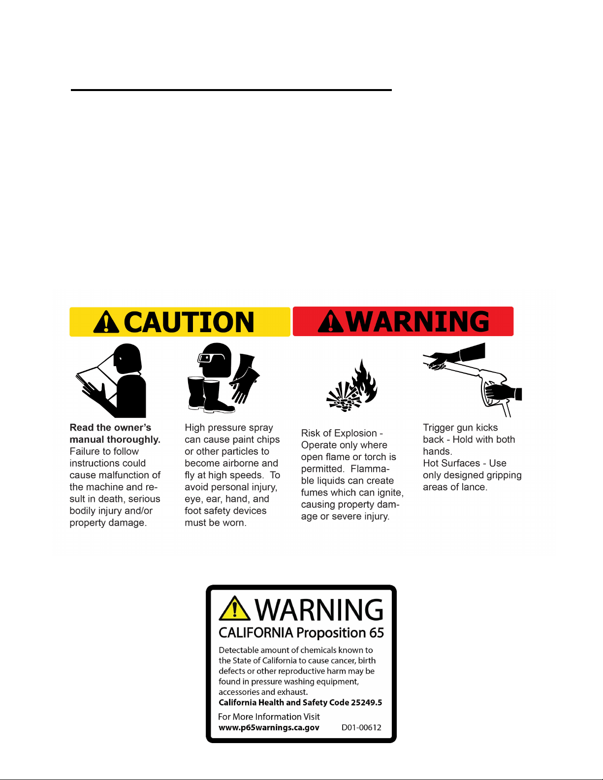
IMPORTANT SAFETY INFORMATION
Easy Kleen's first priority is the safe operation of our high pressure cleaning equipment. This
can be achieved by following the operation and maintenance instructions as explained in this
manual and all other enclosed information.
This manual contains essential information regarding the safety hazards, operation, and
maintenance associated with this machine. The manual should always remain with the machine,
including if it is resold.
ALL CAUTIONS AND SAFETY WARNINGS MUST BE FOLLOWED TO AVOID
INJURY OR DAMAGE TO EQUIPMENT.
THIS EQUIPMENT IS TO BE USED ONLY BY TRAINED OPERATORS AND MUST
ALWAYS BE ATTENDED DURING OPERATION.
If you need further explanation of any of the information in this manual, suspend any activity
involving the equipment and call our toll free number for assistance, 1-800-315-5533.
Cold Water Gas • Rev. 12/05/2017
4
5
Cold Water Gas • Rev. 12/05/2017
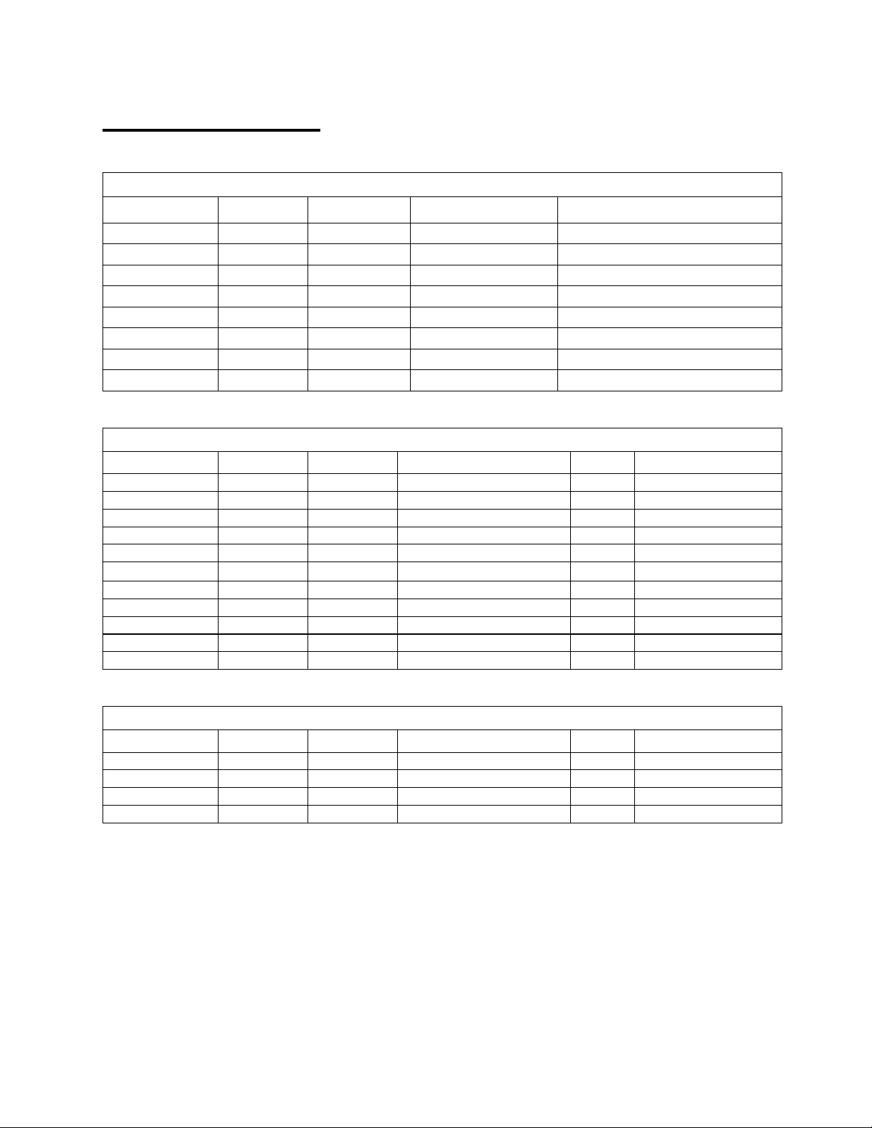
SPECIFICATIONS
Commercial Cold Water Gasoline
MODEL
GPM
PSI
HP/ENGINE
DRIVE
AS327GL
3
2700
6.5 LIFAN
DIRECT
AS327GK
3
2700
6.5 KOHLER
DIRECT
AS327GH
3
2700
6.5 HONDA
DIRECT
AS440GL
3.5
4000
15 LIFAN
DIRECT
AS440GK
3.5
4000
14 KOHLER
DIRECT
AS440GH
3.5
4000
13 HONDA
DIRECT
AS440GHGP
4
4000
13 HONDA
DIRECT
AS440GKGP
4
4000
14 KOHLER
DIRECT
Industrial Cold Water Gasoline
MODEL
GPM
PSI
DRIVE
HP
ENGINE
IS3504G-K
4
3500
GEAR BOX
14
KOHLER
IS3504G-H
4
3000
GEAR BOX
13
HONDA
IS3506G
6
3500
GEAR BOX
24
KOHLER
IS3607G
7
3600
BELT
25
KOHLER
IS3508G
8
3500
BELT
25
KOHLER
IS3675G-JB
7.5
3600
GEAR BOX JABSCO PUMP
25
KOHLER
IS2512G
12
2500
BELT
38
KOHLER
IS3010G
10
3000
BELT
38
KOHLER
IS5005G
5
5000
BELT
25
KOHLER
IS6045G
4.5
6000
BELT
25
KOHLER
IS7040G
4
7000
BELT
25
KOHLER
Industrial Cold Water Diesel
MODEL
GPM
PSI
DRIVE
HP
ENGINE
IS3204D
4
3200
BELT
9.8
KOHLER
IS5005D
5
5000
BELT
26
KOHLER
IS7004D
4
7000
BELT
26
KOHLER
IS8008D
8
8000
GEARBOX
58
KUBOTA
6
Cold Water Gas • Rev. 12/05/2017
INTRODUCTION
Thank you for selecting a quality Easy-Kleen product. We are pleased to have you included
among the many satisfied owners of Easy-Kleen cleaning machines. Years of engineering
have gone into the development of these fine products and only top quality components and
materials are used throughout. Each machine is carefully tested and inspected before leaving our
plant to ensure years of dependable performance.
To continue to receive satisfactory performance, remembering that this machine represents a
substantial investment on your part, and if properly cared for and maintained it will return this
investment many times over. As with all mechanical equipment, your machine requires proper
operation and maintenance as outlined in this manual for maximum trouble free life.
This manual has been prepared under the direction of our engineering and service technicians.
Their experience in designing, manufacturing, installing and servicing our equipment from our
company’s inception is condensed in this manual. They know what information the end user
needs in order to get the optimum performance from their pressure washer. Please read
carefully.
This manual contains information that will be specific for your pressure washer, as well as
similar models.
Carefully review any additional manuals that have been included with your system and
follow ALL ADDITIONAL OPERATING INSTRUCTIONS AND SAFETY NOTICES.
They are specific for the quality components that have been used to manufacture your
machine and are an integral part of the operating and maintenance procedures.
Easy-Kleen is proud of the equipment that we design and manufacture and we thank you for
making us your # 1 choice in pressure washers. If you have any questions please do not hesitate
to call us at 1-800-315-5533.
Our goal is that you will be satisfied with the performance, quality, and service you receive
from Easy Kleen, now and in the future.
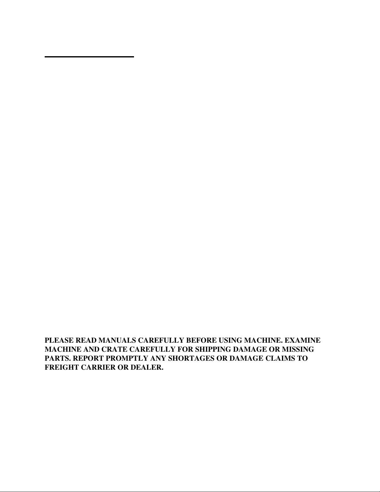
PLEASE READ MANUALS CAREFULLY BEFORE USING MACHINE. EXAMINE
MACHINE AND CRATE CAREFULLY FOR SHIPPING DAMAGE OR MISSING
PARTS. REPORT PROMPTLY ANY SHORTAGES OR DAMAGE CLAIMS TO
FREIGHT CARRIER OR DEALER.

7
Cold Water Gas • Rev. 12/05/2017
OPERATING INSTRUCTIONS
1. Perform pre-start maintenance inspection on all applicable systems prior to operating the
machine. This is essential for safe, effective and efficient operation. You will get optimum
performance from your system ONLY if these instructions and inspections are followed. Any
indication that the pressure washing system was not operated and maintained according to these
instructions may result in voiding the manufacturers’ warranty.
Location – These machines are gasoline powered and must be used outside in a well ventilated
area.
Controls – Make sure all controls are turned to the off position.
Pump – Oil Level - Ensure that the pressure washer is on a level surface. Check oil level on dip
stick. If the level is low, add the correct oil to the proper level. USE ONLY SAE 30 W NON-
DETERGENT OIL OR HYDRAULIC 68. DO NOT OVER FILL.
Gas Engine - Gasoline Level – The engine is a 4 cycle and uses regular octane, unleaded fuel.
DO NOT USE MIXED FUEL. Refer to the engine operation manual included with your
pressure-washing unit.
Gas engine - oil level – The engine is a 4 cycle and uses 10W30 detergent oil. Refer to Glossary
or engine manual.
Diesel engine – Refer to engine operation manual included with your high pressure cleaning
equipment for oil and fuel recommendations.
Visually inspect all electrical components to assure they are in good condition, showing No
signs of exposure, breakage or splicing.
Visually inspect all hoses, nozzles and guns to assure they are in good condition. If
replacements are necessary they must be rated to withstand the machine’s operating
pressure.
2. Attach high-pressure hose to water outlet quick coupler Attach the other end of high pressure
hose (with quick coupler) to gun and wand assembly. Ensure that coupler connections are tightly
locked together. Apply a sharp pull on hose to confirm they are secured.
Attach wand nozzle specific to task requirements (i.e. chemical or high pressure).
[Quick Coupling Operation – Pull back sleeve end and insert male end into nozzle quick coupler,
release sleeve and confirm connection by pulling on nozzle].
3. Attach water source to water inlet located on pump. The water source must be attached with a
good quality standard garden type hose (1/2” minimum is required). Connect male fitting into
water inlet on pump. Make sure that the inlet screen/filter is intact and fitted correctly. Turn on
water source. WATER MUST BE IN SUFFICIENT SUPPLY, AND PRESSURE MUST BE
BETWEEN 20 –60 PSI TO ENSURE PROPER AND SAFE OPERATION. Specific attention
should be given if using a well water supply. Ensure water is flowing from end nozzle with
trigger gun pulled. Deplete system of all air.
**Quick Coupler Operation – Pull back sleeve end and insert male end into nozzle quick
coupler, release sleeve and confirm connection by pulling on nozzle.

8
Cold Water Gas • Rev. 12/05/2017
4. Start gas/diesel engine
Refer to instructions in engine manual. You may need to hold wand trigger open while starting
engine in order to let it turn over more easily. MAKE SURE THAT THE ENGINE
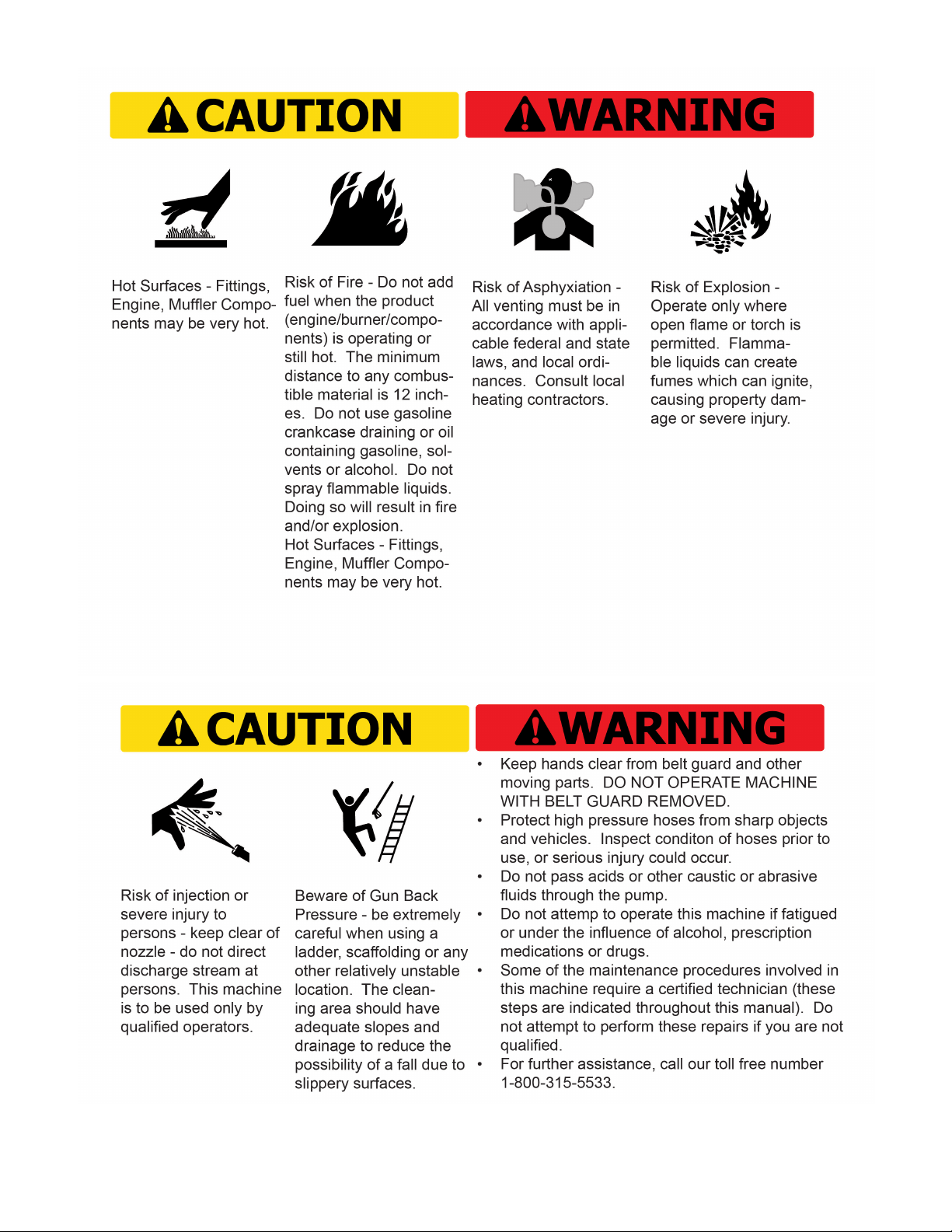
EXHAUST IS NOT FACING ANY FLAMMABLE MATERIALS.
4. Pressure adjustment - The pressure regulator (unloader) is located on the pump (see diagram).
It controls the pressure being generated by the pressure washer. This regulator may be adjusted to
desired pressure by turning the adjustment knob. Turning the adjustment knob clockwise will
increase pressure. NEVER OPERATE SYSTEM AT A HIGHER PSI THAN THE
MAXIMUM RATING. This machine has been adjusted to operate at a specific maximum
pressure as per the machine specifications. Pressure may be reduced for lighter use by turning the
unloader counter clockwise. If continuing to turn the unloader clockwise does not increase the
pressure, then this implies the maximum has been reached for the system. Any further turning of
the unloader will cause the pressure to spike when the wand trigger is released, resulting in
possible damage to the machine. To avoid this effect, loosen the unloader (counter-clockwise)
until the pressure just starts to drop (see pump head pressure gauge) and until it no longer exceeds
the maximum pressure rating for the machine.
5. You are now ready to start the cleaning operation - Pull trigger on the gun and wand
assembly to start cleaning. To stop pressurized water, release trigger. DO NOT LEAVE UNIT
RUNNING WHEN NOT IN USE. If left running, water will continuously be forced through the
bypass hose and back into the pump, which will cause the pump to overheat.
6. To stop operation. Turn off engine. Squeeze and release wand trigger after shutting off to
relieve system of pressure.
7. Prior to storage – Inspect pressure washer for any damage or required maintenance. If your
machine is to be exposed to cold weather, please refer to winter pump instructions found in this
manual. If possible, do not allow unit to remain outside in the elements.
**Warning – If unit is left running while not in use, pump damage may occur. Do not leave unit
running while not in use!

9
Cold Water Gas • Rev. 12/05/2017
CHEMICAL APPLICATION
Downstream Chemical Injection: Standard on direct drive units, optional on others. High
Pressure Soap is an optional feature.
NOTE: Do not remove back flow preventer as chemical may flow back into potable water
source. For standard chemical injection, ensure the black nozzle is properly fitted at the
end of the wand. The chemical injector will not function if this nozzle is not fitted.
1. Chemical preparation – Select detergent/chemical that best suits your cleaning task. Prepare
dilution according to the manufacturer’s instructions. The volume of chemical being used may be
adjusted at valve located on the chemical injector. Note: for EK Pumps, the volume is preset and
cannot be adjusted.
2. Insert the intake hose, located on the chemical injector at the pump, into the chemical being
used.
3. Fit black nozzle on the standard wand, or for the dual wand, turn adjustment knob on, and
adjust for required flow rate. For high pressure soap systems, the black nozzle is not needed; use
one of the other wand nozzles.
4. To apply chemical, engage trigger on pressure wand assembly. Turn chemical injector’s nipple
to adjust flow. For the high pressure soap systems, open ball valve and engage trigger.
5. Chemical can now be applied through pressure wand assembly. It will take 5 – 15 seconds for
chemical to travel to spray nozzle. The volume of chemical being used may be adjusted at the
chemical injector.
6. For best results apply chemical from bottom to top, and allow for proper penetration time prior
to rinsing. Do not allow chemical to dry. Rinse from bottom to top and then top to bottom.
WINTER PUMP PROTECTION
The following procedure MUST be used when the pressure washing unit is stored at
temperatures below freezing.
1. All water must be drained or blown (via compressed air) from system. Connect a short piece
of male fitted ½” garden type hose on to the water inlet on the pump assembly.
2. Place the open end of the hose into a wide mouthed container of full strength, winter rated,
vehicle windshield washing fluid or Anti-Freeze, RATED FOR MINIMUM -40°C.
3. Connect the pressure wand assembly.

10
Cold Water Gas • Rev. 12/05/2017
4. Start the pump and engage trigger on the pressure gun. Operate the system until the fluid runs
the same color as the windshield washing fluid. Your machine is now prepared for storage.
5. Disconnect fluid supply, blow out with compressed air, and cap end.
GENERAL MAINTENANCE
Water Condition
Use a softener on your water system if local water is known to be high in mineral content. The
advantages of soft water are very beneficial: prevents scale buildup in heater coil, cleans better
with considerably less detergent, and prevents streaking on painted surfaces and glass when
rinsing.
MAINTENANCE CHECKLIST
Maintenance for Pump
Daily:
1. Check oil for proper level and adjust accordingly.
2. Examine the quality of the oil.
3. Check pump for oil and/or water leaks.
4. Inspect and clean inlet filters.
Weekly:
1. Examine all fittings, components, hoses, connections, and nozzles for damages, loose
parts, or leaks. – Replace accordingly—
Recommendation for Oil Changes and Component Replacement:
1. Change the oil in the pump after the first 50 hours and every 500 hours after the initial
oil change. Use SAE 30 W Non-Detergent for GP Pumps and Hydraulic 68 for EK
Pumps.
2. Change all other components on the pump as needed.

11
Cold Water Gas • Rev. 12/05/2017
Maintenance for Gasoline Engine
Daily:
1. Check oil for proper level and adjust accordingly.
2. Examine the quality of the oil
3. Examine the air cleaner element
Weekly:
1. Examine engine components for damages, loose parts, or leaks.
Recommended Schedule for Oil Changes and Component Replacements:
1. Change engine oil after first 5 hours and every 100 hours after the initial oil change.
Use 10w-30 engine oil.
2. Replace Spark Plug every 100 hours.
3. Change air cleaner element every 100 hours.
4. Check fuel filters every 300 hours.
5. Change all other components on engine as needed.
This manual is intended for technical personnel to assist in the diagnosis and repair of issues
with pressure washers.
This manual is not intended for use by non-technical personnel.
It is advised to always refer to competent technical personnel when repairs are advised to
avoid equipment damage or potential personnel injury.
If you have any technical questions please do not hesitate to call us at 1- 800-315-5533.
Easy-Kleen Pressure Washers Service Manual

12
Cold Water Gas • Rev. 12/05/2017
GLOSSARY OF TERMS
PSI – Pounds per square inch. Pressure washers are designed and rated to operate at a specific
PSI. Operating at pressures exceeding the maximum rating could result in damage to the unit
and/or SEVERE PERSONAL INJURY.
GPM – Gallons per minute. The orifice on the pressure wand assembly has been selected to
deliver up to the maximum GPM for your machine.
PRESSURE WAND ASSEMBLY – This refers to the gun, wand, and nozzle.
PUMP – The pump moves the water through the system and delivers it to the pressure wand
assembly.
UNLOADER VALVE – Is a valve located at the head of the pump for unloading water back
into the bypass when the trigger gun is shut off. It also reduces the load on pump when gun is
off.
OIL, PUMP – The oil used within the pump to lubricate its operation. It is important to use only
SAE 30 W Non Detergent (for GP Pumps) or Hydraulic 68 (for EK Pumps) in the pump.
OIL, GASOLINE ENGINE – Gasoline Engines need appropriate lubricant. Use 10W30
detergent oil.
BACK FLOW PREVENTER – Device to prevent flow backwards into potable water supply.
MAXIMUM WORKING PRESSURE - Each machine is equipped with a safety pressure relief
valve which prevents over pressurization of the high pressure system. It is an important safety
device and must not be tampered with in any way.
PRESSURE SWITCH - A pressure switch is used to control the motor for the auto stop/start
feature (see diagram).
FLOW SWITCH – A flow switch is installed on the outlet of the water pump in auto stop/start
models and will shut off the pump and motor in the absence of water flow as well as turning it
back on when flow is detected (by squeezing the trigger).
13
Cold Water Gas • Rev. 12/05/2017
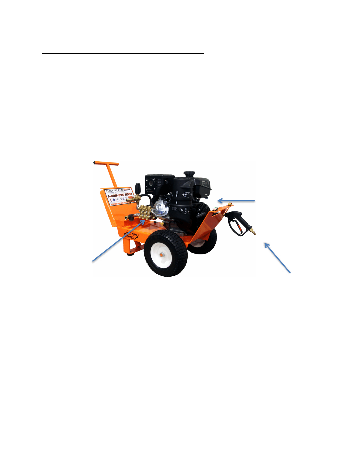
COMPONENT IDENTIFICATION
Commercial Model:
Water Pump
Engine
Wand and
Nozzles
14
Cold Water Gas • Rev. 12/05/2017
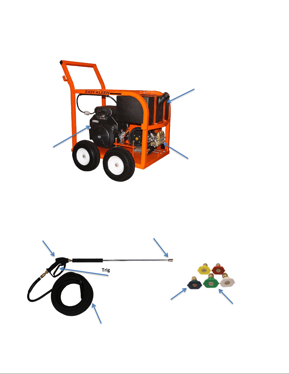
Industrial Model:
Pressure Wand Assembly:
Nozzle Quick
Coupler
Spray Gun
High Pressure Hose
Trigger
Wand
Nozzles
Black Nozzle for
Downstream Chemical
Application
10 Gallon Poly Fuel
Tank for Engine
Engine
Water Pump
15
Cold Water Gas • Rev.12/05/2017
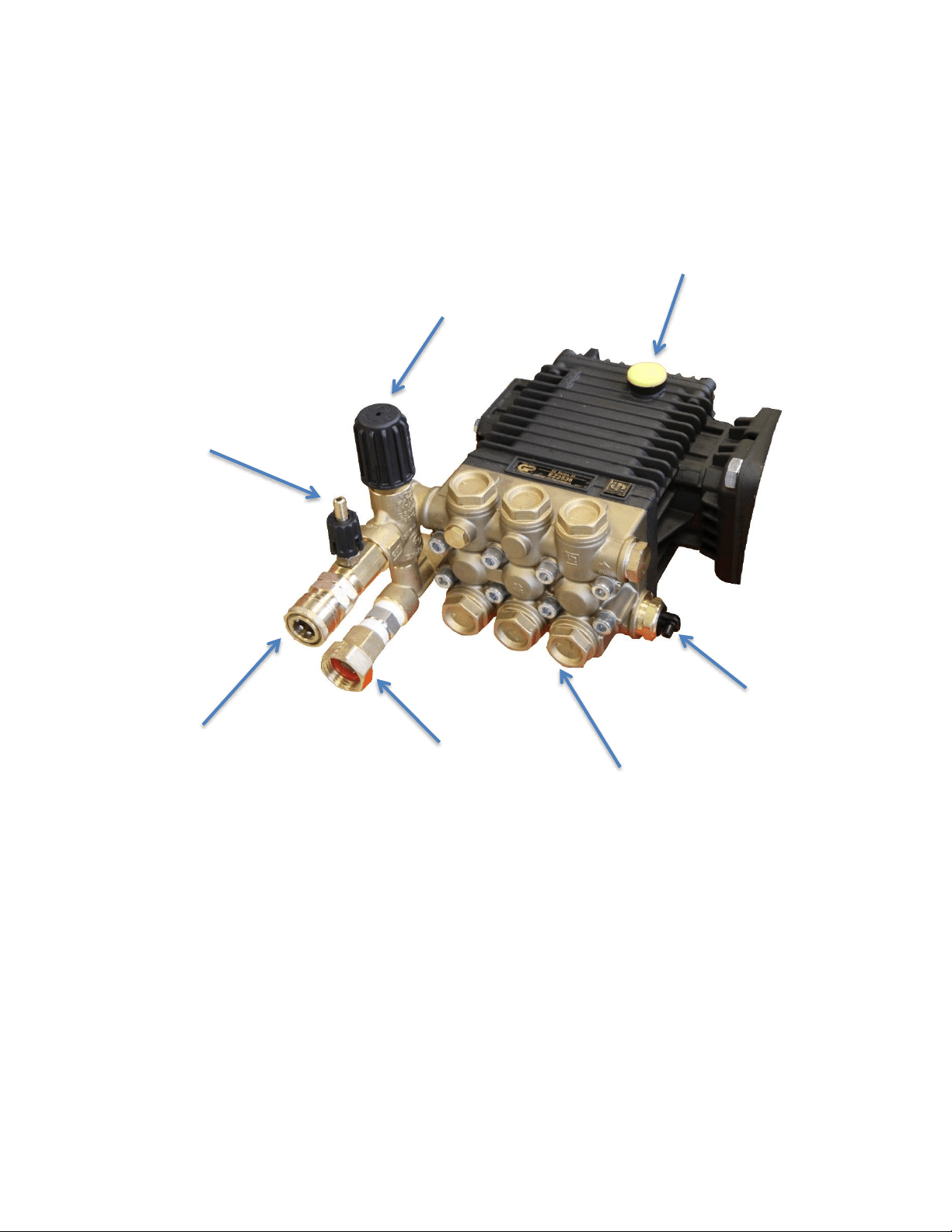
Commercial Model Pump Assembly:
Water Inlet
Water Outlet Quick
Connector
Water Pump
Chemical Injector
(Downstream)
Unloader
Oil Dipstick
Thermal Relief
Valve
16
Cold Water Gas • Rev. 12/05/2017
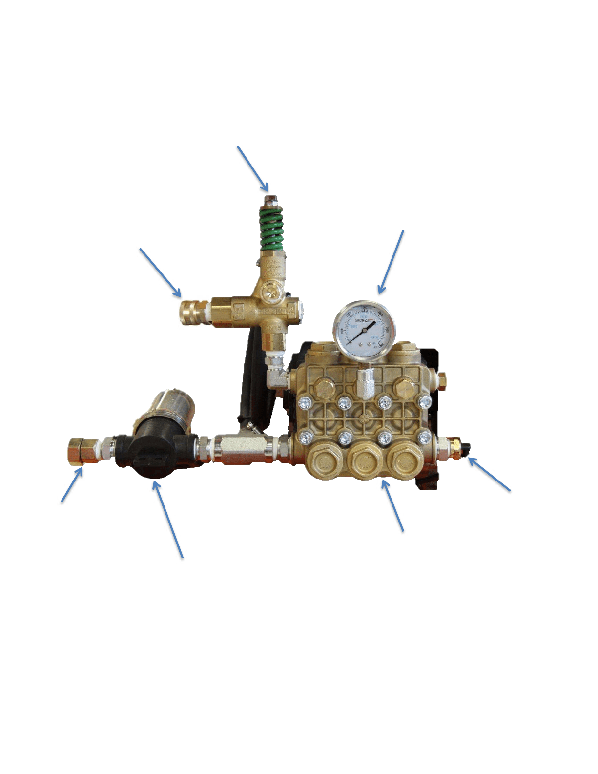
Industrial Model Pump Assembly:
Water Inlet
Water Filter
Pump Head
Pressure Gauge
Unloader
Water Pump
Water Outlet
Quick Connector
Thermal Relief
Valve
17
Cold Water Gas • Rev. 12/05/2017
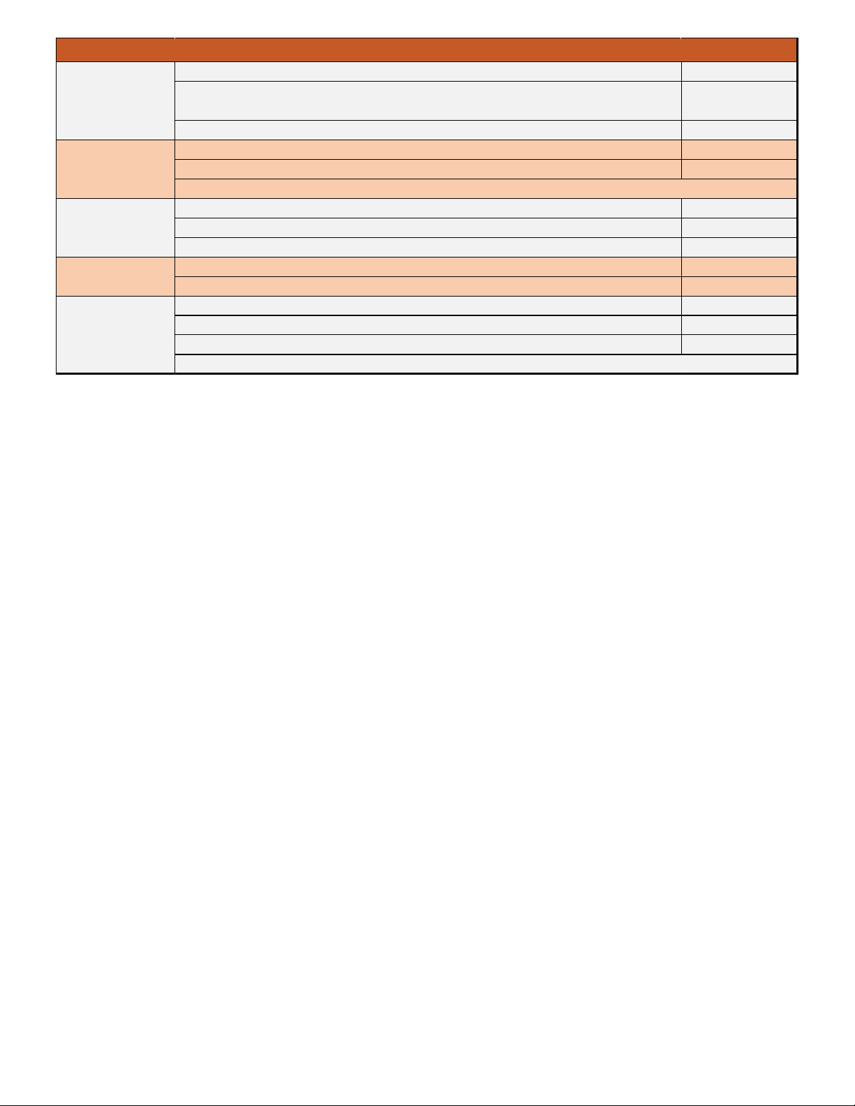
QUICK DIAGNOSTICS AND SOLUTIONS GUIDE
PUMP
TYPE OF OIL
EK Pump
Hydraulic 68 (650ml)
GP Pump
30W SAE Non-Detergent
PROBLEM
POSSIBLE CAUSES
SOLUTIONS
PRESSURE
No pressure
or
Very low pressure
Metal in oil
- Examine oil in pump to see if there is metal in oil.
- If you find traces or pieces of metal, your pump
has damaged components.
Dirt in water
- Verify if there is dirt in nozzle tip or in valves in pump.
- If nozzle is plugged, clean or replace it.
- If valves in pump are clogged, clean valves.
- If valves in pump are damaged, replace valves.
Wrong nozzle size
- Make sure you have the right nozzle size. The black
nozzle will drop pressure in order to use chemical injector
and is only for soap or chemical. If you are not using soap,
use a different color.
Pressure too high
Wrong nozzle size
- Make sure you have the right nozzle size.
Unloader adjusted improperly
or damaged
- Check pressure of pump with a pressure gauge and adjust
to desired pressure.
- If you cannot reduce pressure, replace unloader.
MANUFACTURER’S WARRANTY
AUG 1
ST
,
2019
Thank you for your purchase of an Easy-Kleen pressure cleaning system. All original
equipment are warrantied for a specific period and on the conditions set forth, that the
product is free from defect in materials and workmanship as follows:
Electric Motors
1Phase
18 Months
3 Phase
24 Months
For warranty for these items manufacturer needs to be contacted
Oil Burners
Igniters, Fuel Solenoid, Burner Motor, Fuel Assembly, Drive Shaft, Electrodes Blower, Wheel
Fuel Pump
1Year Parts
Propane / Natural
Gas Burners
Burner Rings, Gas Valves, Gas Valve Control Board
1Year
Fitting
All Fittings, Brass Stainless Steel, Steel, Etc.
30 Days
Heating Coils
All Coils
1Year Replacement
Under 5100 PSI- 5 Year Prorated
25% Year each year for 4
Years
Gas Motors
Honda and Kohler have manufacturer’s warranty. Manufacturer does not cover fuel systems.
Lifan Motor
Contact Easy-Kleen for Warranty
1Year (for commercial use)
Frames
Limited warranty on Frames, Belt Guard, Welds due to manufacture defect.
Paint is not covered under the manufacturer’s warranty due to the aggressive environment or natural wear.
Plastic Tanks
Water or Fuel
1Year
Accessories/ Wear
Items
Unloader, Regulating Valves, Safety Valves, Jetter Valves, Check Valves, Foot Valves,
Pulsation Dampeners, Trigger Guns, Rotary Nozzles, Chemical Injectors, Hose, Hose Reels,
Sandblast Kits, Surface Cleaner, Water Broom, Water Strainer, Belts, Ball Valves, Swivels,
Balanced Relief Valves, Accumulator Lances
90 Days
Electrical
Components
Switches, Time Over Loads, Contactors, Transformer, Thermostat, Vacuum Switches, Flow
and Pressure Switches, Relays, Primary Controls
90 Days
No Warranty Items
Fuel Filters, Nozzles, O- Rings, Thermo Relief Valves (Pump Seals, Valves, Plungers)
ANY PARTS NOT LISTED ABOVE CALL FOR WARRANTY TIME FRAMES
NOTE* Due to original equipment manufacturer’s requirements, Easy-Kleen is not permitted to perform warranty repairs or claims for electrical
motors, gas, or diesel engines. Please contact Easy-Kleen service department for a local warranty representative.
LIMITATIONS OF LIABILITY
Easy-Kleen liability for special, incidental, or consequential damages is expressly disclaimed. In no event shall Easy-Kleen’s liability exceed the
purchase price of the product in question. Easy-Kleen makes every effort to ensure that all illustrations and specifications are correct, however,
these do not imply a warranty that the product is merchantable or fit for a particular purpose, or that the product will actually conform to the
illustrations or specifications. Our obligation under this warranty is expressly limited at our option to the replacement or repair at our
manufacturer location, is such part or parts at inspection shall disclose to have been defective. Easy-Kleen does not authorize any other party,
to make any representation or promise on behalf of Easy-Kleen or to modify the terms, conditions, or limitations in any way. It is the buyer’s
responsibility to ensure that the installation and use of Easy-Kleen products conform to local codes. While Easy-Kleen attempts to ensure that
its products meet national codes, it cannot be responsible for how the customer chooses to use or install the product. THE WARRANTY
CONTAINED HEREIN IS IN LIEU OF ALL OTHER WARRANTIES, EXPRESSED OR IMPLIED, INCLUDING ANY IMPLIED WARRANTY OF
MERCANTABILITY OR FITNESS FOR A PARTICULAR PURPOSE ARE EXPRESSLY LIMITED TO THE DURATION OF THIS WRITTEN WARRANTY.
Easy-Kleen reserves the right to make any changes to an Easy-Kleen product at any time without incurring any obligation with respect to any
product previously, ordered, sold, or shipped.
PUMP WARRANTY TIME LINE
Cat Pumps
Direct Drive Pumps 2 Years
Car Wash Pumps (Including all models used in Car Wash or Portable Fresh Water Pressure Cleaning applications
5 Years
All other pumps not listed above 1 Year
Giant Pumps
Pressure Washer and Self- Serve Car Wash Applications 5 Years
All other Giant Pumps, Industrial and Consumer Pumps 1 Year
Lifetime on Manifolds due to Manufacture defects
AR Pumps
Plunger Pumps 5 Years
Axial Pumps 1 Year
AR Accessories 90 Days
General Pumps
Manifolds 5 Years
Pressure Washer Pumps 5 Years
EK Pumps
Manifolds 5 Years
Pumps 1 Year
Accessories 90 Days
Manufacturer does not cover wet end of Pump Seals, Valves, and Plungers.
WARRANTY REPAIRS
Warranty claims must first contact Easy-Kleen’s Service Department to be issued a preauthorized repair number (PARN). You will need a copy of
your invoice and the equipment serial number.
If new parts are needed, they will be invoiced to you as normal. Defective parts are to be sent to us PREPAID for warranty consideration. If a
part is found to be defective, a credit will be issued to cover the costs of parts. All work is be performed at the manufacturers’ place of business
when returned PREPAID. This warranty will not cover labor if warranty work is conducted at the customer’s place of business. Road service will
be charged at the normal rate in these situations.
WARRANTY DOES NOT COVER:
• When warranty part is warrantied the warranty time frame does not re-start.
• Warranty freight cost will be covered by Easy-Kleen for the first 30 days of sale of the machine due
to manufacture defect or workmanship.
• Neglect of the periodic maintenance as specified in the owner’s manual.
• Improper repair or maintenance.
• Operating methods other than those indicated in the owner‘s manual.
• The use of non-genuine Easy-Kleen parts or accessories other than those approved by Easy-Kleen
• Exposure of chemical agents, such as: Sea Water, Sea Breeze, Salt, or other environmental phenomenon.
• Collision, fuel contamination or deterioration, neglect, unauthorized alteration or misuse.
• Warranty does not cover travel or time if a service call is needed.
• Warranty does not apply when pump or accessory is altered or used in excess of recommended
speeds, pressure, temperatures, or handling fluids not suitable for pump or accessory material.
• Construction warranty does not apply to normal wear.
• Warranty does not apply to normal wear (such as but limited to seals, packing valves, plungers and
sealing O-Rings), freight damage, freezing damage or damage caused by parts or accessories not
supplied by Easy-Kleen.
• After 30 days freight will become chargeable.
• Warranty covers In-House Labour and Parts if manufacture defect is repaired at an Easy-Kleen approved Service Center.
WARRANTY DOES NOT COVER DEFECTS CAUSED BY:
• Improper or negligent operation or installation, accident, abuse, misuse, neglect, unauthorized modifications, including, but not
limited to, the failure of the customer to comply with recommended product maintenance schedules.
• Improper repairs
• Neglected maintenance/incorrect operation (specified in the Owner/Operator’s Manual
• Unapproved devices or attachments
• Water sediments, rust corrosion, thermal expansion, scale deposits or a contaminated water supply or use of chemicals not approved
or recommended by Easy-Kleen Pressure Systems Ltd.
• Improper voltage, sudden voltage spikes or power transients in the electrical supply
• Usage which is contrary to the intended purpose of the equipment
• Natural calamities or disasters including, but not limited to, floods, fires, wind, freezing*, earthquakes, tornados, hurricanes and
lightning strikes
*Includes damage done to components that come in contact with water as a result of freezing in a non-winterized machine.
service@easykleen.com 1-800-315-5533 www.easykleen.com
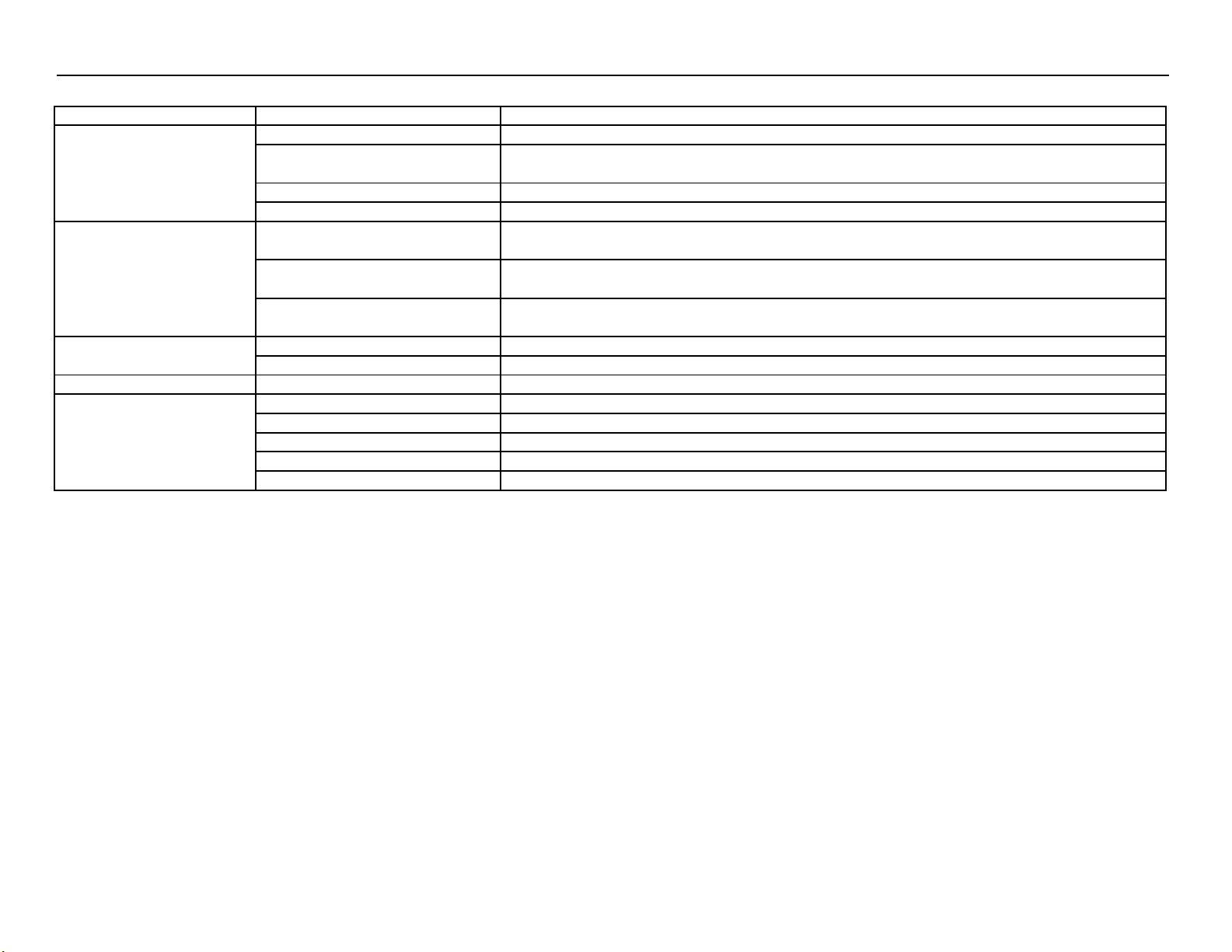
POWER SYSTEM DIAGNOSTICS - Gas Motor Not Starting
PROBLEM
POSSIBLE CAUSE
SOLUTION
Gas motor not starting
Fuel
Check to see if proper fuel levels are maintained
No ignition
Check ignition by removing spark plug from cylinder. If electric start, try starting using the recoil starter.
Electric Starter/Battery
Recharge or replace battery.
Fuse blown in key switch
18 amp engine, open key switch, replace 30 amp fuse
Spark Plug - strong gas
smell
Flooded
Wait 5 minutes before attempting to restart.
No ignition
Check ignition by removing spark plug from cylinder. If electric start, try starting using the recoil starter.
Bad plug
Check spark plug and replace if necessary. Carbon deposits can indicate a fouled plug or too much
fuel.
Plug does not fire
Poor connection
Inspect the ignition connection.
Bad magneto
Check the source of spark plug for engine ignition.
Bad ignition system
Poor connection
Check the source of spark for the engine ignition.
Spark Plug - no gas smell
No fuel to cylinder
Check fuel delivery from carburetor to cylinder. Check carburetor float bowl for fuel.
Fuel line restricted
Inspect fuel line to carburetor for restrictions or clogging. Flexible line may be kinked.
Stuck carburetor float
Unstick float
Clogged carburetor needle valve
Unclog needle valve.
Bad fuel pump
Replace fuel pump.
19
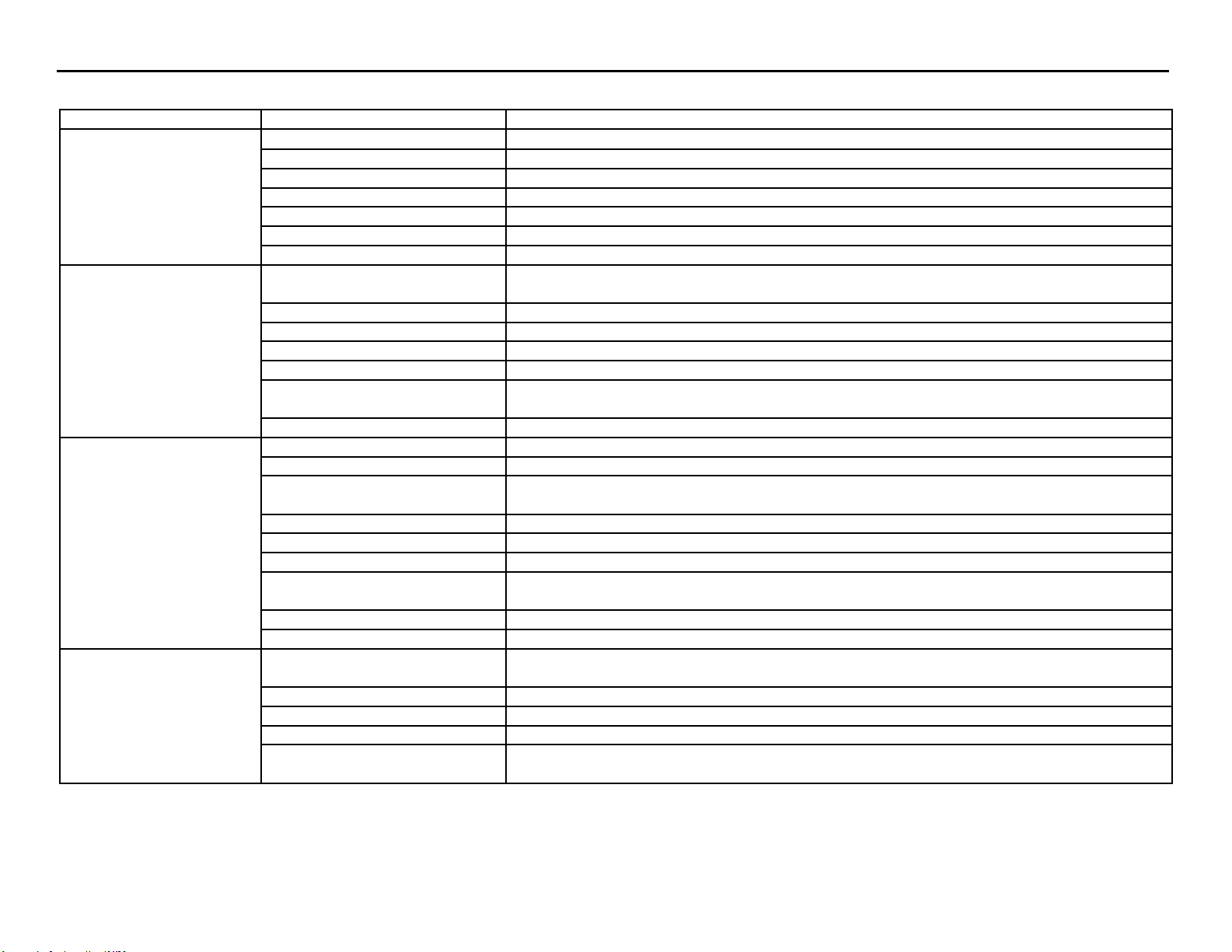
FLUID SYSTEM DIAGNOSTICS - Flow and Pressure
PROBLEM
POSSIBLE CAUSE
SOLUTION
No Flow
No power
Make sure pump is operating. Check drive belts and couplings, make necessary adjustments.
Trigger gun valve
Check trigger gun, repair or replace.
No water source
Ensure water supply is not restricted and hoses are in good repair and not kinked.
Clogged spray nozzle
Check spray nozzle, repair or replace.
Clogged inlet filter
Check inlet filter, repair or replace.
Float Valve stuck (optional)
Float valves can become stuck in the "UP" position. Manually dislodge and inspect for problems.
Faulty unloader valve
Remove and check for proper action, repair or replace.
Low pressure, adequate
flow
Incorrect or no spray nozzle
Nozzle should be properly sized for the system. Low pressure indicates that the nozzle in use is
too large.
Worn spray nozzle
Replace nozzle when it shows signs of internal erosion.
Debris in valves
Clean valves and check O-rings for pits and cracks.
Lance on low pressure
Adjust pressure so the water flows through properly.
Unloader is not adjusted correctly
Adjust unloader to proper level.
Pressure gauge inaccurate
Use a new pressure gauge on a quick connect at outlet to check system pressure and replace if
gauge is faulty.
Pump packings bad
If low pressure persists, pump packings may need replaced.
Low pressure, low flow
Volume Improperly adjusted
If unit has volume adjustment, it may need readjustment
Discharge leaks
Look for leaks on the discharge side of system.
Downstream chemical injector
(Dema)
Remove the injector and retest system. If the flow is restored, replace the injector.
Loose drive belts
If belts do not have proper deflection, replace them.
Pump not running at rated speed
Check engine throttle and see that the motor is rated for the same speed as the pump.
Stripped pump drive coupling
Inspect coupling and repair or replace.
Defective easy start valve
(optional)
Check the start or throttle-back valve for proper operation.
Malfunctioning motor or gear
Ensure that the motor or engine is working properly
Unloader stuck in bypass
Piston assembly may be stuck or fouled
Low pressure, low flow -
Bogs
Outlet restriction
Build up can restrict flow. If water is not flowing freely, flush with garden hose to isolate the clog
or restriction.
Clogged nozzle
Distorted spray pattern can indicate a clogged nozzle.
Nozzle too small
Ensure nozzle is proper size for the system.
Hose restriction
Correct any kinks or restrictions. Replace crushed hoses.
Debris in the system
Debris can lodge in the discharge side of the system (valves, fittings, injectors, filters) Flushing
with water may correct it.
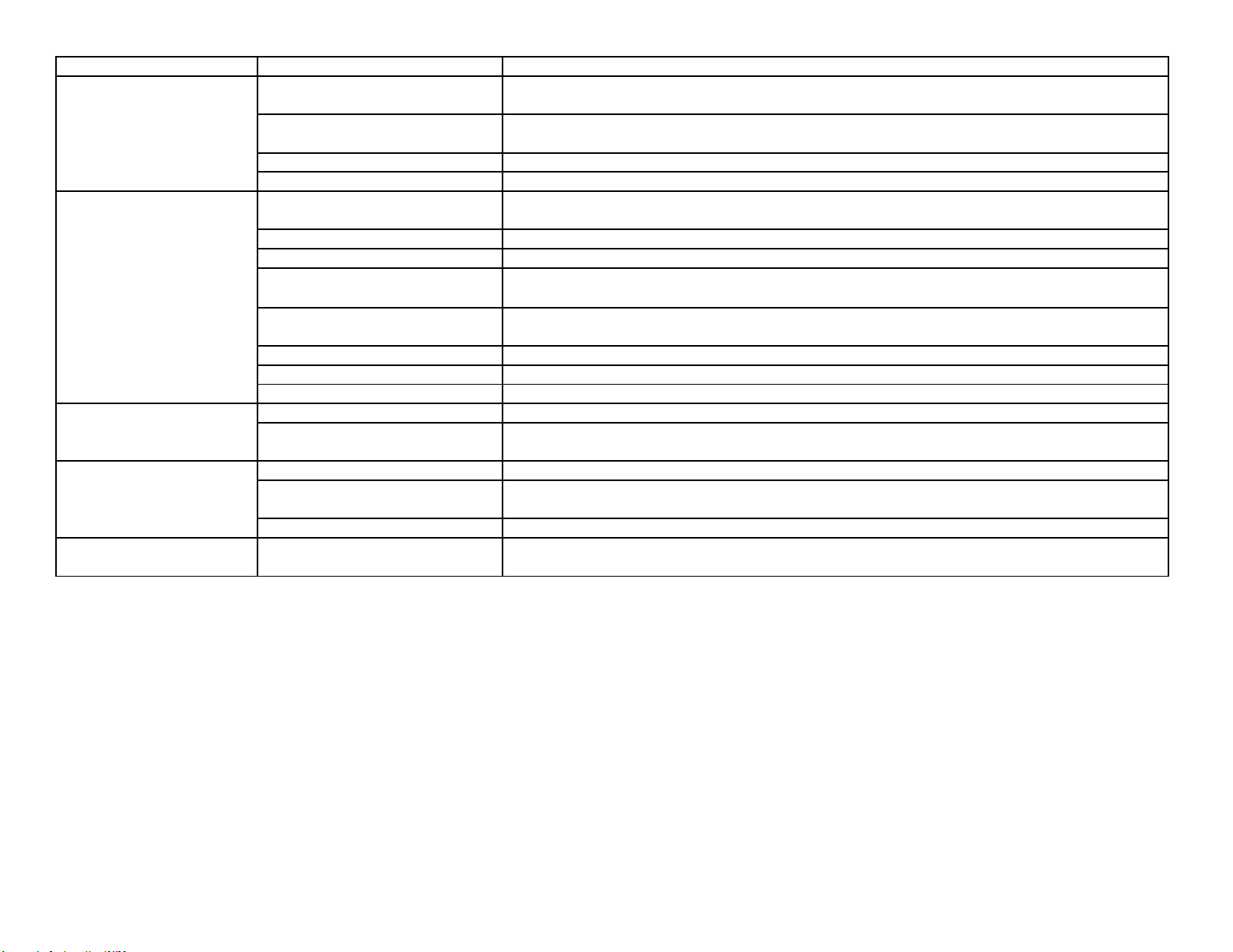
PROBLEM
POSSIBLE CAUSE
SOLUTION
Excessive pressure
Small spray nozzle
Nozzle must be properly sized for the rated flow and pressure. Reset unloader or pressure relief
if nozzle size is changed.
Faulty pressure gauge
Check the pressure gauge using a properly calibrated pressure gauge on quick connects at the
equipment outlet.
Improperly adjusted unloader
Adjust to the proper pressure using pressure gauge.
Faulty unloader
Check the unloader action. If it is not working properly, it may need repaired or replaced.
Pump chatters, cavitation,
vibration
Air in system
Inspect places where air can enter the system. i.e. fittings, hose, connections etc.
Chemical line not submerged
If the chemical valve is on, ensure that the chemical line is fully submerged in the chemical
Inlet line restricted
All inlet connections should be snug and not kinked to reduce the chances of pump starvation.
Inadequate water supply
Water supply to the system must meet or exceed the rated flow (GPM) on the serial number
plate. Faucet must be completely opened or water above the tank outlet in a gravity fed system.
Float valve stuck (optional)
If float valve is stuck in the up position, water can not enter the float tank. Unstick valve if
possible of replace if necessary.
Turbulence in float tank (optional)
Excessive turbulence allows the pump to draw air into the system. Correct excessive turbulence.
Inlet or inlet strainer clogged
Regularly clean the inlet and inlet strainer to keep debris from entering the float tank
Water supply too hot
Inlet temperature should not exceed 140F - 160F range.
Inlet line vibrates
Air in system
Inspect places where air can enter the system, i.e., fittings, hose, connections etc.
Debris in inlet check valves
If there is no float tank and the outlet line does not vibrate, the inlet check valve may be
clogged. Remove debris. Check O-rings under valves.
Outlet line vibrates
Air in system
Inspect places where air can enter the system, i.e., fittings, hose, connections etc.
Debris in inlet check valves
If there is no float tank and the outlet line does not vibrate, the inlet check valve may be
clogged. Remove debris.
Pump packing bad
If they show signs of ware or damage, replace them.
Inlet and outlet lines vibrate
Inlet and outlet check valves
fouled
Look for the source of debris in the inlet and discharge check valves and remove.
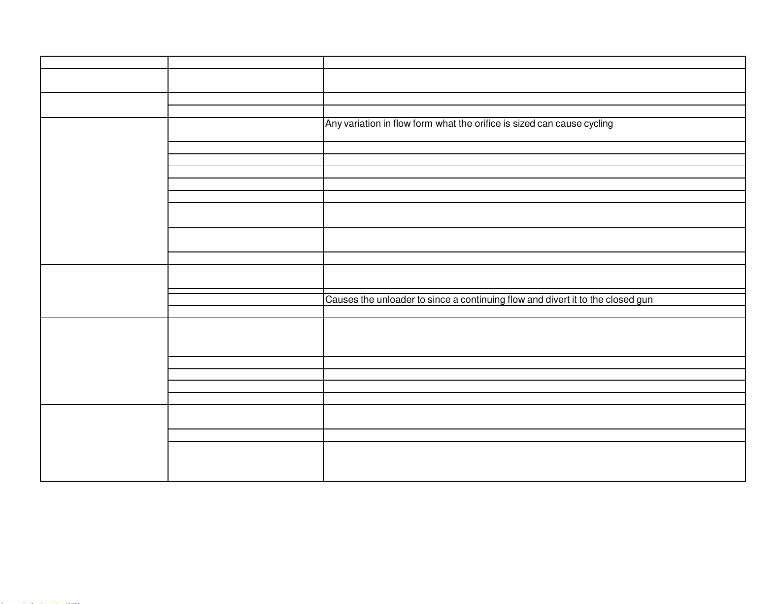
FLUID SYSTEM DIAGNOSTICS - Unloader
PROBLEM
POSSIBLE CAUSE
SOLUTION
Very low or no flow
Unloader stuck in bypass
Isolate the flow problem. If it occurs before the unloader discharge point, check the piston
assembly to see if it is fouled or stuck in bypass mode.
Unloader will not unload
Debris in unloader
Take bottom nut off unloader, identify ball, spring and seat. Clean out any debris and
Sever leak on the outlet of unit
Check for leaks and repair.
Unloader (flow) cycles with
system under pressure
Improper flow
Any variation in flow form what the orifice is sized can cause cycling. System must produce the
rated flow constantly.
Nozzle to small
A nozzle that is too small can cause the flow to be reduced.
Nozzle clogged
A distorted spray pattern indicates a clogged nozzle.
Improper unloader orifice
The systems rated output should indicate the proper sized orifice for your system.
Unloader orifice clogged
Check the orifice for clogs and clear out any debris.
Injector orifice clogged
If the system has a Venturi injector downstream of the unloader, check the orifice for clogs.
Other downstream restriction
Scale buildup can restrict flow. Check: controls, valves, switches, trigger gun, and lance.
De-scale as necessary and begin preventive maintenance program for scale prevention.
Pump not delivering the rated
pressure
See low pressure or low flow diagnostics.
High water supply pressure
Check inlet water supply for excessive pressure.
Unloader (flow) cycles with
system in bypass
No restrictions on the unloader
Check unloader bypass port to see if a flow restrictor is properly installed. Install one if none is
present.
Downstream leakage (excessive)
Causes the unloader to since a continuing flow and divert it to the closed gun. Repair or replace.
Accumulator downstream (option)
Remove the accumulator from the system.
Unloader (pressure)
produces smooth flow & low
volume
Unloader adjusted too low
Adjust the unloader using the pressure gauge for the correct pressure.
Spray nozzle clogged
A distorted spray pattern indicates a clogged nozzle.
Spray nozzle too small
A small nozzle causes a reduced flow and cycling may result.
Injector orifice blocked
If the system has a Venturi injector downstream of the unloader, check the orifice for clogs.
System not delivering rated flow
See flow diagnostics.
Unloader (flow) produces
smooth flow & low volume
Unloader adjusted too low
Adjust unloader and regulator until proper pressure is achieved.
Unloader valve stuck in bypass
If unloader is sticking, repair or replace as necessary.
Restriction in system
Downstream restrictions can cause a reduction in flow. Check; controls, valves, switches, trigger
gun, and lance. Descale as necessary and begin preventive maintenance program for scale
prevention.
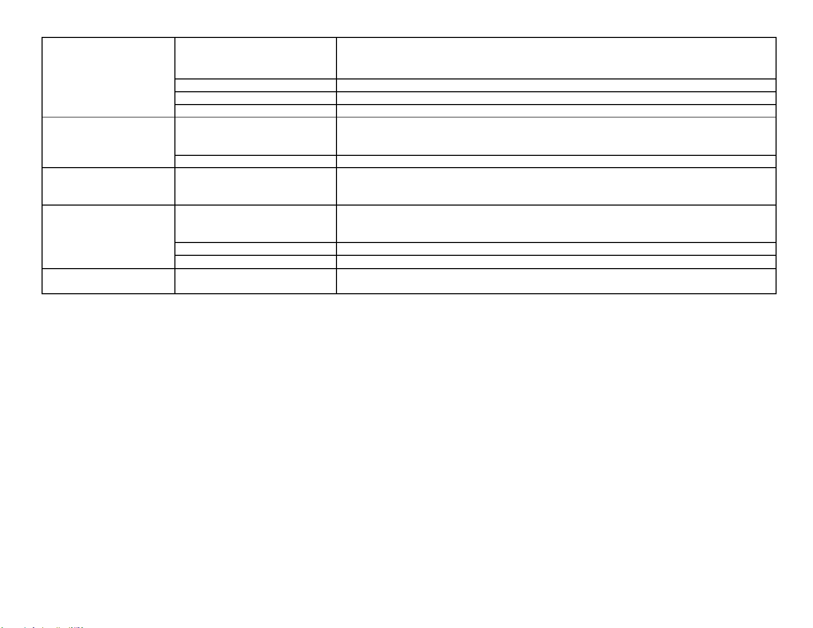
Unloader (pressure)
produces low flow and
normal pressure
Unloader adjusted too low
If the unloader is diverting flow to bypass it may be adjusted too low, readjust as necessary.
Spray nozzle too large
Ensure the proper nozzle is installed on system.
Internal nozzle erosion
The number of hours of usage can give you an idea to the extent of the ware. If in doubt, change
Insufficient pump pressure
Check pump seals and packings and tighten drive belts.
Unloader (flow) produces
low flow & normal pressure
Unloader adjusted too low
If unloader is diverting flow to bypass, readjust using the pressure gauge.
Nozzle too large
Ensure the proper sized nozzle is being used.
Unloader (pressure) leaks
from main spring or
adjusting bolt
Shaft O-ring in valve body warn
Check O-rings for ware or damage and replace as necessary.
Unloader (flow) pressure
increases when trigger
released
Unloader piston stuck or frozen
Check unloader shaft for proper action. Release piston and shaft or replace unloader.
Bypass port clogged or restricted
Ensure that unloader bypass port is not clogged
Excessive tension on main spring
If tension is incorrect, adjust or replace as necessary.
Unloader (flow) leaks water
around adjusting bolt
Sleeve O-ring worn
Check O-rings for ware or damage and replace as necessary.
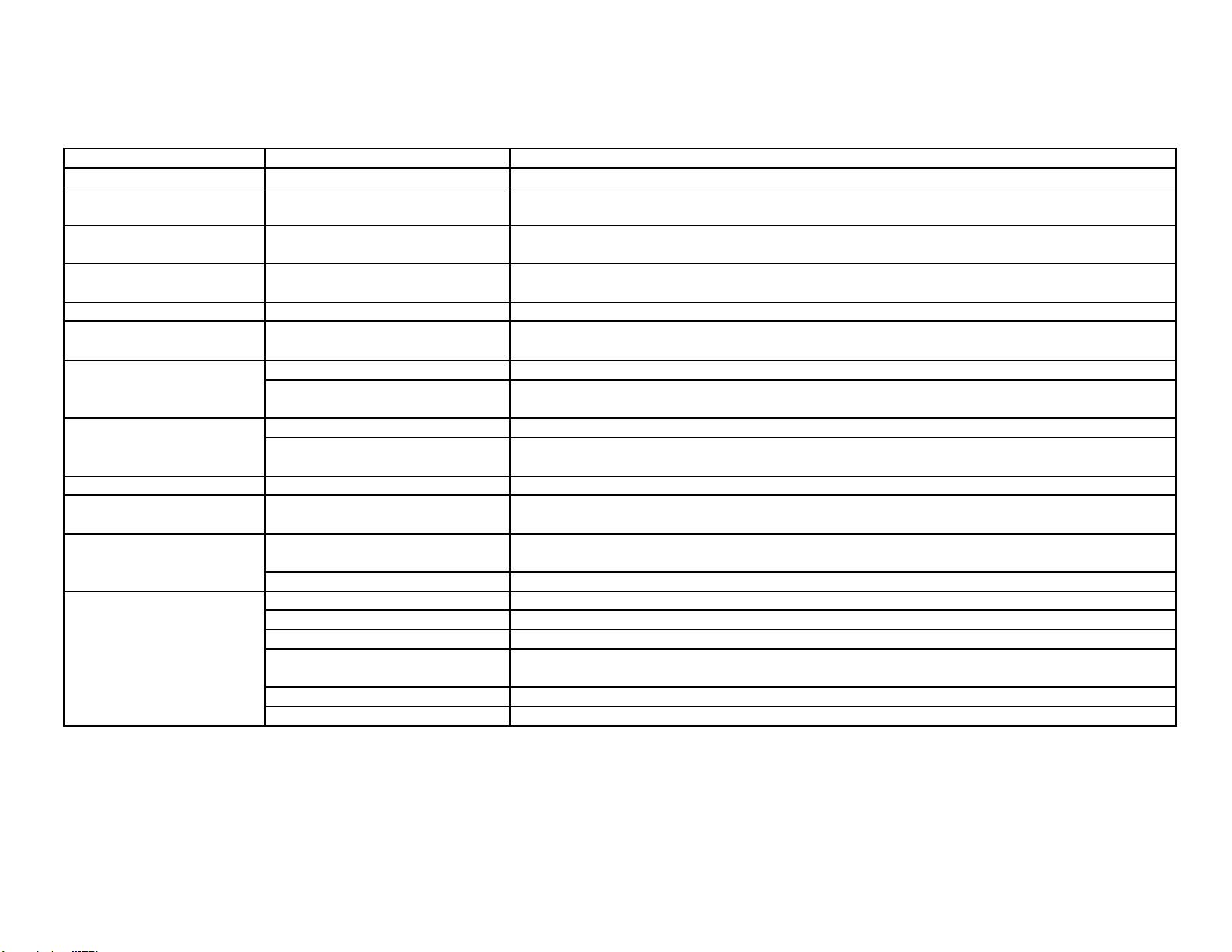
FLUID SYSTEM DIAGNOSTICS - Leaking
ANY LEAKS SHOULD BE REPAIRED ASAP TO PREVENT DAMAGE TO THE
SYSTEM.
PROBLEM
POSSIBLE CAUSE
SOLUTION
From inlet
Garden hose washer
Ensure the washer is present and in good condition.
From low pressure (inlet)
line fittings
Loose clamps or connections
Low pressure line should be properly sealed on barb and tightly clamped.
From float tank(option)
Float tank full of water or stuck
If float is not floating above water, check the float to see if it has filled up with water. If
necessary, drain and seal.
From pressure fittings
Fittings not tightened or taped, or
cracked
Usually metal to metal fittings should be taped with Teflon tape or lock tight to provide a tight seal.
From quick connects
Bad O-rings If quick connect O-ring shows wear or damage, replace it.
From pump
Bad packing
If the seal leak is detected under the pump manifold, packing may be worn and in need of
replacement.
From trigger gun
Bad rod O-ring If O-rings show wear or damage, they may need replaced.
Stripped connectors
Physical damage may not be apparent, but unseen warping from freezing or extreme pressure
can still cause leakage.
From nozzle
Weep gun (optional)
If a weep gun has been installed, check the gun valve seat to ensure it is functioning properly.
Damage gun valve ball or seat
Inspect trigger gun valve assembly for damage or ware to ball or seat. Lodged debris can stop
valve from closing. Repair with kit or replace.
From unloader
Bad O-rings or seals
If quick connect o-ring shows wear, damage or improper seating.
From variable pressure
Lance(option)
Bad O-rings at adjusting knob Inspect O-rings for ware or damage and replace as necessary.
Unloader will not unload
Debris in unloader
Take bottom nut off unloader, identify ball, spring and seat. Clean out any debris and
reassemble.
Sever leak on the outlet of unit
Check for leaks and repair.
From pressure relief valve
System over pressure
See pressure and flow diagnostics to find the cause of the excessive pressure and correct it.
Clogged nozzle
Spray pattern will be distorted if nozzle is clogged, clean out.
Trigger gun valve not working
If trigger gun valve action is not correct, repair or replace.
Excessive pressure spike
If water spurts from valve when trigger is released, check unloader adjustment. Pressure spike
should be below the level where pressure relief valve is activated.
Wear or damage to ball or seal
Inspect ball and seal for damage and adjust as necessary.
Improper relief valve adjustment
Adjust valve properly.
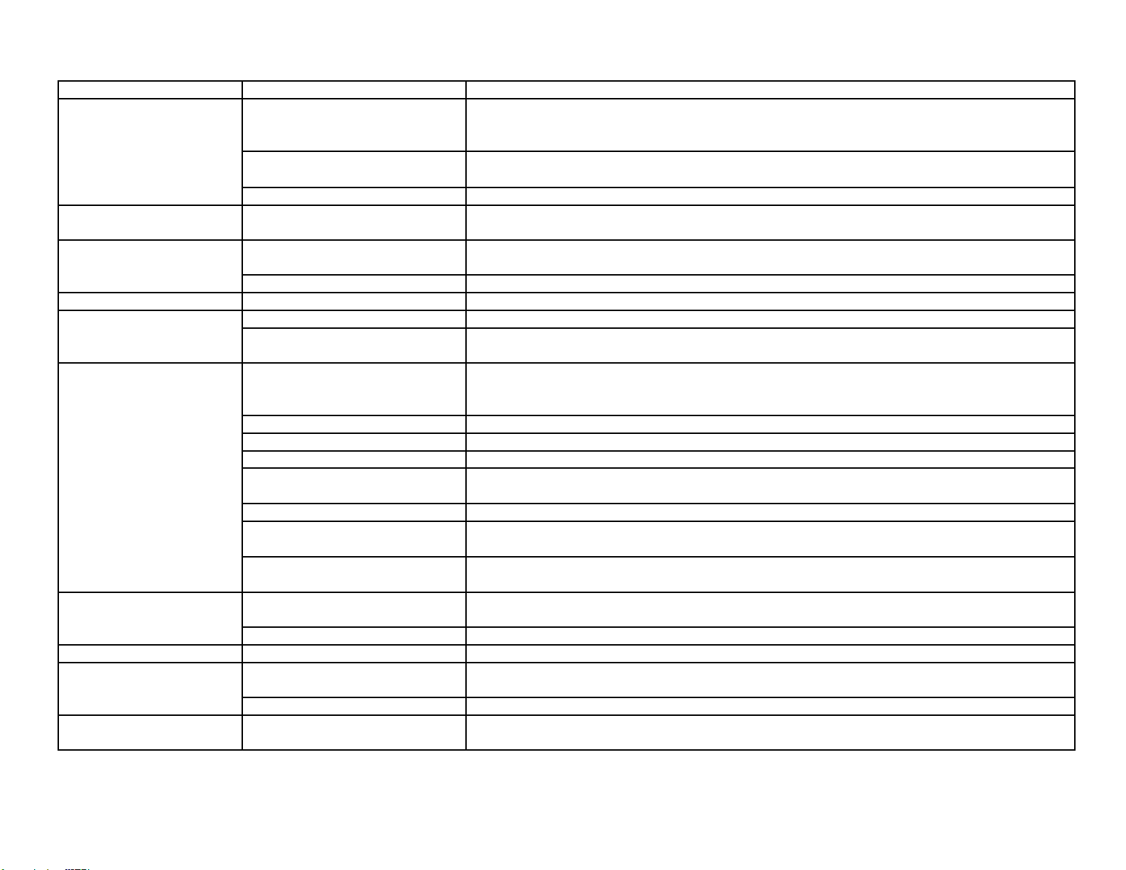
FLUID SYSTEM DIAGNOSTICS - Trigger Gun/Spray Nozzle
PROBLEM
POSSIBLE CAUSE
SOLUTION
No nozzle flow from nozzle
when trigger depressed.
Broken piston rod in trigger gun
If water flows through discharge hose without gun, check trigger gun valve piston rod and
replace if necessary.
Missing metal insert in trigger gun
(European style gun)
Inspect to assure insert is in place.
Blockage in system past gun
Check nozzle or spray accessory for blockage and clear it.
Excess pressure when
trigger gun is released
Excessive pressure spikes
After unloader increases pressure to a maximum, further adjustment will only increase the
pressure spikes. Re-adjust.
Flow not stopping when
trigger gun released
Broken return spring on trigger gun
If trigger action is too loose, return spring may need replaced.
Debris in gun valve
Debris in gun valve can stop piston return. Clear debris.
Trigger action sticks
Keeper plug too tight
It may be possible to loosen plug slightly without leakage but it will likely need replaced.
Trigger gun leaks
Worn or bad O-ring
Check trigger gun o-rings for ware or damage and replace.
Stripped or loose connections
Physical damage may not be apparent but unseen warping from freezing or sever over
pressure may still cause leaking.
No chemical
Chemical valve closed
Black nozzle
Open chemical valve. If It chatters with no chemical delivery, air is being drawn from the
upstream side of the pump. Check fittings, connections and ensure the inlet line is fully
submerged into the chemical jug.
Chemical dried up in the injector
Inspect and clean as necessary.
Chemical foot strainer clogged
May be a strainer or check valve. Ensure that the ball is not stuck or clogged.
Chemical line kinked
Chemical line kinking or binding prevents chemical delivery.
Chemical line too long
An overly long chemical line can prevent the pump from drawing chemical into the system. Try
installing a shorter line.
Chemical too dilute
Verify chemical strength.
No adjustment for low pressure
Downstream injectors only - Low pressure is required for most injectors to draw chemical. If no
adjuster exists it may need low pressure spray nozzle installed on the lance.
Incorrect injector orifice
If not properly sized for the systems rated output, chemical delivery problems will result. Check
serial plate for specs.
Excessive chemical
Valve improperly adjusted, check
knob on injector
To properly adjust, a chemical flow meter may be used to precisely measure chemical flow.
Chemical dilution to strong
Verify chemical strength.
Spray pattern irregular
Clogged nozzle
Spray pattern will be distorted if nozzle is clogged.
Volume proper, pressure
low
Nozzle too large
Ensure that the nozzle is sized properly sized for the system
Internal nozzle wear
A loss of pressure may result form gradual nozzle wear. Replace a nozzle of correct size.
Pressure proper, volume
low
Clogged nozzle
Spray pattern will be distorted if nozzle is clogged. Check nozzle for clogging if the unit has a
pressure unloader.
BOILER SYSTEM DIAGNOSTICS - Oil Burner Will Not Fire
PROBLEM
POSSIBLE CAUSE
SOLUTION
Not reaching rated pressure
flow
Not activating boiler controls
Correct the fluid problem first - See fluid systems diagnostics
Thermostat on low setting
Thermostat set too low
Set thermostat to an output temperature requiring heating.
No or low fuel in tank
Burner no getting adequate fuel
Check fuel and bring to proper levels. Inspect fuel tank for water or debris.
Low fuel shut-off control activated.
Full featured equipment may have a shut off if fuel is low.
No air movement through
stack
No air being supplied
Ensure that the blower is working and that the air band or damper is properly adjusted and in
good repair.
Thermal reset tripped
Press the thermal reset button on burner motor. If the reset trips again an additional problem
must be sought.
Burner motor or capacitor is bad
If motor does not turn, first check thermostat/press switch, the motor starting capacitor and
finally the burner motor itself.
Fuel in the fuel tank
Contaminated fuel in the tank
Ensure that the proper clean fuel is being used. If not, siphon any debris or water from the tank.
Improper fuel in the tank
If the improper fuel is found in the tank, drain and rinse the tank, then fill with proper fuel.
Low fuel shut-off sensor stuck or
faulty
Check the sensor. The assembly may need to be removed to un-stick the float or to replace it
completely.
Water in the fuel filter bowl
Water in fuel supply
Drain water from the tank promptly to prevent rusting. If fuel delivery problems persist, check the
fuel pump for rust.
Debris in the fuel filter bowl
Clogged strainer
If the fuel strainer or in-line filter is clogged, clean or replace.
Clogged fuel nozzle
Replace if there is any evidence of clogging or debris.
Clogged fuel line
Check lines for clogging and clear if necessary.
Water comes out drain at
bottom of tank
Water in fuel supply
Check only if no fuel in the filter bowl - Drain the tank and check for rust. If problem persists, fuel
pump should be checked for rust.
Cannot smell or see fuel at
stack
No fuel being supplied
Check fuel delivery and correct any problems.
No fuel to bleed valve
Air leak to pump
Ensure that air is not entering through the lines or connections.
Broken fuel line
Ensure that the fuel line is connected and is not broken/punctured.
Clogged fuel filter
Check any clogging that exists in the fuel filter
Clogged fuel inlet line
Check any clogging that exists in the fuel inlet line.
Frozen fuel pump
If the fuel pump is frozen it will need replaced.
Broken fuel pump coupling
Check pump coupling if direct or belt driven. Replace or tighten or replace the drive belts if
needed.
PROBLEM
POSSIBLE CAUSE
SOLUTION
Steady fuel flow at bleed
valve but none in
combustion chamber
Solenoid valve not energizing
Remove the solenoid cover and place blade of an insulated screwdriver in the coil with the
system operating in hot water mode. A good working solenoid will hold the screwdriver in the
solenoid. If not it may need replaced.
Oil pump may have debris, replace as necessary.
Boiler controls activating
Solenoid valve coil not energizing
If boiler controls work properly, the pressure or vacuum on the fuel pump may be misadjusted.
Check solenoid coil again.
Solenoid valve energizing
Debris in internal fuel pump valve
Check for clogging in the solenoid valve inside fuel pump.
Fuel nozzle clogged
Check fuel nozzle for clogging and clear if necessary.
Restriction in fuel outlet line
Check fuel line from pump to burner for any restriction.
Fuel pump piston frozen closed
Check piston in fuel pump to see if it will travel. Free piston or replace fuel pump.
Air and fuel flow proper
No power reaching transformer
Ensure the proper voltage is reaching the ignition transformer with a volt meter.
Ignition transformer bad
Using a volt meter, ensure that the transformer is supplying the proper voltage.
Electrode gap improperly set
Check the gap and readjust if necessary, taking care that the proper distance is maintained from
the fuel nozzle.
Electrode caps cracked
Down fired, multi-pass boiler systems have a cap on the top of each electrode. Examine caps
for cracks or carbon build-up and replace if there problems are evident.
Electrode wires loose or damaged
Applies to down fired, multi-pass boiler systems - Check the wire to each electrode to ensure
there is a good connection.
Electrodes arcing to fuel lines
Electrodes should not be arcing to fuel lines or nozzle. Check electrode for cracking or carbon
build-up.
Transformer bus bars not lining up
Applies to gun type burners - Bus bars on the transformer should line up and connect properly
with the electrode terminals
Burner or electrode
assembly fires when
removed from housing
Improper air delivery
Check air delivery to combustion chamber. Down fired; check air damper and air bag. Gun type;
Check air bands.
Ignites with air bands closed
down
Excessive electrode gap
Ensure electrode gap is properly set.
Ignites with air bands
opened up
Choked down
Open air bands to proper setting.
BOILER SYSTEM DIAGNOSTICS -Gas Burner Will Not Fire
PROBLEM
POSSIBLE CAUSE
SOLUTION
No arc at the ignition pilot
assembly
Spark gap incorrect
Check the spark gap and reset if necessary. Check for air in the propane line.
Ignition module bad
Check the ignition module and replace if necessary.
Ignition operating properly
Boiler controls malfunctioning
Check boiler controls for good operation and correct problems.
Boiler controls operating
properly
Gas valve malfunctioning
If pilot and boiler controls operate properly, the problem may exist with the gas valve. Replace if
necessary
BOILER SYSTEM DIAGNOSTICS Abnormal
Flame Characteristics - Gas Fired
PROBLEM
POSSIBLE CAUSE
SOLUTION
Flame intermittently lifts and
returns to gas port "candles"
Gas velocity exceeds flame speed
If gas flow is not properly regulated, the regulator may need to be replaced. Gas line may be too
small.
Flame height changes
suddenly
Uneven gas supply pressure
Check orifice for partial blockage. If no blockage found, ensure that the gas supply and regulator
are working properly.
Flame floats around the
combustion chamber
Insufficient air
Check stack for fuel restriction and correct. It may require new ventilation if the original system is
inadequate.
Flame has yellow tip
Flame speed improper
Check for proper gas pressure while burner is operating.
Flame comes out from
under burner housing
Insufficient air and ventilation
Usually occurs at ignition. Check stack for fuel restriction.
Gas burns inside the burner
tube - roars
Burner underrated
Inquire about a burner with the proper rated capacity.
Burner pops when gas is
shut off
Flame travels back into burner
Flame travel when the gas is shut off does not damage the unit.
BOILER SYSTEM DIAGNOSTICS
Water Output Temperature Too Low - Oil or Gas Fired
PROBLEM
POSSIBLE CAUSE
SOLUTION
Burner firing normally but
with outlet temp lower than
rated
Thermostat set too low
Set the thermostat to proper output temperature.
Burner firing constantly
Inlet water too cold
If inlet water is freezing to the touch, the boiler may not be able to reach desired temperature
increase. Use a water supply with a higher temperature.
Sooting
Soot build up on the coil can keep the water from reaching the desired If inlet water is freezing to the
touch, the boiler may not be able to reach the desired temperature increase. Use a water supply
with a higher temperature.temperature. Remove all soot from the coil and check for smoking.
Scaling
The outlet fitting to the hose can get scale build-up and reduce heat exchange. Descale and
prevent further build-up.

BOILER SYSTEM DIAGNOSTICS - Boiler Controls
PROBLEM
POSSIBLE CAUSE
SOLUTION
No voltage solenoid
Boiler control or electrical problem
A multimeter can be used to check continuity through controls and pinpoint the problem areas.
Solenoid coil does not
energize
Bad connection to solenoid coil
Electrical connections to solenoid valve coil should be tight and not corroded.
Coil bad
Check to see if fuel solenoid will energize when the proper voltage is applied. Solenoid may
need replacing.
Boiler control not activating
properly
If coil energizes when proper voltage is applied, check boiler controls.
Solenoid coil energizes
Problem occurring elsewhere
If solenoid valve coil energizes when the cleaner is operating in hot water the problem is
elsewhere. Check the air/fuel delivery.
BOILER SYSTEM DIAGNOSTICS - Pressure Switch
PROBLEM
POSSIBLE CAUSE
SOLUTION
Switch activates when
pressure is reached but
boiler not firing
Control not flowing through switch
A multimeter can indicate if the proper voltage flows through the boiler side of the switch. If not
the switch may not need replaced.
Switch improperly wired
Switch may be improperly wired for its function.
Switch bad
If wiring is proper and still no current flow when activated, switch may need replacement.
Switch does not activate
Plunger fouled or stuck
Check pressure plunger to see if it will travel freely. If not, the passage may need cleared.
Plunger not moving far enough
Check to see if the plunger is traveling far enough to depress the microswitch. Adjust if
necessary.
Switch activated manually
Current not flowing through switch
If switch activates manually but boiler does not fire, current may not be flowing through. The
switch may need replacing.
Microswitch not properly adjusted
Microswitch may need readjustment so plunger can trip in.
Switch bad
Replace switch with another one.
Problem elsewhere in the system.
If switch works manually and current is flowing properly, the problem is elsewhere. Try other
boiler diagnostics.
BOILER SYSTEM DIAGNOSTICS - Vacuum Switch - Optional
PROBLEM
POSSIBLE CAUSE
SOLUTION
Switch activated manually
Improper diaphragm movement
Replace switch if improper diaphragm movement is detected.
Low water flow
Correct problems related to inadequate water flow.
Air leak in or punctured diaphragm
Replace vacuum switch if diaphragm shows an air leak or hole.
Switch shows continuity
when activated
Problem elsewhere in system
If vacuum switch works properly, continue with other boiler control diagnostics.
Switch does not shows
continuity when activated
Switch contact bad
Replace switch with another one.
BOILER SYSTEM DIAGNOSTICS - Flow Switch - Optional
PROBLEM
POSSIBLE CAUSE
SOLUTION
Reed switch activates when
tested with external magnet
Magnet fouled and will not move
If magnet does not move freely within its housing, remove debris to unstick it.
Reed switch misadjusted
To adjust it for the flow the system is producing, loosen the reed switch and move it in its
Magnet is bad
If reed switch activated the boiler when tested with a hand held magnet, the internal magnet may
Reed switch does not
activate when tested with
external magnet
Reed switch is bad
If reed switch does not activated the boiler when tested with a hand held magnet, the reed
switch may need replacement.
Problem elsewhere in system
See diagnostics listed above.
BOILER SYSTEM DIAGNOSTICS - Thermostat
PROBLEM
POSSIBLE CAUSE
SOLUTION
Thermostat set improperly
Thermostat set too low
Set thermostat properly and ensure connections are not loose or corroded.
Boiler fires when thermostat
jumped, but will not fire with
thermostat in circuit
Thermostat bad
Replace Thermostat.
Boiler will not fire when
thermostat jumped
Problem elsewhere in system
Continue with boiler control diagnostics. If boiler still does not fire, the thermostat may need
replaced.
BOILER SYSTEM DIAGNOSTICS - High Temperature Limit
PROBLEM
POSSIBLE CAUSE
SOLUTION
Electrical continuity through
switch
Connections loose or corroded
Check connections to high temperature limit switch to ensure that they are not loose or
corroded.
Problem elsewhere in system
If there is continuity through the switch but the boiler still does not fire, there is a problem
elsewhere in the system. Continue with boiler control diagnostics.
No continuity through switch
Switch bad
Replace switch.
BOILER SYSTEM DIAGNOSTICS - Low Fuel Shut-Off
PROBLEM
POSSIBLE CAUSE
SOLUTION
Fuel level low
Switch may be operating properly
Add fuel and retest.
Fuel level proper
Level sensor stuck
Check level sensor for proper movement. Clear, repair, or replace sensor assembly.
Reed switch bad
Check level sensor for proper action. Replace switch if needed.
Rev. 2/3/2016

