
TRMS AC/DC CLAMP METER
Users Manual
Read this manual thoroughly before use
EM4220


1
INTRODUCTION
This instrument is a 3
5
/6 digits true-RMS autorange
intelligent digital clamp meter designed to measure DC
and AC voltage, DC and AC current, resistance, continuity,
diode, capacitance, temperature and frequency. It features
non-contact AC voltage detection, relative measurement,
data hold, backlight, low battery indication, automatic
power-off, illumination, full-range overload protection, and
etc. It is easy to operate and is a useful test tool.
When in the auto-selection measurement function, the
WARRANTY
This instrument is warranted to be free from defects in
material and workmanship for a period of one year. Any
instrument found defective within one year from the delivery
date and returned to the factory with transportation
charges prepaid, will be repaired, adjusted, or replaced at
no charge to the original purchaser. This warranty does not
cover expandable items such as battery. If the defect has
been caused by a misuse or abnormal operating
condition, the repair will be billed at a nominal cost.
2
meter can measure AC voltage, DC voltage, resistance,
continuity or AC current automatically.
SAFETY INFORMATION
This meter has been designed according to IEC 61010
concerning electronic measuring instruments with a
measurement category ( CAT III 600V ) and Pollution
Degree 2.
To avoid possible electric shock or personal injury,
follow these guidelines:
Do not use the meter if it is damaged. Before you use
the meter, inspect the case. Pay particular attention to
the insulation surrounding the connectors.
Inspect the test leads for damaged insulation or
exposed metal. Check the test leads for continuity.
Replace damaged test leads before you use the meter.
Do not use the meter if it operates abnormally.
Protection may be impaired. When in doubt, have the
meter serviced.
Warning

3
Do not operate the meter where explosive gas, vapor
or dust is present.
Do not apply more than the rated voltage, as marked
on the meter, between terminals or between any
terminal and earth ground.
Before use, verify the meter's operation by measuring
a known voltage.
When servicing the meter, use only specified
replacement parts.
Use caution when working with voltage above 30V ac
rms, 42V ac peak, or 60V dc. Such voltages pose a
shock hazard.
When using the probes, keep your fingers behind the
finger guard on the probes.
When making connections, connect the common test
lead before you connect the live test lead. When you
disconnect test leads, disconnect the live test lead first.
Remove the test leads from the meter and the clamp
from any conductor under test before you open the
battery cover or the case.
Do not operate the meter with the battery cover or
portions of the case removed or loosened.
To avoid false readings, which could lead to possible
electric shock or personal injury, replace the batteries
as soon as the low battery indicator ( ) appears.

4
When in Relative mode or Data Hold mode or after
zeroing the display in DC current function, caution
must be used because hazardous voltage may be
present.
Use the meter only as specified in this manual;
otherwise the protection provided by the meter may be
impaired.
Adhere to local and national safety codes. Individual
protective equipment must be used to prevent shock
and arc blast injury where hazardous live conductors
are exposed.
To avoid electric shock and personal injury, do not
touch any naked conductor with hand or skin; and do
not ground yourself while using this meter.
Do not use the meter if the meter, a test lead or your
hand is wet.
Remaining endangerment:
When an input terminal is connected to dangerous live
potential, it is to be noted that this potential can occur
at all other terminals!
CAT III
-
Measurement Category III is for measurements
performed in the building installation. Examples are
measurements on distribution boards, circuit breakers,
wiring, including cables, bus-bars, junction boxes,

5
switches, socket-outlets in the fixed installation, and
equipment for industrial use and some other equipment,
for example, stationary motors with permanent
connection to the fixed installation.
Do not use the meter for measurements within
Measurement Category IV.
Caution
To avoid possible damage to the meter or to the
equipment under test, follow these guidelines:
Disconnect circuit power and discharge all capacitors
thoroughly before testing resistance, diode, capacitor,
or continuity.
Use the proper terminals, function and range for your
measurements.
Before pressing a button to change function,
disconnect the test leads and the clamp from any
object under test.

6
Symbols
Alternating Current
Direct Current
DC or AC
Caution, risk of danger, refer to the operating
manual before use.
Caution, risk of electric shock.
Earth ( ground ) Terminal
Conforms to European Union directives
The equipment is protected throughout by double
insulation or reinforced insulation.
Application around and removal from hazardous live
conductors is permitted.
The product complies with the requirements of the
applicable national directives for Great Britain.
7
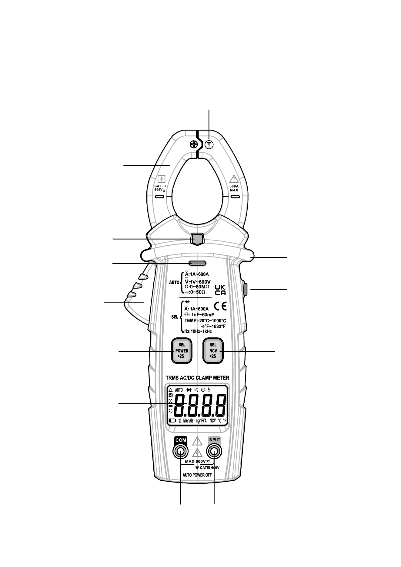
FRONT PANEL
Figure 1
10
11
9
2
3
4
5
6
1
12
7 8
10
11
9
2
3
4
5
6
1
12
7 8

8
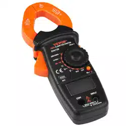
1. Jaws
Used for clamping the conductor for current
measurements. The conductor should be positioned at
the center of the jaws during measurement.
2. Light
3. Red LED
An indicator used in non-contact ac voltage detection
and continuity test.
4. Trigger
Used to open and close the jaws.
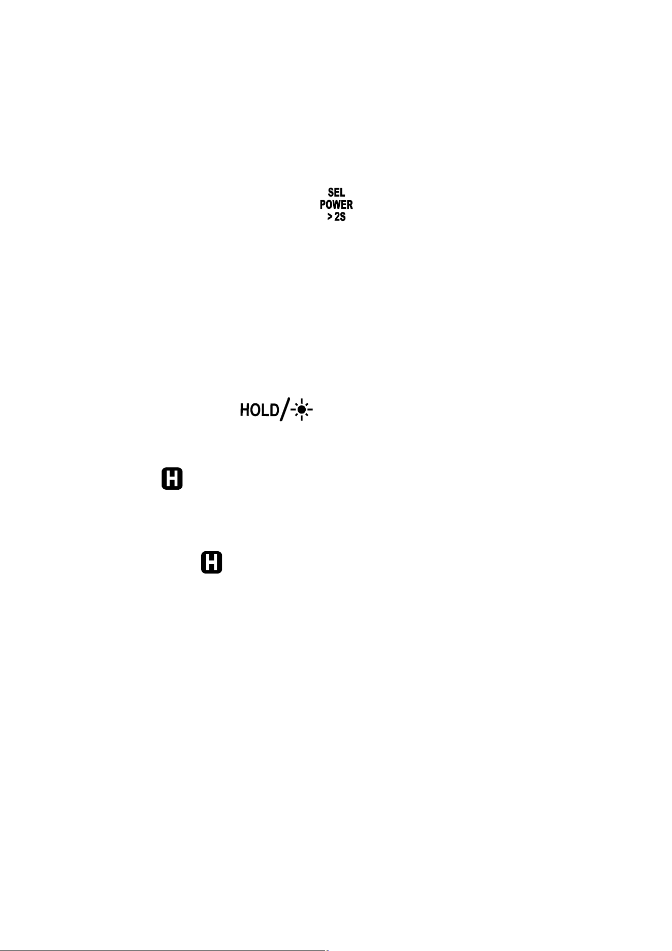
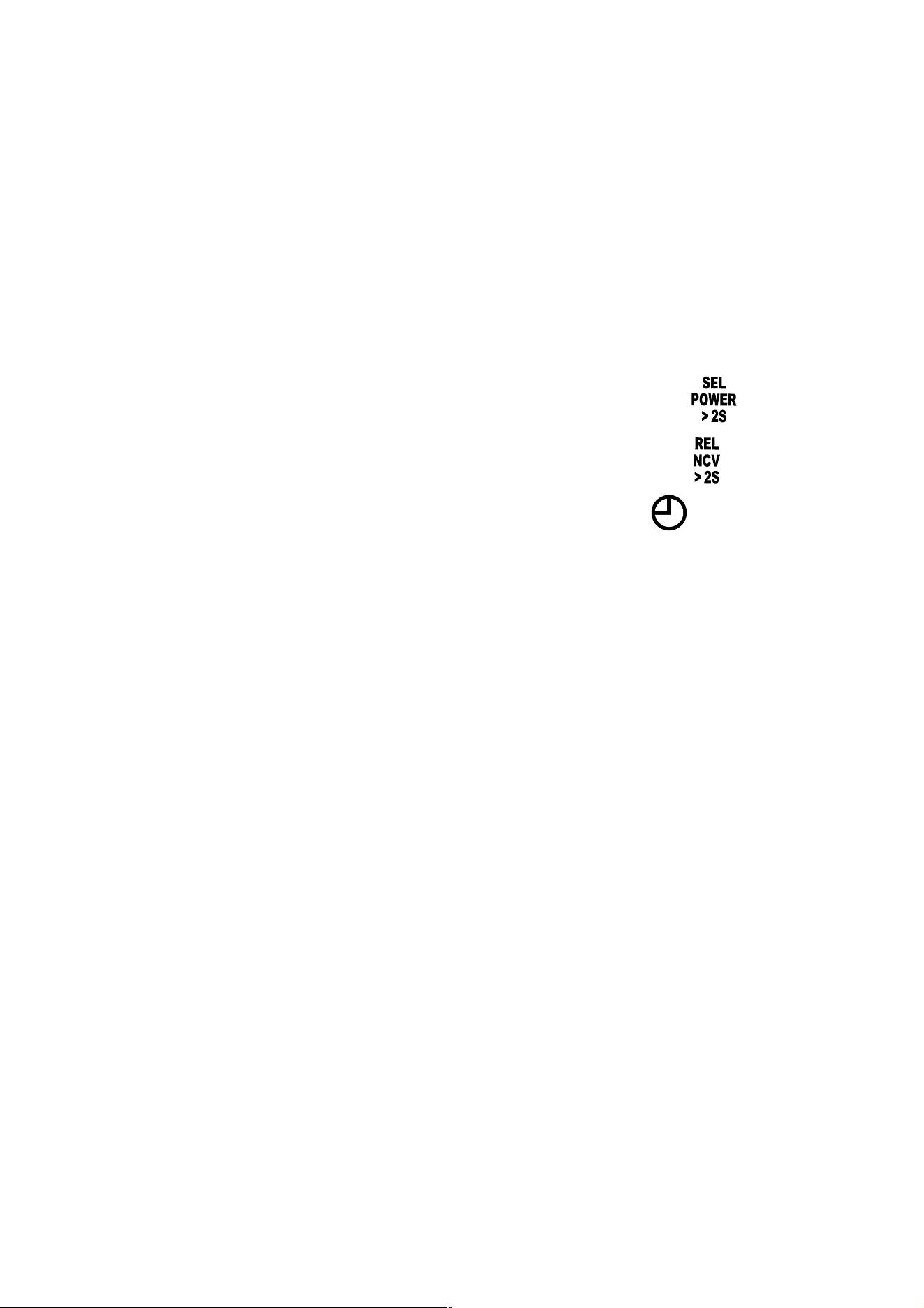
5. " " Button
Briefly press this " " button to switch among
auto-selection measurement function ( " " appears),
diode test function, DC current measurement function,
capacitance measurement function, Celsius temperature
measurement function, and Fahrenheit temperature
measurement function.
Press and hold down this button for about 2 secs to turn
on or off the meter.
6. Display
3
5
/6 digits LCD.
9
7. " COM " Terminal
Plug-in connector for the black test lead.
8. " INPUT " Terminal
Plug-in connector for the red test lead.
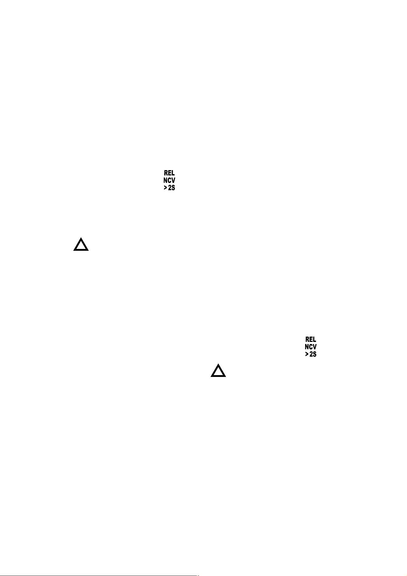
9. " " Button
In dc current measurement function, briefly press this
" " button to zero the display before measurement.
Briefly press again to undo the zeroing.
In other measurement functions, briefly press this
button to enter/exit Relative mode.
Press and hold down this button for about 2 secs to
enter/exit the non-contact ac voltage detection function.
10. " " Button
Briefly press this " " button to enter or exit
Data Hold mode.
With the meter on, press and hold down this button for
to about 2 secs to turn on or off both the light and
backlight. The light and backlight will turn off
automatically after about 2 minutes.
11. Tactile Barrier
Used to prevent finger from touching the conductor
10
under test.
Do not hold the meter anywhere beyond this tactile
barrier.
12. NCV Sensor
This NCV sensor is located at the " " mark near the
top of the clamp. It is used in non-contact ac voltage
detection.
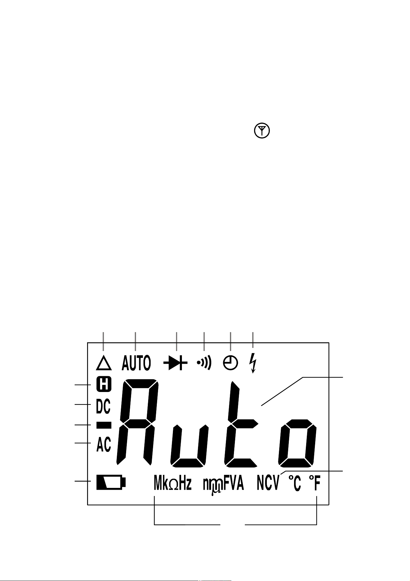
UNDERSTANDING THE DISPLAY
Figure 2
3
9
13
12
10
45678
11
14
1
2
11
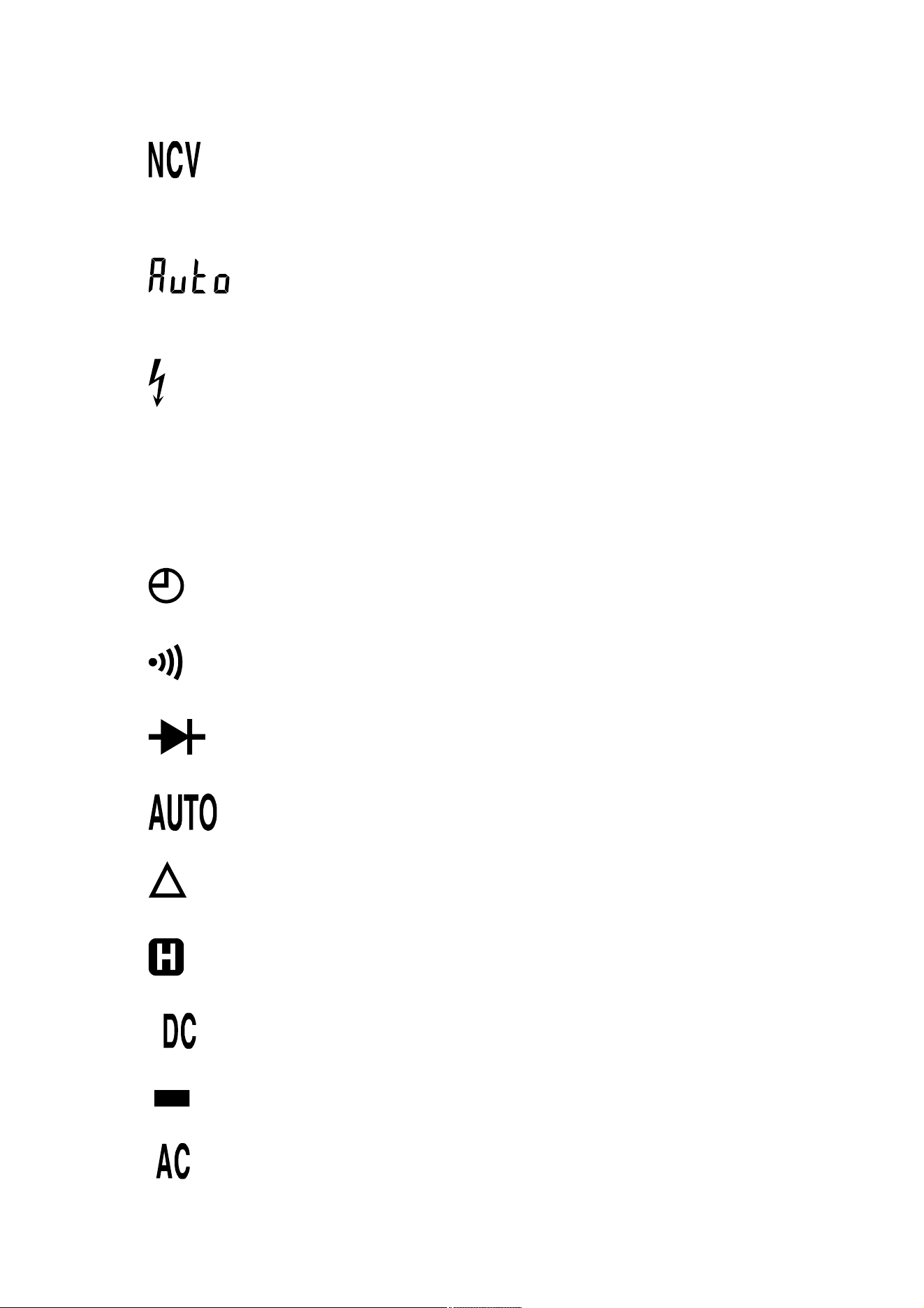
Symbol Meanings:
1. ..... Non-contact ac voltage detection function is
selected.
2. ..... The meter is in the auto-selection
measurement function
3. ..... The meter detects an input voltage > 30V. This
icon is intended to remind you that hazardous
voltage is present and that you must use caution
to avoid electric shock.
4. ..... The automatic power-off feature is enabled.
5. ..... Continuity test function is selected.
6. ..... Diode test function is selected.
7. ..... Autorange mode is active.
8. ..... Relative mode is active.
9. ..... The meter is in Data Hold mode.
10. ..... DC
11. ..... Negative sign
12. ..... AC
12
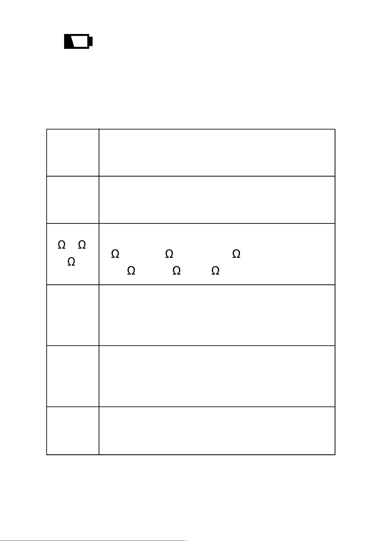
13. ..... The batteries are low and must be replaced
immediately.
14. Units:
V
A
Unit of voltage
V: Volt
Unit of current
A: Ampere
, k ,
M
Hz, kHz
Unit of resistance
: Ohm; k
: Kilohm; M
: Megohm
1M = 10
3
k = 10
6
Unit of capacitance
nF: Nanofarad; µF: Microfarad; mF: Millifarad
1m
F = 10
3
µ
F = 10
6
nF
Unit of frequency
Hz: Hertz; kHz: Kilohertz
1kHz = 10
3
Hz
nF,
µ
F,
mF
°
C,
°
F
Unit of temperature
°C
: Degree Celsius;
°F
: Degree Fahrenheit

13
GENERAL SPECIFICATION
Display: 3
5
/6 digits LCD
Negative Polarity Indication: Negative sign "
-
" shown
on the display automatically
Sampling Rate: About 3 times/sec
Jaw Opening Capability: About 28mm
Max. Measurable Conductor for Current
Measurements: About Ø28mm
Low Battery Indication: " " shown on the display
Battery: 1.5V battery, AAA or equivalent, 2 pieces
Operating Environment: Temperature: 0°C ~ 40°C
Relative Humidity: < 75%
Temperature Coefficient:
0.2 x (specified accuracy)/°C (< 18°C or > 28°C)
Storage Environment: Temperature:
-
30°C ~ 60°C
Relative Humidity: < 85%
IP Degree: IP20
Operating Altitude: 0 to 2000 meters
Size: 200mm
×
75mm
×
40mm
Weight: About 238g ( including battery )
14
SPECIFICATION
Accuracy is specified for a period of one year after
calibration and at 18°C to 28°C, with relative humidity
< 75%.
Except the ranges specified specially, accuracy is
specified from 5% of range to 100% of range.
Accuracy specifications take the form of:
±([% of Reading]+[number of Least Significant Digits])
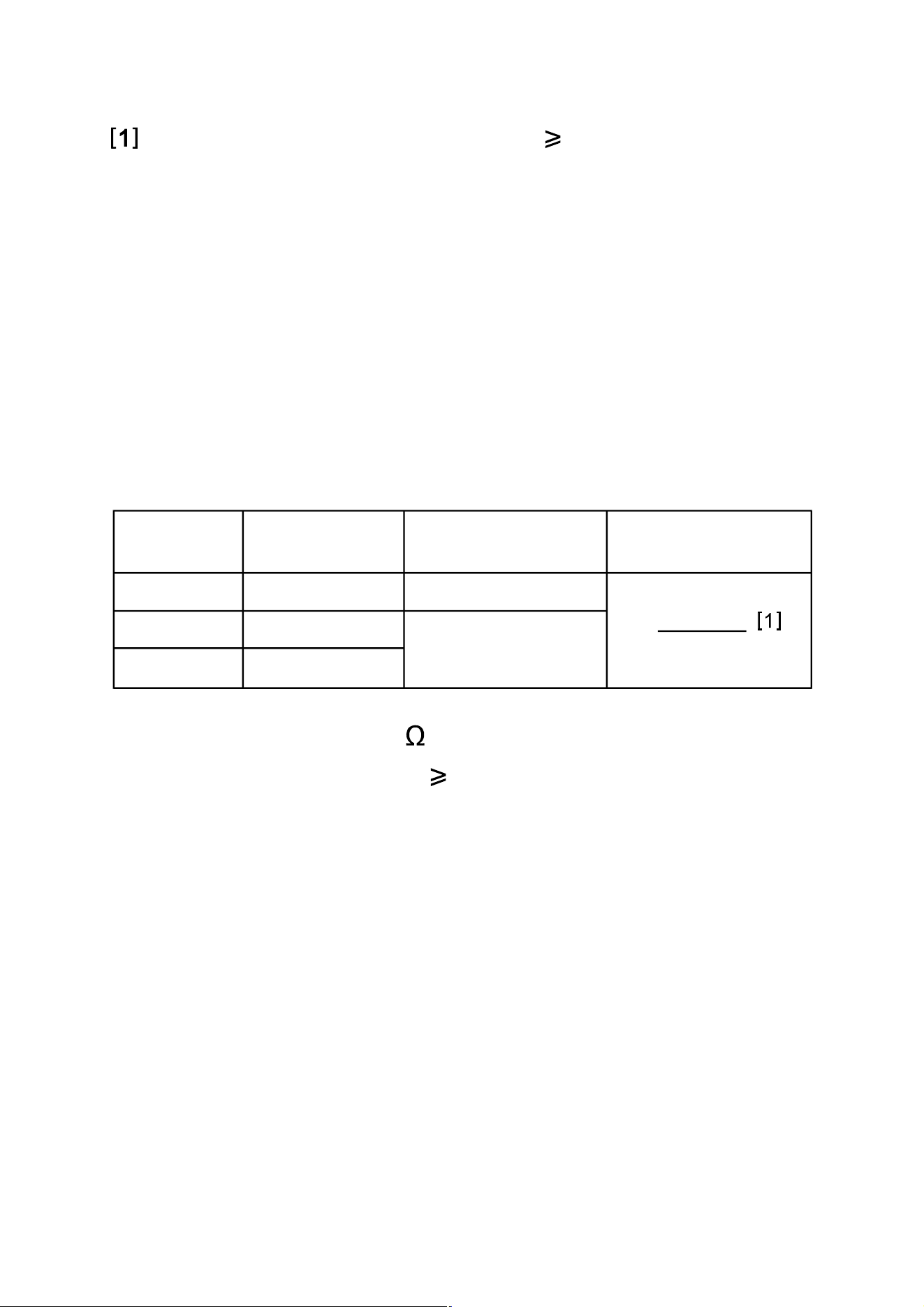
DC Voltage
Input Impedance: 10M
Required Input Voltage: 1V
Max. Allowable Input Voltage: 600V dc
Note:
When the input terminals are open, the display may show
a reading other than zero. This is normal and will not
ResolutionRange Accuracy
6V
60V
600V
0.001V
0.01V
0.1V
± (0.8% + 5)
Overrange
Indication
15
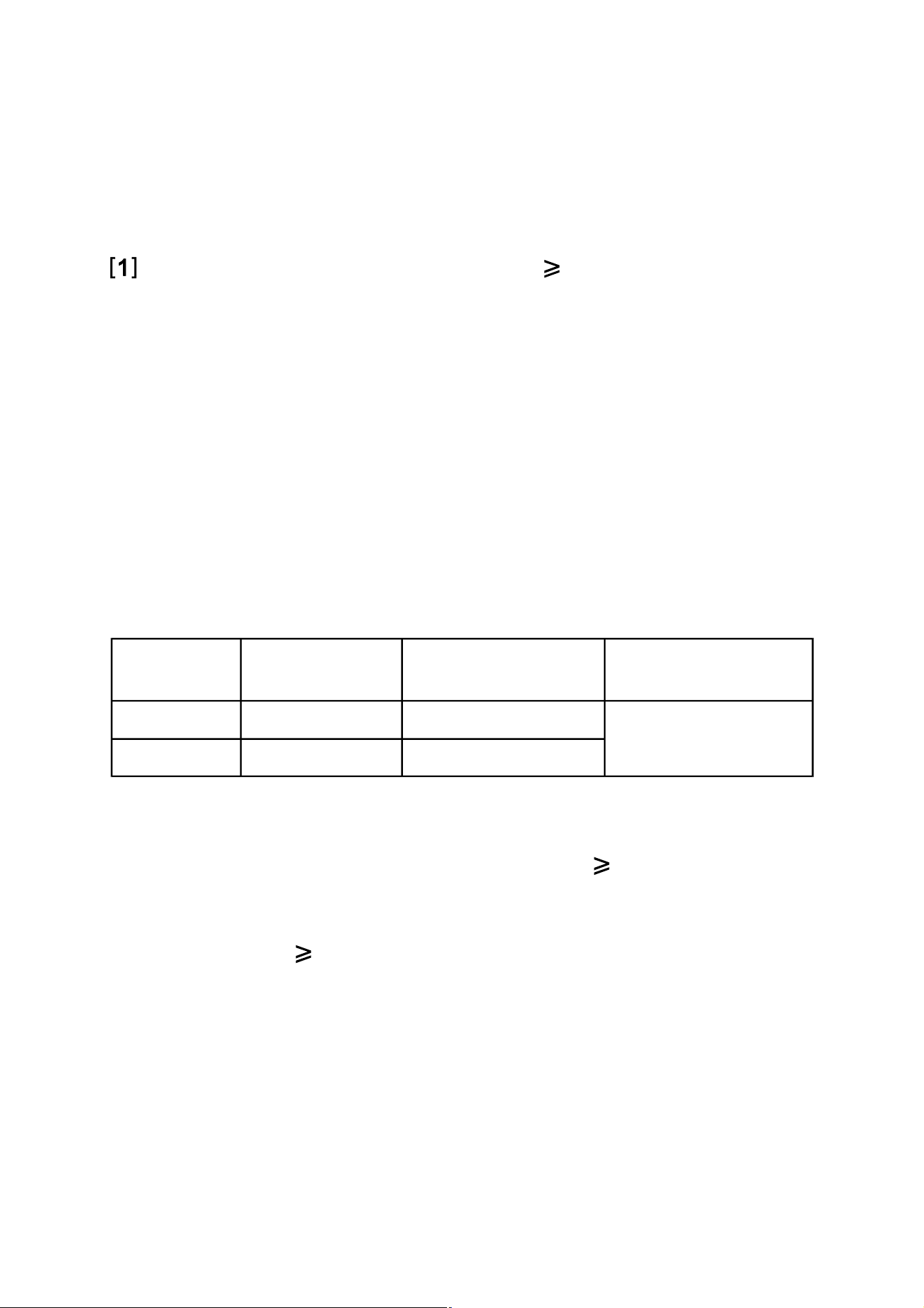
Input Impedance: 10M
Required Input Voltage: 1V
Frequency Range:
40Hz - 400Hz ( only for 6V range )
40Hz - 1kHz ( only for 60V and 600V ranges )
Note: Except for sine wave signal and triangular wave
signal measurements, accuracy specifications for
ac voltage measurements do not apply to
measurements of signals whose frequencies are
> 200Hz.
Reading: True rms
Max. Allowable Input Voltage: 600V ac
ResolutionRange Accuracy
6V
60V
600V
0.001V
0.01V
0.1V
± (1.2% + 5)
± (0.8% + 5)
Overrange
Indication
affect measurements.
If the voltage being measured is 600V, the built-in
buzzer will sound. If the voltage is > 610V, the display
will show " OL ".
AC Voltage
16
ResolutionRange Accuracy
60A
600A
0.01A
0.1A
± (3% + 10)
Overrange
Indication
" OL " shown
on the display
± (3% + 6)
Note:
1. The current to be measured must be 1A.
2. For measurements in 600A range, if the current being
measured is 610A, the display will show " OL ".
Note:
When the input terminals are open, the display may show
a reading other than zero. This is normal and will not
affect measurements.
If the voltage being measured is 600V, the built-in
buzzer will sound. If the voltage is > 610V, the display
will show " OL ".
DC Current
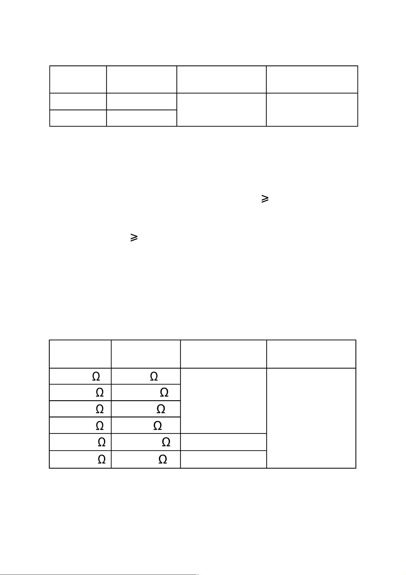
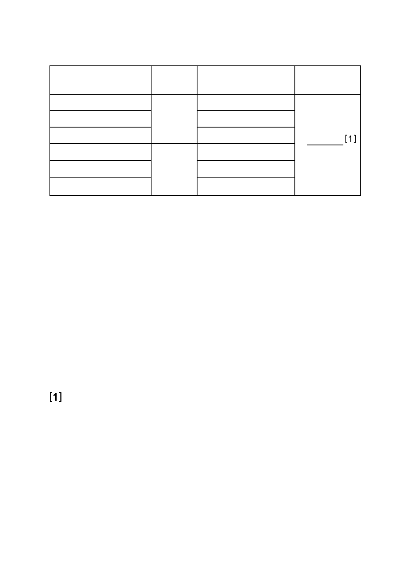
0.001M
0.1k
0.001k
0.01k
0.1
± (1.0% + 5)
0.01M ± (3.0% + 10)
600.0
6.000k
60.00k
600.0k
6.000M
60.00M
± (1.5% + 5)
" OL " shown
on the display
ResolutionRange Accuracy
Overrange
Indication
17
ResolutionRange Accuracy
60A
600A
0.01A
0.1A
± (2.5% + 6)
Overrange
Indication
" OL " shown
on the display
Frequency Range: 50Hz ~ 60Hz
Reading: True rms
Note:
1. The current to be measured must be 1A.
2. For measurements in 600A range, if the current being
measured is 610A, the display will show " OL ".
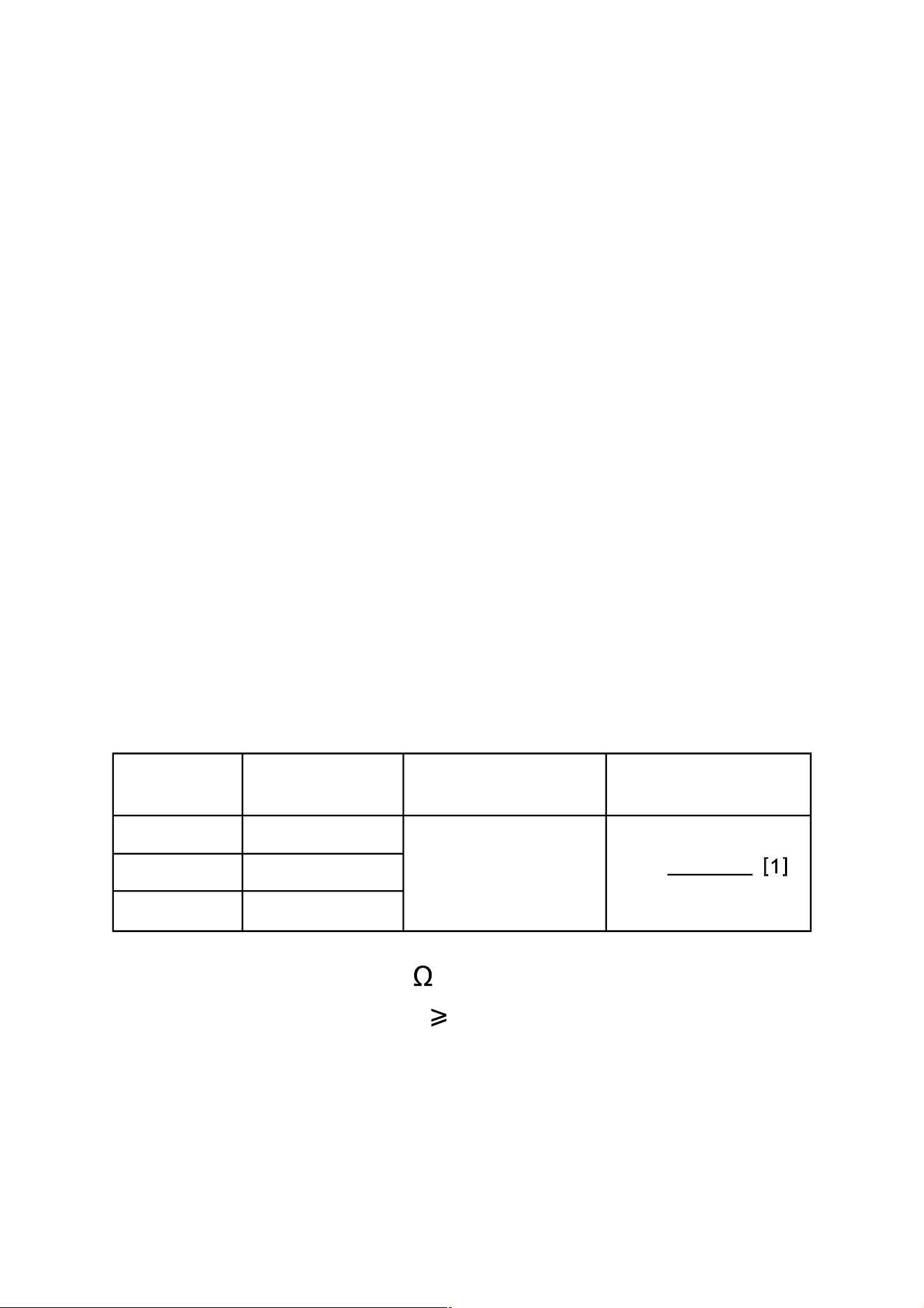
Resistance
AC Current
18
± (1.5% + 10)
Input Voltage: 90V ac ~ 600V ac
Range Resolution Accuracy
99.99Hz
999.9Hz
0.01Hz
0.1Hz
Remark
Autorange
± (5.0% + 5)
Resolution AccuracyRange
60.00nF
600.0nF
6.000µF
600.0µF
60.00µF
6.000mF
0.1µF
0.01µF
0.001µF
0.1nF
0.01nF
0.001mF
Remark
Autorange
Note:
1. For measurements > 60mF, accuracy is not specified.
2. Use the Relative mode to subtract the residual
capacitance of the meter and leads.
Frequency
Capacitance
6.000nF 0.001nF
not specified60.00mF 0.01mF
± (5.0% + 20)
19
Temperature Sensor: K Type thermocouple
Note:
1. Accuracy does not include error of the thermocouple
probe.
2. Accuracy specification assumes ambient temperature
is stable to ±1°C. For ambient temperature changes of
±5°C, rated accuracy applies after 1 hour.
3. The meter's operating temperature must be between
18°C and 28°C; otherwise measurement accuracy is
not guaranteed.
The display will show " OL " if the temperature being
measured is higher than 1300°C ( 2372°F ) or lower
than
-
55°C (
-
67°F ).
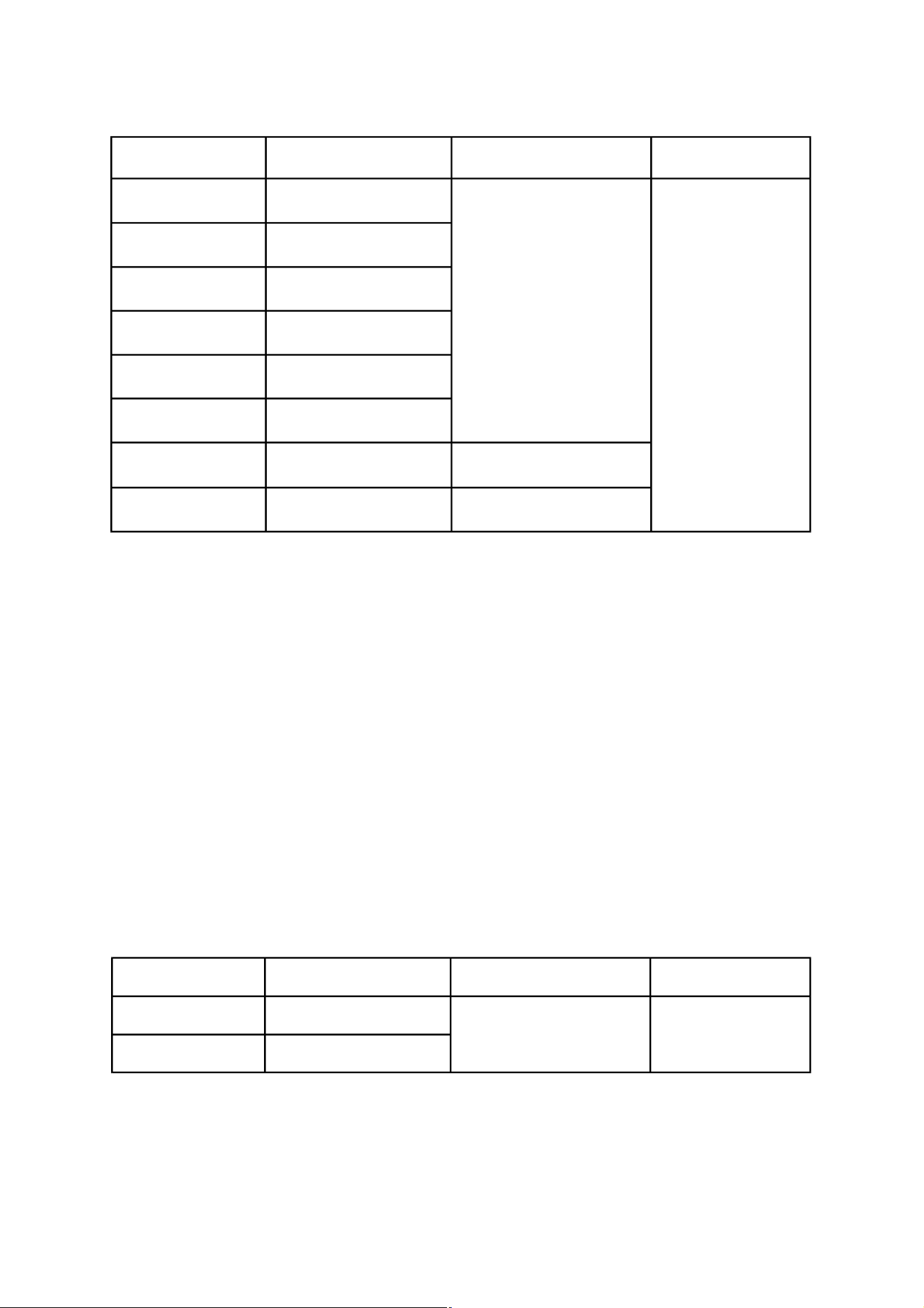
1°C
± (6.0% + 9°F)
1°F
± (1.8% + 9°F)
-
20°C ~ 0°C
0°C ~ 400°C
400°C ~ 1000°C
-
4°F ~ 32°F
32°F ~ 752°F
752°F ~ 1832°F
± (1.5% + 7°F)
Reso-
lution
Range Accuracy
Overrange
Indication
± (6.0% + 5°C)
± (1.5% + 4°C)
± (1.8% + 5°C)
Temperature
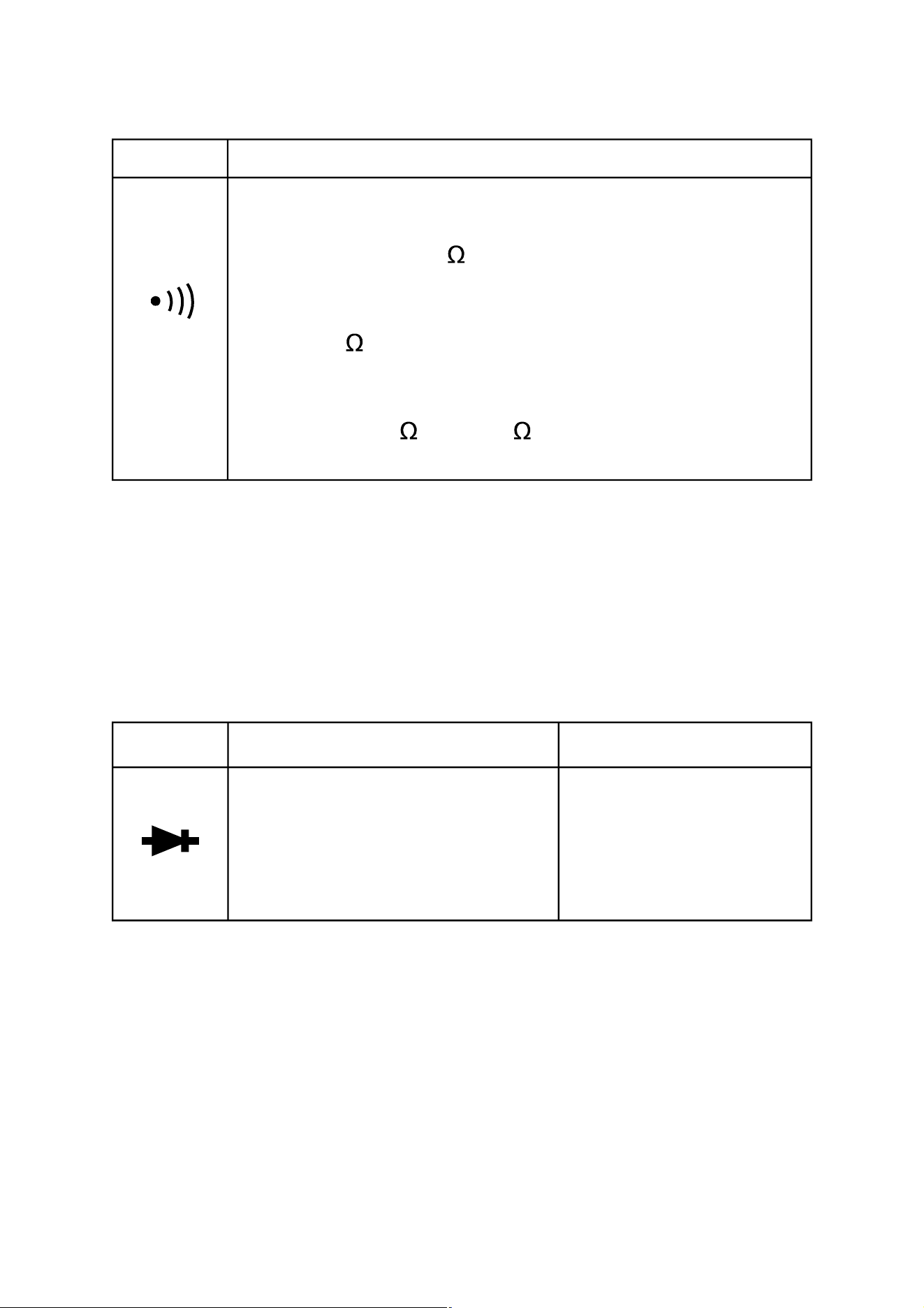
Diode Test
RemarkRange Description
Open Circuit Voltage:
about 4V
The approximate forward
voltage drop of the diode
under test is displayed.
20
Range Description
The built-in buzzer will sound if the resistance is
less than about 50
.
.
The buzzer will not sound if the resistance is more
than 100 ..
The buzzer may or may not sound if the resistance
is between 50 . and 100 ..
Continuity Test
OPERATING INSTRUCTION
Turning on/off the Meter
Press and hold down the " " button for about 2 secs
to turn on or off the meter.
Data Hold Mode
Briefly press the " " button to enter the Data Hold
mode. The present reading is held on the display, and the
symbol " " appears on the display as an indicator.
To exit the Data Hold mode, briefly press this button again.
The symbol " " disappears.
Note:
Non-contact ac voltage detection function does not have
Data Hold mode.
Using Relative Mode
Relative mode is available in some functions. Selecting
21
Relative mode causes the meter to store the present
reading as a reference for subsequent measurements.
1. Set the meter in desired function or range.
2. Connect the meter to a desired circuit ( or object )
properly to get a reading, which is to be used as a
reference for subsequent measurements.
3. Briefly press the " " button once. The meter enters
the Relative mode and stores the present reading as a
reference for subsequent measurements. The symbol
" " appears on the display as an indicator and the
display reads zero.
4. In subsequent measurements, the display shows the
difference between the reference and the new
measurement.
5. To exit the Relative mode, briefly press this " "
button again. The symbol " " disappears.
Note:
1. When you use Relative mode, the actual value of the
object under test must not exceed the full-scale value
of the present range.
2. To avoid wrong measurement result, do not enter
Relative mode when Data Hold mode is active.
22

23
3. When the display shows " OL ", it means overrange.
4. Except for capacitance function, the meter enters
manual ranging in the present range when you enter
the Relative mode.
5. For frequency, temperature, diode and continuity test
functions and non-contact ac voltage detection function,
Relative mode is not available.
6. In dc current measurement function, the " " button
is used to zero the display.
Measuring DC or AC Voltage
1. Connect the black test lead to the " COM " terminal,
and the red test lead to the " INPUT " terminal.
2. Briefly press the " " button until the display shows
" ". Now the meter is in the auto-selection
measurement function.
3. Connect the test leads across the source or circuit to
be tested.
4. The display shows the value of the voltage being
measured.
If the voltage being measured is a DC voltage, the
24
display will show the symbol " " as an indication. If
the voltage being measured is an AC voltage, the
display will show the symbol " " as an indication.
For DC voltage measurements, the polarity of the red
test lead connection will be indicated as well.
Note:
1. To avoid electric shock to you or damage to the meter,
do not apply a voltage higher than 600V between the
terminals.
2. The input voltage must be 1V.
Measuring DC Current
1. Make sure that all the test leads have been removed
from the meter.
2. Briefly press the " " button until both the symbol
" " and the unit " A " are shown on the display.
3. If the display shows a reading other than zero, briefly
press the " " button once to zero the display.
4. Press the trigger and clamp the jaws around one
conductor to be tested. Make sure that the jaws are
perfectly closed.

Note:
Only one conductor should be clamped. Measuring
two or more conductors at the same time will
produce wrong reading.
The conductor should be positioned at the center
of the jaws; otherwise there will be an additional
measurement error, which is typically not more than
about 2% of reading.
5. Read the reading on the display.
Note:
1. After you turn on the meter, wait about 5 to 10 minutes
to allow the meter to warm up before you start current
measurement. This is necessary for accurate
measurements.
2. The reading on the display also indicates the current's
direction: A positive reading indicates that the current
direction is from the meter's front to its back. ( Tip:
Current direction is the opposite of electron flow
direction. )
3. Don't use the meter to measure a circuit's current if the
circuit contains a voltage > 600V.
25

26
Measuring AC Current
1. Make sure that all the test leads have been removed
from the meter.
2. Briefly press the " " button until the display shows
" ". Now the meter is in the auto-selection
measurement function.
3. Press the trigger and clamp the jaws around one
conductor to be tested. Make sure that the jaws are
perfectly closed.
Note:
Only one conductor should be clamped. Measuring
two or more conductors at the same time will
produce wrong reading.
The conductor should be positioned at the center
of the jaws; otherwise there will be an additional
measurement error, which is typically not more than
about 2% of reading.
4. Read the reading on the display.
Note:
1. After you turn on the meter, wait about 5 to 10 minutes
to allow the meter to warm up before you start current
measurement. This is necessary for accurate
measurements.

27
2. Don't use the meter to measure a circuit's current if the
circuit contains a voltage > 600V.
Measuring Resistance
1. Connect the black test lead to the " COM " terminal,
and the red test lead to the " INPUT " terminal.
2. Briefly press the " " button until the display shows
" ". Now the meter is in the auto-selection
measurement function.
3. Connect the test leads across the resistor to be tested.
4. Wait until the reading is stable, then read the reading
on the display.
Note:
1. For measurements > 1M , the meter may take a few
seconds to stabilize reading. This is normal for high
resistance measurements.
2. When the input terminals are open, " OL " will be
displayed as an overrange indication.
3. Before measurement, disconnect all power to the
circuit to be tested and discharge all capacitors
thoroughly.
Diode Test
1. Connect the black test lead to the " COM " terminal,
and the red test lead to the " INPUT " terminal.
2. Briefly press the " " button until the display shows
the symbol " ".
3. Connect the red test lead to the anode of the diode to
be tested, and the black test lead to the cathode of the
diode.
4. The display shows the approximate forward voltage
drop of the diode.
Continuity Test
1. Connect the black test lead to the " COM " terminal,
and the red test lead to the " INPUT " terminal.
2. Briefly press the " " button until the display shows
" ". Now the meter is in the auto-selection
measurement function.
3. Connect the test leads across the circuit to be tested.
4. If the resistance is less than about 50 , the built-in
buzzer will sound.
28
29
Note:
Before test, disconnect all power to the circuit to be tested
and discharge all capacitors thoroughly.
Measuring Capacitance
1. Connect the black test lead to the " COM " terminal,
and the red test lead to the " INPUT " terminal.
2. Briefly press the " " button until the display shows
a capacitance measurement unit ( nF ). Now the meter
is in the capacitance measurement function.
3. If the display shows a reading other than zero, briefly
press the " " button to zero the display; the display
will show the symbol " " to indicate that the meter is
in Relative mode.
Note: Do not short the test leads together.
4. Connect the test leads across the capacitor to be
tested.
5. Wait until the reading is stable, then read the reading
on the display.
Note:
1. Before measurement, make sure that the capacitor to

30
be tested has been discharged thoroughly.
2. For measurements > 10µF, it may take about 30 secs
for the meter to complete measurement and stabilize
reading.
Measuring Frequency
1. When the meter is in the AC voltage measurement
function ( both " " and " V " are displayed ) and
Data Hold mode is off, briefly press the " " button
once. The meter switches to the frequency
measurement function, and the display shows a
frequency measurement unit.
Note: For information about how to change the meter
to the AC voltage measurement function, see
the relevant instructions in the " Measuring DC
or AC Voltage " section.
2. Connect the test leads across the source or circuit to
be tested.
3. Read the reading on the display.
Note:
1. Only when the meter is in the AC voltage

31
measurement function and the Data Hold mode is off
can you change the meter to the frequency
measurement function by briefly pressing the " "
button.
2. For frequency measurements, range change is
automatic.
Measurement range is: 10Hz ~ 1kHz
Measuring Temperature
To avoid possible damage to the meter or other
equipment, remember that while the meter is rated
for
-
20°C to +1000°C and
-
4°F to 1832°F, the K Type
Thermocouple provided with the meter is rated to
250°C. For temperature out of that range, use a
higher rated thermocouple.
The K Type Thermocouple provided with the meter
is a present, it is not professional and can only be
used for non-critical measurements. For accurate
measurements, use a professional thermocouple.
Note

32
1. If you want to perform Celsius temperature
measurement, briefly press the " " button until the
display shows " °C ". If you want to perform Fahrenheit
temperature measurement, briefly press the " "
button until the display shows " °F ". The display
shows the compensation temperature, which is an
approximate value of the environment temperature.
( To measure environment temperature accurately, you
must connect K Type thermocouple to the meter. )
2. Connect the negative "
-
" plug of the K Type
thermocouple to the " COM " terminal, and the positive
"
+
" plug of the K Type thermocouple to the " INPUT "
terminal.
3. Connect the sensing end of the thermocouple to the
object to be tested.
4. Wait a while until thermal equilibrium between the
thermocouple probe and the object is reached, then
read the reading on the display.
Non-Contact AC Voltage Detection
1. To select the non-contact ac voltage detection function,
33
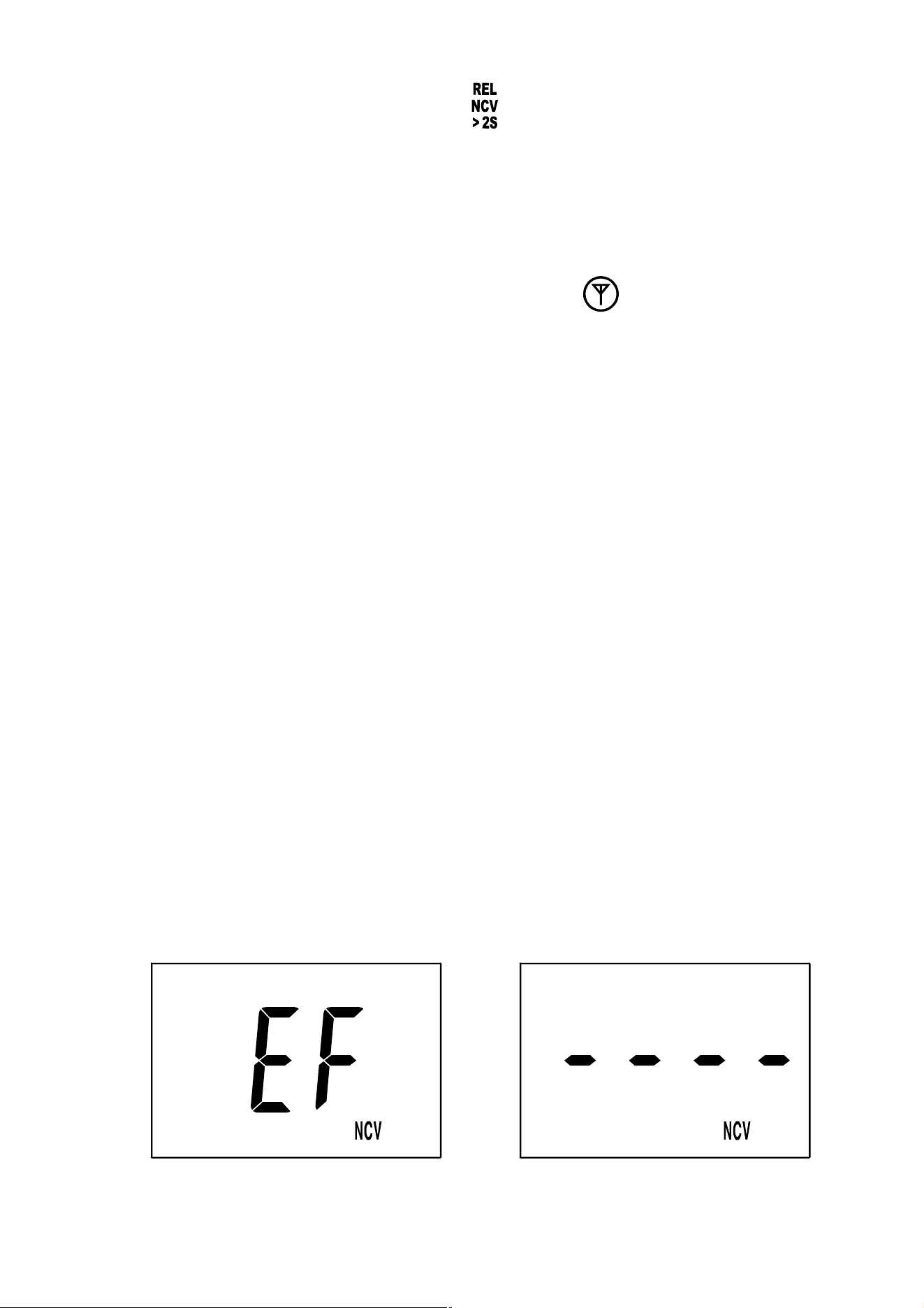
press and hold down the " " button for about 2 secs.
The display shows the symbol " NCV " indicating that
the meter is in the non-contact ac voltage detection
function ( see Figure 3 ).
2. Move the NCV sensor at the mark " " on the meter
clamp close to the object to be tested. When the meter
detects electric field generated by ac voltage, the red
LED on the meter will flash and the meter will indicate
the intensity of the electric field being detected. The
intensity of the electric field being detected is indicated
by the number of the bar-graph segments shown at the
vertical center of the display ( see Figure 4 ), the
flashing rate of the red LED, and the beeping rate of
the built-in buzzer. The higher the intensity of the
electric field being detected, the larger the number of
the bar-graph segments shown on the display, the
faster the flashing rate of the red LED, and the faster
the beeping rate of the buzzer.
Figure 3 Figure 4

34
Note:
1. Detection Range: 90V - 600V
Required Voltage Frequency: 50Hz/60Hz
2. The optimal detecting position of the meter is at the
" " mark on the clamp.
3. If an ac voltage is not within the meter's detecting
capacity/distance, the meter can not detect this voltage.
4. The meter's electric field intensity indication is affected
by the magnitude of the ac voltage of the conductor
under test, the distance between the meter and the
conductor, the insulation of the conductor, and etc.
5. Because of the meter's detection limit, a line ( or
conductor) under test may be electrically live even if
the buzzer does not sound, the red LED does not flash
and the display does not indicate the presence of
electric field.
6. Before and after each use, verify the meter's operation
by detecting a known AC voltage. Do not use the meter
if it operates abnormally or malfunctions.
7. To avoid electric shock, do not touch any conductor
with hand or skin.
8. To avoid interference, don't perform non-contact ac
voltage detection in an environment with strong
electromagnetic field; otherwise the detection result
may be wrong.
Automatic Power-Off
The meter will turn off automatically and go into Sleep
mode if you have not operated the meter for about 15
minutes.
To disable the automatic power-off feature, make sure that
the meter is off. Then press and hold down the " "
button for about 2 secs while holding down the " "
button. The meter turns on, and the symbol " " is
absent from the display.
MAINTENANCE
Warning
Except replacing batteries, never attempt to repair or
service the meter.
Store the meter in a dry place when not in use. Don't store
it in an environment with intense electromagnetic field.
35

General Maintenance
Periodically wipe the case with a damp cloth and a little
mild detergent. Do not use abrasives or solvents.
Dirt or moisture in the terminals can affect readings. Clean
the terminals as follows:
1. Turn off the meter and remove all the test leads from
the meter.
2. Shake out any dirt which may exist in the terminals.
3. Soak a new swab with alcohol.
4. Work the swab around in each terminal.
If the meter fails, check and replace ( as needed ) the
batteries and/or review this manual to verify proper use of
the meter.
36
37
To avoid false readings, which could lead to
possible electric shock or personal injury,
replace the batteries as soon as the low battery
indicator ( ) appears.
Turn off the meter, remove the test leads from
the meter and the meter clamp from any
conductor under test before opening the case
or the battery cover.
Warning
When the low battery indicator " " appears on the
display, the batteries are not high enough and must be
replaced immediately.
To replace the batteries, remove the screw on the battery
cover and remove the battery cover. Replace the
exhausted batteries with new ones of the same type, make
sure that the polarity connections are correct. Reinstall the
battery cover and the screw.
Replacing the Batteries

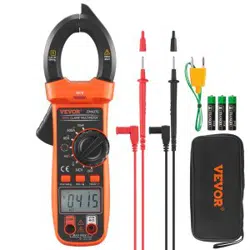
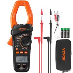
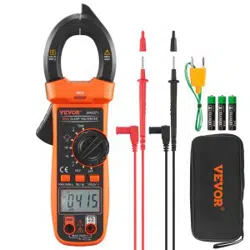
ACCESSORIES
Manual: 1 piece
Test Lead: 1 pair
PRESENT
K Type Thermocouple: 1 piece
NOTE
1. This manual is subject to change without notice.
2. Our company will not take the other responsibilities for
any loss.
3. The contents of this manual can not be used as the
reason to use the meter for any special application.
38
39
DISPOSAL OF THIS ARTICLE
Dear Customer,
If you at some point intend to dispose of
this article, then please keep in mind that
many of its components consist of valuable
materials, which can be recycled.
Please do not discharge it in the garbage
bin, but check with your local council for
recycling facilities in your area.
V221205