Instruction
Instruction
Manual
Manual
ELECTRIC
ELECTRIC
REBAR
REBAR
BENDERS
BENDERS
&
&
REBAR
REBAR
CUTTERS
CUTTERS
MODEL:
MODEL:
RB
RB
-25
-25
RB-32
RB-32
RB
RB
C-2
C-2
5
5
RBC-32
RBC-32

1
Please read the operation manual carefully before
operate the machine and keep it for the reading in
future
1. Safety
1.1
SAFETY RULES
1.1.1.GENERAL SAFETY RULES
Do not attempt to operate until you have read thoroughly
and understand completely all instructions, rules, etc.
contained in this manual. Failure to comply can result in
accidents involving fire, electric shock, or serious
personal injury. Keep owners manual and review frequently for continuous safe operation.
1. KNOW YOUR MACHINE.
For your own safety, read the owner’s manual carefully. Learn its application and
limitations as well as specific potential hazards pertinent to this machine.
2. KEEP WORK AREA CLEAN.
Disorder area and working table will cause accident.
3. DO NOT USE IN DANGEROUS ENVIRONMENTS.
Do not use power tools in damp or wet locations, or expose them to rain. Keeps work area well
illuminated.
4. KEEP NON-PROFESSIONAL PEOPLE AWAY.
All visitors should be kept at a safe distance from work area.
5. USE THE SUITABLE TOOLS, DO NOT FORCE THE MACHINE.
It will do the job better and be safer at the rate for which it was designed.
6. WEAR PROPER APPAREL.
Avoid loose clothing, gloves ,neckties, rings, bracelets, or jewelry, which could be caught
in moving parts. Non-slip footwear is recommended. Wear protective hair covering to
contain long hair.
7. THE MACHINE SETTING
Bender should be on flat and steady ground before starting.
Any shaking may cause imprecise work.To avoid the safety accident, please make sure the
machine is not shaking before working.
8. OPERATION IS OFF, MAINTAIN THE MACHINE
Keep the machine clean and safe. After operation, clean and remove dust and scrap iron in
the main gear and body
9. USE RECOMMENDED ACCESSORIES.
Before the service, replaces the fitting, or perhaps the assembly and assembles the motor,
must cut-off machine's power source from the power source place (the note: Carries on the
operation by the specialists).
10.POWER SUPPLY
①.The power source ,please connect with the single-phase 110V or 220V (see the parameter in
the machine ) power source to uses

2
②.when connects to the power source RB-25 and RBC-25 must use 3.5 ~ 5.5sq (cv) the power
line, RB-32 and RBC-32 must use 4 ~ 6.5sq (cv) the power line. The power line is must
maintain can below 30~40m to assure operation normally
※ Reference--------in situation of use extend line
This product is set in the situation of far distance from the power to use the extend line to
connect, according to the thickness of line and the different of current capacity , so must use
the above provisions. Extension line. Use line is too long or too thin will make the loss of
electric current and overload of the voltage, lead to edge of the wiring insulation rapid turn
heat,then insulating ability to reduce ,finally to leak electric poaer or fire.besides will weaken
the motor output force, internal electrical circuit easy to failure .
to began using the Line from the power line connect point must suit to the provisions of
the above extension line, also do not mean operation near the electric power supply is good, in
situation of long distance operation,please refer to the table to using appropriate degree of
power line according to distance.
(wire)max.longth
RB-25 / RBC-25
RB-32 / RBC-32
Diameter of wire / wire
size
Diameter of wire/ wire
size
15m
2.0sq X 3C
3.5sq X 3C
25m
3.5sq X 3C
4.5sq X 3C
40m
5.5sq X 3C
6.5sq X 3C
1.1.2 Additional safety rules
①.When the machine is running, don't clean or remove scraps
②.Do not remove or modify the warning signs even not replace or any may cause confusion of
marks.
③.Carefully reading the manual before operating the machine.
④.The machine on ground correctly, to avoid hazard shock.
⑤.Not away till the machine is off.
⑥.Before replace the module the machine should stop completely .
⑦.before starting, confirm. determine the correct, bending Angle.
⑧.Do not to put any tools on platform before starting work, to avoid accidents .
⑨.Use appropriate tools to adjust machine.
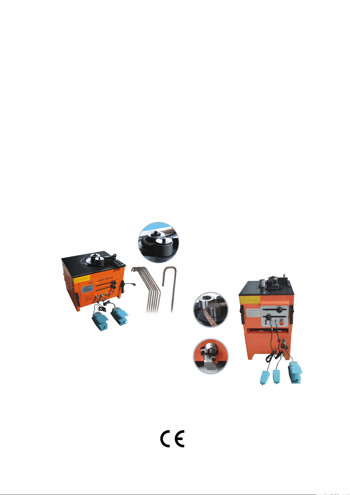
1.2. Warning signs:
This machine has warning symbols attached on it as shown below to ensure proper and safe
operation.
3
These symbols are used on the machine to indicate points or instance of specific danger to
operating personnel.
Do not remove safety symbols from the machine.
The safety have two grade that are Danger and Attention in this manual:
Dangerous—Means the dangerous by the wrong operating and lead death and GBH.
Attention
—
Means the dangerous by the wrong operating and lead the hard damage of
common or venial harm. Attention can help the user to know the result of ignore the
warning and recognize the dangerous and avoid the dangerous.
1. Avoid the damage
Danger
Don’t put your hand or head inside the guard fence, if not will harm yourself.
Don’t touch the button with wet hand, if not will get the electric shock.
Every work include the installation, test and inspection & maintenance need to be
done by the professional technician.
2. Transit and Installation
Attention
Please use the proper rise and fall tools to transit the equipment when transit the
equipment to avoid the damage and accident.
Flow the operation manual to install the equipment.
Check and confirm the installation place and the position of the slitting rewinder.
Don’t let the machine get the violent strike or hit when transit the machine.
Don’t lift or hang the motor when transit as by this will damage the motor.
Don’t test the machine if there is lack of or damage any electricelement.
3. Setting Line
Danger
Don’t connect the chief power supply to the fan-out of creepage protection button.
Please cut off the power supply and confirm by checking when setting the line or
inspect.
Setting the line after installation, if not will lead accident.
Don’t press or clamp the cable, not damage or refute arbitrarily, either. Unless will
lead the electric shock.
4. Attempt Running
Attention
Check the whole machine and confirm the suddenly start-up can not damage the
equipment.
Adjust the three phase relatives between the control tank and each motors to confirm
the turning position of each motor is right.
5. Operation
4
Attention
Don’t touch the running part of the slitting folder by your hand in the period of early
testing to avoid the hurt.
Don’t do any modification for the equipment unless have the technician’s help from
BS. If not BS will not bear any duty of the result.
6. Other Attention Item
Attention
The completely inspection and attempt running are needed before using after leave
unused for a long time.
It is not allowed to operating or maintain the machine when the operator is not
clear-headed by drink or tired.
Please use the spare parts from BS for the maintenance and part change. BS will not
guarantee to keep it in good repair if the customer damage the machine by using the
spare parts from other company
Main Parameters
Model
RB-25
RBC-25
RB-32
RBC-32
Voltage ± 5%
110V/230V AC
only
110V/230V AC
only
110V/230V AC
only
110V/230V AC
only
Wattage
1700W/1600W
1700W/1600W
2800W/3000W
2800W/3000W
Net weight
91 KGS
136 KGS
175 KGS
225 KGS
Cutting speed
5-6 s
5-6 s
6-7 s
6-7 s
Max rebar
diameter
¢25mm
¢25mm
¢32mm
¢32mm
Min rebar
diameter
¢6mm
¢6mm
¢6mm
¢6mm
Machine size
450*500*440mm
500*450*790mm
600*580*470mm
600*580*980mm

5
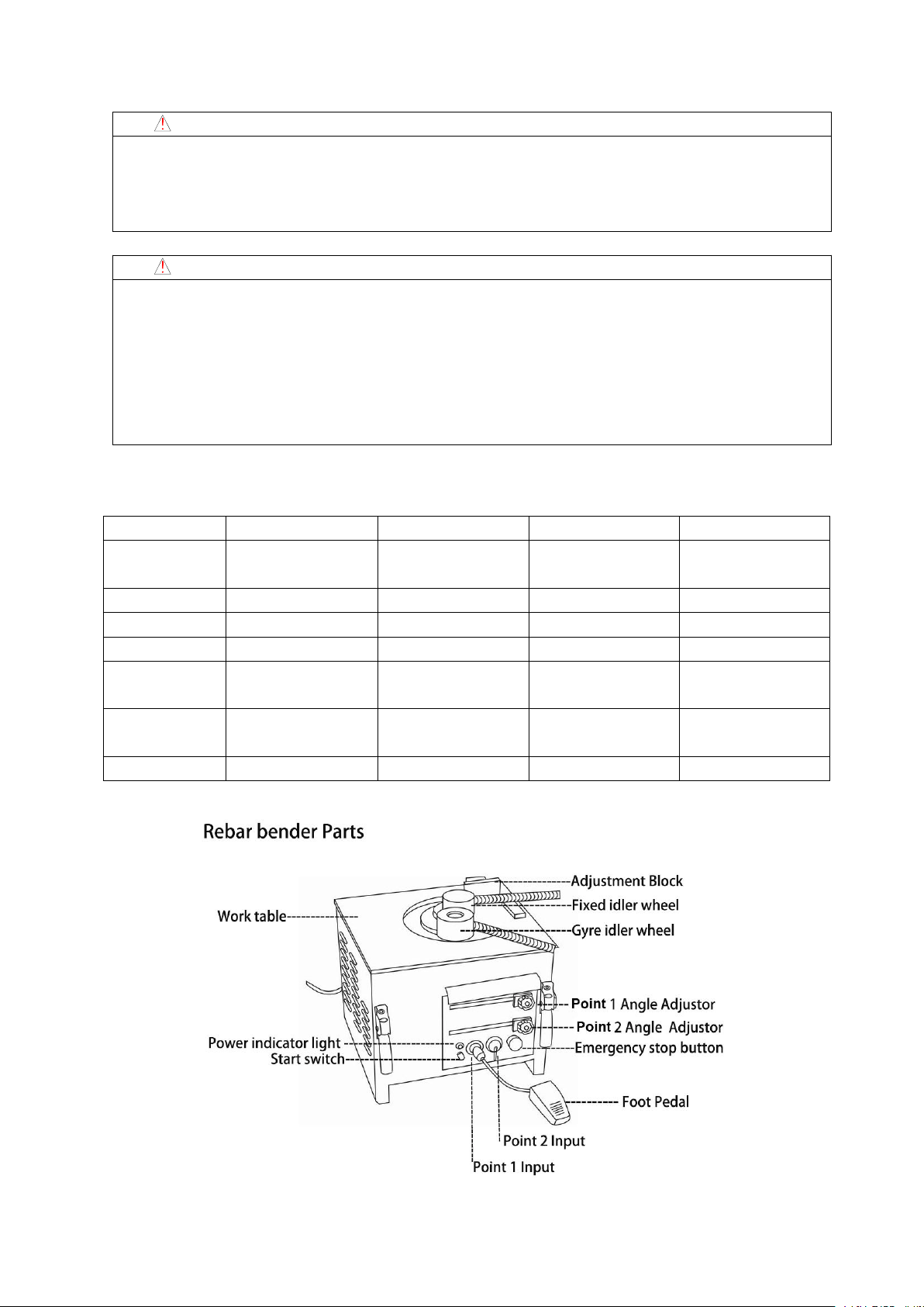
2.Means of operation
2.1 Using methods
① When the power line connection to the 110V/220V power source and the power
indicator light shone on namely mean of the machine operation preparation finishes may go
on the normal work.
② The fixed idler wheel, the move idler wheel and the steel bar adjustment block's spacing
needs to make the corresponding adjustment according to the specification of the steel bar.
③ The foot switch connection to point1,2 will make more convenient to go on work .
Point 1, connect to work - angle set by is point 1, press the START switch or
point1foot pedal switch control to operation.
Point 2,connect to work, The angle setby is point 2, through the foot switch control
operation, this time the point1 angle set by handle must establish with point 2
in the same level angle or is bigger than the point 1 angle . while also after the
angle handle setting must fix well the handle nut or when the machine
operation will become loose.
④ Adjust the angle that you need by through move Left or right, after angle adjustment is
set accurately, assure that angle setting handle is fixed .
⑤The operator must stand outside of the rebar bender operation’s direction.
⑥ when press the starting switch or the foot switch will bend the rebar to the angle which
you have set
⑦ when you find some abnormal during the operation you must press down emergency
stopped to closes down the machine’operation.
⑧sure to remember, when bending processing, the angle of point 1 must be bigger than
point 2, otherwise the machine cannot the normal operation. (This is for RB-25 AND
RBC-25 , RB-32 AND RBC-32 is no problem .)
⑨ under situation of use foot switch beyond control machine’operation when please
through press nearby power light's hand switch test machine whether to revolve judges the
foot switch whether to present the breakdown.
Note: ① when press the emergency switch to run the machine,the move idler wheel will
reture to its position.
② under the work situation of point 2 bending, the point 1 handle’position must be
keep the same level angle with point 2 or to set smaller in the angle 5 degrees than
the point 1 and then fix the angle handle, so that not to occure the electricial or the
machine misoperation.

6
※Matching of different wheel(RB-25 / RBC-25 ) :
Rebar
specification
Fixed idler
wheel
Gyre idler wheel
Contemporary
bending capacity
Ø22- Ø25
Ø78
Ø94
1 pcs
Ø16- Ø20
Ø78
Ø94
1-2 pcs
Ø
10-
Ø
13
Ø
78
Ø
94
4-5 pcs
Ø6- Ø13
module
Ø94
3-6 pcs
Special
situation
Possible
customize
Possible customize
※Matching of different wheel(RB-32 RBC-32) :
Rebar
specification
Fixed idler
wheel
Gyre idler wheel
Contemporary
bending capacity
Ø10- Ø13
module
Ø148
5-6 pcs
Ø
16-
Ø
22
Ø
78
Ø
148
2-3 pcs
Ø25- Ø32
Ø109
Ø99
1 pcs
2.2.Attention items
①
Must according to Contemporary bending capacity to use this products, surpasses easily
to cause this product breakdown.
② when go on steel bar bending work, special attention to avoid injure the finger and so
on safety incident.
③ according to the different hardness of reinforced material ,special attention should be
paid to avoid the fragcture which may lead to safety incidents such as wounding.
④.please do not operate untill you confirm no person and object in the reinforced bending
radius.
⑤
.the product is electric functional machinery.as encountered by rain or watter lead to

7
leakage,it must be coverd with waterproof membrane after use.
⑥ assure the stationary ring bolt is fixed when transit or move the machine.
⑦
,when operating under point 2,fix angle of point 2 same as or no larger than point 1 of 5
degree,to ensure that under the condition when exterior shock attacks the machine itself
will not move to left and right to operate the machine.
⑧
.make sure the stationary ring bolt is fixed when transit or move the bender.chains must
be inserted into the safety pin to pretend the bender from shaking or waving in
transit.when move the bender by fixing handle ,4bolts can not loose ,then move the
bender together by 4 handles.
⑨ prohibit to use idler wheel items
If marks according to below (X) the method operation troughing of belt hoop will burst
easily. Records the proper operation sincerely!
3. Environment:
Please use it under these kinds of the environment conditions.
4. Operation
4.1 Operation position
After installed the equipment,the operator can operate the equipment stand on the about
0.5m before operation panel
Notice
Do not use your hand to touch all the running parts when the equipment is running in
case to accident to happened.
After adjust the quantity to remember lock the nut.
If have abnormal during the running should to stop the working.
When the container is big the diameter of the filling mouth should not too small in case to
protect the filling mouth from damage when filling the pressure is too big.
4.2 Emergency Stop
This machine install one emergency stop button so once you press it the machine will
Environment
Environment
temperature
-10℃~45℃(does not ice up)
Environment
humidity
Below 90%RH (does not congeal dew)
Storage temperature
-20
℃~+
65
℃
Environment
In room (non-corrosiveness gas, flammable
gas, oil mist and so on)
Altitude above sea
level
Below elevation 1000m

8
stop wholly. When there are emergency things happen please press this button.
4.3 Power
110V OR 220V single phase power supply only. The power line should follow the
demand as mentioned in safety rules.
4.4 Control panel
1 indicating light: when connecting the power supply, the light should be on.
2 manual switch: if the foot switch could not control the machine operation, replace foot
switch 1 by the manual switch near the power light.
3 foot switch 1: press foot switch 1 to complete the operation of angle 1 settled by the “1
point” angle adjustor.
4 foot switch 2: press foot switch 2 to complete the operation of angle 2 settled by the “2
point” angle adjustor.
5 emergency stop switch: during the operation, if there is any trouble, release the button
and stop all actions.
6. angle 1: adjust the bended angle by the “1 point” adjustor ( corresponding with foot
switch 1)
7. angle 2: adjust the bended angle by the “2 point” adjustor ( corresponding with foot
switch 2)
8. Before bending,please note the angle setting of “1 point” must be bigger than the “2 point”,or the
machine can’t work. This is for RB-25 AND RBC-25 , RB-32 AND RBC-32 is no problem .
4.5 Operate process
1).please connect the power wire to 110V/220V electric and see the indicator light lights
up.It means the bender is ready to work.
2).please choose the correct size fixed idler wheel and correct size idler wheel according to
the rebar diameter.
3). Please Connect pedal switches with 1 point and and 2 point holes tightly.
4). The 1 point angle setting adjustor is for setting the foot switch connecting with 1 point
hole.For example to bend 180 degree by foot swtich 1,you set the angle 180 degree by
the 1 point adjustor,then you touch the foot swtich 1 to bend the rebar 180 degree.
5).The 2 point angle setting adjustor is for setting the foot switch connecting with 2 point
hole.For example to bend 90 degree by foot swtich 2,you set the angle 90 degree by the 2
point adjustor,then you touch the foot swtich 2 to bend the rebar 90 degree.
6).please note the angle setting of “1 point” must be bigger than the “2 point”,or the
machine can’t work.please see the below two pictures.
7).Fix the angle adjustor by moving to left and right accordingly.
8).Operator should work on the outside of the rebar’s bending direction.
9).Rebar will be bent to set angle when pressing the start switch or pedal switch.
Attention: In order to work precisely, Pls set at point 1 when the bending angle is large(90°),
and set at point 2 when the bending angle is small (135 ° )
4.Note :
① follow the processing capacity while use the product is a must, surpass the product easily

9
lead to failure.
②operation gripping bending reinforced material should pay special attention to safety
incidents such as bumping fingers.
③ According to the different hardness of reinforced material, special attention should be paid
to the fracture which may lead to safety incidents such as wounding.
④ Please do not operate until you confirm no person and object in the reinforced bending
radius.
⑤ the product is electrical functioning machinery. As encountered by the rain or water
leading to leakage, it must be covered with waterproof membrane after use.
4.6 Movement
1.Move the bender after making sure the handle fixing bolt is tight.
2. Make sure the stationary ring bolt is fixed when transit or move the bender.
3. Chains must be inserted into the safety pin to pretend the bender from shaking or waving in
the transit.
4.When move the bender by fixing handle,4 bolts can not loose or damaged. Move the bender
together by 4 handles.
5. Maintenance
5.1 Check and Change
①Change the carbon brush --- The power must be cut off. If the machine stops operating
during the process, please confirm the wearing and tearing intensity of the carbon brush. The
carbon brush that electric machinery uses belongs to consumables. If the carbon brush is used
beyond the restraining line of the wearing and tearing, the electric machinery will subside,
even stop running. Then turn off the machine and resume it. If the machine shuts down
automatically after transient running, it proves to be necessary to change the carbon brush.
Please do use the machine after the change of the carbon brush as the continuing use
accelerates wearing and tearing of the commutator which leading to the damage of the rotor
coil.
②Means of changing:
Open the upper brush cap with a screwdriver so that the carbon brush can be taken out in the
machine.
Please use the attaching brush while purchasing the machine to clean the internal centre axle
and fixed gyro wheel before changing and using.
5.2. Lubrication:
5.2.1. Cycle:
The lubrication should be done by the personnel regularly and also can be maintained
during the time that not be used.
PLS put the lubrication every week.
5.2.2. Oil
It adopts the common lithium grease; do not use the different lubrication at the same
time, if you choose one because it will influence the life span.

10
5.2.3. Cleaning the oil mouth
Before put the lubrication grease should clean the oil mouth and do remember to wipe
off the remaining.
5.3 Check and maintain
Check the bolts and nuts of every position, if they become flexible.
In moist season or after rainy days, the rain-proof ventilate must be opened to dry. In
the case of heavy power shock when turn the gyro wheel go back to the location, round
it tight after adjusting the unclamp, bludgonned bolt into the very slow state.
Panel indicator lamp on means the machine is turned round and planned.
Check the power and cable if not bright when putting through the power rear board
indicator lamp.
Indicator lamp shows the panel, if it is unable to start the machine when press START
switch --- Please confirm the tearing state of wearing or carbon brush .
In addition, please consult each branch and after sale service centre of general
headquarters for other items.
6. Electrical safety
6.1. Safety rules of electrical system
1. Only personnel who are properly trained and have adequate knowledge and skill should
undertake all electrical troubleshooting and repair.
2. Do not alter or bypass protective interlocks.
3. Before starting, read and observe all warning labels
4. When trouble shooting make sure the power source has been cut-off and main switch has
been locked.
5. Take extra precautions in damp areas area to protect you from accidental grounding.
6. Before applying power to any equipment it must be established, without a doubt, that all
persons are clear.
7. Do not open the electrical control panel unless it is necessary to check the electrical
equipment.
8. Do not alter the electrical circuits unless authorized to do by the manufacturer
9. When replacing electrical components, make sure they conform to the manufacturers
specifications, including proper color-coding.
10. Do not wear metal glasses, metallic necklaces or chains while working on any electrical
equipment.
Also do not wear any ring, watch or bracelet while operating electrical equipment.

11
Additional instructions for rebar cutter
(Rebar cutter and bender Model )
General Safety Precautions
Usage
Use rebar cutters on concrete re-forcing bars only.
Restrict use to designated materials
There is always a chance that the cut end may shoot out, especially if less than 30cm in
length. Exceeding designated material specifications greatly increases this risk and will also
damage the tool. Do not attempt to cut rebars. Harder, thicker or thinner than those specified.
Use eye protection
Wear safety goggles , safety glassed with side shields or a face shield when using cutter.
Provide safety barriers
Erect safety screens to protect co-workers from possible flying ends. Place safety screen
under the rebar when working in high places.
Exercise proper control
Hold cutter firmly and maintain proper footing and balance. Do not over-reach when
working in high place , secure cutter to scaffolding with a safety rope. Check that power cord is
not fouled and keep cord away from sharp edges and heat. Check that all adjusting wrenches
have been removed before using cutter.
Guard Against electric shock
To avoid possible electric shock, do not handle cutter with wet hands or use cutter in the rain or
damp places. Be aware of all power lines, electric circuits and other hazards that may be
contacted , especially those that are below the surface or otherwise hidden from view .
Unplug tool
Disconnect cutter from outlet when not in use and before cleaning, adjusting or servicing. Do
not disconnect plug from outlet by pulling the cord. Always check that the switch lock if OFF
before plugging in.
Beware of environment
Do not use cutter in the presence of flammable materials (e.g. Paint, thinner,petroleum
products, adhesives).
Do not use cutter in a possibly lighted and clear of obstructions. Operator should at all times
have an unobstructed view of the cutter, rebar and surrounding area.
Wear proper apparel
Do not wear loose clothes, dangling objects or jewellery. Restrain long hair. The use of a
safety-helmet and rubber soled boots is recommended . If safety gloves are worn, be especially
careful that gloves does not get caught in moving parts.
Keep visitors aways
Keep all visitors at a safe distance from the work area for their own protection and to prevent
distraction of the operator.
Maintain cutter with care
Inspect cutter before each application. Faulty or loose cutter blocks could result in personal
injury . Keep handle dry, clean and free from oil and/or grease. Keep housing and piston free of

12
dirt and iron filings. Check that no screws or bolts are loose or missing. Following instruction
for maintenance . Inspect switch, cord,plug and any extension cable at regular intervals.
Store carefully
When not in use, store cutter and accessories in dry place where they can't be accessed by
unauthorized person.
Operating Instructions
! Caution : Indicates hazard that could result in minor personal injury and/or product damage.
Care :Indicates hazard that will result in product damage.
Pre-use checks
1. Check oil level.
2. Check condition of cutter blocks and tightness of cutter block bolts.
! Caution : Using loose or cracked cutter blocks may result in injury to operators as well as damage to
unit.
3. Check that the power source is appropriate for the cutter.
Care : If voltage is too high , the motor will burn out. If the voltage is too low, insufficient
power will be generated. Never use DC current.
4. Check that power supply is properly earthed.
! Caution : Failure to earth power supply may result in electric shock to operator.
5. Check that cord is undamaged and that plug is not loose.
! Caution : Cut or abraded covering could result in a short and electric shock to operator.
Warm-up
In cold weather , warm up unit for 30-60 seconds so that the hydraulic oil reaches the proper viscosity. Pull
trigger -switch to extend piston and release when it has reached its full stroke, Repeat 15-20 times.
Stopper adjustment
The adjustable stopper function to maintain the rebar in the correct position during cutting and must be
properly set for each size of rebar before making a cut.
· Screw in stopper to provide sufficient clearance for rebar.
· Insert rebar fully into U-shaped support. Make sure that rebar is resting on the base of the stopper.
· Keeping rebar at right angels (90°) to front cutter block, screw out stopper until it is just touching
the rebar. Once set, the stooper needs no further adjustment while cutting rebar of the same diameter, but
must be re-set for a different size rebar.
! Caution: Failure to correctly set the stopper will result in excessive wear of cutter block and may cause cut
end to fly out.
Cutting
1. Insert rebar between stopper and front cutter block, making sure that it is properly seated in U-shaped
support.
2. Pull trigger -switch and keep depressed while piston advances and rebar is cut. ( If switch is released at an
intermediate point, piston will stop.)

13
3. When cut is completed, release switch. Piston retracts automatically. (Note that switch can't be
re-activated until piston has fully retracted.)
Points of attention
1. Be especially careful when cutting off short lengths (30cm or less) as the cut end tends to fly out.
! Caution : Flying ends are a hazard to all personnel in the vicinity. Erect safety screens.
2. Do not cover air vents.
Care : If events are covered , motor will overheat and may burn out.
3. If hydraulic oil exceeds 70 ° (158 F) in temperature, power will drop.
Allow until to cool before resuming operation. (Be particularly careful in summer, when the aluminum pump
case heats up quicker.)
4. If a drop in power is observed and motor is unusually hot, check carbon brush .
5. If piston should ever fail to retract completely, push rear cutter block backwards to manually retract piton.
! Caution: Use a rebar or flat metal bar for this purpose. Never push cutter block with any part of the hand,
even if gloved.
Once piston has been retracted , pull trigger-switch long enough to partially advance piston. Unplug unit.
And check piston and housing for accumulated dust iron filings that may be jamming the piston. After
cleaning, piston still does not automatically retract when fully extended, the piston itself may be damaged.
Return the unit to an authorized agent for repair.
Maintenance
Cutter blocks
Before using, always check that the two bolts on each cutter block are properly tightened. Using a loose
block will result in damage to block and housing. Also check condition of cutter blocks. If either cutting
edge is dull or chipped, remove retaining bolts and rotate both blocks so that two new edges come into use.
Replace and tighten bolts (each block has four cutting edges)
When all four cutting edges have been used or if either block is cracked or otherwise damaged, replace both
block.
! Caution : A loose or cracked block may result in injury to operator .
Cleaning
Cleaning cutter after use.
! Caution : Wear gloves to protect hands from metal splinters. Do not use an air-gun, blasting with air can
cause metal filing and/or dust to get into eyes and respiratory system.
1. Disconnect unit.
2. Wipe or brush away all dirt and metal filings. Pay particular attention to the lower half of the piston,
where dirt is more easily accumulated.
Oil-level check
As the cutters are hydraulically operated, the oil level must be checked at frequent intervals, preferably every
day. Failure to maintain the oil at the proper level results in a drop in pressure and loss of cutting power.
! Caution : Hydraulic oil is highly flammable. Keep away from sparks and naked flame. Do not smoke.
! Caution : Hydraulic oil may cause inflammation of the eyes and skin. If ingested, it will cause diarrhoea
and vomiting.

14
In case of eye contact, rinse in clean water for at least 15 minutes and consult a physician. In case of skin
contact, wash thoroughly with soap and water.
In case of ingestion, consult a physician immediately. Do not deliberately induce vomiting.
1. Oil should be warm but not hot. Warm up unit if cold.
2. Adjust stopper and make three or four cuts, noting exactly at what point the rebar is actually breaking.
3. Pinch a short piece of rebar, stopping just before it breaks off. Unplug unit from power source.
4. With partially severed rebar in place, turn unit over so that oil-plug is uppermost. (If unit is hot, allow to
cool down.)
5. Remove oil-plug and seal-washer (packing)
! Caution : Never remove oil-plug when unit is hot or oil will spurt out.
6. check that oil is level with bottom of plug hole. (i.e. That pump case is full to the brim). If oil level is too
low, top up with 20-weight hydraulic oil with anti-foam and anti-abrasion properties. (ISO viscosity grade
VG46. E.g. Shell oil tellus 46, mobil oil DTE-25 OR Esso uni power SQ46.)
7. After topping up, extract air from system. Gently tilt cutter lengthwise and return it to a level position.
Top up again and tilt in the opposite direction . Repeat this process until all air has been extracted.
Care: Cutter can't function properly if oil contains air bubbles.
8. Replace seal washer (packing) and plug. Connect cutter to power source and completely serve rebar.
Oil change
The hydraulic oil should be changed at least once a year. Sooner if it appears dirty.
2. Unplug unit from power source. Remove oil plug and packing. Turn cutter over and drain oil into a
suitable receptacle. When oil ceases to drain out, tilt unit to rear so that oil trapped in the piston housing can
run out. When housing is empty, tilt unit in the opposite direction to empty the residue in the pump case.
3. With drain-hole uppermost, slowly fill the unit with fresh oil. Replace plug and lightly tighten. Connect
unit to power source and advance piston two or three times. Unplug unit and remove oil-plug . Top up oil
level and replace plug.
4. Finally follow procedure for oil level check.
Note: Dispose of hydraulic oil in accordance with local regulations. Do not pour into the sea, river, lake or
drains.
Bolt tightness
Once a week or after every 500 cuts, check the tightness of all bolts, especially those securing the housing to
the cylinder. Loose bolts will result in a loss of power.
Carbon brushes
Inspect the two carbon brushes at least once every two months. (normal brush life is 200 hours.)
Care: Worn brushes will result in power loss, cause the motor to run hot and irreparably damage the
armature's commutator.
1. Disconnect unit
2. Unscrew both brush caps and pull out carbon brushes.
3. Replace brushes if less than 6 cm in lengh.
15

16
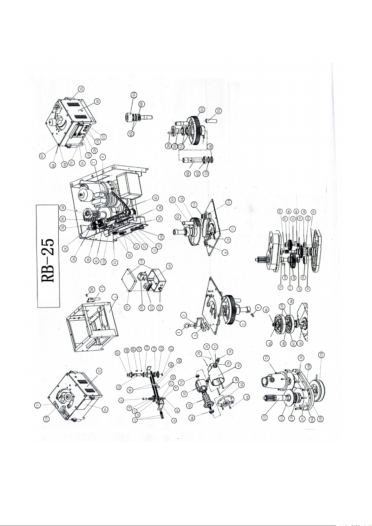
RB-25 PARTS LIST
NO.
PARTS NAME
NO.
PARTS NAME
NO.
PARTS NAME
1
Foot stand sets
44
stop film
87
6202 bearing15×35×11
2
work table sets
45
chain connector
88
gear
3
fixed gasket
46
cup head rivetΦ3.5×4
89
round head flat key
4
hexagonal screw
47
shaft circlip Φ20
90
6302bearing15×42×13
5
adjust block
48
round head flat key
91
gear shaft
6
model
49
right shutter
92
61910 bearing 50×72×12
7
locating shaft
50
chain wheel
93
10008bearing40×68×9
8
hexagon socket set
51
chain wheel shaft
94
6004bearing20×42×12
9
buffer block
52
round head flat key
95
stop washer 16
10
stop block
53
chain wheel
96
round nut M16×1.5
11
hexagon socket set
54
inner hexagon screw
97
round head flat key
12
chain wheel
55
leakage terminal welding
98
Needle bearing
13
pin roll
56
round nut M45×1.5
99
bearing gasket
14
gasket 12
57
stop washer Φ45
100
gear shaft
15
nut M12
58
round head flat
101
inner hexagon screw
16
chain wheel foot stand
59
locating sleeve
102
connecting gear
17
61901bearing12×24×6
60
connect sleeve
103
6305 bearing25×62×17
18
hexagon headed bolt
61
6011 bearing 55×90×18
104
gear case(up case)
19
round pin 10×35
62
6009 bearing 45×75×16
105
gear case(down case)
20
inner hexagon
63
big gear component
106
inner hexagon screw
21
cord arma
64
roll wheel
107
washer
22
cord arma
65
6207 bearing 35×72×17
108
gear
23
electrical housing
66
hole collar Φ72
109
round head flat key
24
gasket
67
chamfer head screw
110
6208bearing40×80×18
25
pan head screw M4×7
68
spring washerΦ10
111
washer
26
Down sensor holder
69
nut M10
112
housing
27
nut M4
70
air door plate
113
gear shaft
28
chamfer head screw
71
handle rivet sets
114
washer
29
nut bolt
72
6303 bearing 17×47×14
115
6204bearing20×47×14
30
nut M5
73
inner hexagon screw
116
gasket
31
up sensor holder
74
6200bearing 10×30×9
117
inner hexagon screw
32
cord holder
75
carbon holder's washer
118
6004 bearing
33
hand wheel
76
hexagon socket set
119
electric box
34
panel
77
carbon holder sets
120
contactor
35
pan head screw
78
carbon holder cap
121
relay
36
inner hexagon screw
79
carbon brush sets
122
water joint
37
left shutter
80
inner hexagon screw
123
sensor
38
tension spring holder
81
Motor housing
124
navitage plug
39
tension spring
82
stator components
125
indicator lamp
40
splitpinΦ3.2×16
83
rotor components
126
jogging switch
41
tension spring holder
84
inner hexagon screw
127
emergency switch
42
chain 08B-1-35
85
motor end housing
128
magnetic clutch
43
chain 06B-1-T6
86
6203 bearing 17×40×12
129 PC Board 130 limited switch
17

18
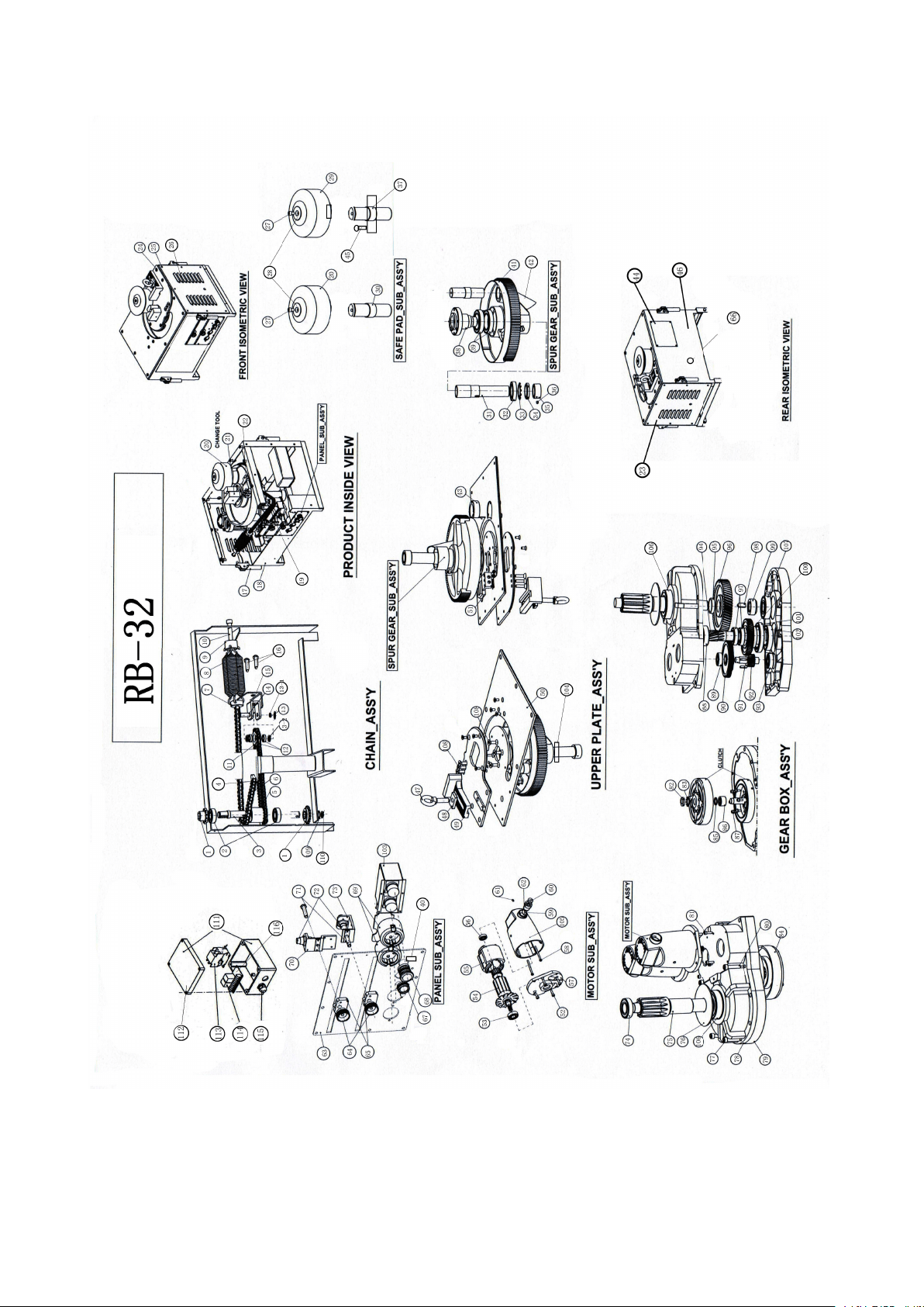
RB-32 PARTS LIST
NO
PARTS NAME
NO
PARTS NAME
NO
PARTS NAME
1
connecting chain
40
ON-OFF switch
79
gear case (down case)
2
bearing 6902 28×15×7
41
big gear component
80
hexagon socket set
3
chain shaft
42
leakage terminal pipe
81
inner hexagon M6×25
4
chain connector
43
bearing housing
82
nut
5
chain 3
44
small air door plate
83
gasket
6
chain 4
45
inner hexagon M12×12
84
magnetic clutch
7
tension spring holder
46
foot stand sets
85
gasket
8
tension spring
47
Ring Screw M18×55
86
needle bearing
9
tension spring holder
48
fixed gasket
87
inner hexagon
10
outer hexagon M10×40
49
adjust block
88
6305 bearing
11
chain wheel
50
work table
89
6203 bearing 40×17×12
12
6002bearing32×15×9
51
stock block
90
gear
13
nut M12
52
hexagon socket set
91
pin
14
chain pin
53
6203 bearing 40×17×12
92
bearing shaft
15
chain wheel foot stand
54
rotor components
93
6204bearing
16
hexagon socket set
55
stator components
94
gear shaft
17
handle sets
56
bearing 6200 30×10×9
95
stop washer¢20
18
housing
57
motor end housing
96
gear
19
round pin¢10×40
58
inner hexagon M5×70
97
6006bearing 65×30×13
20
idler wheel
59
carbon brush
98
pin
21
module
60
brush holder cap
99
gasket
22
buffer block
61
hexagon socket set
100
connecting gear
23
left shutter
62
brush holder
101
6913 bearing 90×65×13
24
hexagon chamfer screw
63
panel
102
6306bearing 72×30×19
25
cup head screw M5×8
64
hand wheel
103
electric housing
26
right shutter
65
cord holder
104
limited switch
27
inner hexagon M12×15
66
back emergency switch
105
motor housing
28
gasket
67
Micro switch
106
6308bearing 90×40×23
29
locating sleeve
68
emergency switch
107
6009bearing 75×45×16
30
idler wheel shaft
69
Aviation plug
108
hexagon chamfer screw
31
connecting sleeve
70
up sensor holder
109
spring washer
32
bearing6011 90×55×18
71
screw
110
M12
33
stop washer¢20
72
sensor
111
electric box
34
round nut M55×2
73
down sensor holder
112
electrical housing
35
locating ring
74
bearing 6206 62×30×16
113
contactor
36
hexagon socket set
75
main gear shaft
114
relay
37
locating shaft
76
gear box cover
115
water joint
38
locating sleeve
77
inner hexagon M10*40
116
PC board
39
bearing6014
78
gear case(up case)
19

20
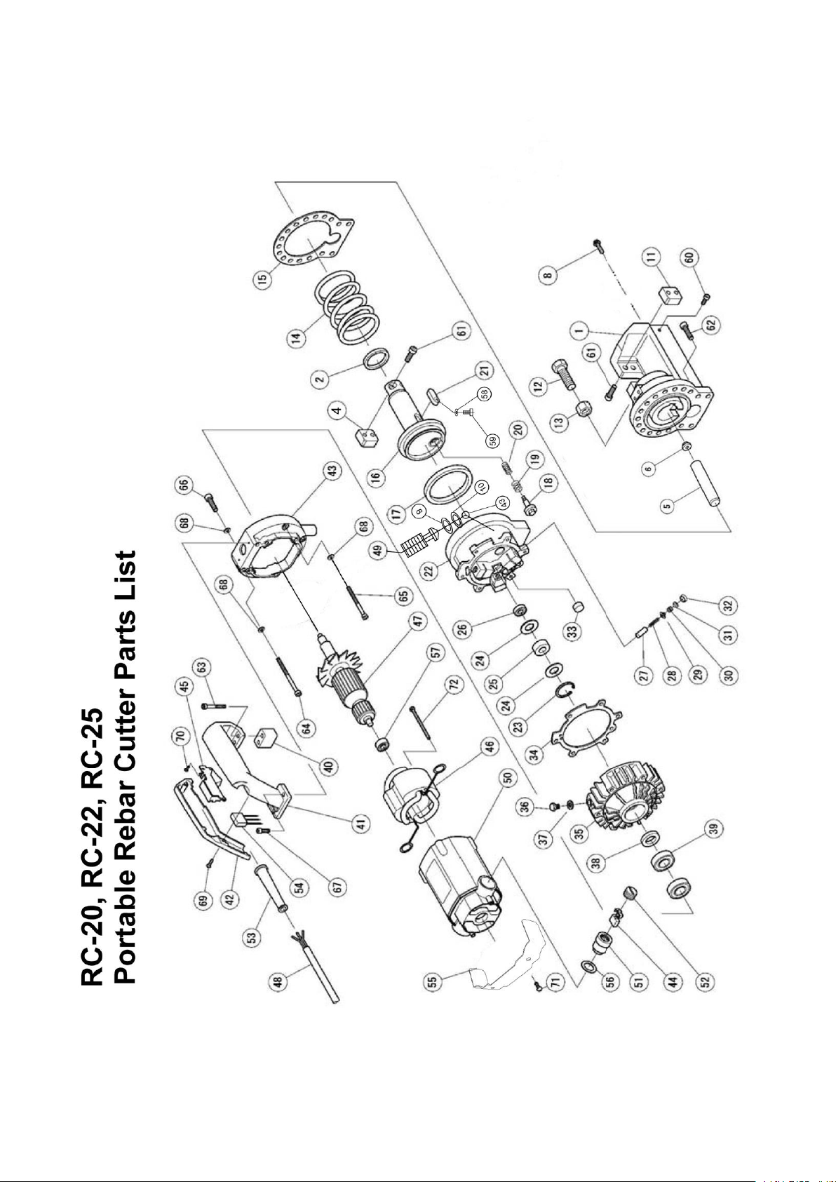
RC-25 PARTS LIST
NO.
PARTS NAME
NO.
PARTS NAME
1
CUTTER HEAD
40
CONNECTING BLOCK
2
GASKET RING 40×50×6
41
HANDLE
3
**
42
HANDLE COVER
4
CUTTER BLOCK / BLADE
43
PHOTOSPHERE Ф4.763
5
AIR BAG
44
CARBON BRUSH
6
NUT
45
SWITCH
7
**
46
STATOR COIL
8
SCREW
47
ARMATURE
9
O RING
48
ELECTRICAL CORD
10
O RING
49
BOLT
11
CUTTER BLOCK / BLADE
50
MOTOR HOUSING
12
HEXAGONAL SCREW
51
CARBON BRUSH HOLDER
13
NUT
52
CARBON BRUSH CAP
14
BIG SPRING
53
CABLE ARMOR
15
GASKET
54
**
16
CUTTER ROD
55
**
17
GASKET RING 80×95×9
56
GUM WASHER
18
RETURN SHAFT
57
BEARING 6200
19
SPRING
58
WAVE WASHER
20
SPRING
59
BOLT M4*8
21
PIN 12×40
60
BOLT M8*25
22
CYLINDER
61
BOLT M8*30
23
SNAP RING
62
BOLT M8*30
24
MANGANESE STEEL GASKET
63
BOLT M6*20
25
NEEDLE BEARING 14×30×12
64
BOLT M6*20
26
BEARING 609
65
BOLT M6*25
27
PISTON
66
BOLT M6*50
28
SPRING
67
BOLT M6*20
29
OIL VALVE
68
WASHER
30
SPRING
69
BOLT M4*12
31
SPRING GUIDE
70
BOLT M4*8
32
OIL SEAL
71
**
33
FILTER MAGNET
72
BOLT M5*75
34
GASKET
73
CONNECTING PLATE
35
PUMP CASE
36
HEXAGONAL SCREW M10×16
37
COMPOUND GASKET Ф10
38
OIL SEAL 20×35×8
39
BEARING 104
21

22
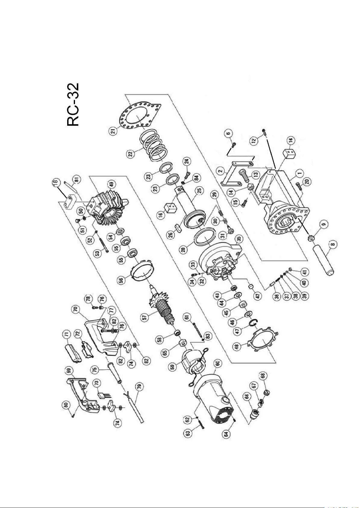
RC-32 PARTS LIST
NO.
PARTS NAME
NO.
PARTS NAME
NO.
PARTS NAME
1
HOUSING
28
SEAL 85X100X9
55
BEARING 6004
2
SUB HANDLE
29
RETURN SPRING UP
56
FAN COVER
3
COLLAR
30
RETURN SPRING
57
ARMATURE
4
P. WASHER
31
RETURN VALVE
58
BEARING 6200
5
S .WASHER
32
STEEL BALL
59
STATOR COIL
6
CAP BOLT M8X16
33
O RING
60
MOTOR HOUSING
7
SEAL 26X32X4
34
RELEASE VALVE
61
TAPPING SCREW
8
AIR BAG
35
CYLINDER
62
P.WASHER M6
9
TIGHT SCREW
36
PISTON
63
CAP BOLT M6X25
10
**
37
SPRING
64
CAP BOLT M5X16
11
**
38
DELIVERY VALVE
65
**
12
SCREW
39
SPRING
66
BRUSH HOLDER
13
BOLT M16X40
40
SPRING GUIDE
67
CARBON BRUSH
14
NUT M16
41
PUMP HEAD SEAL
68
BRUSH CAP
15
CAP BOLT M8X30
42
MAGNET FILTER
69
HANDLE COVER
16
CUTTER BLOCK
43
BEARING 609
70
HANDLE
17
CAP BOLT
44
BEARING GUID
71
SWITCH SUPPORT
18
**
45
NEEDLE BEARING
72
SWITCH
19
CAP BOLT M6X20
46
BEARING GUIDE
73
CONDENSER
20
CAP BOLT M10X40
47
SNAP RING
74
HANDLE STAY
21
CYLINDER PACKING
48
PUMP CASE PACKING
75
CORD ARMOR
22
RETURN SPRING
49
PUMP CASE
76
P.WASHER M6
23
SEAL 45X55X6
50
SEAL WASHER
77
CAP BOLT M6X35
24
CAP BOLT M8X25
51
CAP BOLT M10X16
78
CAP BOLT M6X35
25
CUTTER ROD
52
SEAL WASHER
79
CORD
26
PIN 12X40
53
CAP BOLTM6X50
80
TAPPING SCREW
27
**
54
OIL SEAL 20X35X8
81 TAPPING SCREW 82 WASHER