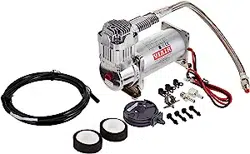
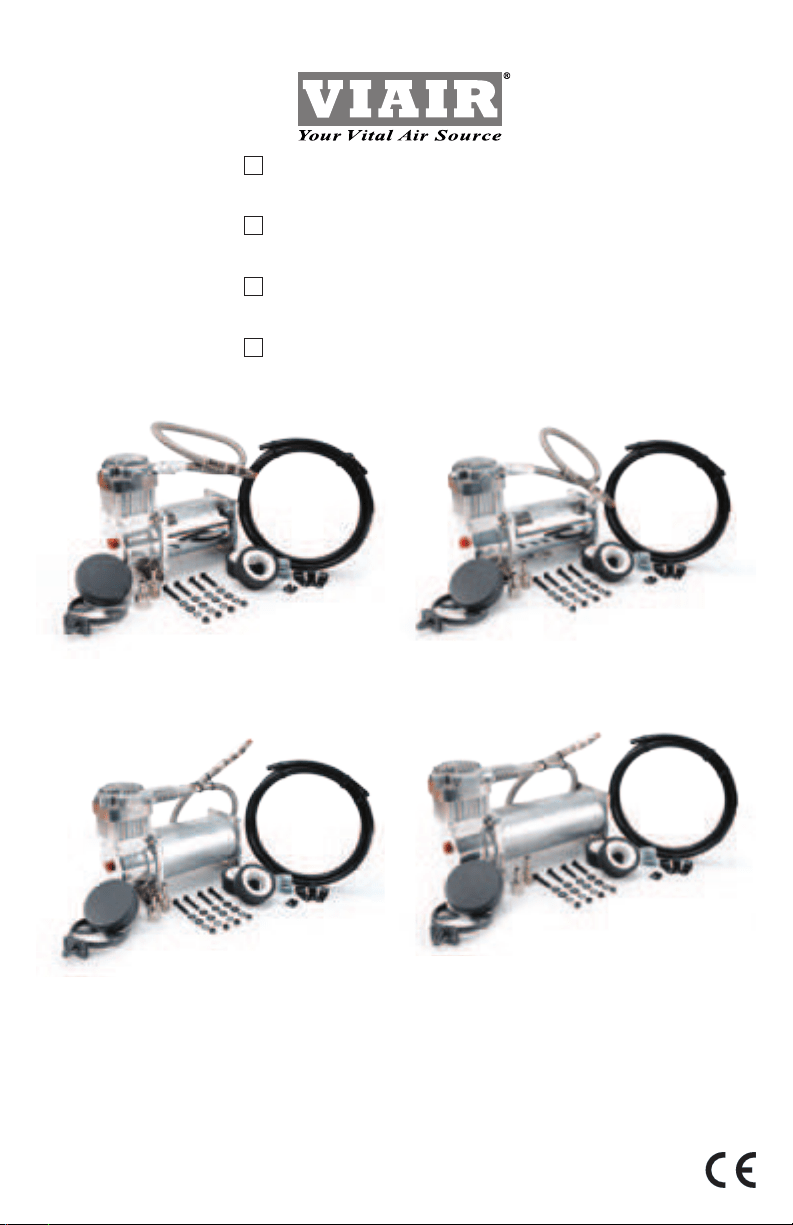
325C AIR COMPRESSOR KIT
PART NO. 32530 - 32533 - 32534 - 32538
350C AIR COMPRESSOR KIT
PART NO. 35030 - 35033
400C AIR COMPRESSOR KIT
PART NO. 40040
450C AIR COMPRESSOR KIT
PART NO. 45040
IMPORTANT:
It is essential that you and any other operator of this
product read and understand the contents of this manual
before installing and using this product.
SAVE THIS MANUAL FOR FUTURE REFERENCE
USER MANUAL
325C 350C
400C 450C

IMPORTANT SAFETY INSTRUCTIONS
CAUTION - To reduce risk of electrical shock:
- Donotdisassemble.Donotattemptrepairsormodications.Refertoqualiedserviceagencies
forallserviceandrepairs.
- Donotusethisproductinanareawhereitcanfallorbepulledintowaterorotherliquids.
- Donotreachforthisproductifithasfallenintoliquid.
- Usethiscompressorwith12-voltor24-volt(P/N32538)DCsystemsonly.
- Thisproductshouldneverbeleftunattendedduringuse.
WARNING - To prevent injury:
- Neverallowchildrentooperatethiscompressor.Closesupervisionisnecessarywhenthiscompressor
is being used near children.
- ThiscompressorwillbecomeveryHOTduringandimmediatelyafteruse.Donottouchanypartofthis
compressor with bare hands during and immediately after use.
- Donotusethisproductnearamesorexplosivematerialsorwhereaerosolproductsarebeingused.
- Donotoperatethisproductwhereoxygenisbeingadministered.
- Do not pump anything other than atmospheric air.
- Neverusethisproductwhilesleepyordrowsy.
- Donotuseanytoolsorattachmentswithoutrstdeterminingmaximumairpressureforthattool
or attachment.
- Neverpointanyairnozzleorairsprayertowardanotherpersonoranypartofthebody.
- ThisaircompressorisequippedwithanAutomaticResetThermalProtector,andcanautomatically
restartafterthethermalprotectorresets.Alwayscutoffpowersourcewhenthermalprotector
becomesactivated.
- Wear safety glasses or goggles when operating this product.
- Useonlyinwellventilatedareas.
INSTALLATION
Pleasereadandfollowtheinstallationinstructionscarefullytoavoidinjuryordamagetothe
compressorandyourvehicle.
Eachofouraircompressorsandpartshavebeencarefullyproducedandpackaged.Beforeyou
begininstallation,pleasefamiliarizeyourselfwithInstallationPartsList(Fig.1)ofthismanual.
Guidelines for Selecting Mounting Location:
The selection of proper mounting location for your air compressor will help ensure a long and trouble
freecompressorservicelife.Pleasepay close attention to the following guidelines:
1. Select a FLAT,UPRIGHTANDSECURE location where the compressor can be mounted.
2.Tomaximizeaircompressorperformance,locatecompressorasCLOSETOTHEBATTERY as
possiblesothatlengthofpositiveleadwirerequiredisataminimum.
3. Choose mounting location that is as cool as possible and AWAYFROMHEATSOURCES.
Thecoolertheambienttemperature,thelesschancethecompressorwilloverheat.
4.Thiscompressorismoisture&dustresistant,butNOTDIRTORWATERPROOF. Do not mount
compressor in locations where the unit is likely to come in contact with the elements.
5.Forcompressorwithremoteltermounting,selectcompressor’smountinglocationwhereairline
canberoutedfromcompressorairinlettoremoteinletairlter.Makesurethattheremoteinletair
lterislocatedinadrylocation,awayfromtheelements.
6.Youwillalsowanttoselectacompressormountinglocationwheretheleaderhosebracketcanbe
mounted to leader hose. (Not applicable to P/N 32534)
7.Ifitisnecessarytomounttheaircompressorfurtherawayfromthebattery,suchasinside
yourvehicleorinthebedofyourpickup,useapositiveleadwireforremoteinstallation.Referto
the wire gauge guide on the back of this manual.
8.Donotmountcompressornearareaswhereammableliquidsarestored.
9.Usethreadsealantforproperttinginstallation.Teontapeisnotrecommended.
Properlysealed,recommendedtorqueis12to15ft.lbs
USER MANUAL
325C - 350C - 400C - 450C COMPRESSOR KIT
MOUNTING AND WIRING
1. Disconnectgroundcablefromvehicle’sbattery.
2. Temporarily position the air compressor in the location where it will be mounted.
3. Routegroundwiretothenegativepostofthebatteryortoanappropriategroundingpointand
cut ground wire to length as needed.
4. Mountaircompressorwiththefoursetsofbolts,nuts,washers,andlockingwashersprovided.
(SeeFig.2forMountingInstructions)Useofthreadsealantrecommended.
5. NOTE:Forremoteinletairlterinstallation,refertoinstructionsincludedintheRemoteInletAir
FilterPack.
6. Thisaircompressormaybeequippedwithaheavydutyheatresistantleaderhose.Thisleader
hoseisdesignedtoprolongthelifeofyourairline.Donotremovethisleaderhosefromair
compressor. (Not applicable to P/N 32534)
7. IMPORTANT:Pleasenote,theleaderhosethatmaybeequippedwithyourcompressormay
alsohaveabuilt-ininlinecheckvalve.Donotremoveinlinecheckvalvefromleaderhoseif
soequipped.
8. Selectaproperlocationtomountleaderhosewithhosebracketprovided.Avoidlocations
where leader hose may become tangled with wires and other hoses.
9. Tomounthosebracket,drillholewith3/16”drillbitandpushself–anchoringhosebracketpin
intohole.Routeleaderhosethroughhosebracketandsecurehosebypressingbracketclamp
into locked position.
10.Toremovehosefromthehosebracket,simplypressdownonthehoseclampreleasetabto
releasebracketclamp.(Fig.3)
11.Connectcompressor’spositiveleadwiretooneoftheleadsofyourpressureswitch.
12.Makesurethatyourcompressorsetupisproperlyfused.Forappropriatefusesize,refertoamp
drawofcompressorinthespecicationssectionofthismanual.
13.Alwayslocatefuseascloseaspossibletopowersource.
14.Beforeconnectingtopowersource,re-checktomakesurethatallconnectionsare
made properly.
15. Connect and test compressor system by running the compressor for a short time to build up
pressure in your air tank.
16.Onceairpressurereachespresetcutoutpressureofyourpressureswitch,thecompressorwill
shut off. Inspect all air line connections for leaks with soap and water solution. If a leak is
detected,theairlinemaynotbecutsquarelyorpushedallthewayin.
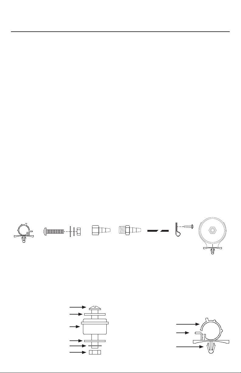
(Fig. 1) 325C / 350C / 400C / 450C Compressor Installation Parts List:
A.HoseBracket(1pc) - N/A 32534
B.MountingBolts(4pcs)
C.FlatWashers(8pcs)
D.LockingWashers(4pcs)
E.Nuts(4pcs)
F.1/4”NPTFx3/8”BarbedFitting(1pc)
G.1/4”NPTMx3/8”BarbedFitting(1pc)
H.3/8”AirLine
I.AirLineClips(3pcs)
J.Screws(3pcs)
K.RemoteInletAirFilterwithFilterElement(1pc)
(Fig. 2) Compressor
Mounting Hardware
B.MountingBolt
C.FlatWasher
D.LockingWasher
E.Nut
K. Vibration Isolator
USER MANUAL
325C - 350C - 400C - 450C COMPRESSOR KIT
REDUCER
B
A
C D E
F
G
I
J
K
(Fig. 3) Leader Hose Bracket (N/A 32534)
L.HoseClamp
M.ClampReleaseTab
N.Self-AnchoringPin
B
C
C
D
E
K
REDUCER
L
M
N
H
OPERATING INSTRUCTIONS
1. IMPORTANT:AlwaysoperatethecompressoratorbelowtheMAXIMUMPRESSURERATINGof
thecompressor.PleaserefertoApplication&SpecicationsSectionsofthismanualfordetails.
2.AlwaysobservetheMAXIMUMDUTYCYCLEoftheaircompressor.RefertoCompressor
ApplicationsandSpecicationsSectionsofthismanualfordetails.Operationexceeding
maximumpressureratingsand/ordutycyclewillresultindamagetotheaircompressor.
3.YouraircompressorisequippedwithanAUTOMATICTHERMALOVERLOADPROTECTOR.This
featureisdesignedtoprotecttheaircompressorfromoverheatingandcausingpermanent
damagetoyouraircompressor.Thethermaloverloadprotectorwillautomaticallycutpowerto
youraircompressorshouldtheinternaloperatingtemperatureoftheaircompressorriseabove
safelevelsduringexcessiveuse.
4.Shouldatanytimeduringuse,youraircompressorautomaticallyshutsoff;donotattemptto
restart it. Turn off power and allow unit to cool for about 30 minutes. This will allow the Thermal
OverloadProtectortoresetsoyoucansafelyresumeuseoftheaircompressor.
5.Topreventdischargeofyourvehicle’sbattery,andenhanceperformance,keepthevehicle’s
engine running while using the compressor.
6.Onlyoperatecompressorinwellventilatedareas.
7.Theuseofarelayisstronglyrecommendedforinstallationofthiscompressor,butnotincluded.
(40-amprelayvalueorhigherpercompressorrecommended).
MAINTENANCE & REPAIRS
1.Periodicallycheckallelectricalandttingsconnections.Cleanandtightenasneeded.
2.Periodicallycheckallmountingscrews.Tightenasneeded.
3.ReplaceAirFilterElementperiodically.Replacementfrequencydependsonoperatingfrequencyand
operatingenvironment.Forfrequentuseindustyenvironment,werecommendthatyoureplaceair
lterelementatleastonceamonth.
4.Regularlycleandustanddirtfromcompressorcoolingnsandmotorhousing.
5.Youraircompressorisequippedwithapermanentlylubricated,maintenance-freemotor.Nevertryto
lubricate the compressor.
6.AllrepairsshouldbeperformedbyManufacturerorManufacturer’sAuthorizedServiceAgenciesonly.
CAUTION:
Nevertouchtheaircompressororttingsconnectedtotheaircompressor,withbarehandsduring
orimmediatelyafteruse.Theleaderhoseandttingsconnectedtoleaderhosewillbecomevery
HOTduringandafteruse.Ifnecessary,wearheatresistantglovestohandlettings,airline,and
leader hose.
USER MANUAL
325C - 350C - 400C - 450C COMPRESSOR KIT
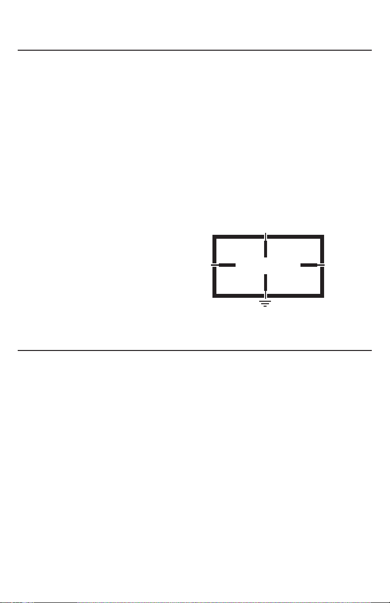
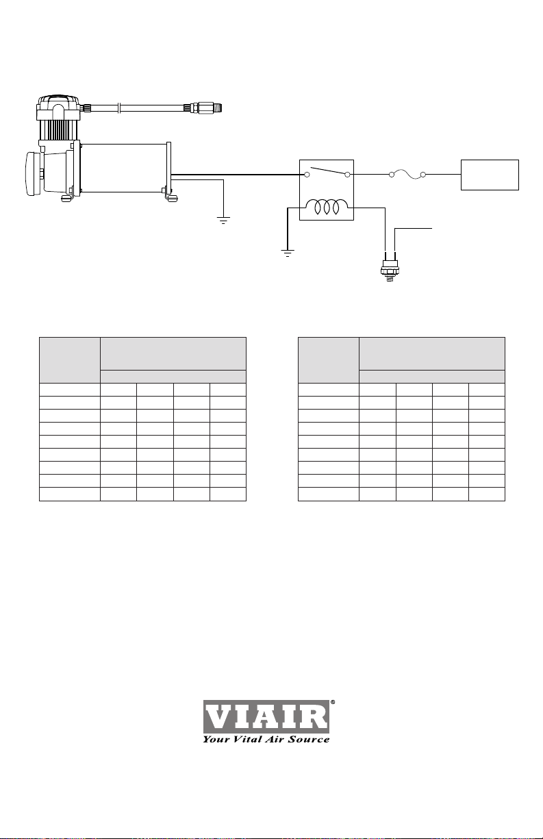
RELAY WIRING SCHEMATIC
Pressure Switch
86
Fused
12-Volt
30
To Ground
85
87
Compressor
(+) Lead

SPECIFICATIONS
•PartNo.32530/32533/32534/32538/325CAirCompressorKit/Silver&Chrome(CESpec.)
MotorVoltage: 12volts
24volts(32538)
Max.CurrentConsumption: 21amps-12v
13amps-24v
MotorType: PermanentMagnetic
Horsepower: 1/4
Max.WorkingPressure: 150PSI
Max.DutyCycle(@72ºF&100PSI): 33%
MinutesOn/Off(@72ºF&100PSI): 20On/40Off
Max.RestartPressure: 200PSI
Max.AmbientTemperature: 158°F
Min.AmbientTemperature: -40°F
Auto.ResetThermalProtection: Yes
Dimensions: 8”Lx4”Wx6.75H”
NetWeight: 7.50Lbs.
•PartNo.35030&35033/350CAirCompressorKit/Silver&Chrome(CESpec.)
MotorVoltage: 12Volts
Max.CurrentConsumption: 20Amps
MotorType: PermanentMagnetic
Horsepower: 1/4
Max.WorkingPressure: 150PSI
Max.DutyCycle(@72°F&100PSI): 100%
MinutesOn/Off(@72°F&100PSI): 1HourRunTime
Max.RestartPressure: 200PSI
Max.AmbientTemperature: 158°F
Min.AmbientTemperature: -40°F
Auto.ResetThermalProtection: Yes
Dimensions: 9”Lx4”Wx6.75H”
NetWeight: 8.55Lbs.
•PartNo.40040/400CAirCompressorKit/Silver(CESpec.)
MotorVoltage: 12Volts
Max.CurrentConsumption: 28Amps
MotorType: PermanentMagnetic
Horsepower: 1/4
Max.WorkingPressure: 150PSI
Max.DutyCycle(@72°F&100PSI): 33%
MinutesOn/Off(@72°F&100PSI): 20On/40Off
Max.RestartPressure: 200PSI
Max.AmbientTemperature: 158°F
Min.AmbientTemperature: -40°F
Auto.ResetThermalProtection: Yes
Dimensions: 9”Lx4”Wx6.75H”
NetWeight: 8.65Lbs.
•PartNo.45040/450CAirCompressorKit/Silver(CESpec.)
MotorVoltage: 12Volts
Max.CurrentConsumption: 23Amps
MotorType: PermanentMagnetic
Horsepower: 1/4
Max.WorkingPressure: 150PSI
Max.DutyCycle(@72°F&100PSI): 100%
MinutesOn/Off(@72°F&100PSI): 1HourRunTime
Max.RestartPressure: 200PSI
Max.AmbientTemperature: 158°F
Min.AmbientTemperature: -40°F
Auto.ResetThermalProtection: Yes
Dimensions: 10.6”Lx4”Wx6.87H”
NetWeight: 10.80Lbs.
USER MANUAL
325C - 350C - 400C - 450C COMPRESSOR KIT

COMPRESSOR APPLICATION GUIDE
Toensurethatyougetthehighestlevelofsatisfactionfromyourcompressor’sperformance,referto
information below:
VIAIR COMPRESSOR REFERENCE CHART
COMPRESSORSERIES DUTYCYCLE MAX.WORKINGPRESSURE
(100PSI@72°F)
090SERIES 9% 120PSI
092SERIES 9% 120PSI
095SERIES 9% 120PSI
097SERIES 10% 130PSI
098SERIES 10% 130PSI
100SERIES 15% 130PSI
250IGSERIES 100% 150PSI
275SERIES 25% 150PSI
280SERIES 30% 150PSI
325SERIES 33% 150PSI
330IGSERIES 100% 150PSI
350SERIES 100% 150PSI
380SERIES 100% 200PSI
*55%
400SERIES 33% 150PSI
420SERIES 33% 150PSI
444SERIES 100% 200PSI
*50%
450SERIES 100% 150PSI
450IGSERIES 100% 150PSI
460SERIES 100% 150PSI
480SERIES 100% 200PSI
*50%
*Duty Cycle at 200 PSI and 72°F.
ABOUT COMPRESSOR DUTY CYCLE:
Dutycyclereferstotheamountoftimeacompressorcanbeoperatedinagiventimeperiodat100
PSI,andastandardambienttemperatureof72°F.Itiscommonlyexpressedinpercentageformat:
Compressorontime÷(ontime+offtime)=DutyCycle%.
ONE-HOUR DUTY CYCLE MINUTES ON /
(100PSI@72°F) MINUTES OFF
9% 5Min.On/55Min.Off
10% 6Min.On/54Min.Off
15% 9Min.On/51Min.Off
20% 12Min.On/48Min.Off
25% 15Min.On/45Min.Off
30% 18Min.On/42Min.Off
33% 20Min.On/40Min.Off
50% 30Min.On/30Min.Off
100% 1HourRunTime
NOTE:Allcompressors,regardlessofrateddutycycle,requiresufcientresttimeinbetweencycles
toallowforpartialorcompleteheatdissipation.Heatdissipationratesmayvarydependingon
ambient temperatures and operating conditions.
ABOUT RATED WORKING PRESSURE:
Toensuretroublefreeservicelifeofyourcompressor,alwaysoperatecompressorwithinrated
workingpressureofthecompressor.Neveruseapressureswitchwithahighercut-offpressure
thancompressor’sratedworkingpressure.
USER MANUAL
325C - 350C - 400C - 450C COMPRESSOR KIT

325C - 350C - 400C - 450C COMPRESSOR KIT
TROUBLESHOOTING GUIDE:
Tank pressure drops when
compressor(s)shutoff
1.Loosedraincock
2.Checkvalveleaking
3.Looseconnections
1. Tighten drain cock
2.Replacecheckvalveor
compressor
3. Check all connections with
soap and water solution
and tighten
Compressor runs
continuouslyandairow
lower than normal
1.Excessiveairusage
2.Looseconnections
3. Worn piston ring or inlet
valve.
4.Cloggedairlterelement
1. Decrease air usage
2. Check all connections with
soap and water solution
and tighten.
3.Replacecompressor
4.Replaceairlterelement
Compressor runs
continuously causing
safetyvalve(ifequipped)
to open
1.Faultypressureswitch
2.Defectivesafetyvalve
1.Replacepressureswitch
2.Replacesafetyvalve
Excessivemoisturein
discharge
1.Excessivewaterinairtank
2.Highhumidity
1.Draintank,tilttanktodrain.
Draintankmorefrequently
2.Movecompressortoarea
withlesshumidity,oruse
airlinelter
Compressor will not run 1.Nopower,orpowerswitch
inOFFposition
2.Blownfuse
3.Motoroverheats
4.Faultypressureswitch
(ifhookeduptoa
pressureswitch).
1.Makesurecompressor
switchisON
2. Disconnect compressor
frompowersource,replace
fuse.(RefertoSpecications
section for correct
fuseamperage)
3.Letcompressorcoolofffor
about 30 minutes to allow
thermaloverloadswitchtoreset.
4.Replacepressureswitch
Thermaloverload
protector cuts out
repeatedly
1.Lackofproperventilationor
ambient temperature is too high
2.Compressorvalvesfailed
1.Movecompressortowell
ventilatedarea,orareawith
lower ambient temperature
2.Replacecompressor
Excessiveknocking
or rattling
1.Loosemountingbolts
2. Worn bearing on eccentric or
motor shaft
3. Cylinder or piston ring is worn
1. Tighten bolts
2.Replacebearingor
piston assembly
3.Replacepistonorcompressor
CAUTION: NEVER DISASSEMBLE COMPRESSOR WHILE
COMPRESSOR IS PRESSURIZED.
USER MANUAL
PROBLEM: POSSIBLECAUSE(S) CORRECTIVEACTION
USER MANUAL
325C - 350C - 400C - 450C COMPRESSOR KIT
Wiring Diagram:
(Fuse Not Included)
SINGLE “C” MODEL
COMPRESSOR WIRING DIAGRAM
15 Edelman
Irvine, CA 92618
949-585-0011
www.viaircorp.com
87
86
30
85
+
-
Battery
To Keyed
Power Source
40A Relay
Fuse
Pressure
Switch
Rev.1
325C, 350C @ 30A
400C, 450C @ 40A
AMERICAN WIRE GAUGE GUIDE 12-VOLT: AMERICAN WIRE GAUGE GUIDE 24-VOLT:
AmpDraw
Lengthofwirefrombatteryto
compressor(infeet)
5 10 15 20
5 16 16 16 14
10 16 14 12 10
15 16 12 10 10
20 14 10 10 8
25 14 10 8 6
30 12 10 8 6
40 12 8 6 6
50 10 6 6 4
60 10 6 4 4
AmpDraw
Lengthofwirefrombatteryto
compressor(infeet)
5 10 15 20
5 16 16 16 16
10 16 16 16 14
15 16 16 14 12
20 16 14 12 10
25 16 12 12 10
30 16 12 10 10
40 14 10 10 8
50 14 10 8 6
60 12 10 8 6
LIMITED WARRANTY:
VIAIRCorporationwarrantsthisproduct,whenproperlyinstalledandundernormalconditionsof
use,tobefreefromdefectsinworkmanshipandmaterialsforaperiodofoneyearfromitsoriginal
dateofpurchase.Toreceivewarrantyserviceorrepair,pleasecontactVIAIRCorporation.
Returnsshouldbemadewithinoneyearofthedateofpurchase,afteraReturnGoodsAuthorization
(RGA)numberhasbeenassignedbyVIAIRCorporation.ToobtainRGA,faxacopyofyourreceipt
to(949)585-0188.Forcompletewarrantydetails,pleasevisit:www.viaircorp.com/warranty
PLEASE NOTE:
THISWARRANTYCOVERSPRODUCTDEFECTSONLY;ITDOESNOTCOVERINCIDENTAL
ORCONSEQUENTIALDAMAGESASRESULTOFMISUSEORABUSE.
15EDELMAN•IRVINE,CA92618
TEL:(949)585-0011•FAX:(949)585-0188
www.viaircorp.com
