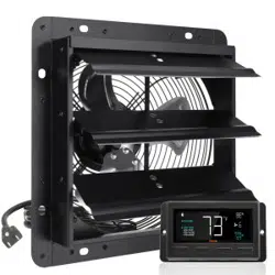

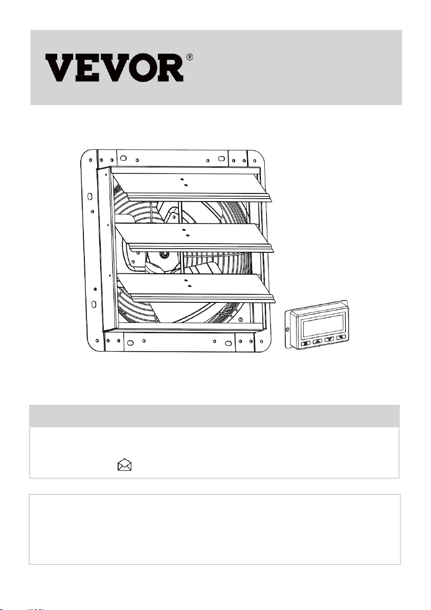
SHUTTER EXHAUST FAN
USER MANUAL
We continue to be committed to provide you tools with competitive price.
"Save Half", "Half Price" or any other similar expressions used by us only
represents an estimate of savings you might benefit from buying certain tools
with us compared to the major top brands and doses not necessarily mean to
cover all categories of tools offered by us. You are kindly reminded to verify
carefully when you are placing an order with us if you are actually saving half
in comparison with the top major brands.

- 1 -
Have product questions? Need technical support? Please feel free to
contact us:
CustomerService@vevor.com
NEED HELP? CONTACT US!
This is the original instruction, please read all manual instructions
carefully before operating. VEVOR reserves a clear interpretation of our
user manual. The appearance of the product shall be subject to the
product you received. Please forgive us that we won't inform you again if
there are any technology or software updates on our product.
<Picture Only For Reference>
SHUTTER EXHAUST FAN
USER MANUAL
- 2 -
PLEASE READ THE INSTRUCTIONS CAREFULLY BEFORE
USING THE EQUIPMENT
Contents
Ⅰ
.SAFETY PRECAUTIONS
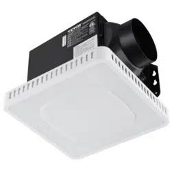
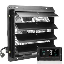
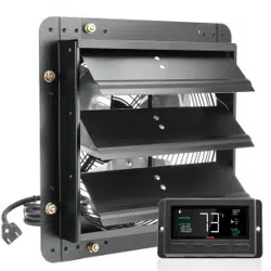
Ⅱ.PRODUCT DESCRIPTION
Ⅲ.INSTALLATION
Ⅳ.POWERING AND SETUP
Ⅴ
.CLEANING
Ⅵ
.PROGRAMMING
SAFETY PRECAUTIONS
WARNING Read all safety warnings, instructions,
illustrations and specifications provided with this electrical
appliances. Failure to follow all instructions listed below may
result in electric shock, fire and/or serious injury.
Save all warnings and instructions for future reference.
WARNING
Improper operation may cause personal injury.
Improper operation may cause damage to the
machine.
Improper operation may cause others object
damage.
The symbol indicates that the user should pay
high attention to and pay attention to the drawing
shows the situation to be noted, and the left figure
shows "Be careful of electric shock"
Disconnect the fan when moving from one
location to another.
Do not use a power supply that does not meet the
rated voltage
The use of non compliant power supplies can
cause fire or electric shock. If the supply cord is
damaged, it must be replaced by the
manufacturer, its service agent or similarly
qualified persons in order to avoid a hazard.
- 3 -
If the machine emits smoke, odor, motor noise
and other abnormal conditions,Please do not use
it. It may cause fire or electric shock
Do not disassemble, repair or rectify the machine
during use.
Doing so may result in fire or electric shock and
personal injury
BE CAREFUL
DO NOT use fan in window. Rain may create
electrical hazard.
Do not damage or arbitrarily change the original
power cord, and do not bend, forcibly pull, bind or
press the power cord under heavy objects.This
will damage the power cord, causing electric
leakage fire or electric shock
If the machine is not used for a long time, please
unplug the power cord from the socket
The connection socket must be installed with
leakage protection switch device
Never insert fingers, pencils, or any other object
through the guard when fan is running.
When the power cord is unplugged from the
socket, the plug should be unplugged. Do
not pull the power cord to forcibly pull the
wire, which may cause damage to the wire
and lead to leakage or electric shock
- 4 -
Disconnect the fan when removing grills for
cleaning.Do not leave the fan running
unattended. This appliance can be used by
children aged from 8 years and above and
persons with reduced physical, sensory or mental
capabilities or lack of experience and knowledge
if they have been given supervision or instruction
concerning use of the appliance in a safe way
and understand the hazards involved. Children
shall not play with the appliance. Cleaning and
user maintenance shall not be made by children
without
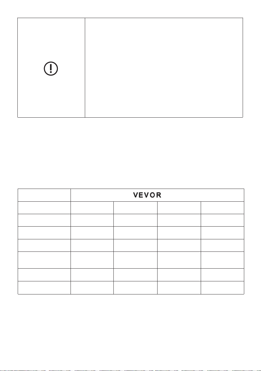
PRODUCT DESCRIPTION
TECHNICAL PARAMETER
Brand
Model
BT-WL10A
BT-WL12A
BT-WL14A
BT-WL16A
Voltage
120 V
120 V
120 V
120 V
Frequency
60 Hz
60 Hz
60 Hz
60 Hz
Power
25 W
40 W
45 W
55 W
Pack
Size(CM)
34.5*34.5*22
40.5*40.5*23.5
45.5*23.3*45.5
50.5*23.8*50.5
N. W
2.7 KG
4.1 KG
4.6 KG
6.0 KG
G. W
3.45 KG
4.5 KG
5.5KG
6.7 KG
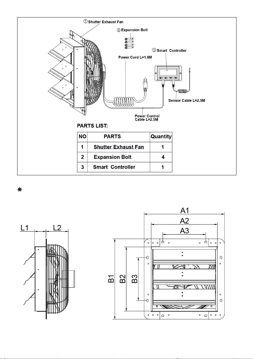
PRODUCT STRUCTURE DIAGRAM
- 5 -
INSTALLATION
TIPS!Prepare tools in advance:
Small wrench,Hammer
- 6 -
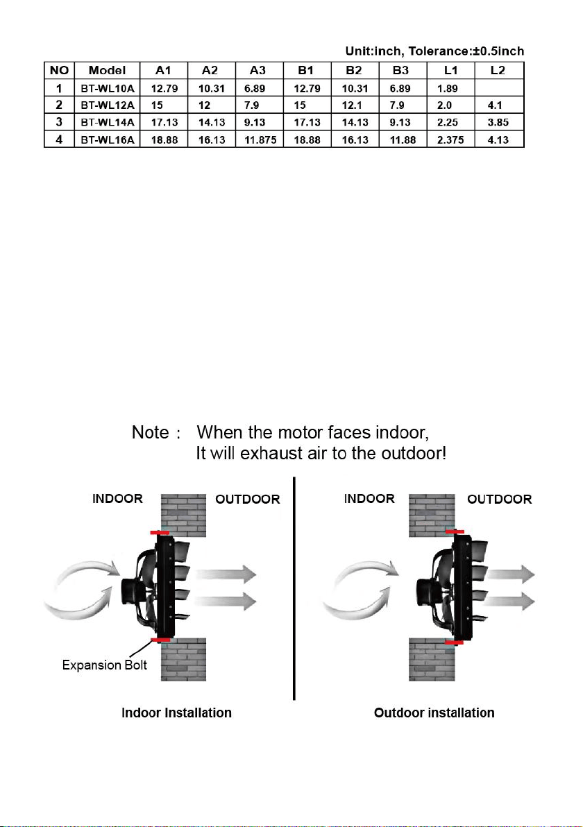
Fig.1.
Before commencing assembly familiarize your self with all the assembly
components and dimensions (See chart and diagram in Fig.1.)
Installation method
1. The product shall be installed at least 3-5 meters above the ground for
ventilation
2. Make a hole on the wall with the size of A2xB2. (Refer to Fig.1. )
3. Punch four holes in the wall,You can choose four holes with the size of
Chart A3 or four holes with the size of B3; (Refer to Fig.1.)
4. Then install the four expansion bolt,You can choose to install indoors or
outdoors (Refer to Fig.2.)
5. Put the product on and lock it with nuts.
Fig.2.
- 7 -
6. Finally connect the lines correctly, (Refer to WIRING DIAGRAM)
Note: Make sure the product is firm and the wiring is right before power
on
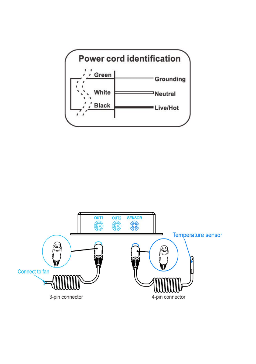
WIRING DIAGRAM
POWERING AND SETUP
Step 1:
Plug the fan’s 3-pin connector into the universal controller’s out 1 or out 2
port signified by the fan/power symbol.Plug the sensor’s 4-pin connector
into the controller’s sensor signified by the controller symbol.See
the(Fig.3.)
Fig.3.
Step 2:
Lastly, to power both the fan and controller, plug the fans power cord into
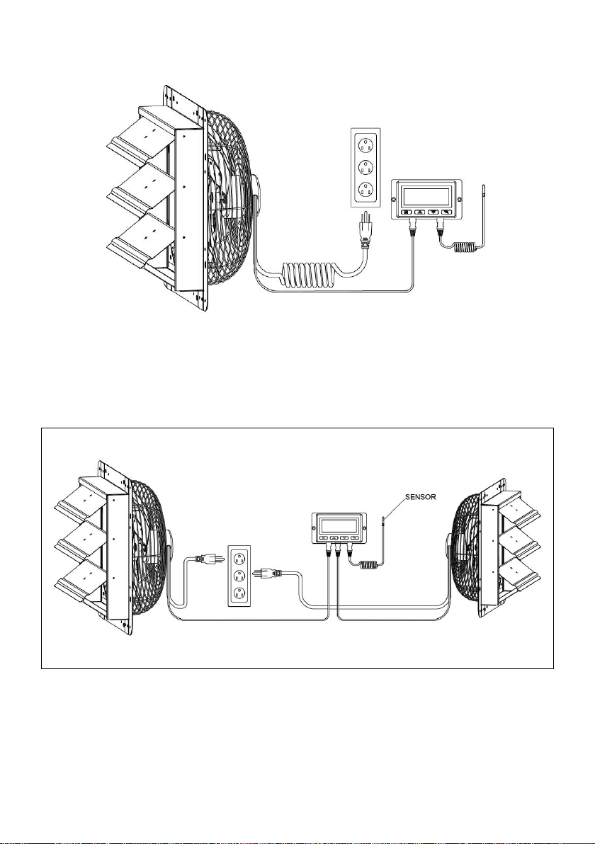
- 8 -
an AC power outlet.See the(Fig.4.)
Fig.4.
Tips:
Smart controllers with EC motors can support two fans of any size. The
two EC-motor fans must be plugged in to an outlet to power the fans and
the controller. See images below.
Dual Connection
EC models can connect two fans of any size
CLEANING:
1.Be sure to unplug from the electrical supply source before cleaning.
2.Plastic parts should be cleaned with mild soap and damp cloth or
sponge. Thoroughly remove soap film with clean water.
3.Be sure not to get water or other liquid into the motor.
- 9 -
PROGRAMMING
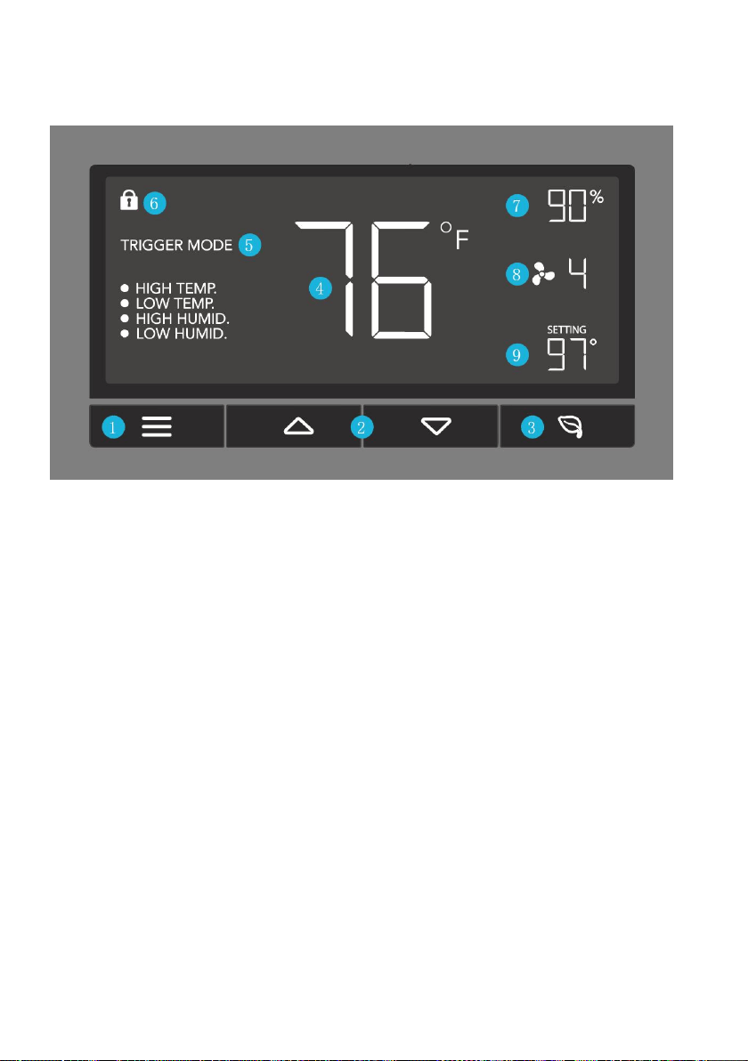
BUTTON DESCRIPTION
1.MODE BUTTON
Cycles through the controller's temperature/humidity programming: ON,
OFF,TIMER, AUTO (4 triggers),and ALARM (4 settings).
2.UP / DOWN BUTTON
Adjusts the settings of the mode that you are in. Up button raises and
down button lowers. Hold both to turn off triggers.
3. LEAF BUTTON
Turns the screen off while programs run in the background. Hold for two
seconds to lock or unlock the LCD display.
4.PROBE TEMP
Displays the current temperature that the corded sensor probe is
measuring. Shows “- -” if no probe is plugged in.
5.CONTROLLER MODE
Displays the mode that the controller is currently in.Pressing the mode
button cycles through the modes.
6.ALERT ICONS

- 10 -
Displays the alerts and statuses from the controller, including the alarm
and the screen lock.
7.PROBE HUMIDITY
Displays the current humidity that the corded sensor probe is measuring.
Shows “- -” if no probe is plugged in.
8.FAN SPEED
Displays the current speed the fan is running at, or what speed it should
be running at if no fans are plugged in.
9.SETTING
Displays the value you set for the current mode. Pressing the up or down
button changes the value.
OPERATION DESCRIPTION
MODE SETTING
Pressing the Mode button will cycle through the controller’s available
programming modes and settings: ON Mode, OFF Mode, TIMER Mode,
AUTO Mode (4 triggers), ALARM Settings (4 settings).
ON MODE
In this mode, the fan will heat continuously regardless of temperature or
humidity. Use this mode to set the fan's maximum blowing strength,
ranging from 0-10, when triggers are activated.
OFF MODE
In this mode, the fan will not run regardless of temperature or humidity.
Pushing the up or down button will change the display’s brightness,
ranging in 1/2/3/A3. On setting A3, the display will dim its brightness down
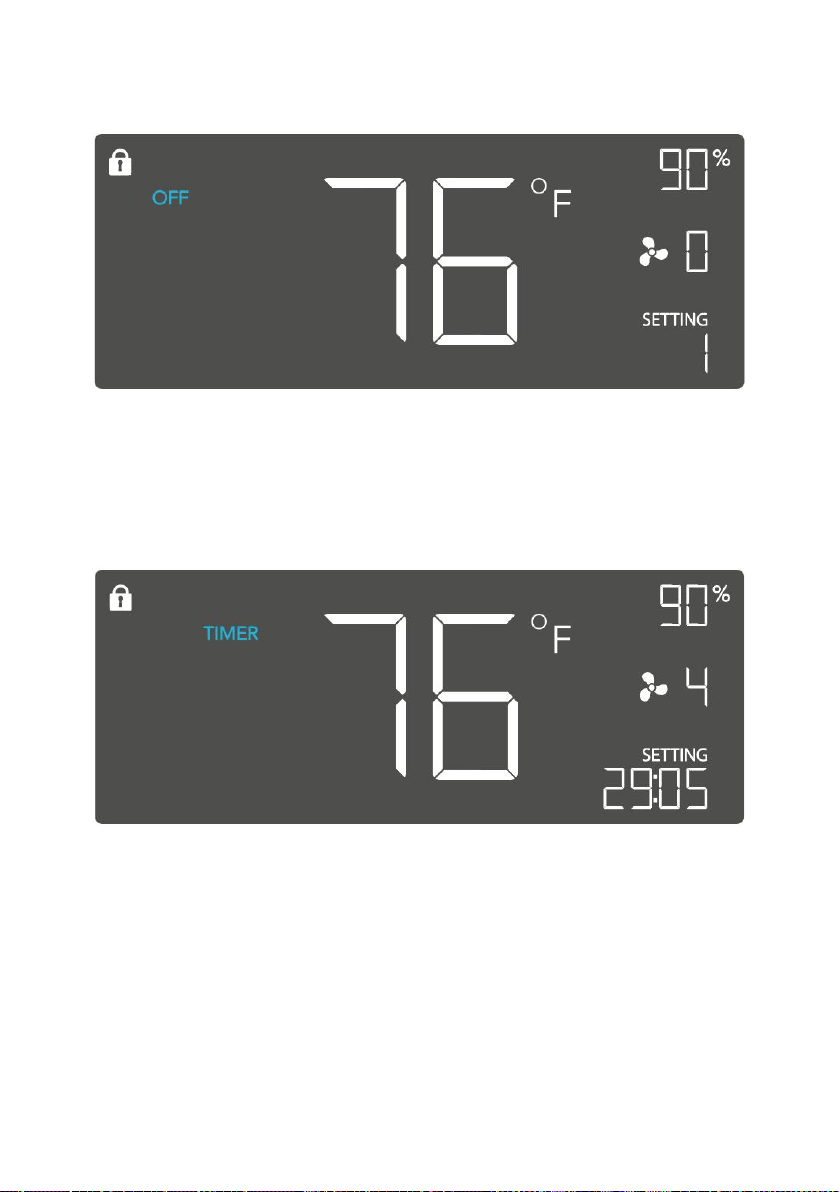
- 11 -
to 1 if the device is left unattended for 30 seconds. Holding the up or down
button will change the display’s units to F or C, respectively.
TIMER MODE
In this mode, pressing the up or down button will set the timer. The fan will
ramp up to ON Mode’s setting until the timer’s clock runs out. It will begin
spinning 5 seconds after the timer is set.
Leaving the timer mode while it’s running will pause it until you return to
this mode.
TRIGGER MODE: HIGH TEMPERATURE
In this mode, pressing the up or down button sets the high temperature
trigger. The fan will activate if the probe’s reading meets or exceeds this
trigger.
It will gradually ramp up until it reaches the ON Mode’s setting. If the
probe’s reading falls below your trigger, the fan will turn off. We
recommend turning this trigger OFF when not in use during set up by
holding the up and down buttons together.
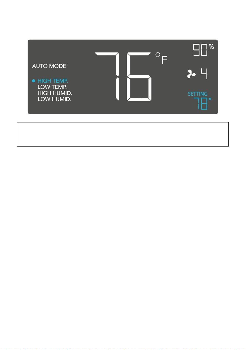
- 12 -
You may set this trigger below the low temperature trigger to create a
range where the fan is active.
Note that this trigger can activate as long as you are in AUTO Mode,
even if you are viewing a different trigger within AUTO Mode.
TRIGGER MODE: LOW TEMPERATURE
In this mode, pressing the up or down button sets the low temperature
trigger. The fan will activate if the probe’s reading meets or falls below this
trigger.
It will gradually ramp up until it reaches the ON Mode’s setting. If the
probe’s reading rises above your trigger, the fan will turn off. We
recommend turning this trigger OFF when not in use during set up by
holding the up and down buttons together.
You may set this trigger above the high temperature trigger to create a
range where the fan is active.
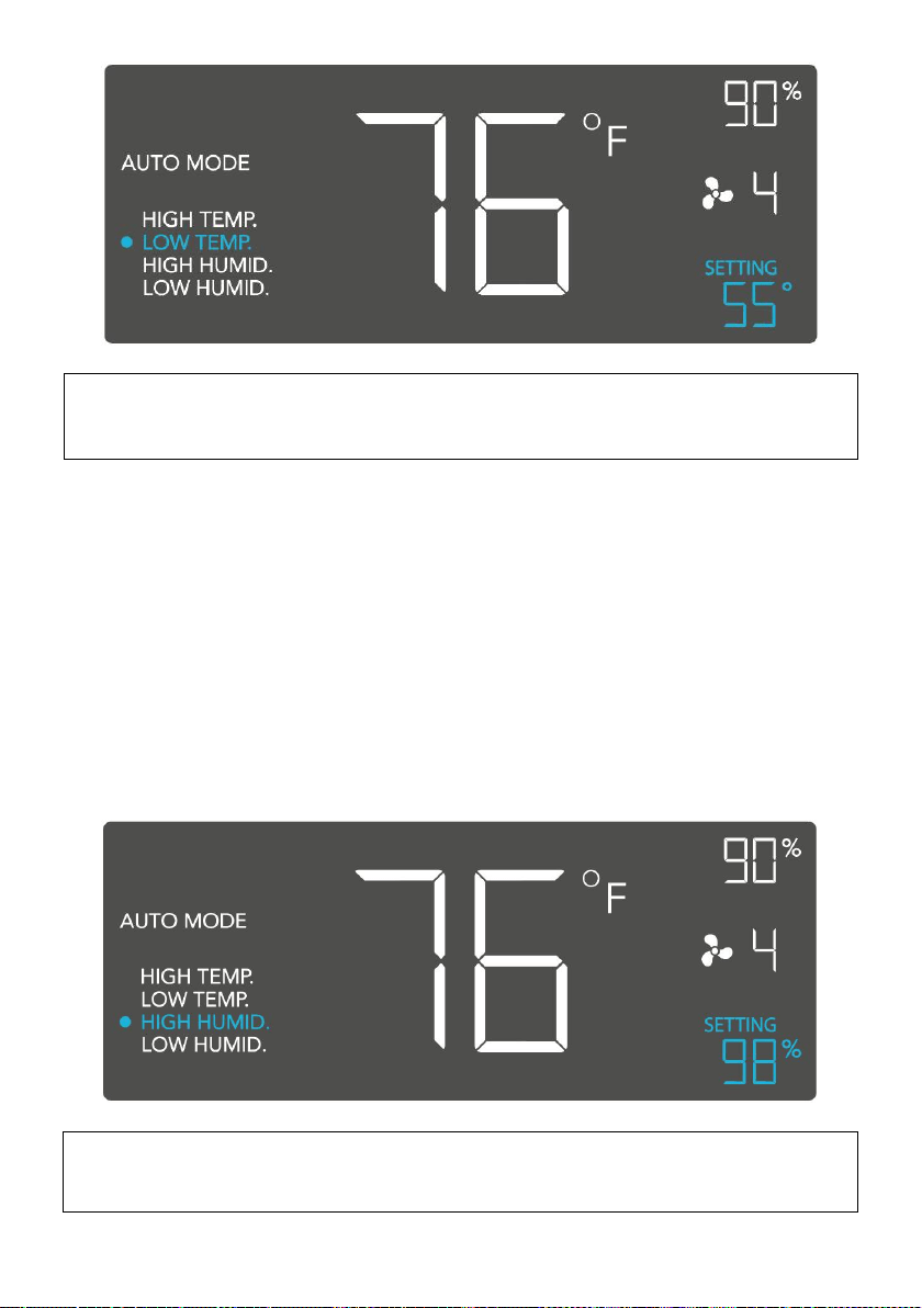
- 13 -
Note that this trigger can activate as long as you are in AUTO Mode,
even if you are viewing a different trigger within AUTO Mode.
TRIGGER MODE: HIGH HUMIDITY
In this mode, pressing the up or down button sets a high humidity trigger.
The fan will activate if the probe’s reading meets or exceeds this trigger.
It will gradually ramp up until it reaches the ON Mode’s setting. If the
probe’s reading falls below your trigger, the fan will turn off. We
recommend turning this trigger OFF when not in use during set up by
holding the up and down buttons together.
You may set this trigger below the low humidity trigger to create a range
where the fan is active.
Note that this trigger can activate as long as you are in AUTO Mode,
even if you are viewing a different trigger within AUTO Mode.
- 14 -
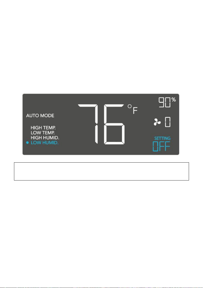
TRIGGER MODE: LOW HUMIDITY
In this mode, pressing the up or down button sets the low humidity trigger.
The fan will activate if the probe’s reading meets or falls below the trigger.
It will gradually ramp up until it reaches the ON Mode’s setting. If the
probe’s reading rises above your trigger, the fan will turn off. We
recommend turning this trigger OFF when not in use during set up by
holding the up and down buttons together.
You may set this trigger above the high humidity trigger to create a range
where the fan is active.
Note that this trigger can activate as long as you are in AUTO Mode,
even if you are viewing a different trigger within AUTO Mode.
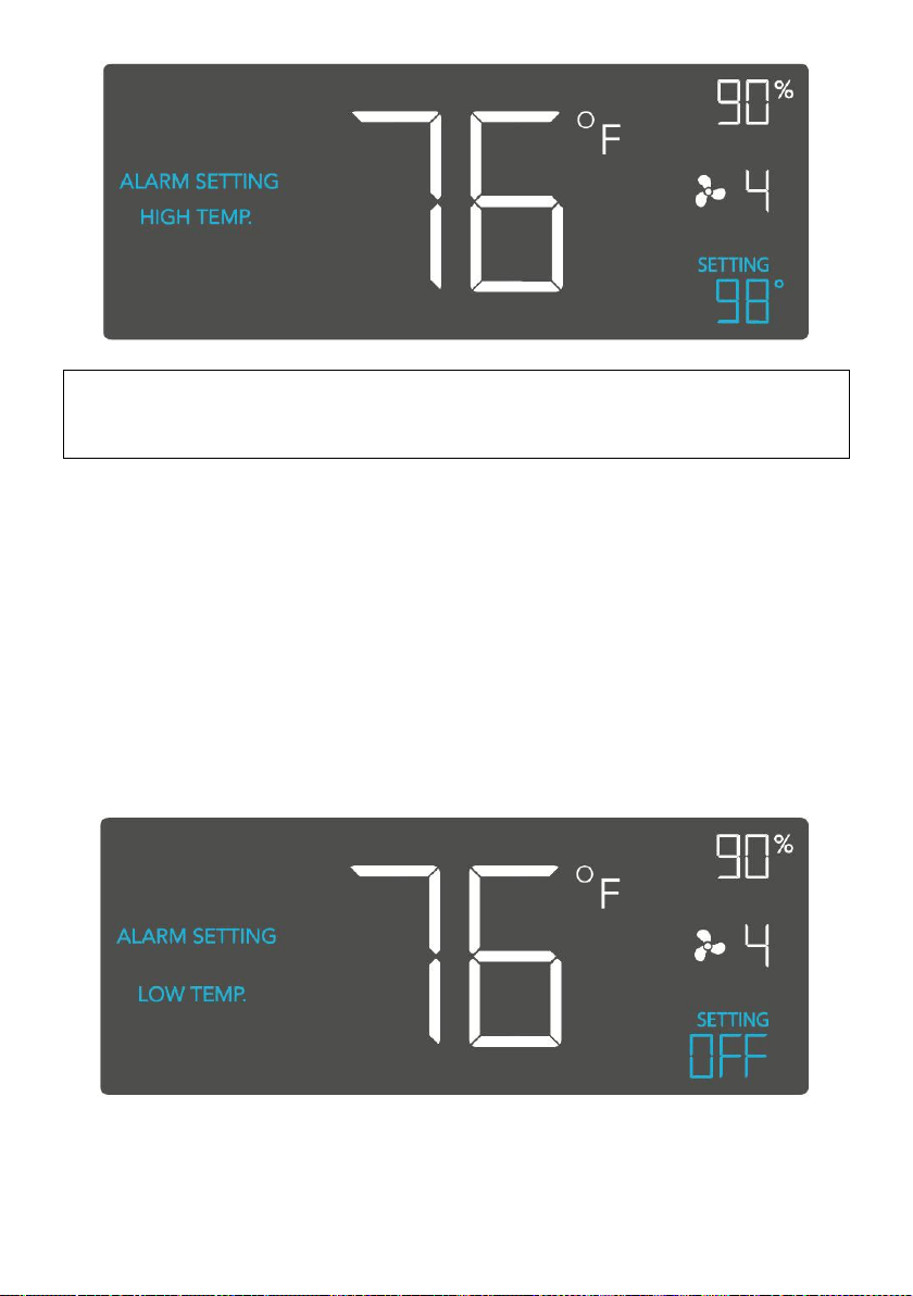
ALARM SETTING: HIGH TEMPERATURE
In this mode, pressing the up and down button sets a high temperature
alarm. The alarm will sound and its icon will flash if the probe’s reading
exceeds the set temperature.
To activate the alarm, leave the alarm mode. The alarm will turn
OFF if the probe’s reading falls below the trigger or if any button is
pressed. You can also set the alarm OFF by holding the up and down
buttons together.
You may set this alarm below the low temperature trigger to create an
operating range.
- 15 -
Note that alarm triggers can only activate in AUTO, ON, or TIMER
Mode. Please leave ALARM SETTING to arm the controller.
ALARM SETTING: LOW TEMPERATURE
In this mode, pressing the up and down button sets a low temperature
alarm. The alarm will sound and its icon will flash if the probe’s reading
falls below the set temperature.
To activate the alarm, leave the alarm mode. The alarm will turn OFF if the
probe’s reading rises above the trigger or if any button is pressed. You
can also set the alarm OFF by holding the up and down buttons together.
You may set this alarm above the high temperature trigger to create an
operating range.
- 16 -
Note that alarm triggers can only activate in AUTO, ON, or TIMER
Mode. Please leave ALARM SETTING to arm the controller.
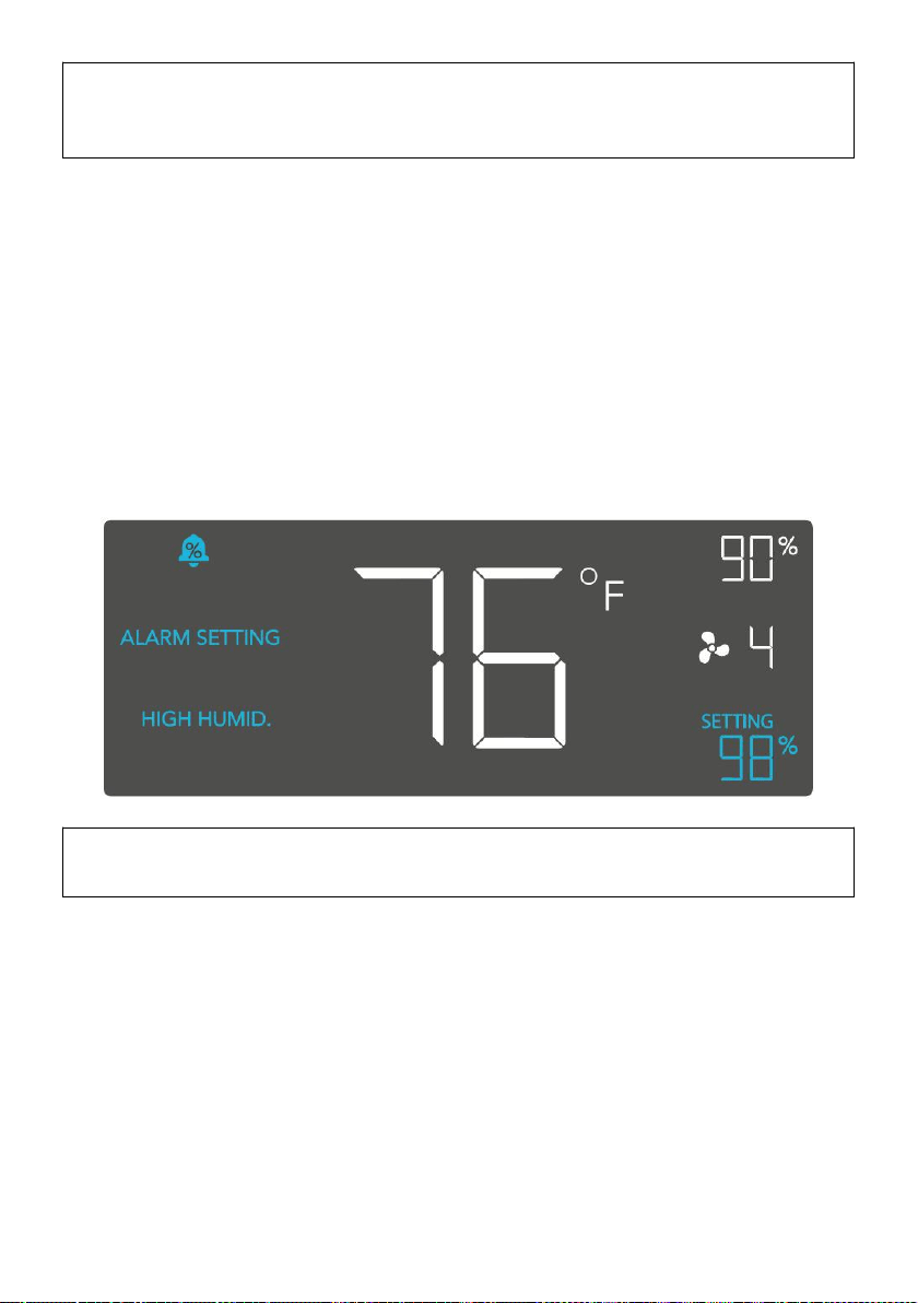
ALARM SETTING: HIGH HUMIDITY
In this mode, pressing the up and down button sets a high humidity alarm.
The alarm will sound and its icon will flash if the probe’s reading exceeds
the set humidity.
To activate the alarm, leave the alarm mode. The alarm will turn OFF if the
probe’s reading falls below the trigger or if any button is pressed. You can
also set the alarm OFF by holding the up and down buttons together.
You may set this alarm below the low humidity trigger to create an
operating range.
Note that alarm triggers can only activate in AUTO, ON, or TIMER
Mode. Please leave ALARM SETTING to arm the controller.
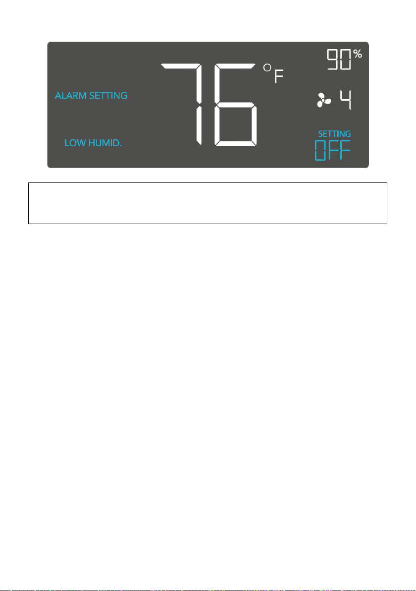
ALARM SETTING: LOW HUMIDITY
In this mode, pressing the up and down button sets a low humidity alarm.
The alarm will sound and its icon will flash if the probe’s reading falls
below the set humidity.
To activate the alarm, leave the alarm mode. The alarm will turn OFF if the
probe’s reading rises above the trigger or if any button is pressed. You
can also set the alarm OFF by holding the up and down buttons together.
You may set this alarm above the high humidity trigger to create an
operating range.
- 17 -
Note that alarm triggers can only activate in AUTO, ON, or TIMER
Mode. Please leave ALARM SETTING to arm the controller.
FAHRENHEIT OR CELSIUS
To switch between Fahrenheit and Celsius readings, set the controller to
OFF Mode. Hold the up button to switch to Fahrenheit (°F) and the down
button to switch to Celsius (°C).
DISPLAY BRIGHTNESS
To adjust the brightness of the display, set the controller to OFF Mode,
then press the up or down button to increase or decrease the brightness
level. The brightness range is 1/2/3/A3.
TEMPERATURE CALIBRATION
To adjust the temperature that the probe sensor is measuring, press the
MODE and UP button simultaneously. This can be done while the
controller is any mode. The calibration cycle ranges from -8°F to 8°F (or -
4°C to 4°C). You may use this setting to match the controller's
temperature reading with your thermostat's reading.
HUMIDITY CALIBRATION
To adjust the probe sensor’s humidity reading, press the MODE and
DOWN button simultaneously. This can be done in any mode. The
calibration cycle ranges from -8% to 8%.
CONTROLLER LOCK
To lock the controller and prevent accidental setting changes, hold the
LEAF button for three or more seconds. While the display is locked, you
- 18 -
will not be able to switch modes or adjust settings. You will only be able to
put the controller in ECO display. Holding the LEAF button for three or
more seconds will unlock the controller.
ECO-MODE
To turn off the LCD display, press the LEAF button. While the screen is off,
all programs, settings, and alarms will run in the background. You can
activate ECO Mode while the controller is locked. To exit ECO mode,
press any button.
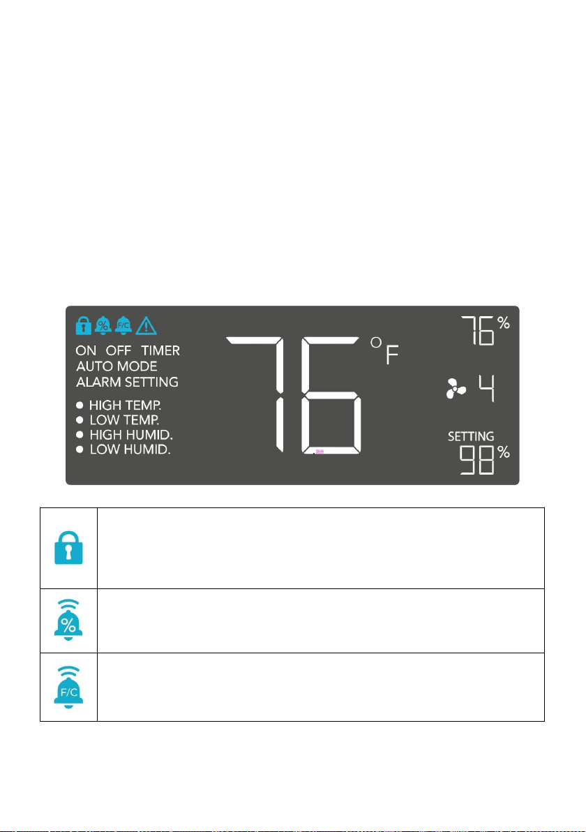
ALERT ICONS
The top left of the display shows the alert icons. Icons may flash when the
controller signals an alert to tell you a particular function or alarm is being
triggered.
DISPLAY LOCK ALERT
This icon is visible when the controller has been locked. The
icon will flash to alert you that the controller is locked if you try
to change the mode or settings.
HUMIDITY ALARM ALERT
This icon will flash when the high or low humidity alarm has
been triggered.
TEMPERATURE ALARM ALERT
This icon will flash when the high or low temperature alarm has
been triggered.

- 19 -
CHECK FAN ALERT
This icon will flash when the fan's probe senses interference to
its functioning. Check the fan for possible issues. If the fan is
not heating up, please see the warranty page for replacement
information.
Manufacturer: Bote electric appliance(Guangdong)Co.,Ltd
Address: 5TH floor,No.28,area 1,Sanlian Industrial Zone,Gulao
Town,Heshan City,Jiangmen,Guangdong
Made In China