Loading ...
Loading ...
Loading ...
CRS amplifiers support star network topology via the
Ethernet port and Dante networking via the Dante port only.
The Ethernet port is designed to allow the remote
control of the amplifier through Armonía Pro Audio Suite
and third party software. The Dante port is reserved to
Dante networking.
7 : 1.IP addressing
Factory default network settings are DHCP/AutoIP,
in order for the amplifier to self-configure when connected to
an existing LAN or PC. Fixed IP policy can also be adopted
and configured through Armonía Pro Audio Suite.
If a DHCP server is not active within the network,
the amplifier platform initiates a stateless address
auto-configuration (i.e. Zero-configuration networking
methodology – Zeroconf): it self assigns a local numeric
network address (of the type 169.254.x.y – 172.31.*.* for
the secondary network if present – with a subnet mask
255.255.0.0) and automatically distributes and resolves the
host names of the networking devices. For setting a static
IP address please refer to the Armonía Pro Audio Suite user
guide.
7 : 1.1. IP Addressing troubleshooting
When connecting the CRS to a network environment it
may happen that Armonía Pro Audio Suite does not discover
or import the amplifier.
Usually this is a problem of IP addressing: both Armonia
and the amplifier must belong to the same subnet. If a
DHCP server is present on the network and a CRS amplifier
is in AUTO IP, networking may become unstable.
As a rule of thumb, turn the DHCP server
on before connecting the amplifiers.
IP addressing of a CRS amplifier is established during
the bootstrap: when the amplifier discovers a DHCP
server on the network during the startup, it negotiates the
networking parameters. If the amplifier does not reveal a
DHCP server on the network during the startup, it set itself
in AUTO IP mode.
Networking
7
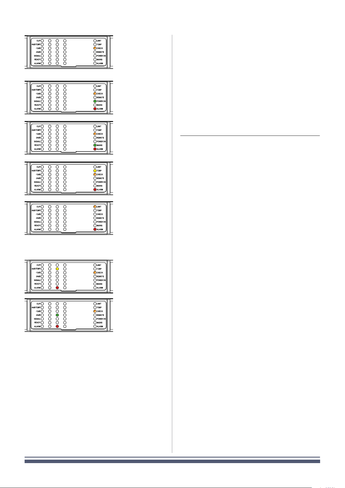
6 : 1.2. Channel faults
If self check cannot be started because of a fault, the
check LED will blink fast, whilst a reassuring slow blink is an
indication of a completed self check procedure.
FIG. 3:
System OK.
FIG. 5:
AC Mains voltage
out of range (over/
under voltage)
FIG. 6:
PSU temperature
out of range
FIG. 7:
Fan Error
FIG. 8:
Channel#
Temperature
out of range
FIG. 9:
Channel#
Output Waveform
non-conformity
6 : 1.1. Global faults
FIG. 4:
Power supply fault
CRS | 17
Loading ...
Loading ...
Loading ...