Loading ...
Loading ...
Loading ...
LED chart
5
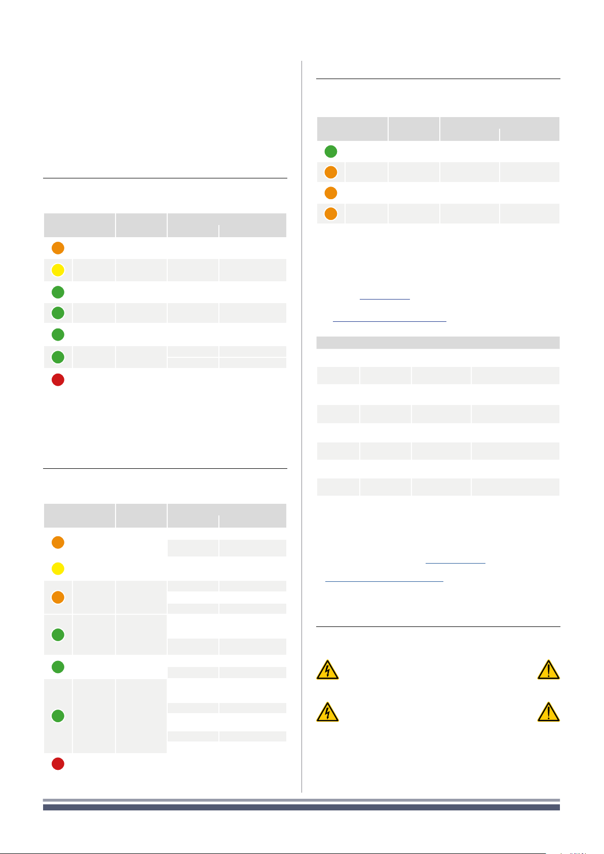
The front LED panel of the amplifier includes four LED
bars for output signal metering and one LED strip with
status indicators. Two operating mode LEDs are located on
the control panel under the left hand cover.
5 : 1.LED bars: signal metering
The four left hand LED bars provide signal metering and
channel status for channels 1 to 4 left to right.
Color
Signal
metering
Warnings
Lighting Description
ORANGE
Clipping
*Limiter Engaged
—
Custom speaker
limiters engaged
YELLOW
-6dB SOLID ON
Thermal warning
Thermal protection
engaged
GREEN
-12dB — —
GREEN
-24dB — —
GREEN
-60dB
SOLID ON Signal presence
BLINKING Channel muted
GREEN
—
SOLID ON Channel ready
FLASHING Auto Standby
RED
—
SOLID ON Channel fault
1
FLASHING User Diagnostic Fault
The “CLIP” LED on the CRS amplifiers is illuminated any time that our pre-
programmed limiters are engaged. These limiters are designed to maximize
both SPL and the life of the drivers. This does not indicate actual clipping
or damage to the amp or speakers.
1
Red LED lights on in case of any kind of channel fault that prevents the normal
channel operating; at the same time the rear corresponding GPO toggles the
contacts NO into NC and NC into NO.
5 : 3.Operating mode LEDs
The operating mode LEDs are located on the control
panel. They state the operating mode when the system
either is on or in standby mode.
Color Name
Operating mode
Standby Power on
GREEN
POWER ON — SOLID ON
ORANGE
STANDBY SOLID ON —
ORANGE
AUTO STANDBY BLINKING —
ORANGE
ERROR CODE BLINK COUNTER —
5 : 2.LED strip: system status
The right hand LED strip on the LED panel provides
system status informations.
Color Name
Warnings
Lighting Description
ORANGE
LIMIT
FLASHING Breaker Save Enabled
SOLID ON
Breaker Save limiting
power draw
YELLOW
TEMP
SOLID ON
Thermal warning
Thermal protection
engaged
ORANGE
CHECK
SOLID ON System self checking
BLINKING Self check completed
FAST BLINKING Self Check Unavailable
GREEN
REMOTE
SOLID ON
Connected to
Armonía or 3rd Party
Remote Control
FLASHING
Preset Changed /
Disconnected
GREEN
POWER ON
SOLID ON System ready
OFF System off
GREEN
MAINS
SOLID ON
AC mains voltage
within the operating
range
OFF Undervoltage
FLASHING
Over/Undervoltage
Warning
FAST BLINKING Overvoltage
SLOW BLINKING Mains FUSES blown
RED
ALARM
SOLID ON
PSU fault
1
OR Critical Faults
1
Red LED lights on in case of any kind of PSU fault that prevents normal
operating.
Control Panel
6
The control panel is located under the left hand metal
cover. See Panel B, p. 4 on how to access the control panel.
The control panel contains two LEDs (for the description
see § 5 : 3.Ope rati ng m ode LED s) and the following controls.
The push-buttons are disabled when connected to Armonìa.
Label Type Action Description
POWER
Pushbutton
keep pressed for
3 seconds
Toggle
system ready/standby mode
CALL
Pushbutton press
Highlight the amplifier in the
Armonía workspace
SOFT
RESET
1
Pushbutton
keep pressed for
3 seconds
Reset network parameters
to factory default
HARD
RESET
1
Pushbutton
keep pressed for
3 seconds
Reboot the system
CHECK
2
Pushbutton
keep pressed for
3 seconds
Start the self-checking
procedure*
CH1
3
Potentiometer
turn
counter-clockwise
Attenuate the output level of
the signal on channel 1
CH2
3
Potentiometer
turn
counter-clockwise
Attenuate the output level of
the signal on channel 2
CH3
3
Potentiometer
turn
counter-clockwise
Attenuate the output level of
the signal on channel 3
CH4
3
Potentiometer
turn
counter-clockwise
Attenuate the output level of
the signal on channel 4
1. Keep pressed both the SOFT RESET button and the HARD
RESET button for at least 3 seconds to completely reset the
amplifier to its factory default configuration (any preset stored in
the internal memory will be lost and replaced with a flat preset).
2. For further information see
§ 6 : 1. Se lf ch ec k.
3. The potentiometer is in series with the remote level control (see
§4 : 2.1. Remote level adjustment) so it can be used to limit the
output volume regardless to any remote adjustment.
* Press again to resume normal operations
6 : 1.Self check
The self check procedure tests the amplifier status and
reports the user in case of failures.
It is highly recommended to unplug the
output connectors before proceeding
with the self check procedure
The testing signals might cause
loudspeaker impairments.
After few minutes, at the end of the self check procedure,
a combination of lighten LED in the LED panel provide
information about the amplifier status.
In order to exit the self check test and resume normal
operations, press once the self check push button.
16 | Component Rack System
Loading ...
Loading ...
Loading ...