
perator's
I:RnFrSMRN°
TWO BiN BAGGER
Model No. 247.24019.1
\
• Espanol, p. 18
iMPORTANT:
Read and follow all Safety
Rules and instructions before
operating this equipment.
For answers to your questions about
this product, Call:
1-800=659=5917
Craftsman Tractor Help Line
7 am = 7 pm CT, Mort. =Sun.
Sears Brands Management Corporation, Hoffman Estates, IL 60179 U.S.A.
Visit our website: www.craftsman.com FormNo.769-05633F
(November14,2011)

Safe Operation Practices .............................................. 3-4
Slope Guide ....................................................................... 5
Contents of Carton & Hardware Packs .......................... 6-7
Assembly and Installation ............................................ 8-14
Operation ........................................................................ 15
Parts List .................................................................... 16-17
Espa_ol ............................................................................ 18
Service Numbers ............................................. Back Cover
Craftsman Full Warranty
Ifthis Craftsmanproductfailsdueto a defectin materialor workmanshipwithinoneyearfromthe dateof purchase,returnit to any Searsstoreor
otherCraftsmanoutlet in the UnitedStatesfor free replacement.
ThiswarrantycoversONLYdefectsin materialandworkmanship.Searswill NOTpayfor:
• Replacementof bags,which are expendableitemsthatcan wearoutfromnormalusewithin thewarrantyperiod.
• Repairsnecessarybecauseof accidentor failureto operateor maintainthe productaccordingto all suppliedinstructions.
Thiswarrantyappliesforonly 90 days if this productis everusedfor commercialor rentalpurposes.
Thiswarrantyappliesonly whilethisproductis usedin the UnitedStates.
Thiswarrantygivesyou specificlegal rights,and you mayalso haveotherrightswhich vary from stateto state.
Sears Brands ManagementCorporation., Hoffman Estates, IL 60179
© KCD IR LLC 2
Thissymbolpointsout importantsafetyinstructionswhich,if not
followed,couldendangerthepersonalsafetyand/orpropertyof
yourselfandothers. Readand followall instructionsin this manual
beforeattemptingto operatethismachine.Failureto complywith
theseinstructionsmayresultin personalinjury.Whenyou seethis
symbol,HEEDITSWARNING!
CALIFORNIA PROPOSITION 65
EngineExhaust,someof itsconstituents,andcertainvehicle
componentscontainoremitchemicalsknownto Stateof California
to cause cancerand birthdefectsor other reproductiveharm.
Batteryposts,terminals,and relatedaccessoriescontainleadand
leadcompounds,chemicalsknownto the Stateof Californiato
causecancerandreproductiveharm.Washhandsafterhandling.
Thisattachmentwas builtto be usedaccordingto the safeopera-
tion practicesin this manual.Carelessnessor erroron the part of
the operatorcan resultin seriousinjury.Mowersarecapableof
amputatinghandsandfeetand throwingobjects.Failureto observe
the followingsafetyinstructionsas wellas the instructionsprovided
withyour mower,could resultin seriousinjuryor death.
Your Responsibility--Restrict the useof this powermachineto
personswho read,understandandfollow thewarningsand instruc-
tionsin thismanualandon the machine.
SAVE THESE INSTRUCTIONS!
GENERAL OPERATION
,, Read,understand,and followall instructionson your equipmentand
intheir manualsbeforeattemptingto assembleand operate.Keepthis
manualina safe placefor futureand regularreferenceandfor ordering
replacementparts.
,, Tohelpavoid bladecontact ora thrown objectinjury,keepbystanders,
helpers,childrenand pets at least 75 feetfrom the mowerwhile it is in
operation.Stop machineif anyoneentersthe area.
,, Thoroughlyinspectthe area wherethe equipmentis to be used.Remove
all stones,sticks, wire, bones, toys,and other foreignobjectswhich
couldbe pickedup and thrownby the blade(s).Thrownobjects can
causeseriouspersonalinjury.
,, Alwayswearsafetyglassesor safetygogglesduringoperationand while
performinganadjustmentor repairto protectyoureyes.Thrownobjects
whichricochet can causeseriousinjury to the eyes.
,, Do not operatethe mowerwithoutthe dischargecoveror entiregrass
catcherinits properplace.A missingor damageddischargecoveror
grass bagattachmentcomponentmayresult inthrown objectsor blade
contactinjuries.
,, Do not puthands or feet near rotatingparts or underthe cutting deck.
Contactwiththe blade(s)can amputatehandsand feet.
,, Shut off mower'sengineand waitfor bladesto come to a completestop
beforeuncloggingmower'sdischargeopeningor baggerparts.
,, Slow downbeforeturning. Operatethe machinesmoothly.Avoiderratic
operationandexcessivespeed. Be awarethat a grasscatcherattach-
mentcan affectthe handlingcharacteristicsof your mower.
,, Disengageblade(s),set parkingbrake,stopengineand waituntil the
blade(s)cometo a completestop beforeopeningbaggerattachment's
top cover,removinggrass catcher,emptyinggrass,uncloggingchute,
removingany grass or debris, or makingany adjustments.
,, Neverleave a runningmachineunattended.Alwaysturn off blade(s),
placetransmissionin neutral,set parkingbrake,stop engine andremove
keybeforedismounting.
,, Your machineis designedto cut normalresidentialgrassof a heightno
morethan 10".Do notattemptto mowthroughunusuallytall, dry grass
(e.g.,pasture)or pilesof dry leaves.Drygrass or leavesmay contact
the engineexhaustand/or build up on the mowerdeck presentinga
potentialfirehazard.
,, If situationsoccur whichare notcoveredinthis manual,use care and
good judgment.Contact 1-800-659-5917for assistance.
3
SLOPE OPERATION
Slopesare a majorfactor relatedto lossof controlandtip-overaccidents
whichcan resultinsevere injury or death.Attachmentscan also affect the
stabilityof the machine.All slopes requireextra caution.
For yoursafety,use the slope gaugeincludedas part of this manualto
estimatetheangle of slopes beforeoperatingthis machineon a slopedor hilly
area.If theslope is greaterthan 10degreesas shown on the slopeguide,do
notoperatethe mowerwiththe grass bagattachmentinstalledon that areaor
seriousinjury could result.
DO:
1. Mow up anddown slopes,not across.Exerciseextremecautionwhen
changingdirectionon slopes.
2. Watchfor holes,ruts,bumps,rocks,or other hiddenobjects. Uneven
terraincouldoverturnthe machine.Tall grasscan hide obstacles.
3. Useslow speed. Choosea low enoughspeedsetting sothat you will not
haveto stopor shift whileon the slope.Tires may losetractionon slopes
eventhoughthe brakes arefunctioningproperly.Alwayskeepmachine
in gear when goingdownslopesto take advantageof enginebraking
action.
4. Followthe manufacturer'srecommendationsfor wheelweightsor
counterweightsto improvestability. For recommendations,contact
1-800-659-5917.
5. Keepall movementon the slopes slow and gradual.Do not makesud-
denchangesin speedor direction.Rapidengagementor brakingcould
causethefront of the machineto lift and rapidlyflip overbackwards
whichcould causeserious injury.
6. Avoidstartingor stoppingon a slope.If tires losetraction,disengagethe
blade(s) andproceedslowly straightdownthe slope.
DO NOT:
1. Do not turn on slopesunlessnecessary;then, turn slowlyand gradually
downhill,if possible.
2. Do not mow near drop-offs,ditchesor embankments.The mowercould
suddenlyturn over if a wheel is overthe edgeof a cliff,ditch,or if an
edge caves in.
3. Do not try to stabilizethe machineby putting yourfooton the ground.
4. Do not use a grasscatcher on steepslopes.
5. Do not mow on wet grass. Reducedtractioncould causesliding.
GENERAL SERVICE
1. Beforecleaning, repairing,or inspecting,makecertainthe blade(s)
and all movingparts havestopped. Disconnectthe spark plug wireand
ground againsttheengine to preventunintendedstarting.
2. Keep all nuts, bolts,and screwstightto be surethe equipmentis in safe
workingcondition.
3. Nevertamperwith yourmower'ssafetyinterlocksystemor othersafety
devices.Checktheir properoperationregularly.
4. Neverattemptto makeadjustmentsor repairswhile themower'sengine
is running.
5. Grasscatchercomponentsandthe dischargecoverare subjectto wear
and damagewhichcouldexpose movingpartsor allowobjectsto be
thrown.For safetyprotection,frequentlycheck componentsand replace
immediatelywith originalequipmentmanufacturer's(O.E.M.)parts only,
listed inthis manual.Use of parts whichdo not meetthe originalequip-
ment specificationsmay leadto improperperformanceandcompromise
safety!
6. Maintainor replacesafetyand instructionlabels, as necessary.
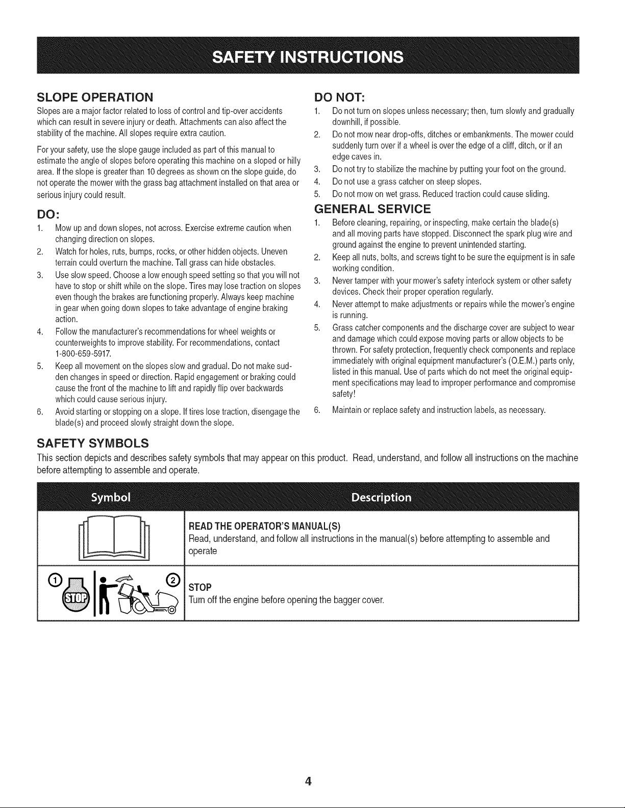
SAFETY SYMBOLS
This section depicts and describes safety symbols that may appear on this product. Read, understand, and follow all instructions on the machine
before attempting to assemble and operate.
I
I
READTHEOPERATOR'SMANUAL(S)
Read,understand,andfollowall instructionsin the manual(s)beforeattemptingto assembleand
operate
STOP
Turnoff the enginebeforeopeningthe baggercover.
4
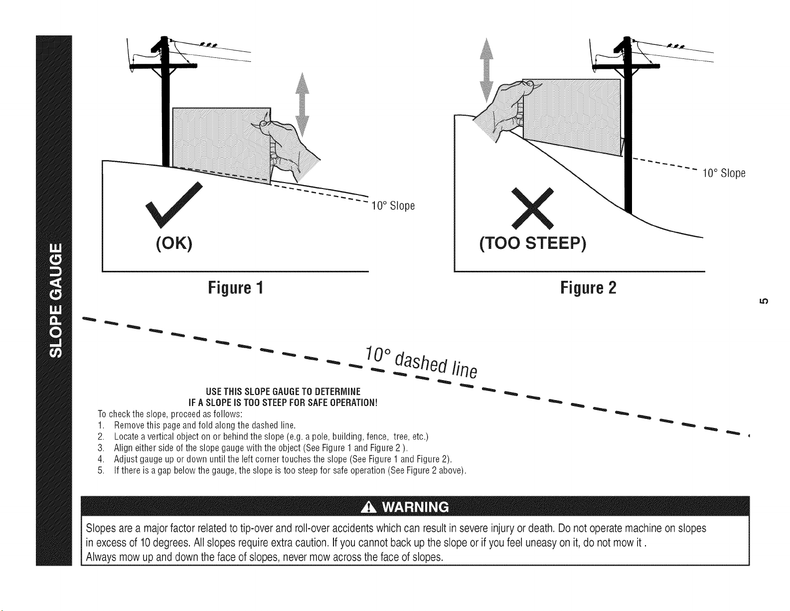
(OK)
10° Slope
(TOO STEEP)
10° Slope
Figure 1
USETHiSSLOPEGAUGETO DETERMINE
iFA SLOPEiS TOOSTEEPFORSAFEOPERATION!
Tocheckthe slope,proceedas follows:
1. Removethis pageandfold alongthe dashedline.
2. Locateavertical object on or behindthe slope(e.g. a pole,building,fence, tree,etc.)
3. Aligneither sideof the slopegaugewiththe object (SeeFigure1 and Figure2 ).
4. Adjustgaugeup or down until the left cornertouchesthe slope(SeeFigure1 andFigure2).
5.
10odashedline
If there is a gapbelowthe gauge,the slope is too steepfor safeoperation(SeeFigure2 above).
Figure2
Slopes are a majorfactor related to tip-over and roll-over accidents which can result in severe injury or death. Do not operate machine on slopes
in excess of 10degrees. All slopes requireextra caution, if you cannot back up the slope or if you feel uneasy on it, do not mow it.
Always mow up and down the face of slopes, nevermow across the face of slopes.
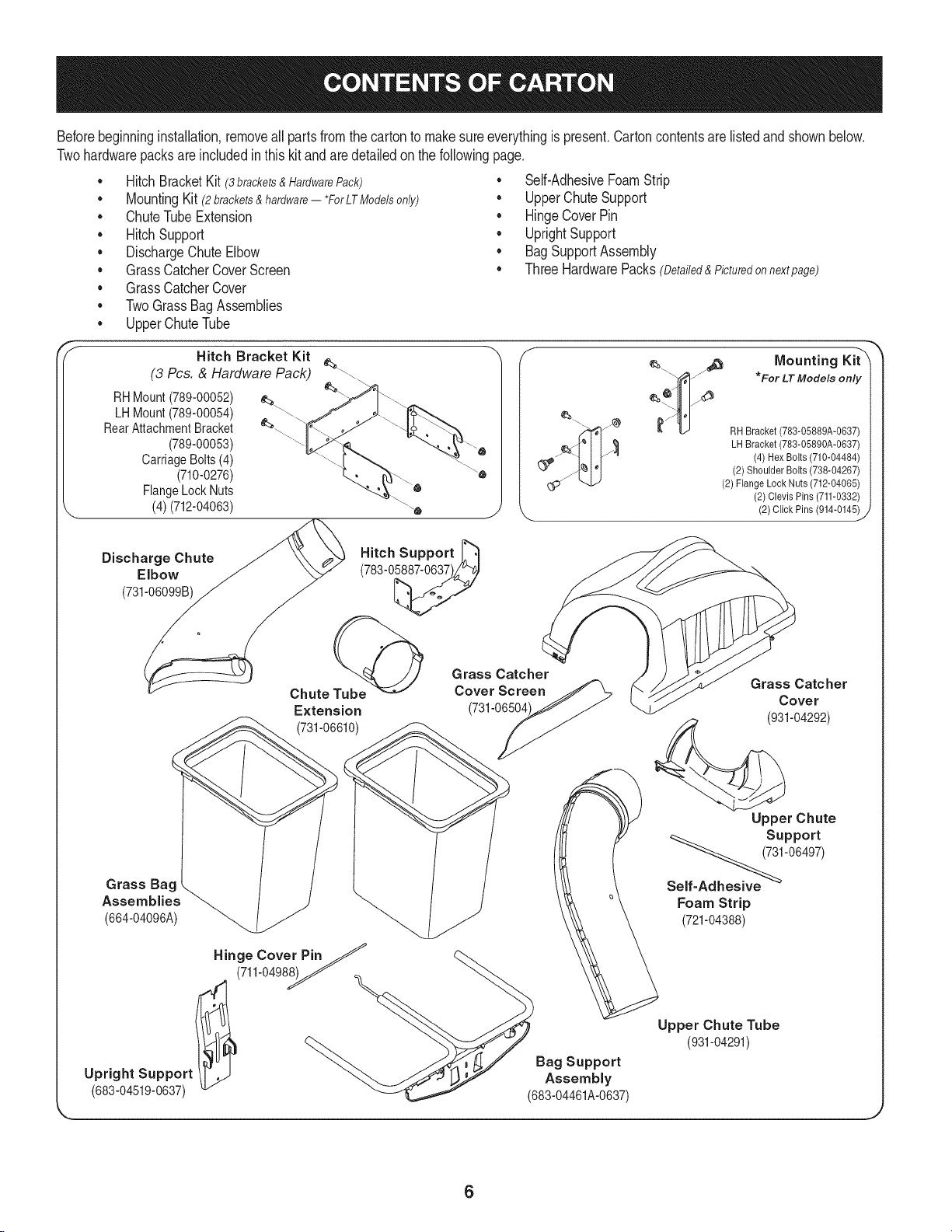
Beforebeginninginstallation,removeall partsfrom the cartonto makesureeverythingis present.Cartoncontentsare listedand shownbelow.
Twohardwarepacksare includedin this kit and are detailedon thefollowingpage.
• HitchBracketKit (3 brackets & Hardware Pack)
MountingKit (2brackets&hardware-- *ForLTModelsonly)
• ChuteTubeExtension
• HitchSupport
• DischargeChute Elbow
• GrassCatcherCoverScreen
• GrassCatcherCover
• TwoGrassBag Assemblies
• UpperChuteTube
Hitch Bracket Kit
(3 Pcs. & Hardware Pack) __.\
• Self-AdhesiveFoamStrip
• UpperChuteSupport
• HingeCoverPin
• UprightSupport
• BagSupportAssembly
• ThreeHardwarePacks(Detailed&Picturedon nextpage)
Mounting Kit"X
*For LT Models only
RHMount(789-00052)
LHMount(789-00054)
RearAttachmentBracket
(789-00053)
CarriageBolts (4)
(710-0276)
FlangeLock Nuts
(4) (712-04063)
RH Bracket (783-05889A-0637)
_ LH Bracket (783-05890A-0637)
(4) Hex Bolts (710-04484)
(2) Shoulder Bolts (738-04267)
(2) FlangeLock Nuts (712-04065)
(2)Clevis Pins (711-0332)
(2) Click Pins (914-0145)
_J
Discharge Chute
Elbow
(731-06099B)
Hitch Support _"_
(783-0_
Chute Tube@
Extension
(731-06610)
Grass Catcher
Cover Screen
(731-06504
Grass Catcher
Cover
(931-04292)
Grass Bag .
Assemblies _(664-04096A)
Hinge Cover PinJ
(711-0498__
Bag Support
Upright Support Assembly
(683-04519-0637) (683-04461A-0637)
Upper Chute
Support
Self_'06497)
Foam Strip
(721-04388)
Upper Chute Tube
(931-04291)
6
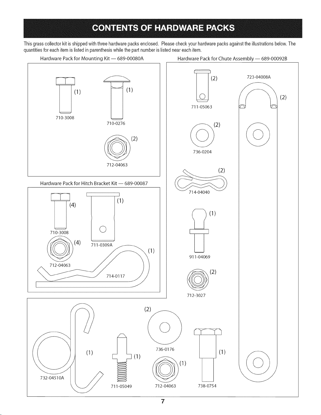
Thisgrasscollectorkit is shippedwith threehardwarepacksenclosed. Pleasecheckyourhardwarepacksagainstthe illustrationsbelow.The
quantitiesforeach itemis listedin parenthesiswhilethe part numberis listedneareachitem.
Hardware Pack for Mounting Kit -- 689-00080A Hardware Packfor Chute Assembly-- 689-00092B
1) )
710-3008
710-0276
(2)
712-04063
Hardware Pack for Hitch Bracket Kit- 689-00087
4)
710-3008
(4)
712-04063
I
©
711-0309A
I
(1)
714-0117
732-04510A
711-05049
I)
(2) 723-04008
711-05063
(2)
736-0204
(2)
714-04040
E_(1)
911-04069
(2)
712-3027
(2)
(1)
736-0176
712-04063 738-0754
-h
(1)
(2)
7
identify The Model of Tractor
Thismanualis designedfor installationof thisnewbagginguniton
severaldifferentmodelsof tractors. Itis importantfor youto determine
whichmodelof tractorthatyou have. Oncethisis known,followthe
pertinentsetof instructionson thefollowingpages.
Todeterminewhich modelof tractoryou have,lookat the tractor's
modelplate,locatedunderthe seat. Simplyflip the seatupand locate
the modelplate,whichwill includethe modelnumber(e.g.Lawn
Tractor247.XXXXX)andserialnumber.
Ifyou are assemblingthis baggerunitfor use onany LTSeries lawn
tractor,you will needto installthetwo tractormountingbrackets
packedinyour baggerkit. Ifyou are installingthis baggeruniton any
YT Series yardtractor,disregardthesestepsandmoveto Assemble
MountingBrackets.
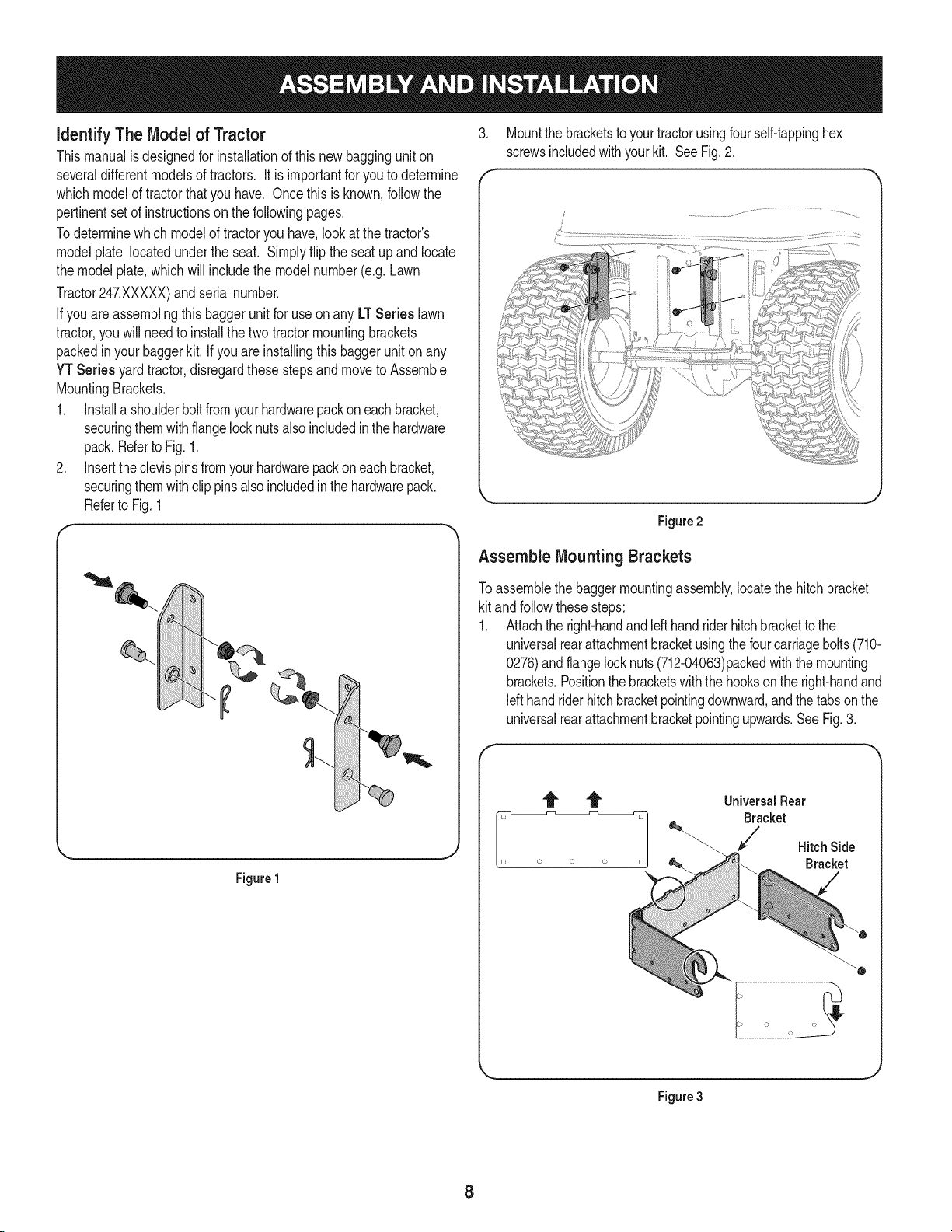
1. Installa shoulderboltfromyourhardwarepackon eachbracket,
securingthemwithflangelocknutsalsoincludedin thehardware
pack.Referto Fig.1.
2. Insertthe clevispinsfromyourhardwarepackon eachbracket,
securingthemwithclip pinsalso includedinthe hardwarepack.
Referto Fig.1
Figure1
J
.
f
Mountthe bracketstoyourtractorusingfour self-tappinghex
screwsincludedwithyourkit. SeeFig. 2.
L.
Figure2
Assemble Mounting Brackets
Toassemblethe baggermountingassembly,locatethe hitchbracket
kit andfollowthesesteps:
1. Attachthe right-handand Idt handrider hitchbracketto the
universalrearattachmentbracketusingthefourcarriagebolts(710-
0276)andflangelocknuts(712-04063)packedwiththemounting
brackets.Positionthebracketswiththe hooksonthe right-handand
Idt handriderhitchbracketpointingdownward,andthe tabsonthe
universalrearattachmentbracketpointingupwards.SeeFig.3.
f
UniversalRear
Bracket
Hitch Side
Bracket
i o o
Figure3
8
Note: Thisuniversalmountingbracketassemblyis designedto
workwithotheravailableattachments,such as aweight kit used in
conjunctionwiththe snow bladeor snowthrowerattachment. Utilize
the contactinformationon the frontor backcoverof this manual,or
contactthe storein whichyou purchasedthisequipmentto findout
moreaboutavailableattachmentsfor yourspecifictractor.
.
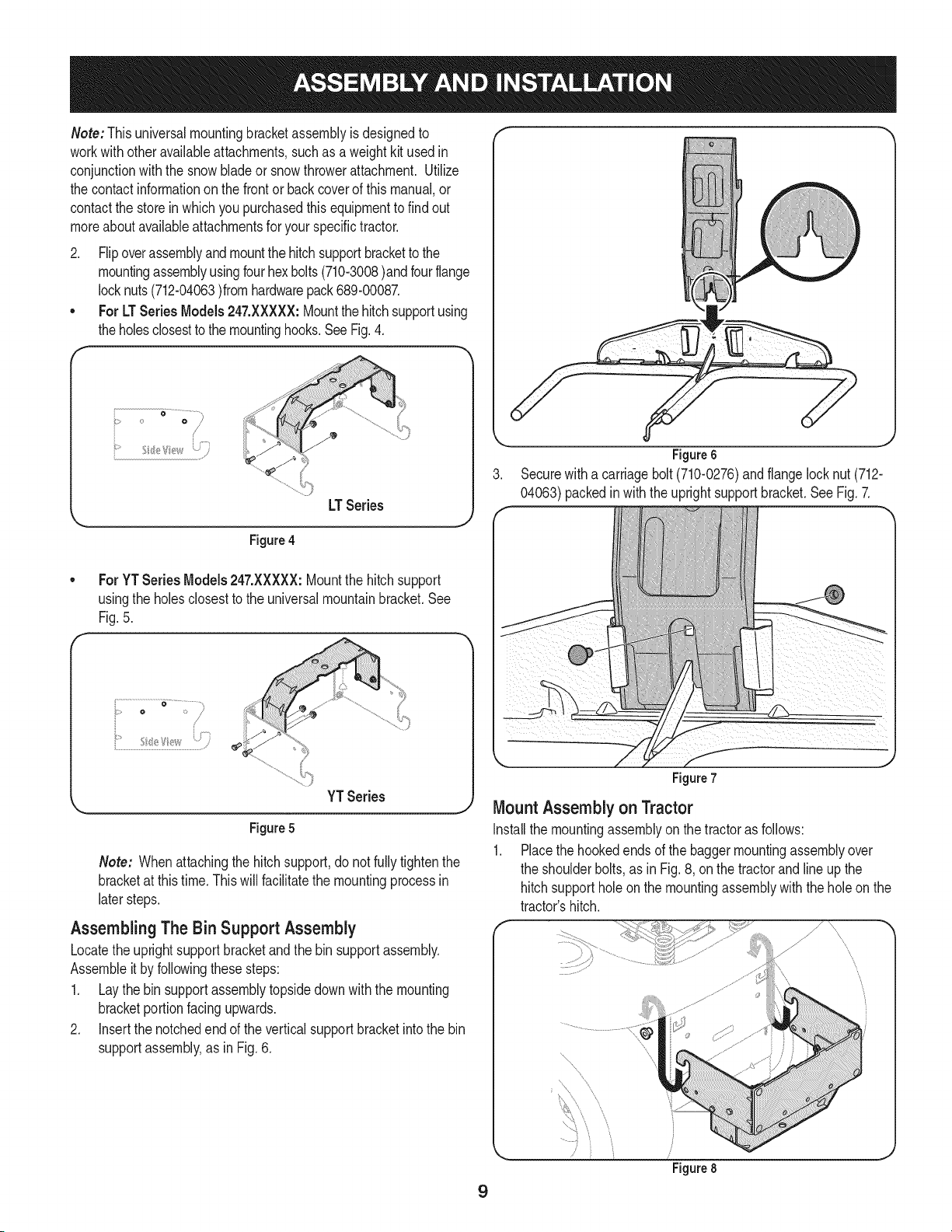
Flipoverassemblyand mountthe hitchsupportbracketto the
mountingassemblyusingfourhexbolts(710-3008)andfourflange
locknuts(712-04063)fromhardwarepack689-00087.
For LT SeriesModels 247.XXXXX:Mountthe hitchsupportusing
theholesclosestto themountinghooks.SeeFig.4.
_" ...... i?_;_
.................,,)
LTSeries
J
Figure4
Figure6
Securewitha carriagebolt (710-0276)and flangelocknut (712-
04063)packedinwiththe uprightsupportbracket.SeeFig. 7.
F
For YT Series Models247.XXXXX:Mountthe hitchsupport
usingthe holesclosestto the universalmountainbracket.See
Fig.5.
i...............................................................................•
YT Series
Figure 5
J
Note: Whenattachingthe hitchsupport,do notfully tightenthe
bracketat this time.Thiswill facilitatethe mountingprocessin
latersteps.
Assembling The Bin Support Assembly
Locatethe uprightsupport bracketand the binsupportassembly.
Assembleitby followingthesesteps:
1. Laythe bin supportassemblytopsidedownwith the mounting
bracketportionfacingupwards.
2. Insertthe notchedend of the verticalsupportbracketintothe bin
supportassembly,as in Fig. 6.
9
Figure 7
Mount Assembly on Tractor
Installthe mountingassemblyon the tractoras follows:
1. Placethe hookedendsof the baggermountingassemblyover
the shoulderbolts,as in Fig. 8, onthe tractorandlineup the
hitchsupportholeon the mountingassemblywiththe holeon the
tractor'shitch.
\
\
\
\
\
........ ,
Figure 8
J
.
.
4.
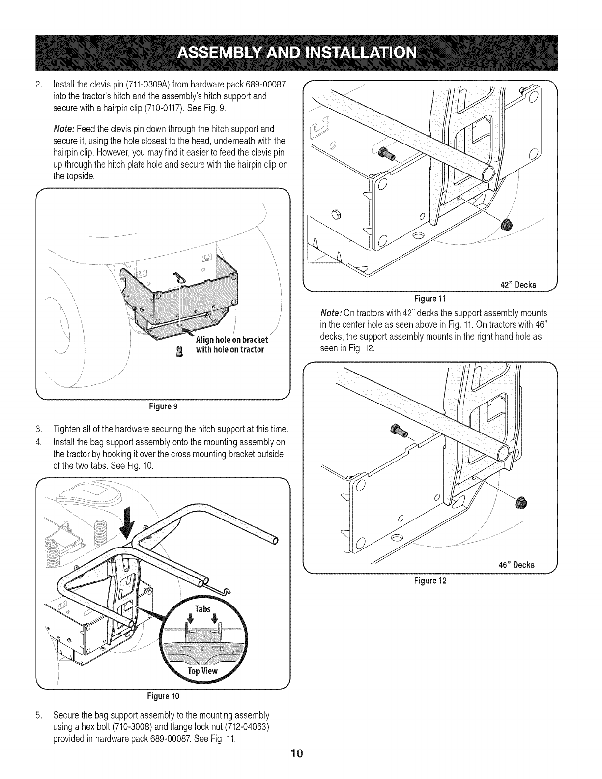
Installtheclevis pin (711-0309A)fromhardwarepack689-00087
intothe tractor'shitchand the assembly'shitchsupportand
securewitha hairpinclip (710-0117).See Fig. 9.
Note: Feedtheclevis pindownthroughthe hitchsupportand
secureit, usingthe holeclosestto the head,underneathwith the
hairpinclip.However,you mayfind it easierto feedthe clevispin
upthroughthe hitchplate holeand securewith the hairpinclip on
thetopside.
\
/
/
\
\
Figure9
Tightenallof the hardwaresecuringthe hitchsupportat thistime.
Installthe bagsupportassemblyontothe mountingassemblyon
thetractorby hookingitoverthe crossmountingbracketoutside
of the twotabs.See Fig. 10.
Figure10
/
/
L_ 4211Decks _
Figure11
Note: On tractorswith 42" decksthe supportassemblymounts
in the centerhole as seenabovein Fig.11.On tractorswith 46"
decks,the supportassemblymountsinthe righthandholeas
seen in Fig. 12.
46" Decks
Figure 12
.
Securethe bag supportassemblytothe mountingassembly
usinga hexbolt (710-3008)and flangelocknut(712-04063)
providedinhardwarepack689-00087.SeeFig. 11.
10
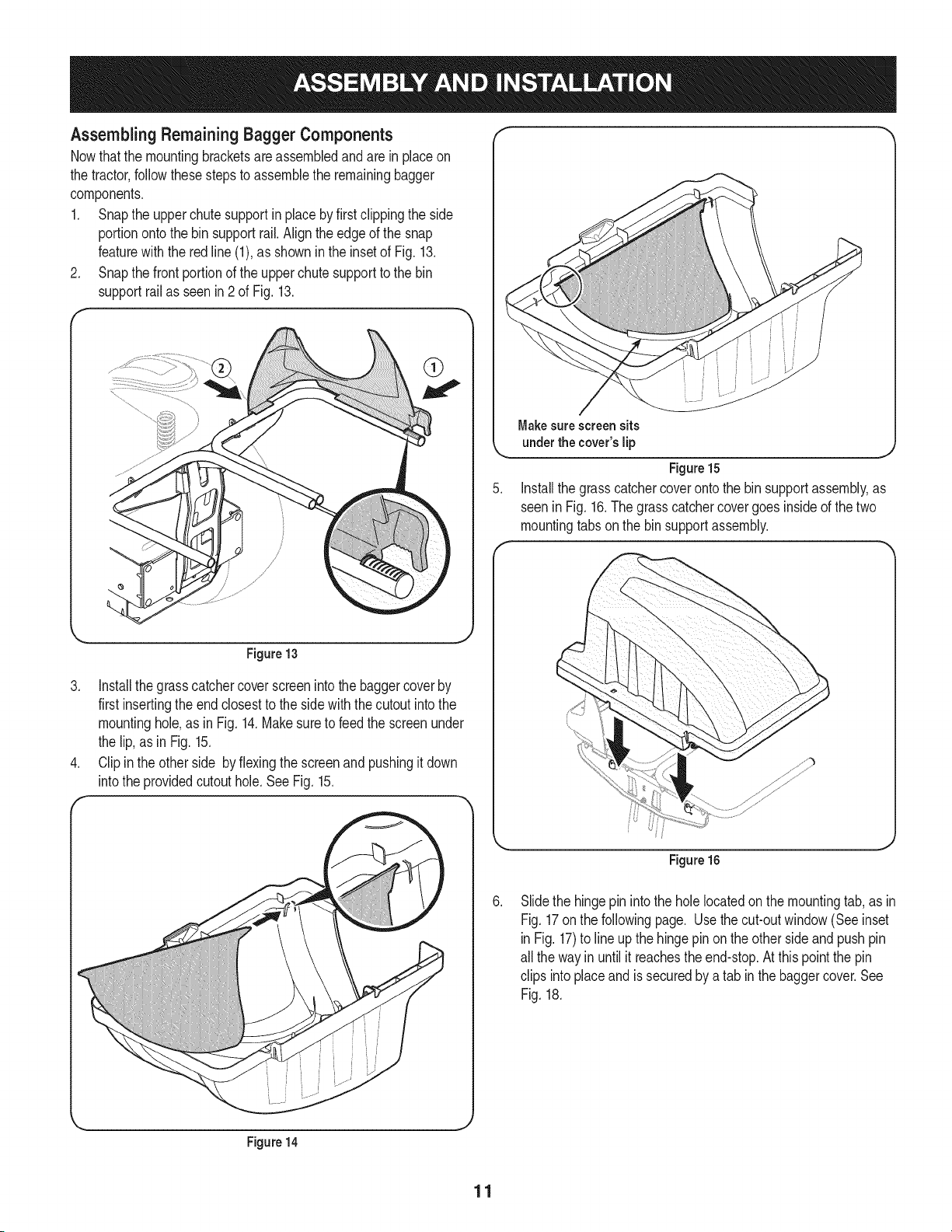
Assembling Remaining Bagger Components
Nowthatthe mountingbracketsare assembledand are inplaceon
the tractor,followthesestepsto assemblethe remainingbagger
components.
1. Snapthe upper chutesupportin placeby firstclippingthe side
portionontothe binsupportrail.Align theedgeof the snap
featurewith the redline (1),as shownin the insetof Fig.13.
2. Snapthe frontportionof the upperchute supportto the bin
supportrailas seenin2 of Fig. 13.
f
\
Figure13
3. Installthegrasscatchercoverscreenintothe baggercoverby
first insertingthe end closestto the sidewith thecutoutintothe
mountinghole,as inFig. 14.Makesureto feed the screenunder
the lip,as in Fig. 15.
4. Clipinthe otherside byflexingthescreenand pushingitdown
intothe providedcutouthole.See Fig. 15.
Figure14
Makesurescreensits
underthe cover'slip
Figure15
Installthe grass catchercoverontothe bin supportassembly,as
seenin Fig. 16.The grasscatchercovergoes insideof the two
mountingtabsonthe binsupportassembly.
Figure 16
Slidethe hingepin intothe holelocatedonthe mountingtab,as in
Fig.17onthe followingpage. Use thecut-outwindow(Seeinset
inFig. 17)to lineupthe hingepin on the otherside andpushpin
all the wayin until itreachesthe end-stop.At thispointthe pin
clips intoplaceand issecuredby a tab inthe baggercover.See
Fig.18.
11
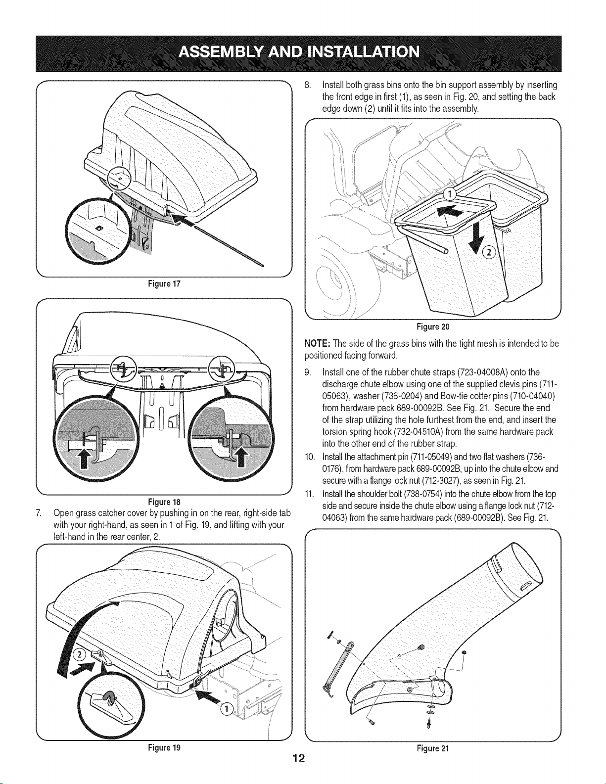
Figure17
J
Figure18
Opengrasscatchercoverby pushinginon the rear,right-sidetab
withyourright-hand,as seenin 1 of Fig. 19,andlifting withyour
left-handinthe rear center,2.
.
Installbothgrass bins ontothe binsupportassemblybyinserting
the front edge in first (1),as seen in Fig.20, andsettingthe back
edgedown(2) untilit fits intothe assembly.
/
Figure 20
NOTE: Theside of the grassbins withthetight meshis intendedto be
positionedfacingforward.
.
10.
11.
Installoneof the rubberchutestraps(723-04008A)ontothe
dischargechuteelbowusingone of the suppliedclevispins (711-
05063),washer(736-0204)and Bow-tiecotter pins(710-04040)
fromhardwarepack689-00092B.SeeFig. 21. Securetheend
of the straputilizingthe holefurthestfrom the end,and insertthe
torsionspringhook(732-04510A)fromthe samehardwarepack
into theother end of the rubberstrap.
Installtheattachmentpin(711-05049)andtwoflatwashers(736-
0176),fromhardwarepack689-00092B,upintothechuteelbowand
securewithaflangelocknut(712-3027),asseeninFig.21.
Installtheshoulderbolt(738-0754)intothechuteelbowfromthetop
sideandsecureinsidethechuteelbowusingaflangelocknut(712-
04063)fromthe samehardwarepack(689-00092B).SeeFig.21.
Figure 19
12
Figure 21
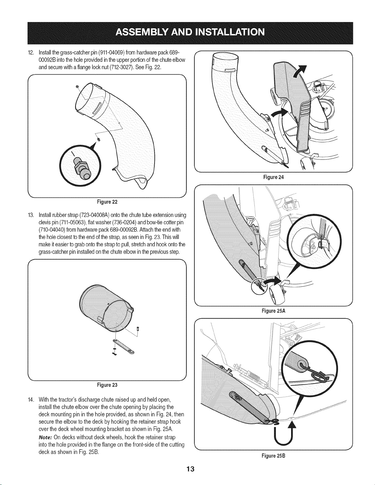
12. Installthegrass-catcherpin(911-04069)fromhardwarepack689-
00092Bintotheholeprovidedin theupperportionofthechuteelbow
andsecurewithaflangelocknut(712-3027).SeeFig.22.
f
Figure 24
13.
Figure 22
Installrubberstrap(723-04008A)ontothechutetubeextensionusing
clevispin(711-05063),flat washer(736-0204)andbow-tiecotterpin
(710-04040)fromhardwarepack689-00092B.Attachtheendwith
theholeclosestto theendofthe strap,asseenin Fig.23.Thiswill
makeit easierto grabontothestrapto pull,stretchandhookontothe
grass-catcherpininstalledonthechuteelbowinthepreviousstep.
Figure23
14.
Withthetractor'sdischargechute raisedup and held open,
installthe chuteelbowoverthe chuteopeningbyplacingthe
deckmountingpinin the holeprovided,as shownin Fig.24, then
securethe elbowto thedeckby hookingthe retainerstraphook
overthe deckwheelmountingbracketas shownin Fig.25A.
Note: Ondeckswithoutdeck wheels,hookthe retainerstrap
intothe holeprovidedin theflangeon thefront-sideof the cutting
deckas shownin Fig.25B.
13
Figure25A
Figure25B
J
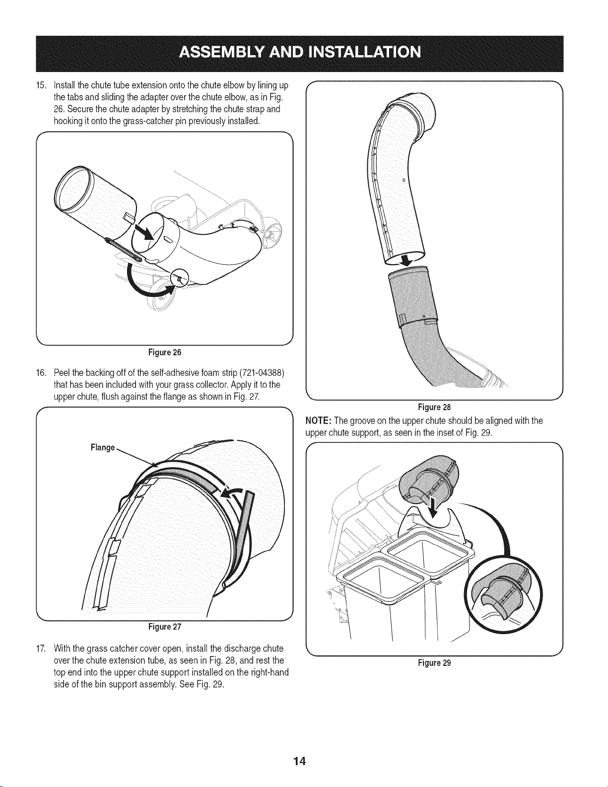
15.
16.
17.
Installthechute tubeextensionontothe chuteelbowby liningup
thetabs and slidingthe adapteroverthe chute elbow,as inFig.
26. Securethe chuteadapterby stretchingthe chute strapand
hookingit onto the grass-catcherpin previouslyinstalled.
Figure 26
Peelthe backingoff of the self-adhesivefoam strip (721-04388)
thathas beenincludedwith yourgrasscollector.Applyit to the
upperchute,flushagainstthe flangeas shownin Fig. 27.
Flange
I
Figure27
Withthe grass catchercoveropen, install the dischargechute
overthe chuteextensiontube,as seen in Fig. 28, and restthe
top end into the upperchute supportinstalledon the right-hand
side of the binsupportassembly.See Fig.29.
Figure28
NOTE: Thegrooveon the upperchute shouldbealignedwith the
upperchutesupport,as seenin theinsetof Fig.29.
Figure 29
14
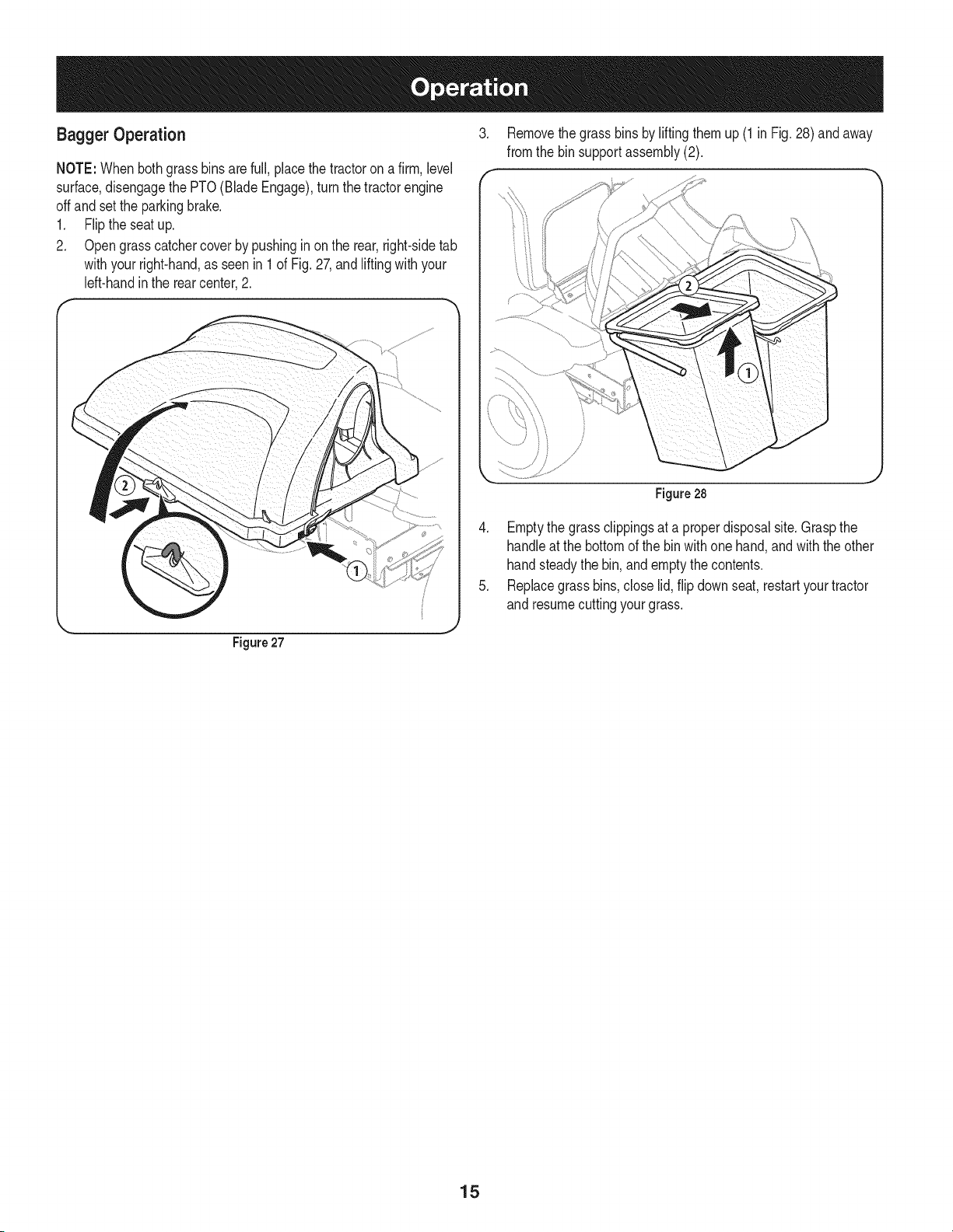
Bagger Operation 3.
f
NOTE:Whenbothgrassbinsare full, placethetractoron a firm, level
surface,disengagethe PTO(BladeEngage),turn the tractorengine
offand setthe parkingbrake.
1. Flipthe seat up.
2. Opengrasscatchercover by pushingin on the rear,right-sidetab
withyourright-hand,as seenin 1 of Fig. 27,and liftingwith your
left-handinthe rear center,2.
Removethe grass binsby liftingthem up (1 in Fig. 28) and away
fromthe bin supportassembly(2).
J
Figure27
Figure28
4. Emptythe grassclippingsat a properdisposalsite.Graspthe
handleat the bottomof the bin with one hand,andwith the other
handsteadythe bin, andemptythecontents.
5. Replacegrass bins,close lid, flip downseat,restartyourtractor
and resumecuttingyourgrass.
15
2
31
\
14
@
15
16

m
1
2
3
4
5
6
7
8
9
10
11
12
13
14
15
16
17
18
19
2O
21
22
23
24
25
26
27
28
29
30
31
32
33
34
35
36
37
38
39
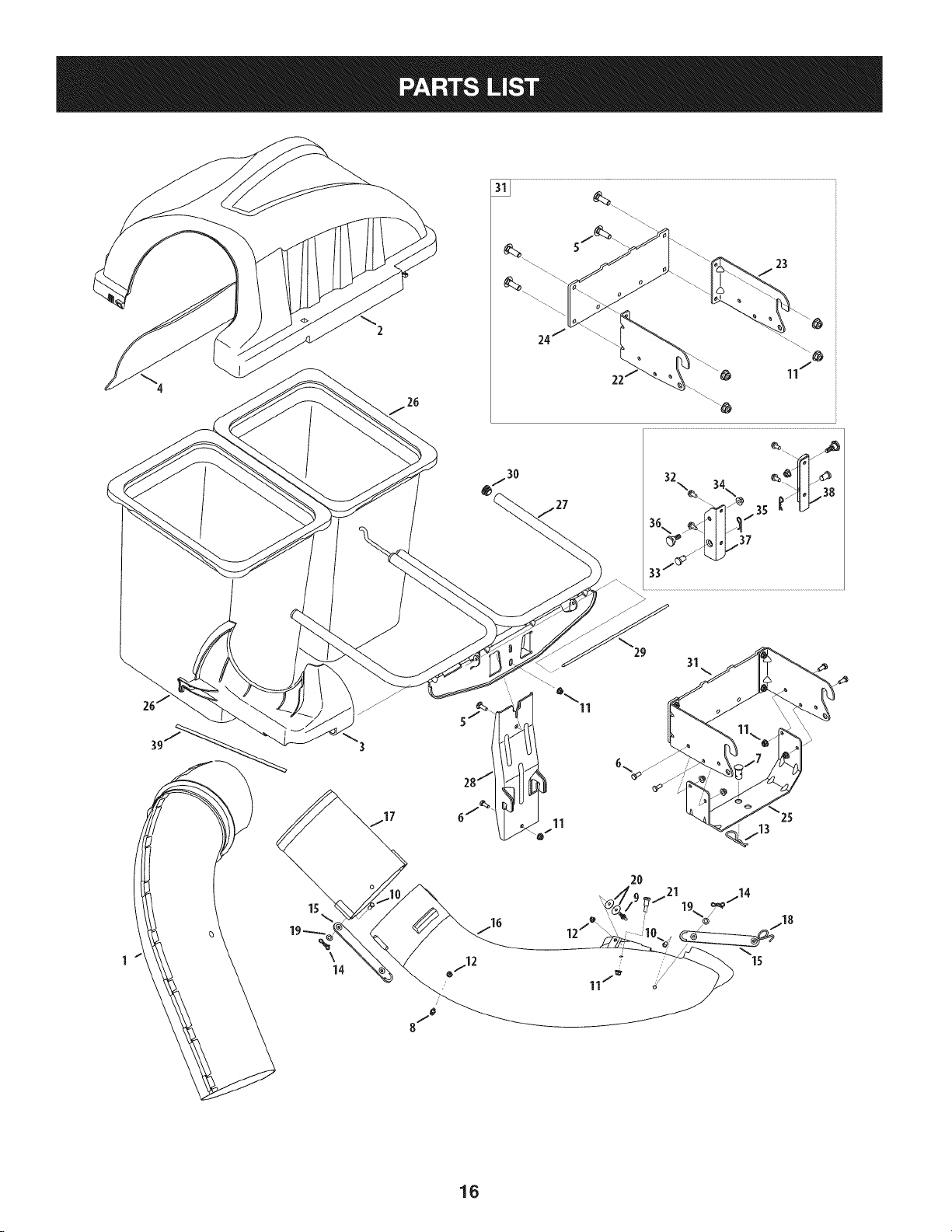
931-04291
931-04292
731-06497
731-06504
710-0276
710-3008
711-0309A
911-04069
711-05049
711-05063
712-04063
712-3027
714-0117
714-04040
723-04008A
731-06099B
731-06610
732-04510A
736-0204
736-0176
738-0754
N/A*
N/A*
N/A*
783-05887
964-04096A
683-04461A-0637
683-04519-0637
711-04988
735-0246A
689-00101
710-04484
711-0332
712-04065
914-0145
738-04267
783-05889A-0637
783-05890A-0637
721-04388
UpperChuteAssembly
DoubleBaggerCoverAssembly
UpperChuteSupport
BaggerCoverScreen
CarriageScrew,5/16-18x 1.00"
HexHeadScrew,5/16-18x .75"
ClevisPin, .62"Dia.
Grass-catcherPin, 1/4-20
AttachmentPin,1/4x 0.66 Lg.
ClevisPin,5/16x .75Lg.
FlangeLockNut,5/16-18
FlangeLockNut, 1/4-20
InternalCotterPin, .148x 3.00
Bow-TieCotterPin,72
ChuteStrap,6.00Lg.
BaggerDischargeChute,Elbow
BaggerChuteAdapter,7 In.
TorsionSpringHook
FiatWasher,.344x .62x .033
FiatWasher,.265x .938x .120
ShoulderScrew,.437x .54
MountingBracket,RH
MountingBracket,LH
UniversalMountingBracket
UniversalSupportBracket
Grass-bagAssembly
DoubleBagSupportAssembly
VerticalSupportBracket
CoverHingePin
EndPlug
MountingBracketKit (incl.ref.22, 23, 24)
TapScrew,5/16-18x .750
ClevisPin, .50x .78
FlangeLockNut,3/8-16
Click Pin,.092x 1.64Lg.
ShoulderScrew,.625x .412
MountingBracket,RH
MountingBracket,LH
Self-AdhesiveFoamStrip
*Availableas anassemblyonly orderRef.31
17

Craftsman Total Garantia
CraftsmanSiesteproductofalla debidoa un defectode materialo manode obra dentrode un aSoa partirde la fechadecompra,el retornoa
cualquierfiendaSearso cualquierotra Craftsmande salidaenlos EstadosUnidospara la sustituci6ngratuita.
EstagaranfiacubreQnicamentedefectosde materialy manode obra. Searsno pagar&por:
• Sustituci6ndelas bolsas,quesonfungiblesque puedenIlevara cabo apartir de la utilizaci6nnormalen el periodode
garanfia.
• Las reparacionesnecesariasa causade accidenteo el fracasoparaoperaro mantenerel productode acuerdocon todaslas
instruccionessuministradas.
Estagarantiaseaplicaa s61o90dias si esteproductoes utilizadocadavezcon finescomercialeso alquiler.
Estagaranfias61ose aplicamientrasesteproductose utilizaen los EstadosUnidos.
Estagaranfiale otorgaderechoslegalesespedficos,y ustedtambi_npuedetenerotrosderechosquevariande un estadoa otro.
Sears Brands ManagementCorporation., Hoffman Estates, IL 60179
© KCD IR LLC 18
Lapresenciadeeste sirnboloindicaque setrata de instrucciones
irnportantesde seguridadquese debenrespetarpara evitar
ponerenpeligrosu seguridadpersonaly/o materialy lade otras
personas.Leay siga todaslas instruccionesde este manualantes
de poneren funcionarnientoestarnAquina.Si no respetaestas
instruccionespodriaprovocarlesionespersonales.Cuandoveaeste
sirnbolo,ipresteatenci6na la advertencia!
PROPOSICION 65 DE CALIFORNIA
Elescapedel motordeesteproducto,algunosde suscornponentes
y algunoscornponentesdelvehiculocontieneno liberan sustancias
quirnicasqueelestadodeCaliforniaconsideraque puedenproducir
cancer,defectosde nacirnientouotros problernasreproductivos.
Losbornesde la bateriay los accesoriosalinescontienenplornoy
cornpuestosde plorno,sustanciasquirnicasque seg_nIo estableci-
do porel Estadode Californiacausancancery daSosen el sisterna
reproductivo.Ldveselas manos despu_sde estar en contacto
con estoscomponentes.
EstarnAquinarue construidapara seroperadadeacuerdocon
las reglasde seguridadcontenidasen este manual.AI igualque
concualquiertipo deequipo rnotorizado,un descuidoo error por
partedel operadorpuedeproducirlesionesgraves.EstarnAquina
es capazde arnputarrnanosy piesy dearrojarobjetoscon gran
fuerza.Deno respetarlas instruccionesde seguridadsiguientesse
puedenproducirlesionesgraveso larnuerte.
Su responsabilidad--Restrinja el usode esta rnAquina
rnotorizadaalas personasque lean,cornprendany respetenlas
advertenciase instruccionesqueaparecenen estemanualyen la
rnAquina.
iGUARDEESTASINSTRUCCIONES!
Fun¢ionamiento general
1. Lea, comprenda y respete todas las instrucciones que figuran
en el equipo yen los manuales antes de intentar armarlo y
hacerlo funcionar. Guarde este manual en un lugar seguro
para consultas futuras y peri6dicas, asi como para solicitar
repuestos.
2. Para ayudar a evitar una lesi6n pot contacto con las cuchillas
o con un objeto que sea arrojado, mantenga alas personas
que observan, a los ayudantes, ni_os y mascotas alejados a no
menos de 25 metros de la m_quina mientras est& funcionando.
Detenga la m&quina si alguien entra en la zona.
3. Revise minuciosamente el _irea donde se va a usar el equipo.
Retire todas las piedras, palos, cables, huesos, juguetes y otros
objetos extra6os que podrian set recogidos y arrojados por la
acci6n de las cuchillas. Los objetos arrojados por la m&quina
pueden causar lesiones graves.
4. Para protegerse los ojos, utilice siempre galas o lentes de
seguridad mientras opera la m&quina o mientras la ajusta
o repara. Los objetos arrojados que rebotan pueden causar
lesiones oculares graves.
5. Nunca opere la cortadora de c_sped sin tenet bien colocada
la cubierta de descarga o el colector de c_sped. Si falta o
est_ da6ada la cubierta de descarga o un componente del
accesorio embolsador puede resultar en lesiones por contacto
con la cuchilla o con objetos arrojados.
6. No ponga las manos ni los pies cerca de las piezas rotatorias ni
debajo de la plataforma de corte. El contacto con las cuchillas
puede resultar en la amputaci6n de una mano o pie.
7. Apague el motor de la cortadora de c_sped y espere que
las cuchillas se detengan totalmente antes de desbloquear
la abertura de descarga de la cortadora o las piezas de la
embolsadora.
8. Reduzca la velocidad antes de girar. Opere la m&quina de
forma pareja. Evite el funcionamiento err_itico y la velocidad
excesiva. Tenga en cuenta que el accesorio colector de c_sped
puede afectar las caracteristicas de manejo de su cortadora.
Fundonamiento en pendientes
Las pendientes son un factor importante en los accidentes
ocasionados pot p_rdida de control y vuelcos que pueden causar
lesiones graves e incluso la muerte. Los accesorios tambien pueden
afectar la estabilidad de la m&quina. La operaci6n en pendiente
requiere mayor precauci6n.
Para seguridad, use el medidor de pendientes que se incluye como
parte de este manual para estimar el _ingulo de la pendiente antes
de hacer funcionar la m_iquina en una zona inclinada. Si la pendiente
es mayor a 10 grados en el medidor, no opere la cortadora con el
accesorio embolsador en ese sector, pues podria causar lesiones
graves.
HagaIo siguiente:
1. Corte hacia arriba y abajo de las pendientes, no en forma
transversal. Tenga sumo cuidado al cambiar de direcci6n en
una pendiente.
2. Est_ atento a los hoyos, surcos, baches, rocas, u otros objetos
ocultos. El terreno desnivelado puede voltear la m&quina. El
pasto alto puede ocultar obst_iculos.
3. Conduzca a baja velocidad. Elija una velocidad Io
suficientemente baja como para no tener que detenerse
o cambiar de marcha mientras est,1 en la pendiente. Los
neum_ticos pueden perder tracci6n en las pendientes aun
cuando los frenos funcionen correctamente. Mantenga
la m&quina siempre en velocidad cuando desciende una
pendiente, para poder frenar con el motor.
19
4. Siga las recomendaciones del fabricante sobre pesos y
contrapesos de las ruedas, para mejorar la estabilidad.
5. Haga que todos los movimientos en las pendientes sean
lentos y graduales. No cambie repentinamente la velocidad
ni la direcci6n. Un frenado o cambio de velocidad repentinos
pueden causar que el frente de la m_quina se levante y d6 una
voltereta hacia atr_s, Io que podria causar lesiones graves.
6. Evite arrancar o detenerse en una pendiente. Si los neum_ticos
pierden tracci6n, desenganche las cuchillas y descienda
lentamente la pendiente.
No haga I0siguiente:
I. No gire en una pendiente a menos que sea imprescindible. De
ser posible, gire lenta y gradualmente cuesta abajo.
2. No corte el c_sped cerca de barrancos, zanjas o terraplenes. La
cortadora de c_sped podria volcarse repentinamente si una de
las ruedas estuviera sobre el borde de un acantilado o zanja, o
si un borde se desmoronara.
3. No intente estabilizar la m_quina poniendo el pie en el suelo.
4. No utilice un colector de c_sped en pendientes empinadas.
5. No corte el c_sped humedo. Una reducci6n en tracci6n puede
causar derrapes.
Servid0 general
I. Antes de limpiar, reparar o inspeccionar la m_quina,
compruebe que las cuchillas y todas las piezas m6viles se
hayan detenido. Desconecte el cable de la bujia y p6ngalo
haciendo masa contra el motor para evitar que arranque
accidentalmente.
2. Mantenga todas las tuercas, pernos y tornillos bien ajustados
para asegurarse de que el equipo est_ en condiciones seguras
de operaci6n.
3. Nunca intente violar el sistema de bloqueo de seguridad u
otros mecanismos de seguridad de la cortadora. Controle
peri6dicamente que funcionan correctamente.
4. No intente nunca hacer ajustes o reparaciones a la cortadora
mientras el motor est_ en marcha.
5. Los componentes del colector de c6sped y la cubierta de
descarga est_n sujetos a desgaste y daffos que podrian dejar
expuestas piezas que se mueven o permitir que se arrojen
objetos. Para proteger su seguridad, verifique frecuentemente
todos los componentes y reempl_celos inmediatamente
0nicamente con piezas de los fabricantes del equipo original
(O.E.M.) indicados en este manual. El uso de piezas que no
cumplen con las especificaciones del equipo original puede
resultar en rendimiento inadecuado y puede poner en peligro
la seguridad.
6. Mantenga o reemplace las etiquetas de seguridad y de
instrucciones seg0n sea necesario.
Simbolosde segufidad
En esta p_gina se presentan y describen los simbolos de seguridad que pueden aparecer en este producto. Lea, entienda y cumpla todas las
instrucciones incluidas en la m_quina antes de intentar armarla y utilizarla.
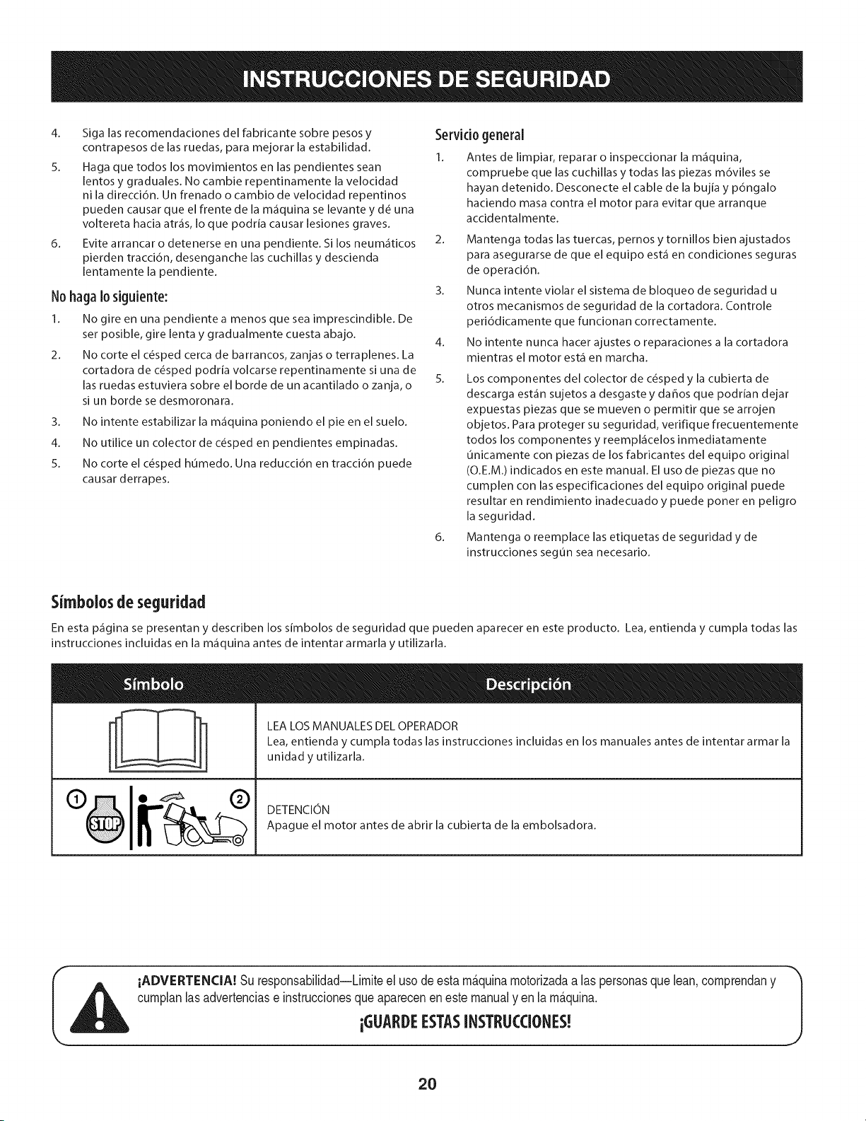
LEA LOS MANUALES DEL OPERADOR
Lea, entienda y cumpla todas las instrucciones incluidas en los manuales antes de intentar armar la
unidad y utilizarla.
DETENCION
Apague el motor antes de abrir la cubierta de la embolsadora.
iADVERTENCIA! Su responsabilidad--Limiteel usodeesta m_.quinamotorizadaalas personasque lean,comprendany
cumplanlasadvertenciase instruccionesque aparecenen este manualyen la m_.quina.
iGUARDEESTASINSTRLICCIONES!
2O
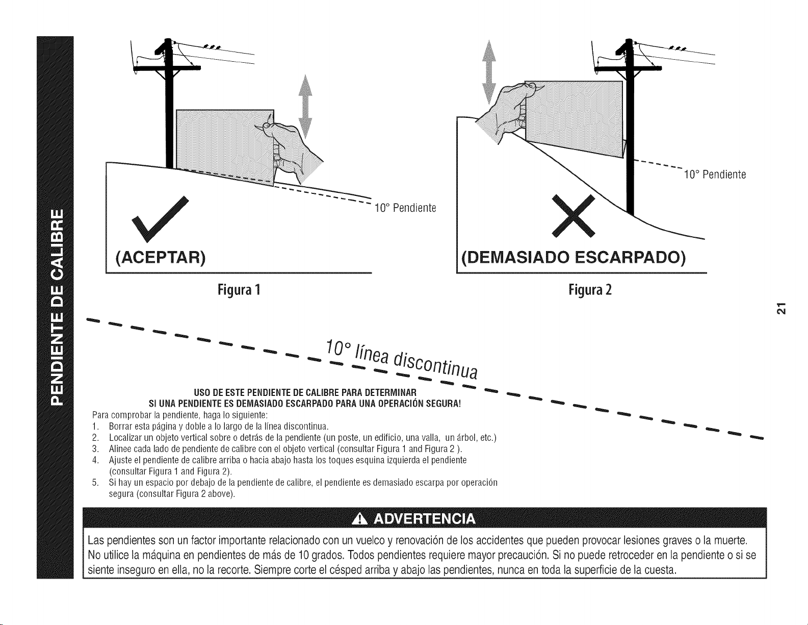
(ACEPTAR)
Figura1
"" 10 ° Pendiente
10° Pendiente
(DEiVIASlADO ESCARPADO)
Figura2
0oI[nea
- - " "" - _ .-...diSC°ntinua
US0 DEESTEPENDIENTEDECALIBREPARADETERiVIINAR
SI UNAPENDiENTEESDEIV1ASiADOESCARPADOPARAUNAOPERACi(_NSEGURA!
Paracomprobarlapendiente,hagaIosiguiente:
1. Borrarestap_.ginay doble a Io largodelalineadiscontinua.
2.
3.
4.
Localizarun objetoverticalsobreo detrJ.sde la pendiente(un poste,un edificio,unavalla, un _.rbol,etc.)
Alineecadaladodependientedecalibrecon elobjetovertical(consultarFigura1 andFigura2 ).
Ajusteel pendientedecalibrearriba o haciaabajo hastalos toquesesquinaizquierdael pendiente
(consultarFigura1andFigura2).
Sihayun espaciopor debajodela pendientedecalibre,el pendientees demasiadoescarpapor operaciOn
segura(consultarFigura2 above).
Las pendientesson un factor importante relacionadocon un vuelco y renovaci6nde los accidentes que pueden provocar lesiones graves o la muerte.
No utilice la m_.quinaen pendientes de m_.sde 10grados. Todos pendientesrequiere mayor precauci6n. Si no puede retroceder en la pendiente o si se
siente inseguro en ella, no la recorte. Siempre corte el cesped arriba y abajo laspendientes, nunca en toda la superficie de la cuesta.
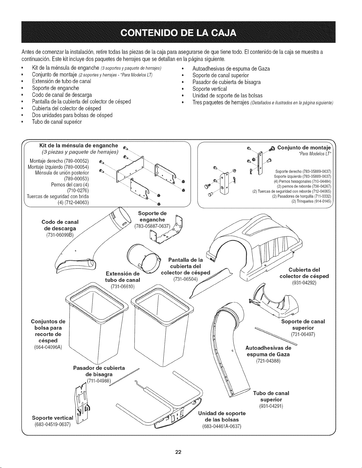
Antesdecomenzarla instalaci6n,retiretodas las piezasdela cajaparaasegurarsedequefienetodo, El contenidode la cajase muestraa
confinuad6n,Estekit induyedos paquetesde herrajesque se detallanen lap_.ginasiguiente,
• Kit de la m_nsulade enganche(3soportesy paquete de herrajes)
Conjuntode montaje(2soportesyherrajes- *ParaModelosLT)
• Extensidndetubode canal
• Soportede enganche
• Codode canalde descarga
• Pantalladela cubiertadelcolectorde c_sped
• Cubiertadelcolectorde cesped
• Dosunidadesparabolsasdecesped
• Tubode canalsuperior
• AutoadhesivasdeespumadeGaza
• Soportede canalsuperior
• Pasadorde cubiertade bisagra
Soportevertical
• Unidadde soportede las bolsas
Trespaquetesde herrajes(Detalladose ilustradosen lapagina siguiente)
Kit de la m_nsula de enganche
(3 piezas y paquete de herrajes) _\_
Montajederecho(789-00052)
Montajeizquierdo(789-00054)
Mensuladeuni6n posterior
(789-00053)
Pernosdel caro (4)
(710-0276)
Tuercasde seguridadcon brida
(4) (712-04063)
Codo de canal
de descarga
(731-06099B)
Soporte de
enganche
(783-05_
Pantalla de la
tubo de canal (731-06504)
(731-06610)
_ j_ Conjunto de montaje _
*ParaModelos LT*
__ Soportederecho (783-05889-0637)
Soporte izquierdo(783-05889-0637)
(4) Pernos hexagonales (710-04484)
(2) pernos de reborde (738-04267)
(2)Tuercas de seguridad con reborde (712-04065)
(2) Pasadores de horquilla (711-0332)
(2) Trinquetes(914-014_
Cubierta del
colector de c_sped
(931-04292)
Conjuntos de
bolsa para
recorte de
c_sped
(664-04096A) _
Pasador de cubierta_
de bisagra _ _,._
_,(711-04988)_" _.. "_
Soportevertical f37" aelasbolsas
(683-04519-0637) _._,'_'_ (683-04461A-0637)
Soporte de canal
_7_3 superi°r
1-06497)
Autoadhesivas de
espuma de Gaza
(721-04388)
Tubo de canal
superior
(931-04291)
J
22
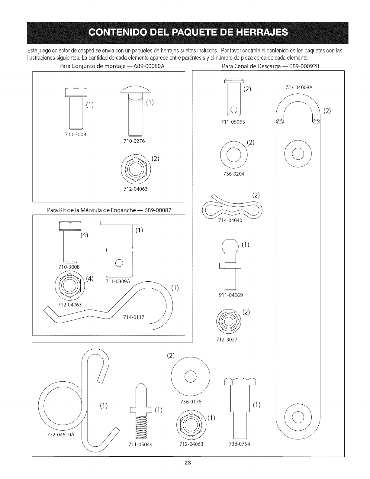
Estejuegocolectorde c_spedse enviacon un paquetesde herrajessueltosincluidos. Porfavor controleel contenidode los paquetescon las
ilustracionessiguientes.Lacantidadde cadaelementoapareceentrepar_ntesisy el n0merodepiezacerca de cadaelemento.
ParaConjunto de montaje -- 689-00080A ParaCanal de Descarga -- 689-00092B
1) (1)
710-3008
710-0276
712-04063
Para Kit de la M_nsula de Enganche -- 689-00087
4)
710-3008
(4)
712-04063
I
©
711-0309A
I
(1)
714-0117
732-04510A
(1)
711-05049
1)
(1)
736-0176
712-04063
(2) 723-04008
711-05063
(2)
736-0204
(2)
714-04040
[_(1)
911-04069
(2)
712-3027
)
738-0754
(2)
23
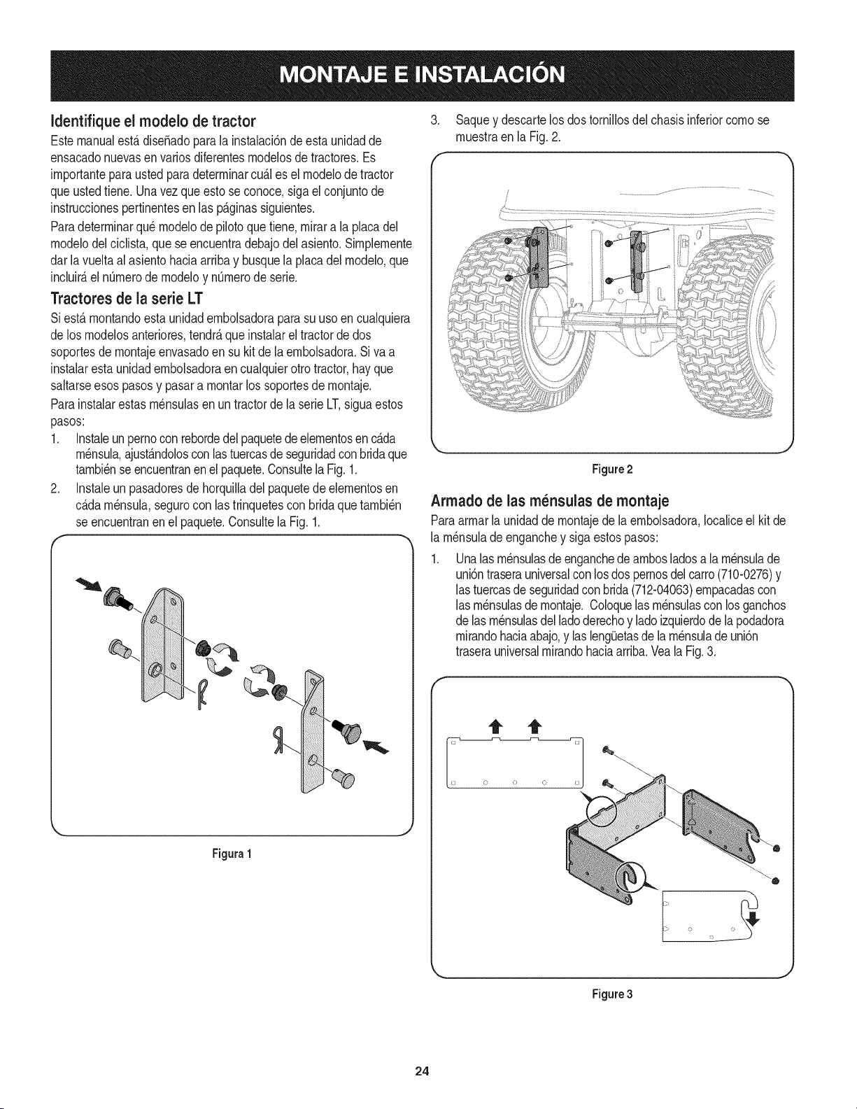
Identifique el rnodelo de tractor
Estemanualest,.dise_adoparala instalaci6ndeesta unidadde
ensacadonuevasen variosdiferentesrnodelosde tractores.Es
irnportanteparaustedparadeterrninarcu_.les el rnodelode tractor
queustedtiene.Unavezqueestose conoce,sigael conjuntode
instruccionespertinentesen las p_.ginassiguientes.
Paradeterrninarqu_rnodelodepilotoquetiene,rnirara la placadel
rnodelodelciclista,que seencuentradebajodelasiento.Sirnplernente
darla vueltaal asientohaciaarribay busquela placadel rnodelo,que
incluir_,el nOrnerode rnodeloy nOrnerode serie.
Tractores de la serie LT
Siest,. rnontandoestaunidadernbolsadorapara su usoen cualquiera
de losrnodelosanteriores,tendr_,que instalarel tractorde dos
soportesde rnontajeenvasadoen su kitde la ernbolsadora.Si va a
instalarestaunidadernbolsadoraencualquierotto tractor,hayque
saltarseesospasosy pasara rnontarlos soportesde rnontaje.
Parainstalarestas rn_nsulasen un tractorde la serieLT,siguaestos
pasos:
1. Instaleun pernoconrebordedelpaquetedeelernentosen c_.da
rn_nsula,ajust_.ndoloscon lastuercasde seguridadcon bridaque
tarnbi_nse encuentranen el paquete.Consultela Fig.1.
2. Instaleunpasadoresdehorquilladelpaquetedeelernentosen
c_.darn_nsula,segurocon las trinquetescon bridaque tarnbi_n
se encuentranen el paquete.Consultela Fig.1.
Figura1
3. Saquey descartelos dostornillosdel chasisinferiorcornose
rnuestraen la Fig.2.
f
Figure2
Arrnadode las rn_nsulas de montaje
Paraarrnarla unidadde rnontajedela ernbolsadora,Iocaliceel kit de
la rn_nsulade enganchey siga estospasos:
Unalas rnensulasde enganchede arnbosladosa la rnensulade
uni6ntraserauniversalconlosdos pernosdelcarro(710-0276)y
las tuercasde seguridadcon brida(712-04063)ernpacadascon
las rn_nsulasde rnontaje.Coloquelas rn_nsulascon losganchos
de lasrn_nsulasdel ladoderechoy ladoizquierdodela podadora
rnirandohaciaabajo,y las leng_Jetasde la rn_nsulade uni6n
traserauniversalrnirandohaciaarriba.Veala Fig.3.
Figure3
24
Nora:Estaunidaddelarn_nsulade rnontajeuniversalest,.dise_adao
parafuncionarconotrosaccesorios,cornoeseljuegode contrapesos
quese usajuntoconla cuchillaparanieveo el accesorioquitanieve.
Utilicelainforrnaci6ndecontactode la tapadeestemanual,o
cornuniqueseconlatiendadondeadquiri6el equipo,paraobtenerrn_.s
inforrnaci6nsobrelosaccesoriosdisponiblesparasutractorenparticular.
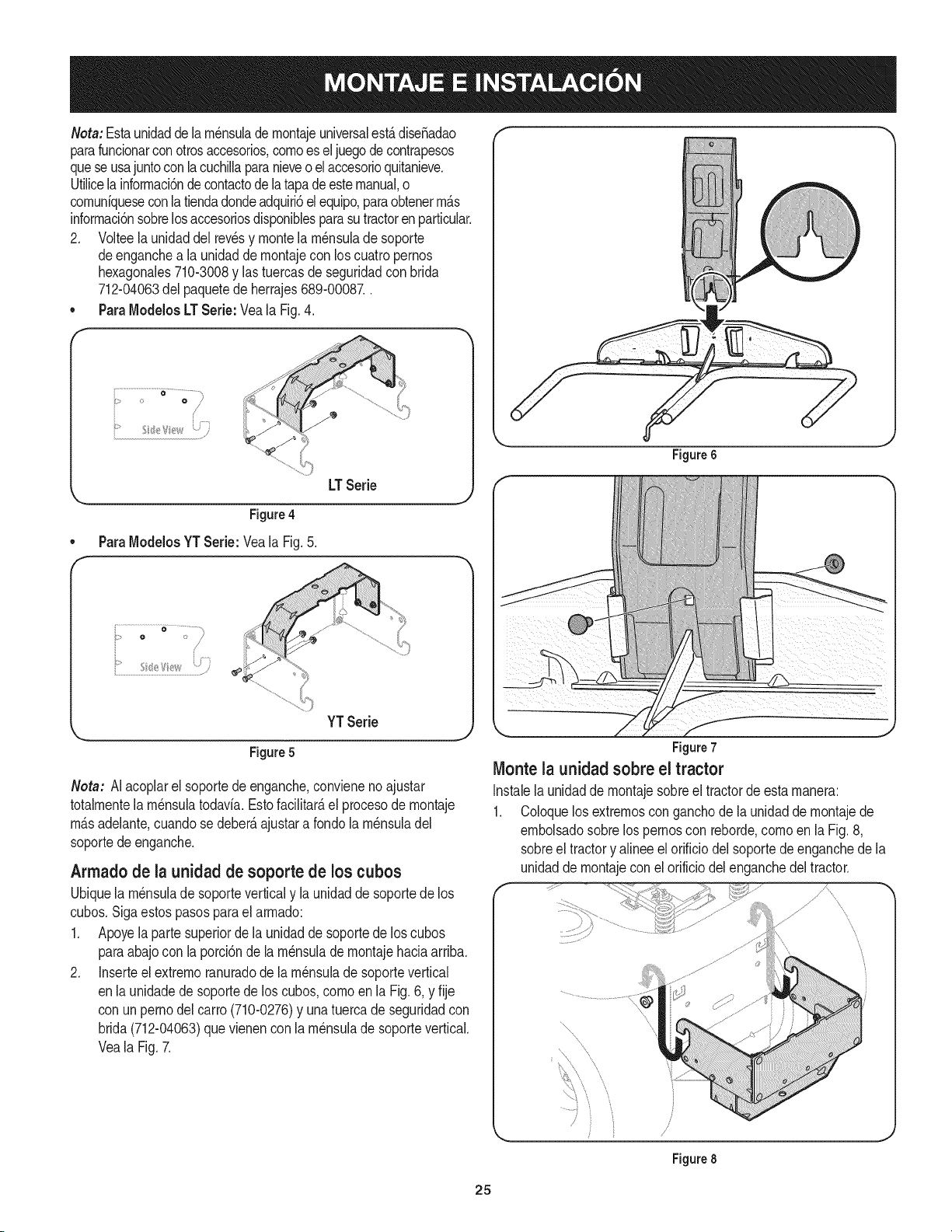
2. Volteela unidaddel revesy montela rn_nsulade soporte
deenganchea la unidaddernontajecon loscuatro pernos
hexagonales710-3008y lastuercasdeseguridadcon brida
712-04063del paquetedeherrajes689-00087..
• ParaModelosLTSerie: Veala Fig.4.
.j,:¢/J_
o__ •................_
LTSerie
Figure4
• ParaModelosYT Sede: Yeala Fig.5.
f
k,_ YT Serie
Figure5
Nora: AIacoplarel soportedeenganche,convienenoajustar
totalrnentelarn_nsulatodavia.Estofacilitate,el procesode rnontaje
rn_.sadelante,cuandose deber_,ajustara rondola rn_nsuladel
soportedeenganche.
Armado de la unidad de soporte de los cubos
Ubiquela rn_nsulade soporteverticaly la unidadde soportedelos
cubos.Sigaestos pasosparael arrnado:
1. Apoyela parte superiorde la unidadde soportede los cubos
paraabajocon la porci6nde la rn_nsulade rnontajehaciaarriba.
2. Inserteel extrernoranuradode la rn_nsulade soportevertical
enla unidadedesoportede los cubos,cornoenla Fig.6, y fije
con un pernodel carro(710-0276)y unatuercade seguridadcon
brida(712-04063)quevienenconla rn_nsulade soportevertical.
Veala Fig.7.
Figure 6
Figure7
Monte la unidad sobre el tractor
Instalela unidaddernontajesobreel tractorde esta rnanera:
1. Coloquelosextrernosconganchode la unidadde rnontajede
ernbolsadosobrelos pernoscon reborde,cornoenla Fig.8,
sobreel tractory alineeel orificiodel soportedeenganchede la
unidadde rnontajeconel orificiodel enganchedel tractor.
....s
................................................
'x
\
Figure 8
25
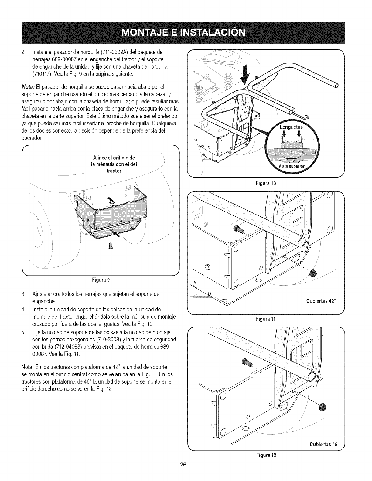
.
Instaleel pasadorde horquilla(711-0309A)del paquetede
herrajes689-00087enel enganchedeltractory el soporte
de enganchede la unidady fije con una chavetade horquilla
(710117).Veala Fig.9 en la p_.ginasiguiente.
Neta: El pasadorde horquillase puedepasarhaciaabajopot el
soportede engancheusandoel orificiom_.scercanoa lacabeza,y
asegurarloporabajocon la chavetade horquilla;o puede resultarm_.s
f_.cilpasarlohaciaarriba por la placade enganchey asegurarlocon la
chavetaen laparte superior.EsteOltimom_todosueleser el preferido
ya que puede serm_.sf_.cilinsertarel brochede horquilla.Cualquiera
de los doses correcto,la decisi6ndependede la preferenciadel
operador.
j
..............J
4
Alineeel orificio de
lam_nsulaconeldel
tractor ...............
iiiiiilliiiiii!iiiiiii! !' i i' iiiiiiiiiiliiilif!ii
.....i_iiiiii!_ii!i_!ili!iiiiiiiiii!i_iiiiililiiii!iiiiiiiii_iiii_iiii_ii_ii_ii_iiiiiii_iiiiiiii!i!i'_
f
,/
/
/
Figura9
3. Ajusteahoratodoslos herrajesque sujetanel soportede
enganche.
4. Instalela unidadde soportede las bolsasenla unidadde
montajedeltractorenganch_.ndolosobrela m_nsulade montaje
cruzadoporfuerade lasdos leng(Jetas.Veala Fig. 10.
5. Fijela unidadde soportede las bolsasa la unidadde montaje
con los pernoshexagonales(710-3008)y la tuercade seguridad
con brida (712-04063)provistaen el paquetede herrajes689-
00087.Veala Fig.11.
Nota:En lostractorescon plataformade 42" la unidadde soporte
se montaen el orificio centralcornoseve arribaen la Fig. 11.En los
tractorescon plataformade 46"la unidadde soportese montaen el
orificioderechocomose ve en la Fig. 12.
Figura 10
Figura 11
Figura 12
Cubiertas 42"
Cubiertas 46"
26
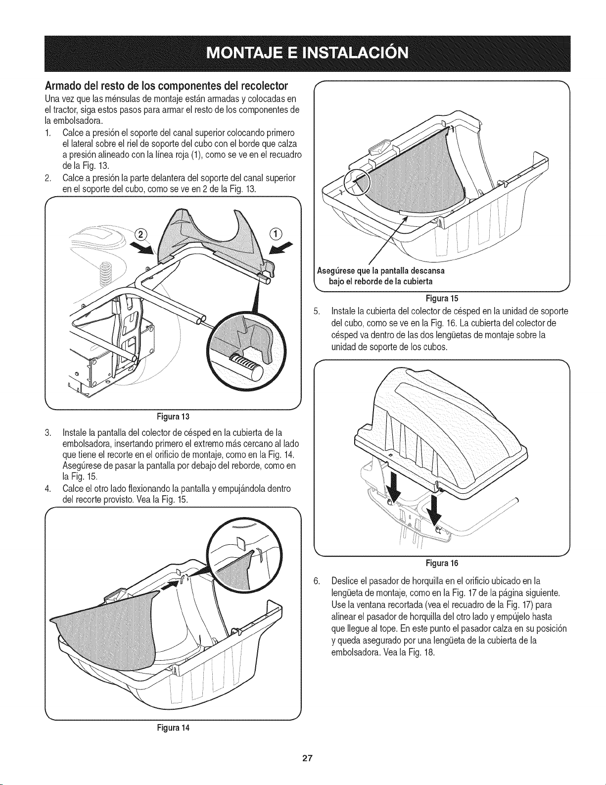
Armado del resto de los componentes dei recolector
Unavez que las rn_nsulasdernontajeest_.narmadasy colocadasen
el tractor,sigaestos pasosparaarrnarel restode los cornponentesde
la ernbolsadora.
1. Calcea presi6nel soportedelcanal superiorcolocandoprirnero
el lateralsobreel riel de soportedel cubocon el hordequecalza
a presi6nalineadocon la linea roja (1),cornose ve en el recuadro
dela Fig.13.
2. Calcea presi6nlapartedelanteradel soportedelcanalsuperior
enel soportedelcubo,cornoseve en2 de la Fig.13.
F *"
Figura13
3. Instalelapantalladel colectorde c_speden la cubiertade la
ernbolsadora,insertandoprirneroel extrernorn_.scercanoal lado
quetieneel recorteen el orificiode rnontaje,cornoen la Fig. 14.
AsegOresede pasarla pantallapordebajodel reborde,cornoen
la Fig.15.
4. Calceel otro ladoflexionandola pantallay ernpuj_.ndoladentro
del recorteprovisto.Veala Fig. 15.
f
Aseg_reseque la pantalladescansa
bajoel rebordedelacubierta
Figura15
5. Instalela cubiertadel colectorde c_speden la unidadde soporte
del cubo,cornoseve en la Fig.16.La cubiertadel colectorde
cespedva dentrode lasdos leng_Jetasde rnontajesobrela
unidadde soportede loscubos.
Figura14
Figura 16
Desliceel pasadordehorquillaenel orificioubicadoen la
lengiJetade rnontaje,cornoen la Fig.17de la p_.ginasiguiente.
Usela ventanarecortada(veael recuadrode la Fig. 17)para
alinearel pasadorde horquilladel otrolado y ernpOjelohasta
que Ileguealtope.Enestepuntoel pasadorcalzaen su posici6n
y quedaaseguradoporuna leng(Jetade la cubiertade la
ernbolsadora.Veala Fig.18.
27
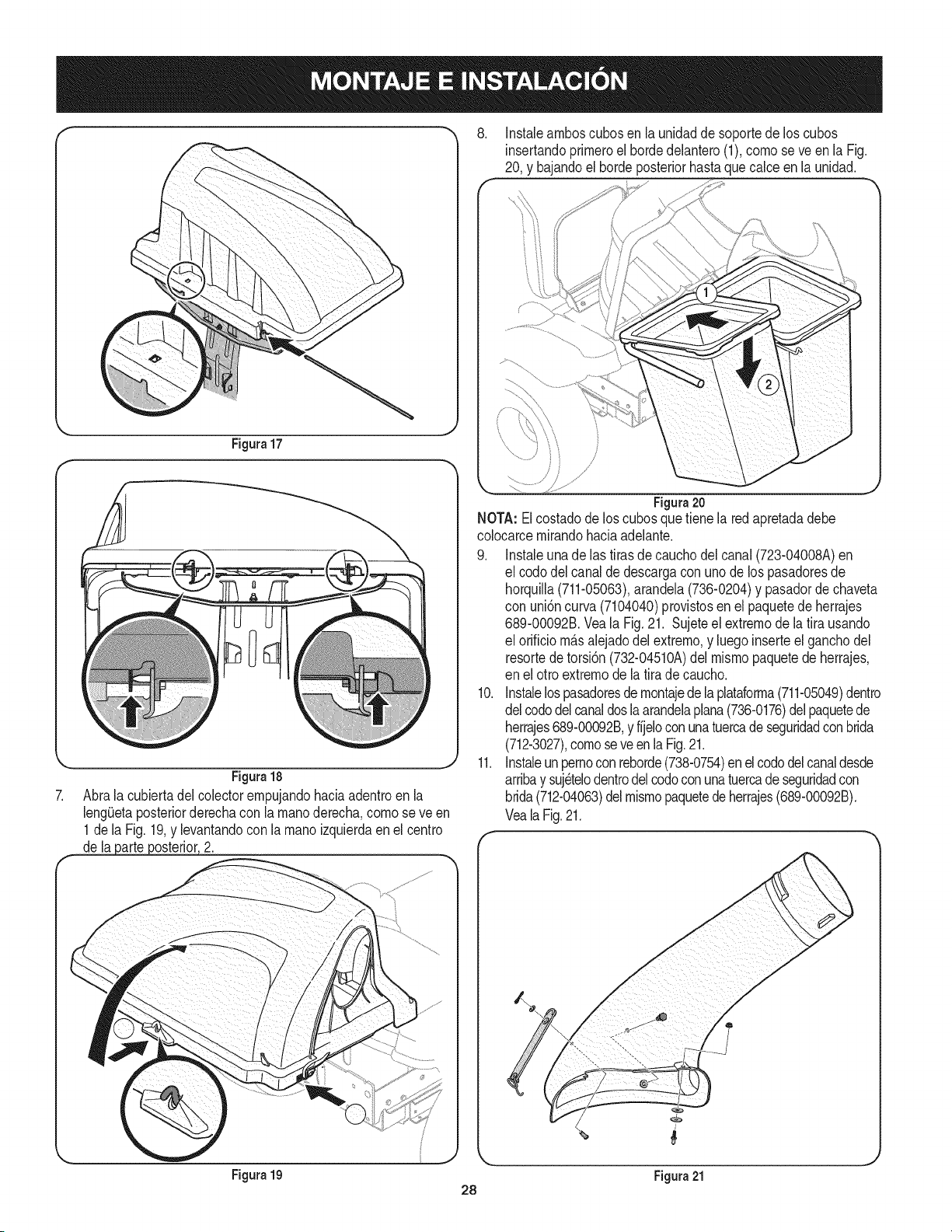
Figura17
Figura18
7. Abrala cubiertadel colectorempujandohaciaadentroen la
lengiJetaposteriorderechacon lamanoderecha,como se ve en
1de la Fig.19,y levantandocon la manoizquierdaenel centro
de lapa[t# poste[io[,2.
,
Instaleamboscubosenla unidadde soportedelos cubos
insertandoprirneroel hordedelantero(1),comose ve en la Fig.
20, y bajandoel hordeposteriorhastaquecalceen la unidad.
Figura20
NOTA:El costadode los cubosquetiene la red apretadadebe
colocarcemirandohaciaadelante.
9. Instaleuna de las tirasde cauchodelcanal (723-04008A)en
el codo del canalde descargacon unode los pasadoresde
horquilla(711-05063),arandela(736-0204)y pasadordechaveta
con uni6ncurva(7104040)provistosen el paquetede herrajes
689-00092B.Veala Fig.21. Sujeteel extremode la tira usando
el orificiom_.salejadodel extrerno,y luegoinserteel ganchodel
resortedetorsi6n(732-04510A)del mismopaquetede herrajes,
en el otroextremode la tirade caucho.
10. Instalelospasadoresde rnontajede la plataforma(711-05049)dentro
delcododelcanaldosla arandelaplana(736-0176)delpaquetede
herrajes689-00092B,y fijeloconunatuercadeseguridadconbrida
(712-3027),comoseve en la Fig.21.
11. Instaleun pernoconreborde(738-0754)en elcododelcanaldesde
arribay suj_telodentrodelcodoconunatuercadeseguridadcon
brida(712-04063)delmismopaquetede herrajes(689-00092B).
VealaFig.21.
Figura 19 Figura 21
28
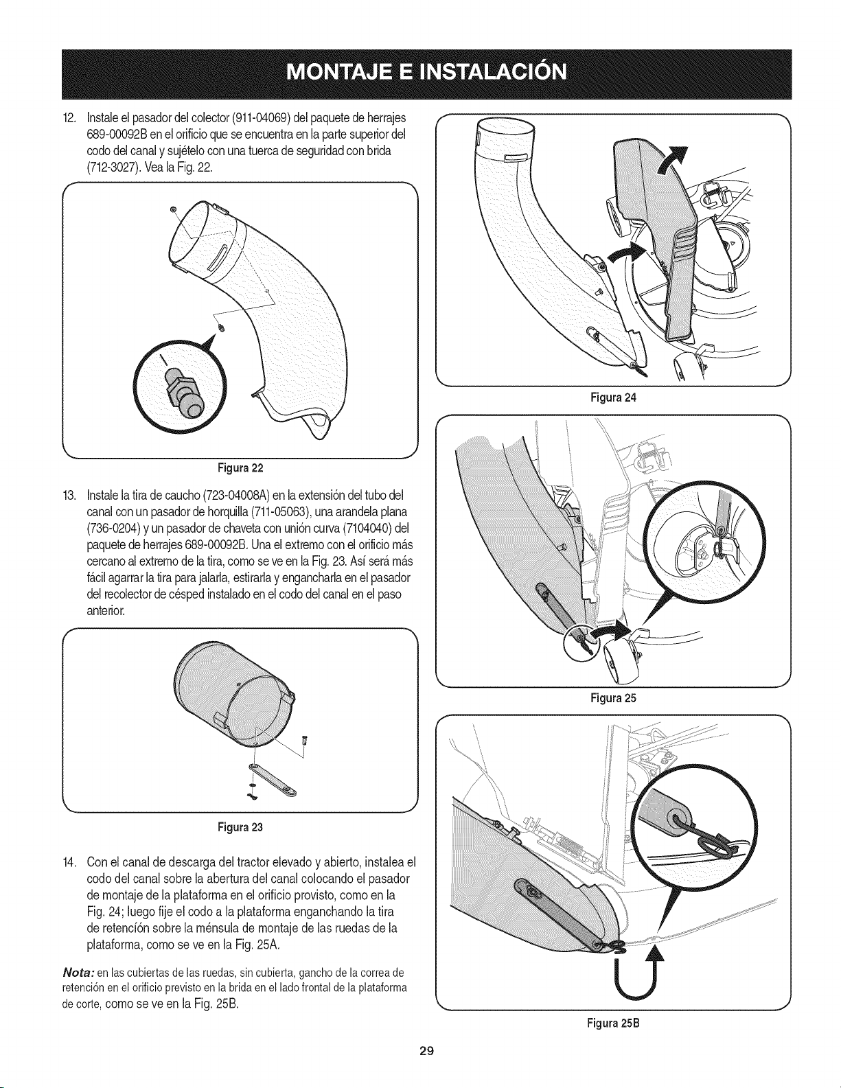
Instaleelpasadordelcolector(911-04069)delpaquetede herrajes
689-00092Ben el orificioque seencuentraen la partesuperiordel
cododelcanaly suj_teloconunatuercade seguridadconbrida
(712-3027).VealaFig.22.
,. j
Figura22
13.
InstalelaIra decaucho(723-04008A)en la extensi6ndeltubodel
canalconun pasadordehorquilla(711-05063),unaarandelaplana
(736-0204)y unpasadordechavetaconuni6ncurva(7104040)del
paquetedeherrajes689-00092B.Unaelextrernoconel orilciom_.s
cercanoalextrernodelaIra, comoseve enla Fig.23.Asi ser_.m_.s
f_.cilagarrarla Ira parajalarla,estirarlay engancharlaenel pasador
delrecolectordecespedinstaladoenelcododelcanalenel paso
anterior.
Figura23
14.
Conel canaldedescargadel tractorelevadoy abierto,instaleael
cododel canal sobrelaaberturadel canalcolocandoel pasador
demontajede laplataformaen elorificio provisto,comoenla
Fig.24; luegofije el codoa la plataformaenganchandola tira
de retenci6nsobrela m_nsulade montajede las ruedasde la
plataforma,comose ve enla Fig.25A.
Nora: en lascubiertasde lasruedas,sin cubierta,ganchode la correade
retenci6nen el orificioprevistoen la bridaen el ladofrontalde la plataforma
de corte, como se ve en la Fig. 25B.
Figura25
Figura25B
J
29
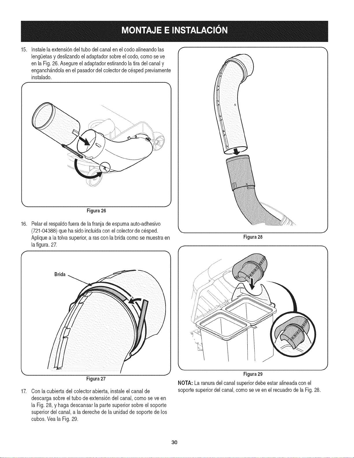
15. Instalela extensi6ndel tubo delcanalen el codoalineandolas
lengQetasy deslizandoel adaptadorsobreel codo,como se ve
en laFig.26. Asegureel adaptadorestirandola tira del canaly
enganch_.ndolaenel pasadordelcolectorde cespedpreviamente
instalado.
Figura 26
16. Pelarel respaldofuerade la franjadeespurnaauto-adhesivo
(721-04388)que hasidoincluidaconel colectorde c_sped.
Apliquea latolvasuperior,a ras conla bridacornose rnuestraen
lafigura.27.
17.
Brida
/
Figura27
Con la cubierta del colectorabierta, instaleel canalde
descargasobre el tubo deextensi6ndel canal, cornose ve en
la Fig.28, y haga descansarla parte superiorsobreel soporte
superiordel canal, a la derechede la unidadde soporte de los
cubos.Vea la Fig. 29.
Figura28
Figura29
NOTA: La ranuradelcanal superiordebe estaralineadaconel
soportesuperiordelcanal,comose veen el recuadrodela Fig. 28.
3O
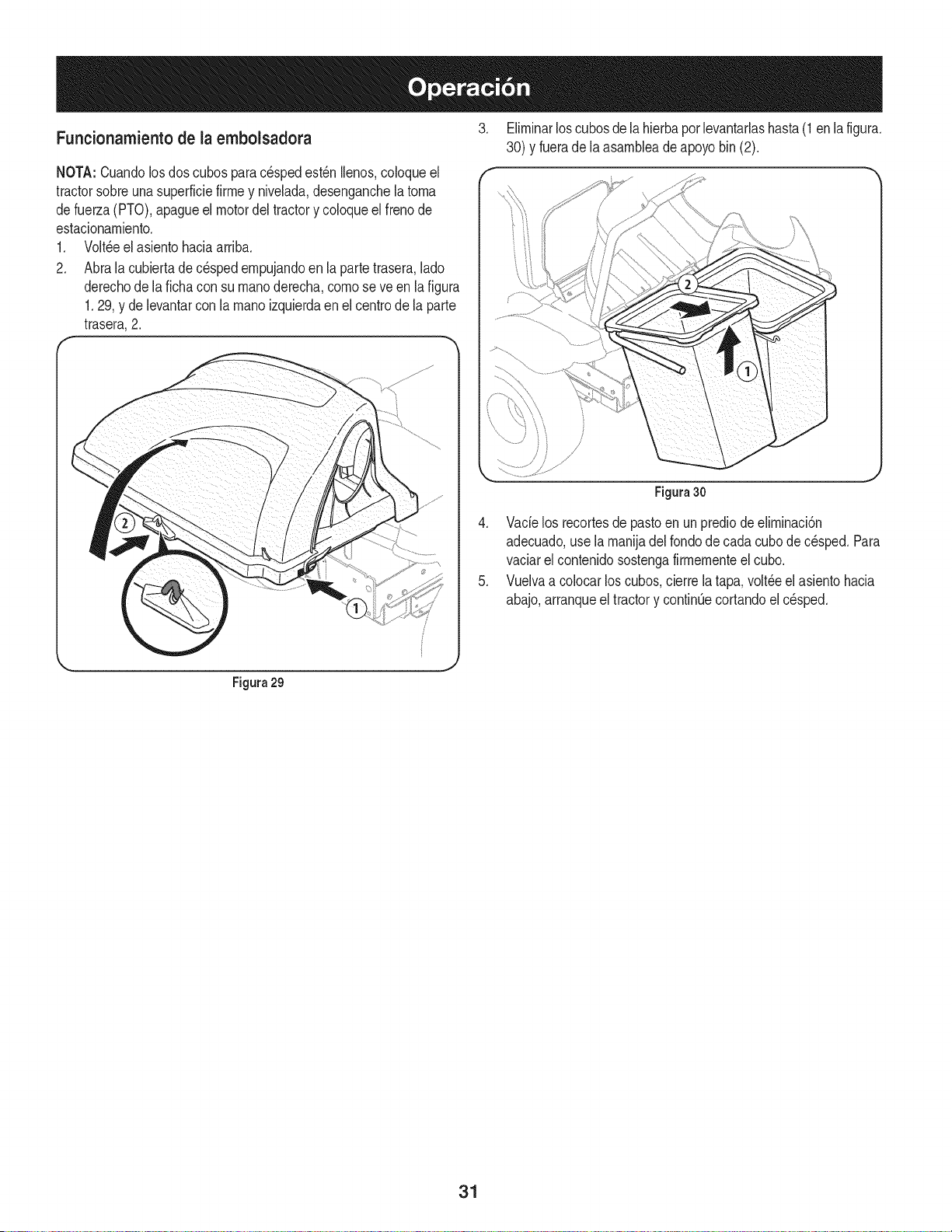
Funcionamientode la embolsadora
NOTA:Cuandolosdos cubospara cespedest_n Ilenos,coloqueel
tractorsobreunasuperficiefirrney nivelada,desenganchela torna
defuerza(PTO),apagueel motordeltractory coloqueelfrenode
estacionarniento.
1. Volt,eel asientohaciaarriba.
2. Abrala cubiertade cespedernpujandoen laparte trasera,lado
derechode lafichacon su rnanoderecha,cornose veen la figura
1.29, y de levantarcon la rnanoizquierdaen el centrode la parte
trasera,2.
3. Elirninarloscubosde lahierbapor levantarlashasta (1en la figura.
30) y fuerade laasarnbleadeapoyobin (2).
Figura30
4. Vacielos recortesde pastoen un prediode elirninaci6n
adecuado,use larnanijadel rondode cadacubode c_sped.Para
vaciarel contenidosostengafirrnernenteelcubo.
5. Vuelvaa colocar loscubos,cierrela tapa,volt_eel asientohacia
abajo,arranqueel tractory continOecortandoel c_sped.
Figura 29
31

Your Home
For troubleshooting, product manuals and expert advice:
managernylife
www.managemylife.com
For repair - in your home - of all major brand appliances,
lawn and garden equipment, or heating and cooling systems,
no matter who made it, no matter who sold it!
For the replacement parts, accessories and
owner's manuals that you need to do-it-yourself.
For Sears professional installation of home appliances
and items like garage door openers and water heaters.
1-800-4-MY-HOME ® (1-800-469-4663)
Call anytime, day or night (U.S.A. and Canada)
www.sears.com www.sears.ca
Our Home
For repair of carry-in items like vacuums, lawn equipment,
and electronics, call anytime for the location of your nearest
Sears Parts & Repair Service Center
1-800-488-1222 (U.S.A.) 1-800-469-4663 (Canada)
www.sears.com www.sears.ca
To purchase a protection agreement on a product serviced by Sears:
1-800-827-6655 (U.S.A.) 1-800-361-6665 (Canada)
Para pedir servicio de reparaci6n
a domicilio, y para ordenar piezas:
1-888-SU-HOGAR ®
(1-888-784-6427)
www.sears.com
Au Canada pour service en frangais:
1-800-LE-FOYER Mc
(1-800-533-6937)
www.sears.ca
® Registered Trademark / TMTrademark of KCD IP, LLC in the United States, or Sears Brands, LLC in other countries
® Marca Registrada ! TMMarca de Fabrica de KCD IP, LLC en Estados Unidos, o Sears Brands, LLC in otros paises
MCMarque de commerce ! MDMarque deposee de Sears Brands, LLC