Operator's Manual
I:RAFrSMAN°
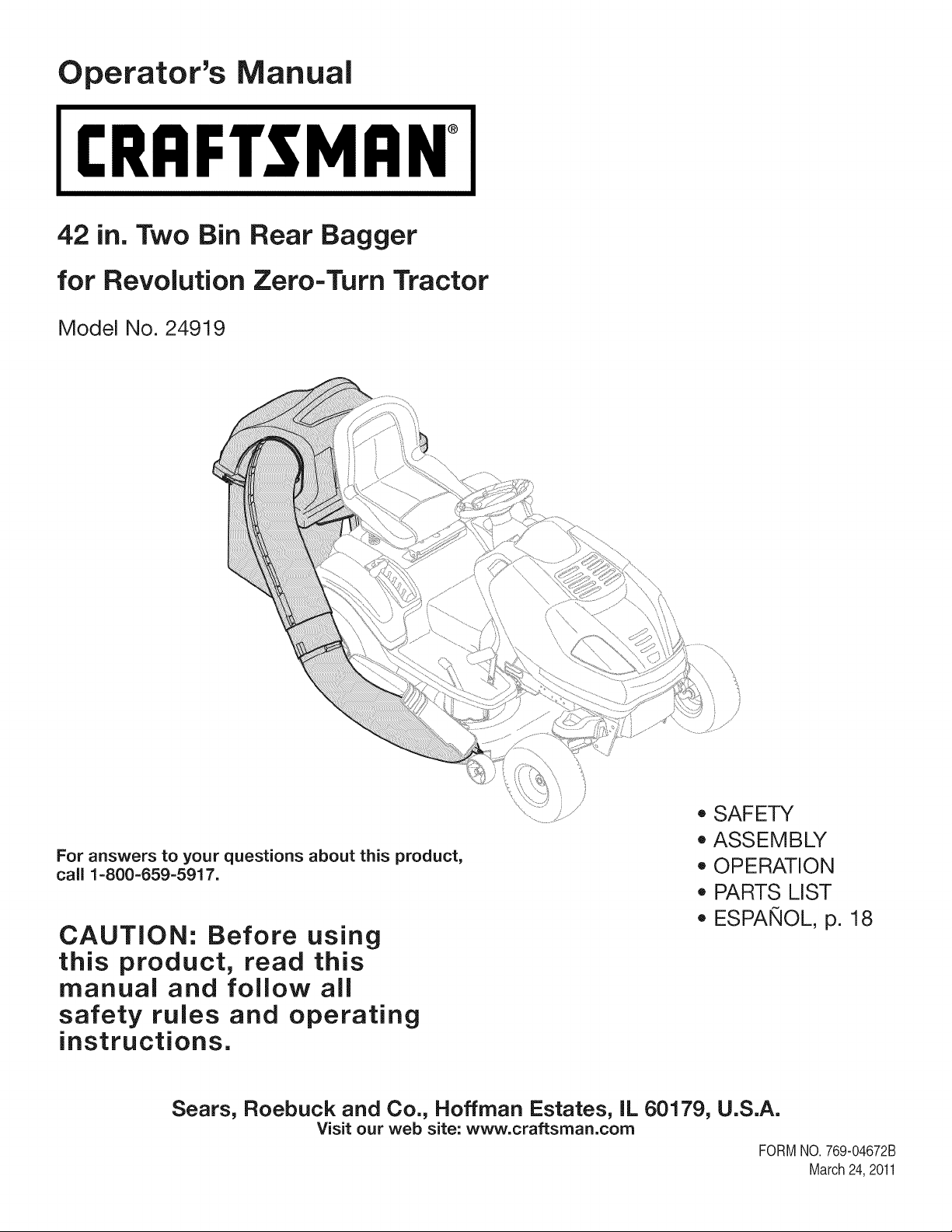
42 in. Two Bin Rear Bagger
for Revolution Zero-Turn Tractor
Model No. 24919
For answers to your questions about this product,
call 1-800-659-5917.
CAUTION: Before using
this product, read this
manual and follow all
safety rules and operating
instructions.
o SAFETY
o ASSEMBLY
o OPERATION
o PARTS LIST
o ESPANOL, p. 18
Sears, Roebuck and Co., Hoffman Estates, IL 60179, U.S.A.
Visit our web site: www.craftsman.com
FORM1/0. 769-04672B
March24,2011

SafeOperationPractices..............................................3-4
SlopeGuide.......................................................................5
Contentsof Carton& HardwarePacks..........................6-7
AssemblyandInstallation............................................8-14
Operation........................................................................15
PartsList....................................................................16-17
Espa_ol............................................................................18
ServiceNumbers.............................................BackCover
Craftsman Full Warranty
Ifthis Craftsmanproductfails due to a defectin materialor workmanshipwithinoneyearfromthe dateof purchase,returnit to any Searsstoreor
otherCraftsmanoutlet in the UnitedStatesfor free replacement.
ThiswarrantycoversONLYdefectsin materialandworkmanship.Searswill NOTpayfor:
• Replacementof bags,which are expendableitemsthatcan wearoutfrom normalusewithin thewarrantyperiod.
• Repairsnecessarybecauseof accidentorfailureto operateor maintainthe productaccordingto all suppliedinstructions.
Thiswarrantyappliesforonly 90 days if this productis everusedfor commercialor rentalpurposes.
Thiswarrantyappliesonly whilethis productis usedin the UnitedStates.
Thiswarrantygivesyou specificlegal rights,and you mayalso haveotherrightswhich vary from stateto state.
Sears, Roebuck and Co., Hoffman Estates, IL 60179
© SearsBrands,LLC 2
Thissymbolpointsout importantsafetyinstructionswhich,if not
followed,couldendangerthepersonalsafetyand/orpropertyof
yourselfandothers. Readand followall instructionsin thismanual
beforeattemptingto operatethis machine.Failureto complywith
theseinstructionsmay resultin personalinjury.Whenyou seethis
symbol,HEEDITSWARNING!
CALIFORNIA PROPOSITION 65
EngineExhaust,someof itsconstituents,and certainvehicle
componentscontainoremitchemicalsknownto Stateof California
to cause cancerand birthdefects or other reproductiveharm.
Batteryposts,terminals,and relatedaccessoriescontainlead and
leadcompounds,chemicalsknownto the Stateof Californiato
causecancerandreproductiveharm.Washhandsafter handling.
Thisattachmentwas builtto be usedaccordingto the safeopera-
tion practicesin this manual.Carelessnessor error on the part of
the operatorcan resultin seriousinjury.Mowersarecapableof
amputatinghandsandfeetandthrowingobjects.Failureto observe
the followingsafetyinstructionsas wellas the instructionsprovided
withyour mower,could resultin seriousinjuryor death.
Your Responsibility--Restrictthe use of this powermachineto
personswho read,understandand follow thewarningsand instruc-
tionsin thismanualandon the machine.
SAVE THESE INSTRUCTIONS!
GENERAL OPERATION
,, Read,understand,and followall instructionson your equipmentand
intheir manualsbeforeattemptingto assembleand operate.Keepthis
manualina safe placefor futureand regularreferenceandfor ordering
replacementparts.
,, Tohelp avoidbladecontact or a thrown objectinjury,keepbystanders,
helpers,childrenand petsat least 75 feetfromthe mowerwhile it is in
operation.Stop machineif anyoneentersthe area.
,, Thoroughlyinspectthe areawherethe equipmentis to be used.Remove
all stones,sticks, wire, bones, toys,and other foreignobjectswhich
couldbe pickedup and thrownby the blade(s).Thrownobjects can
causeseriouspersonalinjury.
,, Alwayswearsafetyglasses or safetygogglesduringoperationand while
performinganadjustmentor repairto protectyoureyes.Thrownobjects
whichricochet can causeseriousinjuryto the eyes.
,, Do not operatethe mowerwithoutthe dischargecoveror entire grass
catcherinits properplace.A missingor damageddischargecoveror
grass bagattachmentcomponentmayresult inthrown objectsor blade
contactinjuries.
,, Do not put hands orfeet near rotatingparts or underthe cutting deck.
Contactwiththe blade(s) can amputatehandsand feet.
,, Shut off mower'sengineand waitfor bladesto come to a completestop
beforeuncloggingmower'sdischargeopeningor baggerparts.
,, Slow downbeforeturning. Operatethe machinesmoothly.Avoiderratic
operationandexcessivespeed.Be awarethata grasscatcherattach-
mentcan affectthe handlingcharacteristicsof your mower.
,, Disengageblade(s), set parkingbrake,stop engineand waituntil the
blade(s)cometo a completestop beforeopeningbaggerattachment's
top cover,removinggrass catcher,emptyinggrass,uncloggingchute,
removingany grass ordebris, or makingany adjustments.
,, Neverleave a runningmachineunattended.Alwaysturn offblade(s),
placetransmissionin neutral,set parkingbrake,stopengine andremove
keybeforedismounting.
,, Your machineis designedto cut normalresidentialgrassof a heightno
morethan 10".Do not attemptto mowthrough unusuallytall, dry grass
(e.g.,pasture)or pilesof dry leaves.Drygrass or leaves maycontact
the engineexhaustand/or build up on the mowerdeck presentinga
potentialfirehazard.
,, If situationsoccur whichare not coveredinthis manual,usecare and
good judgment.Contact 1-800-659-5917for assistance.
3
SLOPE OPERATION
Slopesare a majorfactor relatedto loss of control andtip-overaccidents
whichcan resultinsevere injury or death. Attachmentscan also affect the
stabilityof the machine.All slopesrequireextra caution.
For yoursafety,use the slope guideincludedas partof this manualto
estimatetheangle of slopesbeforeoperatingthis machineon a slopedor hilly
area.If theslope is greaterthan 10degreesas shown on the slopeguide,do
notoperatethe mowerwith the grass bagattachmentinstalledonthat area or
seriousinjury could result.
DO:
1. Mow up anddown slopes,not across.Exerciseextremecautionwhen
changingdirectionon slopes.
2. Watchfor holes,ruts,bumps,rocks,or other hiddenobjects. Uneven
terraincouldoverturnthe machine.Tall grasscan hideobstacles.
3. Useslow speed. Choosea low enoughspeedsetting sothat you will not
haveto stop or shift whileon the slope.Tires maylosetractionon slopes
eventhoughthe brakesarefunctioningproperly.Alwayskeepmachine
in gear when goingdown slopesto takeadvantageof engine braking
action.
4. Followthe manufacturer'srecommendationsfor wheelweightsor
counterweightsto improvestability. For recommendations,contact
1-800-659-5917.
5. Keepall movementonthe slopesslow and gradual.Do notmakesud-
denchangesin speedor direction.Rapidengagementor brakingcould
causethe front of the machineto lift and rapidlyflip overbackwards
whichcouldcauseserious injury.
6. Avoidstartingor stoppingon a slope.If tires losetraction,disengagethe
blade(s) andproceedslowly straightdownthe slope.
DO NOT:
1. Do not turn on slopes unlessnecessary;then, turn slowlyand gradually
downhill,if possible.
2. Do not mow near drop-offs,ditchesor embankments.The mowercould
suddenlyturn over if a wheel is overthe edgeof a cliff, ditch, or if an
edge caves in.
3. Do not try to stabilizethe machineby putting yourfooton theground.
4. Do not use a grasscatcheron steepslopes.
5. Do not mow on wet grass. Reducedtractioncould causesliding.
GENERAL SERVICE
1. Beforecleaning,repairing,or inspecting,makecertainthe blade(s)
and all movingparts havestopped. Disconnectthe spark plugwireand
ground againsttheengine to preventunintendedstarting.
2. Keep all nuts, bolts,and screwstightto be surethe equipmentis in safe
workingcondition.
3. Nevertamperwith yourmower'ssafetyinterlocksystemor other safety
devices.Checktheir proper operationregularly.
4. Neverattemptto makeadjustmentsor repairswhile the mower'sengine
is running.
5. Grasscatchercomponentsandthe dischargecoverare subjectto wear
and damagewhichcould expose movingpartsor allowobjectsto be
thrown.For safetyprotection,frequentlycheck componentsand replace
immediatelywith originalequipmentmanufacturer's(O.E.M.)parts only,
listed inthis manual.Useof parts whichdo not meetthe originalequip-
ment specificationsmay leadto improperperformanceandcompromise
safety!
6. Maintainor replacesafetyand instructionlabels, as necessary.
SAFETY SYMBOLS
This section depicts and describes safety symbols that may appear on this product. Read, understand, and follow all instructions on the machine
before attempting to assemble and operate.
I
I
READTHEOPERATOR'SMANUAL(S)
Read,understand,andfollow all instructionsinthe manual(s)beforeattemptingto assembleand
operate
STOP
Turnoffthe engine beforeopeningthe baggercover.
4
05
(1)
o
_c
=o
09
g
o
E
g-
c
O
o
E
o
(:1)
o
cb
.m
(:1)
.9o
13)
.-z2
E_
¢d
(D
E)b
¢d
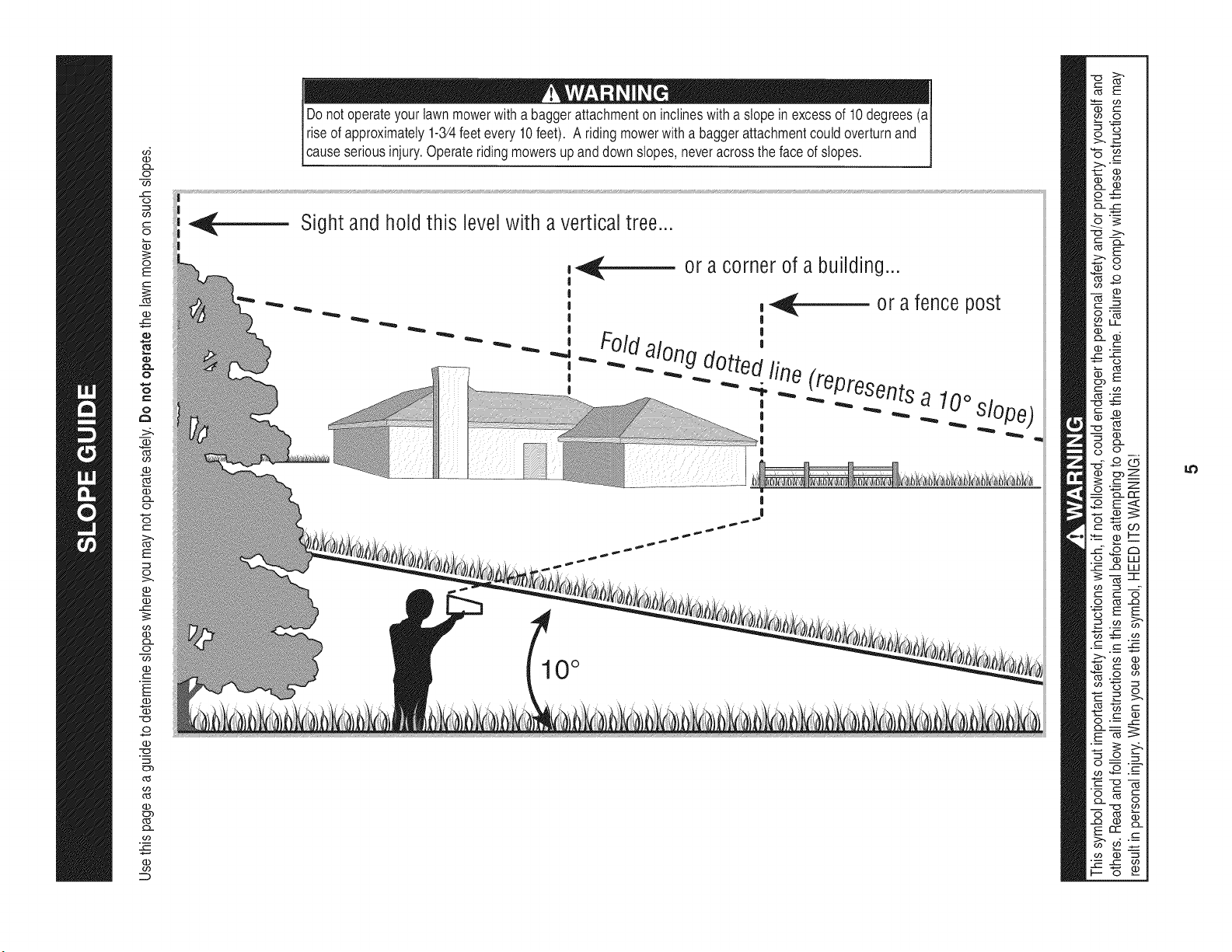
Do notoperateyour lawnmowerwitha baggerattachmenton inclineswith a slopein excessof 10 degrees(aI
I riseof approximately1-3/4feet every 10feet). A riding mowerwith a baggerattachmentcouldoverturnand
[cause seriousinjury.Operater dng mowersup and downs opes,neveracrossthe face of s opes.
Sight and hold this level with a vertical tree..,
or a corner of a building...
_- or a fence post
|
Foldalong d_ "
u_ed fin _epresents
_ _ e
, _ a 10° slo
10 °
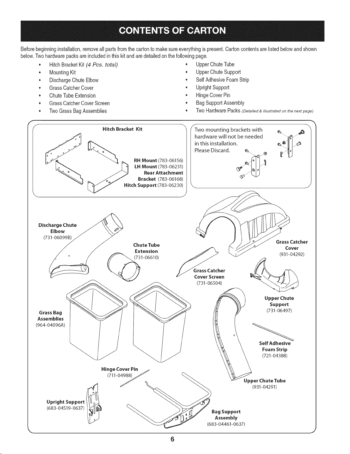
Beforebeginninginstallation,removeallparts from the cartonto makesureeverythingis present.Cartoncontentsarelisted belowand shown
below.Twohardwarepacksare includedin this kit and are detailedon thefollowingpage.
• Hitch BracketKit (4 Pcs. total)
• MountingKit
• DischargeChuteElbow
• GrassCatcherCover
• ChuteTubeExtension
GrassCatcherCoverScreen
TwoGrassBagAssemblies
• UpperChuteTube
• UpperChute Support
• SelfAdhesiveFoamStrip
• UprightSupport
• HingeCover Pin
• Bag SupportAssembly
TwoHardwarePacks(Detailed & illustrated on the next page)
S
Hitch Bracket Kit
__ RH Mount (783-06156)
" .[_ ,HMount/783-o6231/
_ Rear Attachment
_-_ j._%_ Bracket (783-06168)
Hitch Support (783-06230)
J
Two mounting brackets with e_ _j_
hardware will not be needed "fall
in this installation, e_¢_Illf_
Please Discard. e_. _'Iv
Discharge Chute
Elbow
(731-06099B)
Grass Bag
Assemblies
(964-04096A)
Upright Support
(683-04519-0637)
Chute Tube
Extension
1-0661 O)
Grass Catcher
Cover Screen
(731-06504)
Grass Catcher
Cover
(931-04292)
)__ Upper Chute
Support
(731-06497)
Self Adhesive
FoamStrip
(721-04388)
HingeCover Pin ._
(711-04988)_ _\
J _. _ UpperChute Tube
I_u'T" "_. J_#f,_I./ BagSupport
ttY ">-."--__._ [J7 Assembly
"_" __ (683-04461-0637)
6
_J
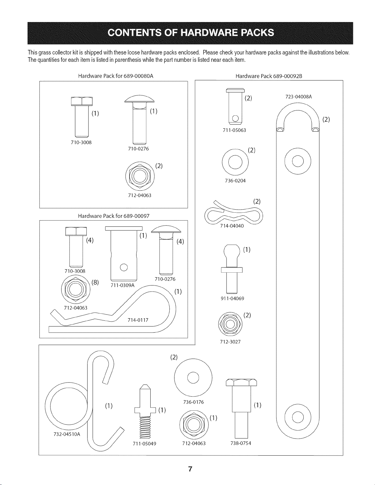
Thisgrasscollectorkitis shippedwith theseloosehardwarepacksenclosed. Pleasecheckyour hardwarepacksagainstthe illustrationsbelow.
Thequantitiesfor eachitem is listedin parenthesiswhilethe part numberis listedneareachitem.
Hardware Pack for 689-00080A
1) (1)
710-3008
710-0276
(2)
712-04063
Hardware Pack for 689-00097
[_(4)
710-3008
(8)
712-04063
0
711-0309A
I
(I)
](4)
710-0276
1)
714-0117
732-04510A
711-05049
736-0176
(1)
712-04063
Hardware Pack 689-00092B
_(2) 723-04008
711-05063
2)
736-0204
(2)
714-04040
(I)
911-04069
(2)
712-3027
) ]_ (1)
738-0754
(2)
7
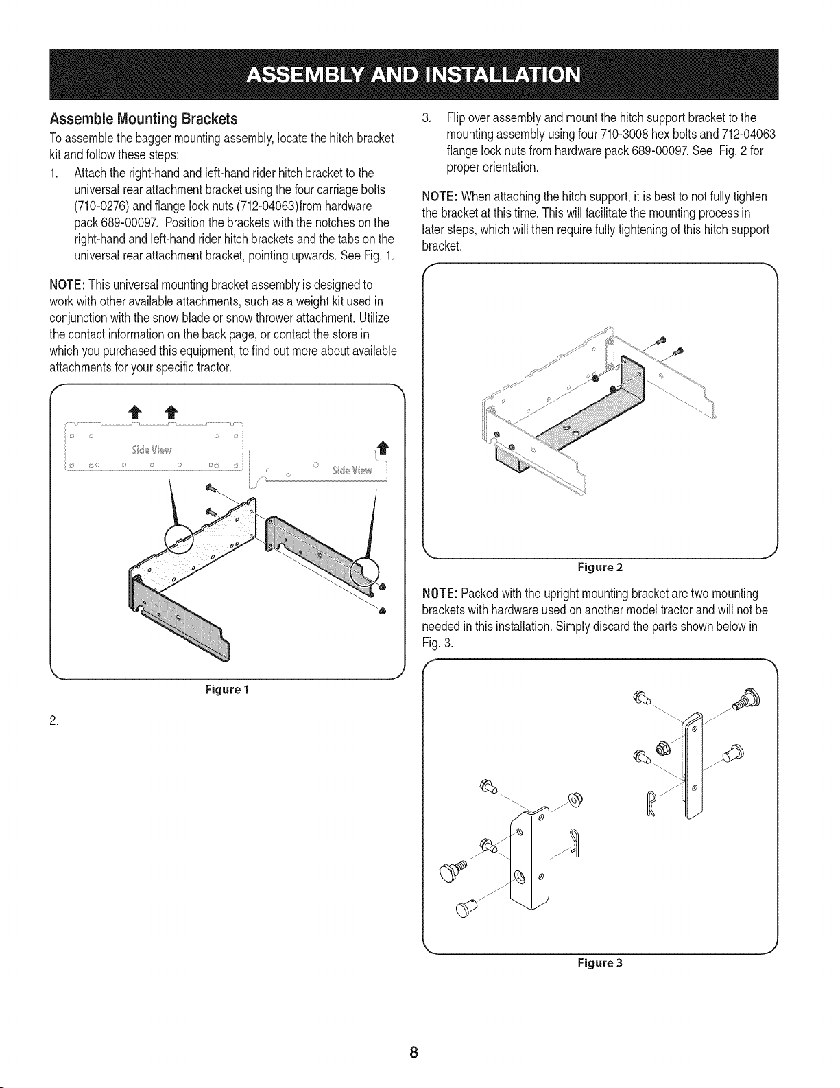
Assemble Mounting Brackets
Toassemblethe baggermountingassembly,locatethe hitch bracket
kitandfollowthesesteps:
1. Attachthe right-handand left-handrider hitchbracketto the
universalrearattachmentbracketusingthe four carriagebolts
(710-0276)andflange locknuts(712-04063)fromhardware
pack689-00097. Positionthe bracketswith the notchesonthe
right-handand left-handrider hitch bracketsand the tabson the
universalrearattachmentbracket,pointingupwards.SeeFig. 1.
.
Flipoverassemblyandmountthe hitch supportbracketto the
mountingassemblyusingfour 710-3008hex boltsand 712-04063
flangelocknutsfromhardwarepack689-00097.See Fig.2 for
properorientation.
NOTE: Whenattachingthehitch support,it is best to notfully tighten
the bracketat thistime. Thiswillfacilitatethe mountingprocessin
later steps,whichwill then requirefully tighteningof this hitch support
bracket.
NOTE:Thisuniversalmountingbracketassemblyis designedto
workwithotheravailableattachments,such as a weightkitused in
conjunctionwith the snowbladeor snowthrowerattachment.Utilize
thecontactinformationon the backpage,or contactthe storein
whichyou purchasedthis equipment,to find out moreaboutavailable
attachmentsfor your specifictractor.
Figure 2
NOTE:Packedwiththe uprightmountingbracketaretwo mounting
bracketswithhardwareusedon anothermodeltractorand will notbe
neededin thisinstallation.Simplydiscardthe partsshownbelowin
Fig.3.
.
Figure 1
Figure 3
8

Assembling The Bin Support Assembly
Locatethe uprightsupport bracketand the binsupportassembly.
Assembleit by followingthesesteps:
1. Laythe bin supportassemblytopsidedownwith the mounting
bracketportionfacingupwards.
2. Insertthe notchedendof the verticalsupportbracketintothe bin
supportassembly,as in Fig.4, and securewith a carriagebolt
(710-0276)andflangelock nut (712-04063)packedin withthe
uprightsupportbracket.See Fig.5.
Figure 4
Figure 6
Installthe clevispin (711-0309A)from hardwarepack689-00097
intothe tractor'shitchand the assembly'shitch supportand
securewitha hairpinclip (710117)in the top hole(closestto the
headof the pin). See Fig. 7.
ignholeonbracket
withholeontractor
/
/
Figure 7
Figure 5
Mount Assembly on Tractor
Installthe mountingassemblyon the tractoras follows:
1. Slidethebaggermountingassemblyalongthe top of the frame
rails,as in Fig.6, until theassemblyhooksunder the shoulder
boltsonthe tractor.At this pointthe hitch supportholeon the
mountingassemblyandthe holeon thetractor'shitchplatewill
lineup.
NOTE:Theclevispincan be feddownthroughthehitch supportand
securedunderneathwith the hairpinclip,as seenin Fig.7,or it may be
easierto feedthe clevispin upthroughthe hitch platehole and secure
withthe hairpinclip onthe topside.The latter methodmaybe preferred
sinceit can be easierto insertthe hairpinclip. Eitherwaywill work;the
decisionshouldbebasedon operatorpreference.
3. Tightenall of the hardwaresecuringthe hitchsupportat this time.
9
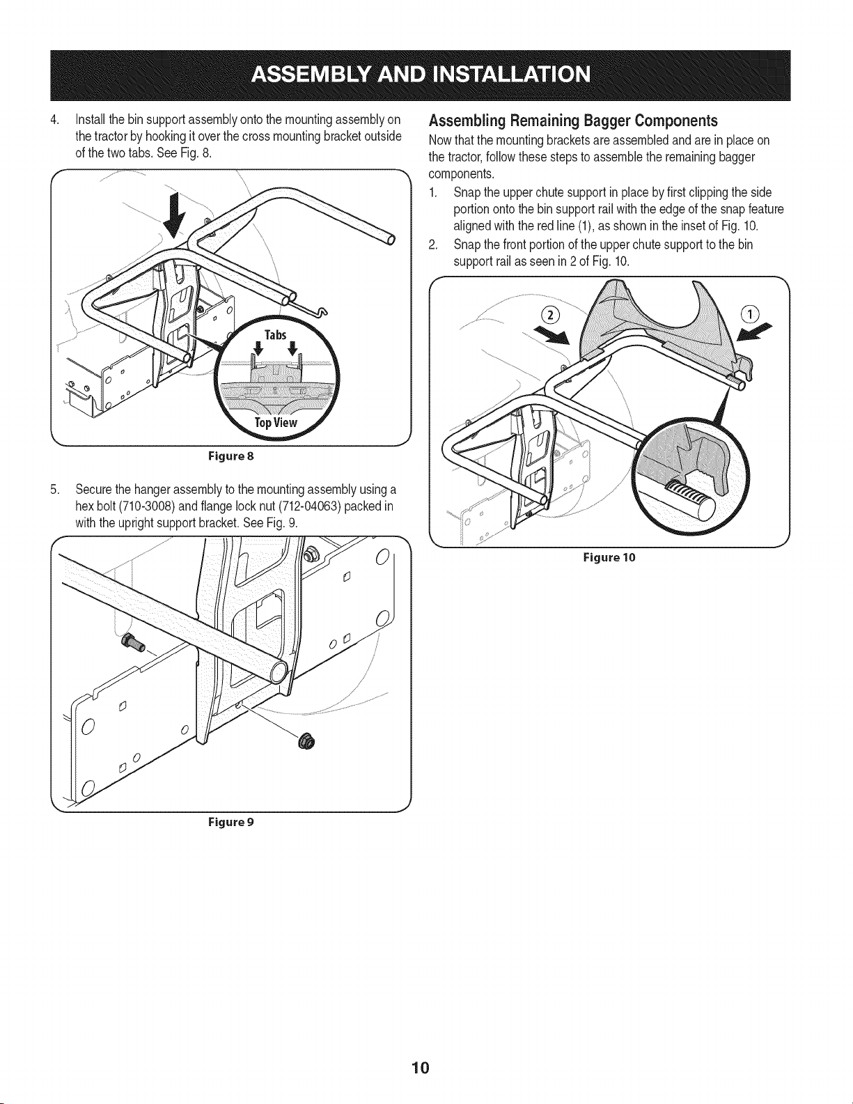
4. Installthe binsupportassemblyonto themountingassemblyon
thetractorby hookingit overthe crossmountingbracketoutside
of the twotabs.See Fig.8.
Figure8
Assembling Remaining Bagger Components
Nowthatthe mountingbracketsareassembledandarein placeon
the tractor,follow these stepsto assemblethe remainingbagger
components.
1. Snapthe upperchute supportin placebyfirst clippingthe side
portiononto thebin supportrail with the edgeof the snapfeature
alignedwiththe redline (1),as showninthe insetof Fig. 10.
2. Snap the frontportionof the upper chutesupportto the bin
supportrail as seenin 2 of Fig. 10.
.
Securethe hangerassemblyto the mountingassemblyusinga
hexbolt (710-3008)and flangelock nut (712-04063)packedin
withthe uprightsupport bracket.See Fig. 9.
Figure 10
Figure 9
10

3. Installthegrass catchercover screenintothe baggercoverby
first insertingthe endclosestto the sidewith thecutoutinto the
mountinghole,as in Fig. 11.Makesureto feedthe screenunder
the lip,as in Fig. 12.
f
Figure 13
.
Figure 11
Clipin the otherside byflexing thescreenand pushingit down
intothe providedcutouthole.See Fig. 12.
Make sure screen sits
t
under the cover s lip
Figure12
.
.
Installthegrasscatchercoveronto the binsupportassembly,as
seenin Fig.13.Thegrasscatchercovergoes insideof the two
mountingtabson the bin supportassembly.
Slidethehingepininto the holelocatedon the mountingtab, as
in Fig.14. Usethecut-outwindow(Seeinsetin Fig.14)to line up
the hingepin on the othersideandpush pinallthe way in untilit
reachesthe end-stop.At thispointthe pinclips intoplaceandis
securedbya tab in the baggercover.SeeFig. 15.
Figure 14
Figure 15
J
11
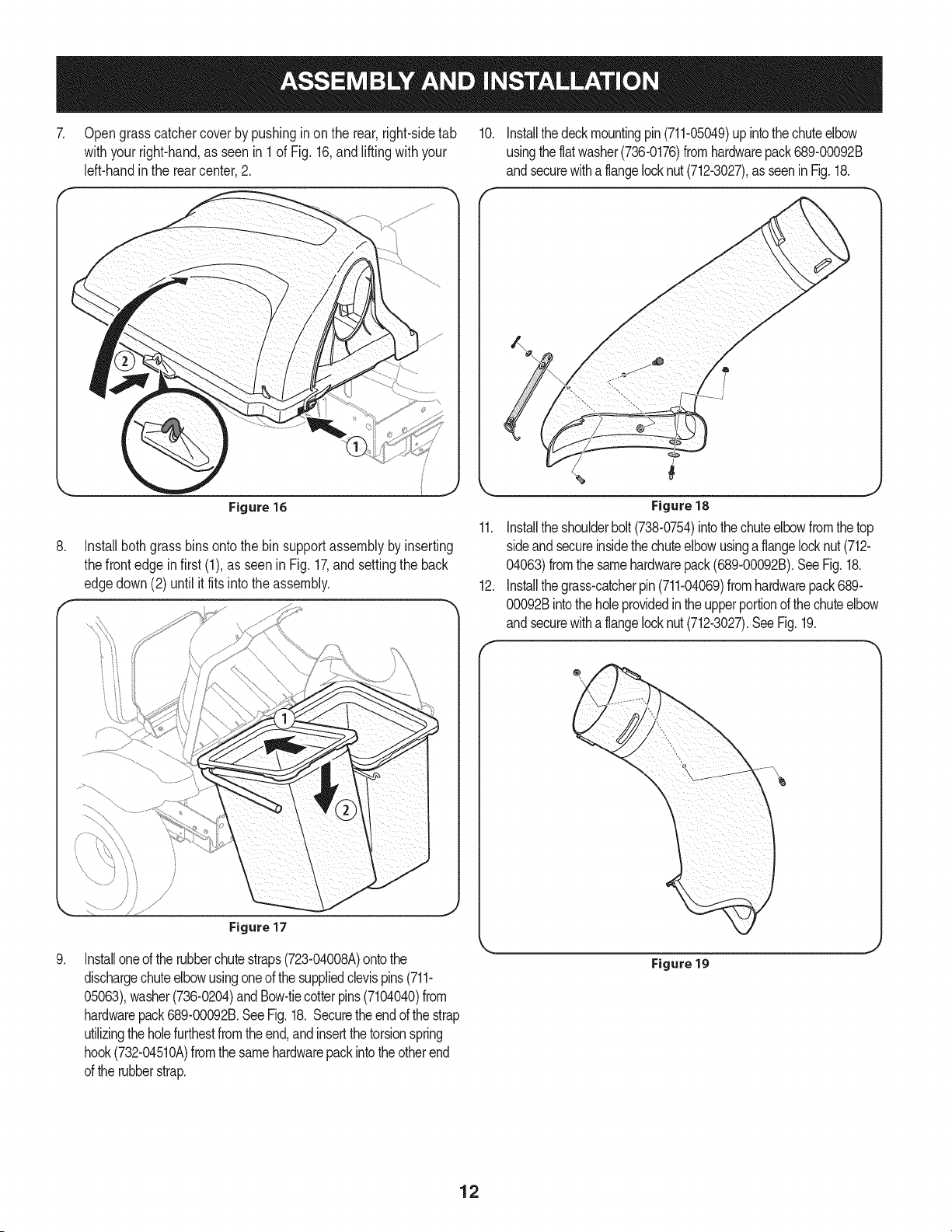
7. Opengrass catchercover by pushinginon the rear,right-sidetab 10. Installthedeckmountingpin(711-05049)upintothechuteelbow
withyourright-hand,as seenin 1 of Fig. 16,and lifting with your usingtheflatwasher(736-0176)fromhardwarepack689-00092B
left-handinthe rearcenter,2. andsecurewitha flangelocknut(712-3027),as seenin Fig.18.
f
J
.
.
Figure 16
Installbothgrassbinsontothe bin supportassemblyby inserting
thefrontedgein first (1),as seenin Fig.17,andsettingthe back
edgedown (2) until it fits into theassembly.
Figure 17
Installoneof therubberchutestraps(723-04008A)ontothe
dischargechuteelbowusingoneof thesuppliedclevispins(711-
05063),washer(736-0204)and Bow-tiecotterpins(7104040)from
hardwarepack689-00092B.SeeFig.18. Securetheendof thestrap
utilizingtheholefurthestfromtheend,andinsertthetorsionspring
hook(732-04510A)fromthesamehardwarepackintotheotherend
ofthe rubberstrap.
11.
12.
Figure18
Installtheshoulderbolt(738-0754)intothechuteelbowfromthetop
sideandsecureinsidethechuteelbowusinga flangelocknut(712-
04063)fromthe samehardwarepack(689-00092B).SeeFig.18.
Installthegrass-catcherpin(711-04069)fromhardwarepack689-
00092Bintothe holeprovidedin theupperportionof thechuteelbow
andsecurewitha flangelocknut(712-3027).SeeFig.19.
®
Figure 19
12

13. Installrubberstrap(723-04008A)ontothechutetubeextensionusing 14.
clevispin (711-05063),flatwasher(736-0204)and bow-tiecotterpin
(7104040)fromhardwarepack689-00092B.Attachtheend with
theholeclosestto theendofthe strap,asseenin Fig.20.Thiswill
makeit easierto grabontothestrapto pull,stretchandhookonto
thegrass-catcherpinpreviouslyinstalledonthechuteelbowinthe f
previousstep.
Figure20
Withthe tractor'sdischargechuteraisedup and heldopen, install
the chute elbowoverthe chuteopeningby placingthe deck
mountingpinin the holeprovided,as seenin Fig.21,then secure
the elbowto the deck by hookingthe retainerstrap torsionspring
hookoverthe deck wheelmountingbracketa seenin Fig.22.
Figure 21
Figure 22
13
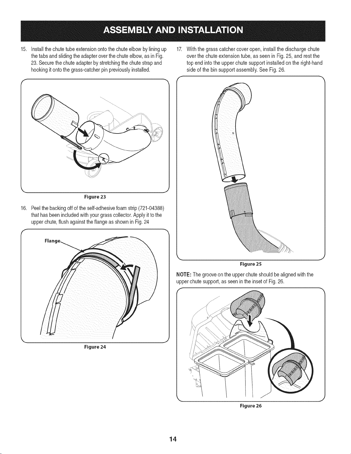
15. Installthechutetubeextensionontothe chuteelbow bylining up 17.
thetabsand slidingthe adapteroverthe chuteelbow,as in Fig.
23. Securethe chuteadapterby stretchingthe chutestrapand
hookingit onto the grass-catcherpin previouslyinstalled.
Withthe grasscatchercoveropen, install the dischargechute
over the chuteextensiontube, as seen in Fig. 25, and restthe
top end into the upper chute support installed on the right-hand
side of the bin supportassembly.See Fig. 26.
16.
Figure 23
Peelthe backingoff of the self-adhesivefoam strip (721-04388)
thathas beenincludedwithyourgrasscollector.Applyit tothe
upperchute,flushagainstthe flangeas shownin Fig. 24
/
Figure24
Figure 25
NOTE: Thegrooveon the upperchuteshouldbe alignedwith the
upperchute support,as seenin the insetof Fig.26.
Figure 26
14
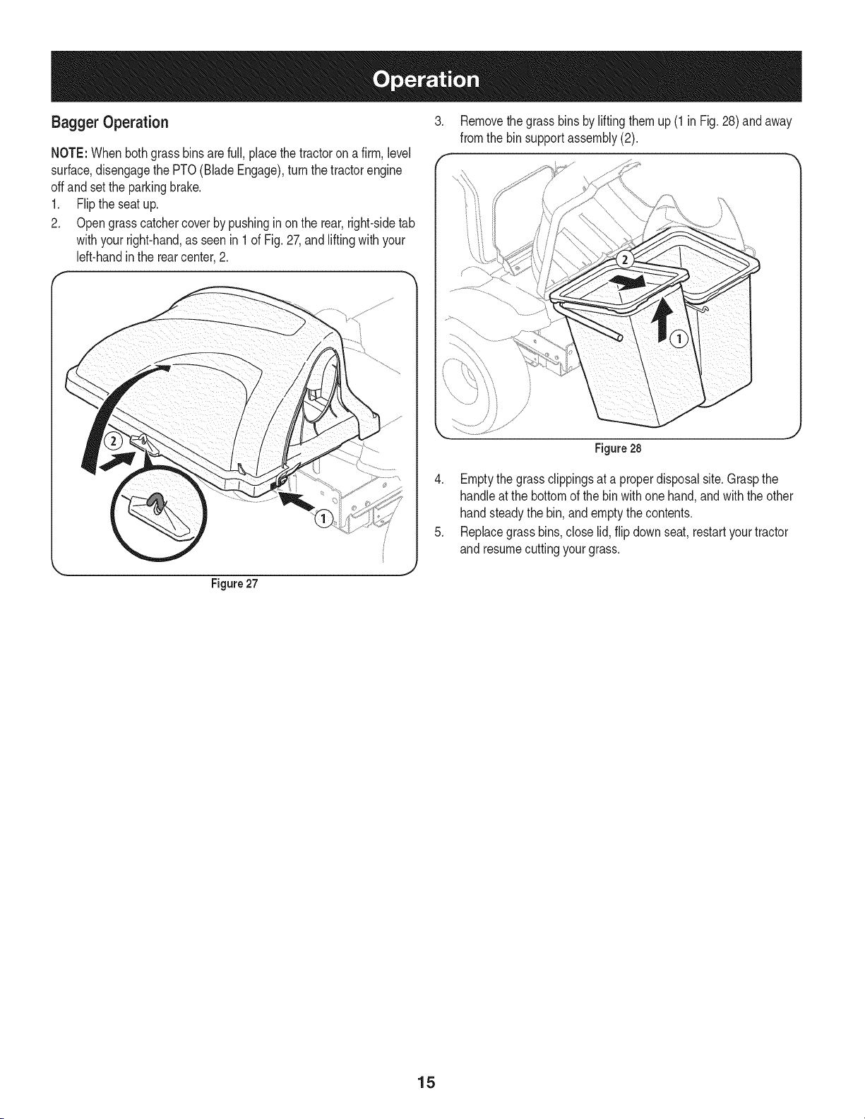
Bagger Operation 3.
f
NOTE:Whenbothgrassbinsare full,placethetractoron afirm, level
surface,disengagethe PTO(Blade Engage),turn the tractorengine
offand setthe parkingbrake.
1. Flipthe seatup.
2. Opengrass catchercover by pushinginon the rear,right-sidetab
withyourright-hand,as seenin 1 of Fig. 27,and liftingwith your
left-handinthe rearcenter,2.
Removethe grassbinsby liftingthem up (1 in Fig. 28) and away
fromthe bin supportassembly(2).
J
Figure27
Figure28
4. Emptythe grassclippingsat a properdisposalsite.Graspthe
handleat the bottomof the bin with one hand,and with the other
handsteadythe bin, and emptythecontents.
5. Replacegrass bins,close lid, flip downseat,restartyourtractor
and resumecuttingyourgrass.
15
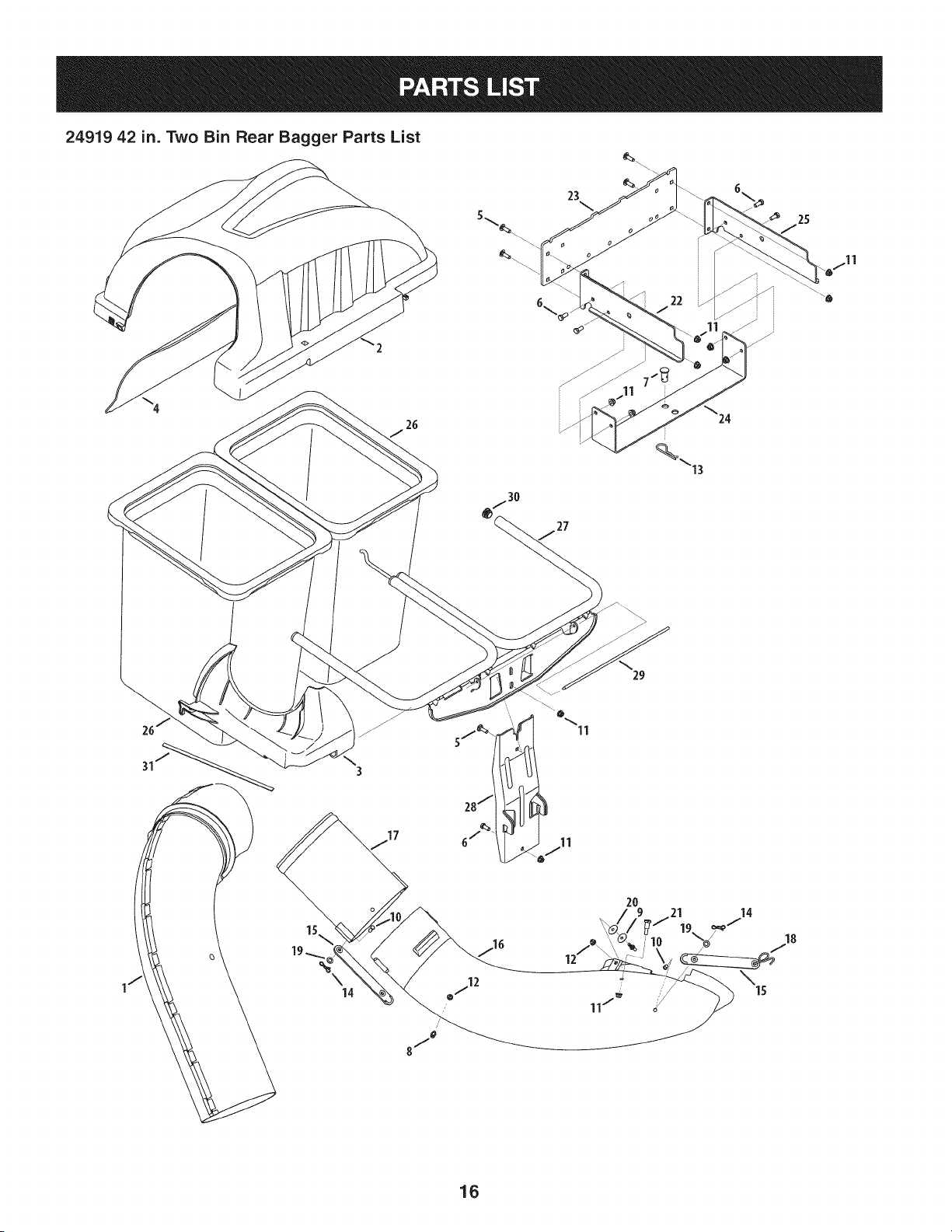
24919 42 in. Two Bin Rear Bagger Parts List
23
26
27
29
2O
18
J
16

24919 42 in. Two Bin Rear Bagger Parts List
I
Ref. I Part Number
I. 931-04291
2. 931-04292
3. 731-06497
4. 731-06504
5. 710-0276
6. 710-3008
7. 711-0309A
8. 911-04069
9. 711-05049
10. 711-05063
11. 712-04063
12. 712-3027
13. 714-0117
14. 714-04040
15. 723-04008A
16. 731-06099B
17. 731-06610
18. 732-04510A
19. 736-0204
20. 736-0176
21. 738-0754
22. 783-06156-0637
23. 783-06168-0637
24. 783-06230-0637
25. 783-06231-0637
26. 964-04096A
27. 683-04461
28. 683-04519
29. 711-04988
30. 735-0246A
31. 721-04388
Description
Upper Chute Assembly
Double Bagger Cover Assembly
Upper Chute Support
Bagger Cover Screen
Carriage Screw, 5/16-18 x 1.00"
Hex Head Screw, 5/16-18 x .75"
Clevis Pin, .62" Dia.
Grass-catcher Pin, 1/4-20
Attachment Pin, 1/4 x 0.66 Lg.
Clevis Pin, 5/16 x .75 Lg.
Flange Lock Nut, 5/16-18
Flange Lock Nut, 1/4-20
Internal Cotter Pin, .148 x 3.00
Bow-Tie Cotter Pin, 72
Chute Strap, 6.00 Lg.
Bagger Discharge Chute, Elbow
Bagger Chute Adapter, 7 In.
Torsion Spring Hook
Flat Washer, .344 x .62 x .033
Flat Washer, .265 x .938 x .120
Shoulder Screw, .437 x .54
Mounting Bracket, RH
Universal Mounting Bracket
Universal Bracket Support, I-Series
Mounting Bracket, LH
Grass Bin (2 total)
Double Bag Support Assembly
Vertical Support Bracket
Cover Hinge Pin
End Plug
Self-Adhesive Foam Strip
17

Craftsman Total Garantia
CraftsmanSieste productofalla debidoa undefectode materialo manode obradentrode unaSoa partirde la fechadecompra,el retornoa
cualquierfiendaSearso cualquierotra Craftsmande salidaenlos EstadosUnidospara la sustituci6ngratuita.
EstagaranfiacubreQnicamentedefectosde materialy manode obra. Searsnopagar&por:
• Sustituci6ndelas bolsas,quesonfungiblesquepuedenIlevara cabo a partir dela utilizaci6nnormalen elperiodode
garanfia.
• Las reparacionesnecesariasa causade accidenteo el fracasoparaoperaro mantenerel productode acuerdocon todaslas
instruccionessuministradas.
Estagarantiaseaplicaa s61o90 dias si este productoes utilizadocadavez con finescomercialeso alquiler.
Estagaranfias61ose aplicamientraseste productose utilizaen los EstadosUnidos.
Estagaranfiale otorgaderechoslegalesespecificos,y ustedtambi_npuedetenerotrosderechosque variande un estadoa otro.
Sears, Roebuck and Co., Hoffman Estates, IL 60179
© SearsBrands,LLC 18
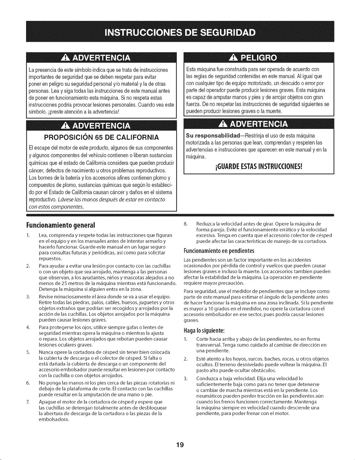
Lapresenciadeeste sirnboloindicaque setrata de instrucciones
irnportantesde seguridadquese deben respetarpara evitar
poneren peligrosu seguridadpersonaly/o materialy lade otras
personas.Leay siga todaslas instruccionesde este manualantes
de poneren funcionarnientoesta rn_quina.Si no respetaestas
instruccionespodria provocarlesionespersonales.Cuandoveaeste
sirnbolo,ipresteatenci6na la advertencia!
PROPOSICION 65 DE CALIFORNIA
Elescapedel motordeeste producto,algunosde suscornponentes
y algunoscornponentesdelvehiculocontieneno liberan sustancias
quirnicasqueel estado de Californiaconsideraque puedenproducir
c_ncer,defectosde nacirnientouotros problernasreproductivos.
Losbornesdela bateriay los accesoriosafinescontienenplornoy
cornpuestosde plorno,sustanciasquirnicasque segOnIo estableci-
do pot el Estadode Californiacausanc_ncery da_osen el sisterna
reproductivo.Ldveselas manos despu_sde estar en contacto
con estoscomponentes.
Estarn&quinarueconstruidaparaseroperadade acuerdocon
las reglasde seguridadcontenidasenestemanual.AI igualque
concualquiertipo de equipo rnotorizado,un descuidoo error por
partedeloperadorpuedeproducirlesionesgraves.Estarn&quina
es capazde arnputarrnanosy piesy dearrojarobjetoscon gran
fuerza.Deno respetarlas instruccionesde seguridadsiguientesse
puedenproducirlesionesgraveso larnuerte.
Su responsabilidad--Restrinja el usode estarn_quina
rnotorizadaa las personasque lean,cornprendany respetenlas
advertenciase instruccionesqueaparecenen estemanualy en la
rn_quina.
iGUARDEESTASINSTRUCCIONES!
Fundonamiento general
1. Lea, comprenda y respete todas las instrucciones que figuran
en el equipo yen los manuales antes de intentar armarlo y
hacerlo funcionar. Guarde este manual en un lugar seguro
para consultas futuras y peri6dicas, asi como para solicitar
repuestos.
2. Para ayudar a evitar una lesidn pot contacto con las cuchillas
o con un objeto que sea arrojado, mantenga alas personas
que observan, a los ayudantes, ni_os y mascotas alejados a no
menos de 25 metros de la m_quina mientras est_ funcionando.
Detenga la m_quina si alguien entra en la zona.
3. Revise minuciosamente el _irea donde se va a usar el equipo.
Retire todas las piedras, palos, cables, huesos, juguetes y otros
objetos extrahos que podrian ser recogidos y arrojados por la
accidn de las cuchillas. Los objetos arrojados por la m_quina
pueden causar lesiones graves.
4. Para protegerse los ojos, utilice siempre galas o lentes de
seguridad mientras opera la m&quina o mientras la ajusta
o repara. Los objetos arrojados que rebotan pueden causar
lesiones oculares graves.
5. Nunca opere la cortadora de c_sped sin tenet bien colocada
la cubierta de descarga o el colector de c_sped. Si falta o
est_ da_ada la cubierta de descarga oun componente del
accesorio embolsador puede resultar en lesiones por contacto
con la cuchilla o con objetos arrojados.
6. No ponga las manos ni los pies cerca de las piezas rotatorias ni
debajo de la plataforma de corte. El contacto con las cuchillas
puede resultar en la amputacidn de una mano o pie.
7. Apague el motor de la cortadora de c_sped y espere que
las cuchillas se detengan totalmente antes de desbloquear
la abertura de descarga de la cortadora o las piezas de la
embolsadora.
8. Reduzca la velocidad antes de girar. Opere la m_quina de
forma pareja. Evite el funcionamiento err_tico y la velocidad
excesiva. Tenga en cuenta que el accesorio colector de c6sped
puede afectar las caracteristicas de manejo de su cortadora.
Fundonamiento en pendientes
Las pendientes son un factor importante en los accidentes
ocasionados por p_rdida de control y vuelcos que pueden causar
lesiones graves e incluso la muerte. Los accesorios tambien pueden
afectar la estabilidad de la m_iquina. La operaci6n en pendiente
requiere mayor precaucidn.
Para seguridad, use el medidor de pendientes que se incluye como
parte de este manual para estimar el _ingulo de la pendiente antes
de hacer funcionar la m_iquina en una zona inclinada. Si la pendiente
es mayor a 10 grados en el medidor, no opere la cortadora con el
accesorio embolsador en ese sector, pues podria causar lesiones
graves.
I-lagaIo siguiente:
1. Corte hacia arriba y abajo de las pendientes, no en forma
transversal. Tenga sumo cuidado al cambiar de direcci6n en
una pendiente.
2. Est_ atento a los hoyos, surcos, baches, rocas, u otros objetos
ocultos. El terreno desnivelado puede voltear la m_quina. El
pasto alto puede ocultar obst_iculos.
3. Conduzca a baja velocidad. Elija una velocidad Io
suficientemente baja como para no tenet que detenerse
o cambiar de marcha mientras est,1 en la pendiente. Los
neum&ticos pueden perder tracci6n en las pendientes aun
cuando los frenos funcionen correctamente. Mantenga
la m_quina siempre en velocidad cuando desciende una
pendiente, para poder frenar con el motor.
19
4. Siga las recomendaciones del fabricante sobre pesos y
contrapesos de las ruedas, para mejorar la estabilidad.
5. Haga que todos los movimientos en las pendientes sean
lentos y graduales. No cambie repentinamente la velocidad
ni la direcci6n. Un frenado o cambio de velocidad repentinos
pueden causar que el frente de la m_iquina se levante y d_ una
voltereta hacia atr_is, Io que podria causar lesiones graves.
6. Evite arrancar o detenerse en una pendiente. Si los neum_iticos
pierden traccidn, desenganche las cuchillas y descienda
lentamente la pendiente.
No haga Iosiguiente:
I. No gire en una pendiente a menos que sea imprescindible. De
ser posible, gire lenta y gradualmente cuesta abajo.
2. No corte el c_sped cerca de barrancos, zanjas o terraplenes. La
cortadora de c_sped podria volcarse repentinamente si una de
las ruedas estuviera sobre el borde de un acantilado o zanja, o
si un borde se desmoronara.
3. No intente estabilizar la m_iquina poniendo el pie en el suelo.
4. No utilice un colector de c_sped en pendientes empinadas.
5. No corte el c_sped humedo. Una reducci6n en tracci6n puede
causar derrapes.
Sewido general
I. Antes de limpiar, reparar o inspeccionar la m_quina,
compruebe que las cuchillas y todas las piezas m6viles se
hayan detenido. Desconecte el cable de la bujia y p6ngalo
haciendo masa contra el motor para evitar que arranque
accidentalmente.
2. Mantenga todas las tuercas, pernos y tornillos bien ajustados
para asegurarse de que el equipo est,1 en condiciones seguras
de operaci6n.
3. Nunca intente violar el sistema de bloqueo de seguridad u
otros mecanismos de seguridad de la cortadora. Controle
peri6dicamente que funcionan correctamente.
4. No intente nunca hacer ajustes o reparaciones a la cortadora
mientras el motor est,1 en marcha.
5. Los componentes del colector de c_sped y la cubierta de
descarga est_fin sujetos a desgaste y dahos que podrian dejar
expuestas piezas que se mueven o permitir que se arrojen
objetos. Para proteger su seguridad, verifique frecuentemente
todos los componentes y reempl_icelos inmediatamente
unicamente con piezas de los fabricantes del equipo original
(O.E.M.) indicados en este manual. El uso de piezas que no
cumplen con las especificaciones del equipo original puede
resultar en rendimiento inadecuado y puede poner en peligro
la seguridad.
6. Mantenga o reemplace las etiquetas de seguridad y de
instrucciones segun sea necesario.
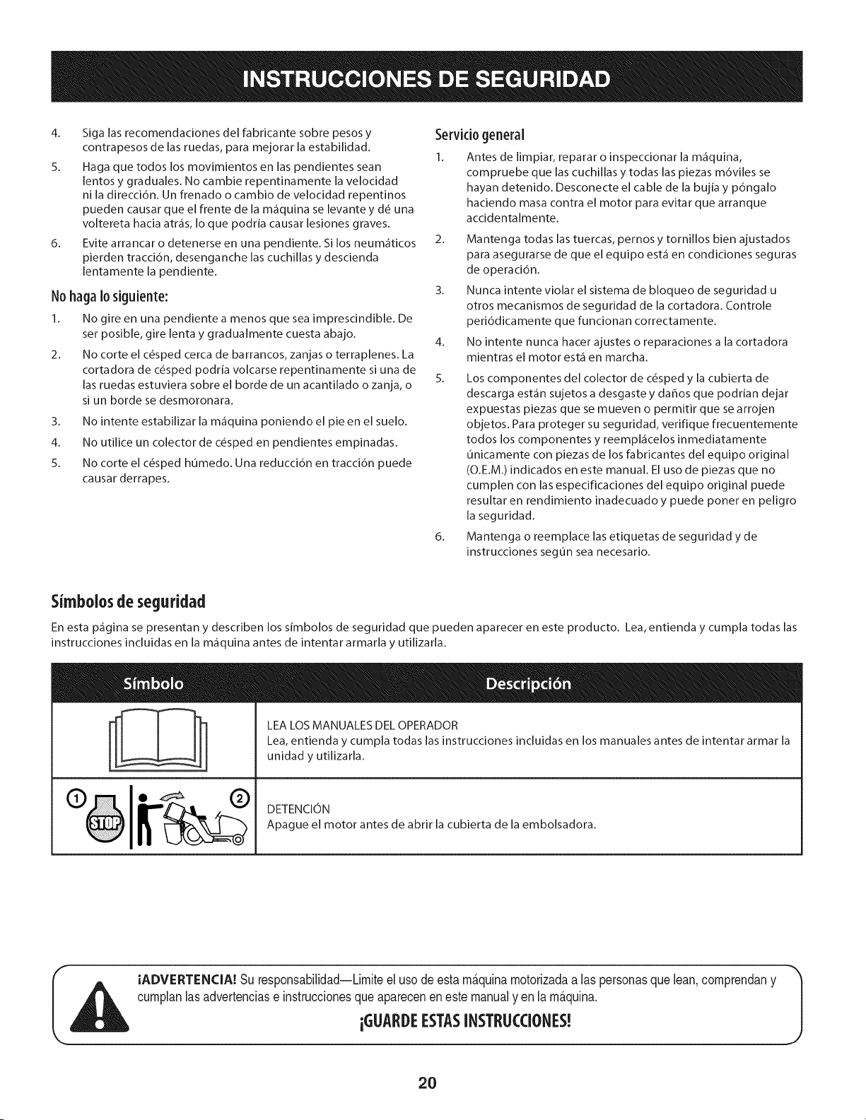
Simbolosde seguridad
En esta p_gina se presentan y describen los simbolos de seguridad que pueden aparecer en este producto. Lea, entienda y cumpla todas las
instrucciones incluidas en la m_quina antes de intentar armarla y utilizarla.
LEA LOS MANUALES DEL OPERADOR
Lea, entienda y cumpla todas las instrucciones incluidas en los manuales antes de intentar armar la
unidad y utilizarla.
DETENCION
Apague el motor antes de abrir la cubierta de la embolsadora.
IADVERTENCIA! Su responsabilidad--Limiteel usode esta m&quinamotorizadaalas personasque lean,comprendany
cumplanlasadvertenciase instruccionesqueapareceneneste manualyen la m&quina.
iGUAI DEESTASINSTRLICCIONES!
2O
"O
(:D
"(1)
CD
e5
O
e5
O
O
E
o
o ,.5
e5 CD
.___-_
Ob_
,e5 ¢O
_g
CD
.o_
_g
I
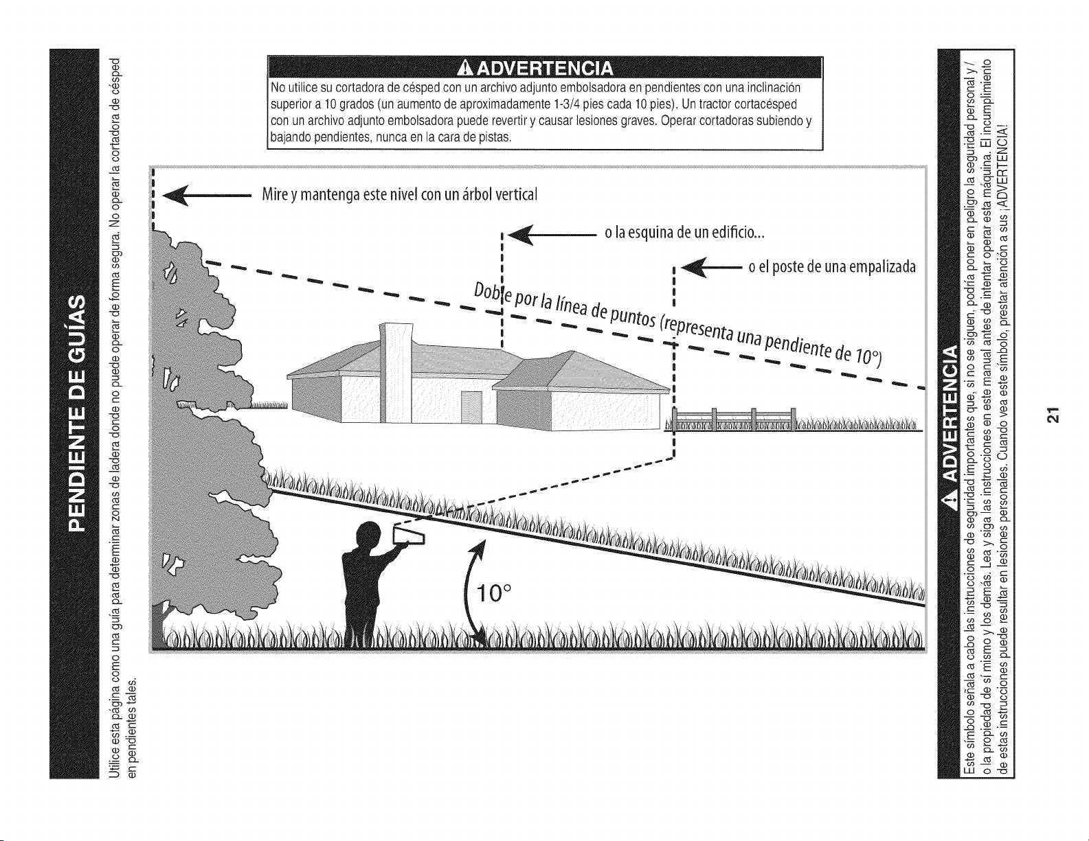
No utilicesu cortadorade cespedcon un archivoadjuntoembolsadoraen pendientescon una inclinacion
superiora 10grados(un aumentode aproximadamente1-3/4piescada 10pies).Untractorcortacesped
conunarchivoadjuntoembolsadorapuederevertiry causarlesionesgraves.Operarcortadorassubiendoy
baandopendentes,nuncaen a carade pstas.
Mirey mantengaeste nivel conun _rbol vertical
, _ o la esquinade un edificio...
I
|
, __ 0 el p0stede una empalizada
I |
bl '
Do epot la lineade
_" "_ -.. PUntos(top
," _ "" ._... ._ ._ _.,resenta._una_pendientede
-- _. .. 700)
I
|
|
|
10°
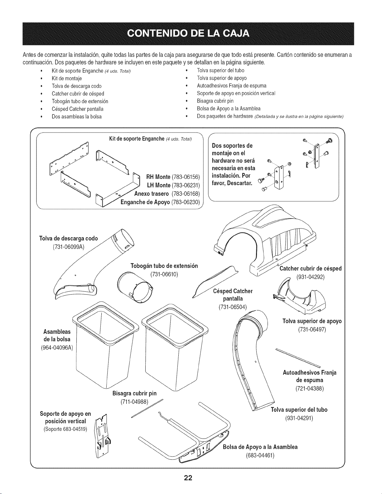
Antesde comenzarla instalaci6n,quitetodas las partesde lacaja paraasegurarsede que todoest,. presente,Cart6ncontenidose enumerana
continuaci6n,Dospaquetesde hardwarese incluyenenestepaquetey se detallanen lap_.ginasiguiente,
• Kit de soporte Enganche(4 uds. Total)
• Kit de montaje
• Tolvade descargacodo
• Catchercubrir de cesped
• TobogAntubo de extensi6n
• CespedCatcherpantalla
• Dosasambleasla bolsa
• Tolvasuperiordeltubo
• Tolvasuperiordeapoyo
• AutoadhesivosFranjadeespuma
• Soportedeapoyoenposici6nvertical
• Bisagracubrirpin
• Bolsade ApoyoalaAsamblea
• Dos paquetesde hardware(Detallada y se flustra en la pagina siguiente)
Kit de soporte Enganche (4uds.Total)
RH Monte(783-06156)
LH Monte (783-06231)
Anexo trasero (783-06168)
Enganchede Apoyo(783-06230_
Dossoportesde
montaje on el
hardware no ser_
necesada en esta
instalaci6n.Pot
favor, Descartar.
Tolva de descarga codo
(731-060_ _Tobog_n tubo de extensidn
@731-06610)
C_sped Catcher
pantalla
(731-06504)
Catchercubrir de c_sped
(931-04292)
Asambleas
de la bolsa
(964-04096A)
Soporte de apoyo en
posici6n vertical
(Soporte683-04519)
Tolvasuperiorde apoyo
(731-06497)
AutoadhesivosFranja
de espuma
Bisagra cubrirpin (721-04388)
(711-_
Tolvasuperior del tubo
(931-04291)
sa deApoyo a la Asamblea
(683-04461)
J
22
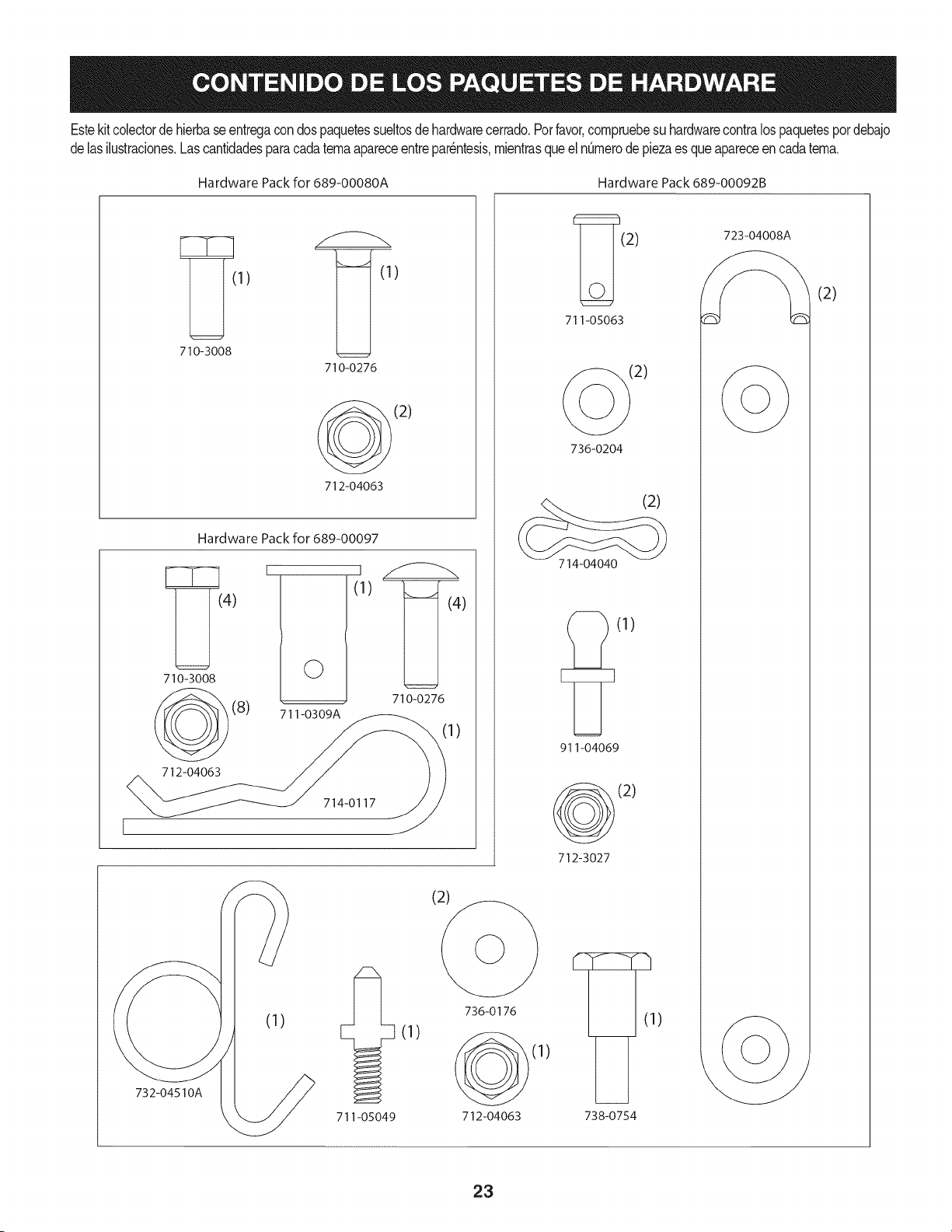
Estekitcolectorde hierbaseentregacondospaquetessueltosdehardwarecerrado.Porfavor,compruebesuhardwarecontralospaquetespordebajo
delasilustraciones.Lascantidadesparacadatemaapareceentrepar_ntesis,mientrasqueel n0merodepiezaes queapareceencadatema.
Hardware Packfor 689-00080A Hardware Pack689-00092B
1) )
710-3008
710-0276
(2)
712-04063
Hardware Pack for 689-00097
{4)
710-3008
712-04063
(8)
I
©
711-0309A
I
(1)
[I (4)
710-0276
1)
714-0117
732-04510A
711-05049
(2)
(1)
736-0176
712-04063
_9(2 ) 723-04008
711-05063
t2)
736-0204
(2)
714-04040
(1)
911-04069
(2)
712-3027
)
(1)
738-0754
(2)
23
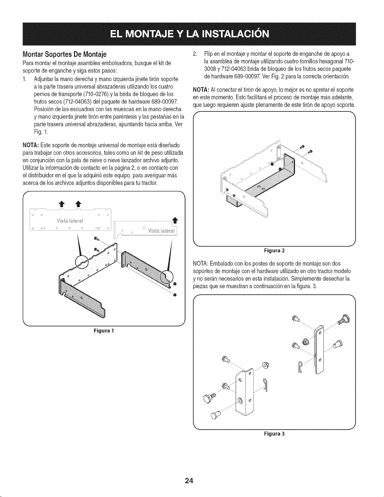
MontarSoportes De IVlontaje
Paramontarel montajeasambbaembolsadora,busqueel kitde
soportedeenganchey sigaestospasos:
1. Adjuntarla manoderechay manoizquierdajinetetir6n soporte
a la partetraserauniversalabrazaderasutilizandoloscuatro
pernosde transporte(710-0276)y la bridade bloqueode los
frutossecos(712-04063)del paquetede hardware689-00097.
Posici6nde las escuadrascon las muescasen lamanoderecha
y manoizquierdajinete tir6nentrepar_ntesisy las pestaSasen la
partetraserauniversalabrazaderas,apuntandohaciaarriba.Vet
Fig. 1.
NOTA: Estesoportede montajeuniversalde montajeest,.diseSado
paratrabajarconotrosaccesorios,tales cornoun kit de peso utilizada
enconjunci6ncon la pala de nieveo nievelanzadorarchivoadjunto.
Utilizarla informaci6nde contactoen la p_.gina2, o en contactocon
eldistribuidoren el quela adquiri6esteequipo,para averiguarm_.s
acercade losarchivosadjuntosdisponiblesparatu tractor.
t t
Figura 1
,
Flipenel montajey montarel soportede enganchede apoyoa
la asambleade montajeutilizandocuatrotornilloshexagonal710-
3008y 712-04063brida de bloqueode losfrutos secospaquete
de hardware689-00097.Vet Fig. 2 para la correctaorientaci6n.
NOTA: AIconectarel tir6nde apoyo,Iornejores noapretarel soporte
en estemomento.Estofacilitar_,el procesodemontajem_.sadelante,
que luegorequierenajustepbnamentede este tir6nde apoyosoporte.
Figura 2
NOTA:Embaladocon lospostesdesoportede rnontajesondos
soportesdemontajeconel hardwareutilizadoen otrotractormodelo
y noser_.nnecesariosen esta instalaci6n.Simpbmentedesecharla
piezasque se muestrana continuaci6nen la figura.3.
Figura 3
,J
24
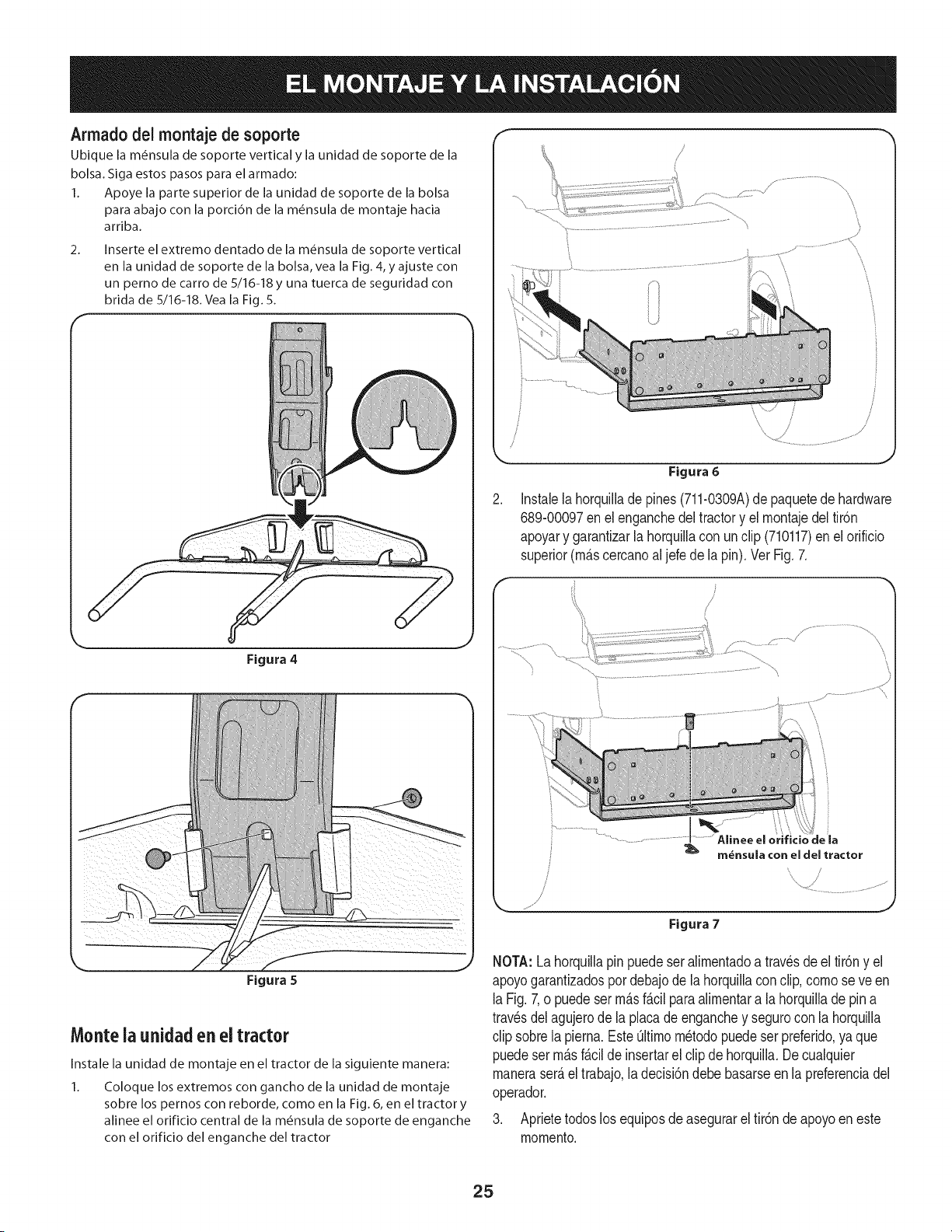
Armado del montaje de soporte
Ubique la m_nsula de soporte vertical y la unidad de soporte de la
bolsa. Siga estos pasos para el armado:
1. Apoye la parte superior de la unidad de soporte de la bolsa
para abajo con la porci6n de la m_nsula de montaje hacia
arriba.
Inserte el extremo dentado de la m_nsula de soporte vertical
en la unidad de soporte de la bolsa, vea la Fig. 4, y ajuste con
un perno de carro de 5/16-18 y una tuerca de seguridad con
brida de5/16-18.Veala Fig.5.
Figura 4
2_
\
/
/
Figura 6
Instalela horquillade pines(711-0309A)depaquetede hardware
689-00097enel enganchedel tractory el rnontajedeltir6n
apoyary garantizarla horquillacon un clip (710117)enel orificio
superior(m_.scercanoaljefe de la pin). Vet Fig. 7.
\
\
Figura 7
Figura 5
Monte ia unidaden el tractor
Instale la unidad de montaje en el tractor de la siguiente manera:
1. Coloque los extremos con gancho de la unidad de montaje
sobre los pernos con reborde, como en la Fig. 6, en el tractor y
alinee el orificio central de la m_nsula de soporte de enganche
con el orificio del enganche del tractor
NOTA:Lahorquillapinpuedeser alimentadoa travesde el tir6ny el
apoyogarantizadospor debajode la horquillaconclip, como se veen
laFig.7,o puedeserm_.sf_.cilparaalirnentara la horquillade pina
trav_sdelagujerode laplacade enganchey segurocon la horquilla
clip sobrela pierna.EsteOltimom_todopuede serpreferido,ya que
puedeserm_.sf_.cilde insertarelclip de horquilla.Decualquier
maneraser_.eltrabajo,la decisi6ndebe basarseen la preferenciadel
operador.
3. Aprietetodoslos equiposde asegurareltir6n deapoyoeneste
momento.
25
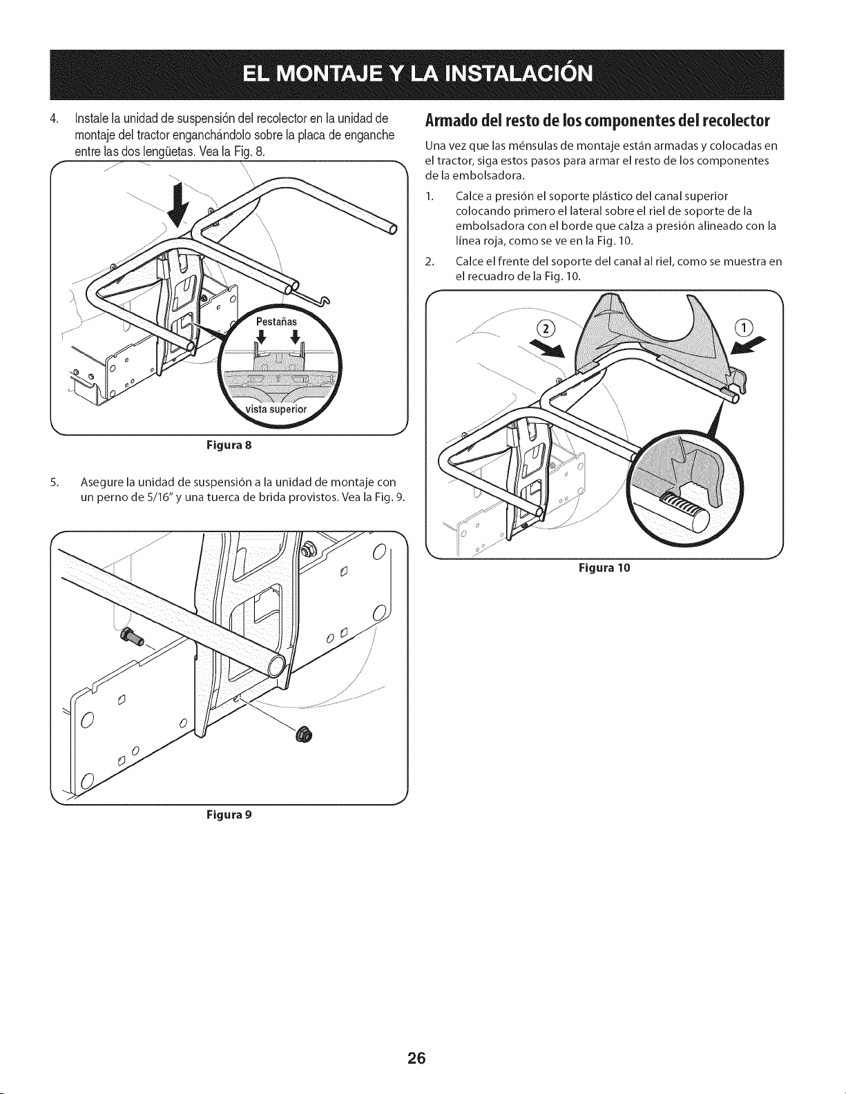
,
Instalelaunidadde suspensi6ndel recolectoren launidadde
montaje del tractor enganchfindolo sobre la placa de enganche
entrelas dosleng0etas.Yeala Fig. 8.
Armado dei resto de los ¢omponentes del recolector
Una vez que las m6nsulas de montaje est_fin armadas y colocadas en
el tractor, siga estos pasos para armar el resto de los componentes
de la embolsadora.
1. Calce a presi6n el soporte pl_istico del canal superior
colocando primero el lateral sobre el riel de soporte de la
embolsadora con el borde que calza a presi6n alineado con la
linea roja, como se ve en la Fig. 10.
2. Calce el frente del soporte del canal al riel, como se muestra en
el recuadro de la Fig. 10.
Figura 8
Asegure la unidad de suspensi6n a la unidad de montaje con
un perno de 5/16" y una tuerca de brida provistos. Vea la Fig. 9.
Figura 10
Figura 9
26
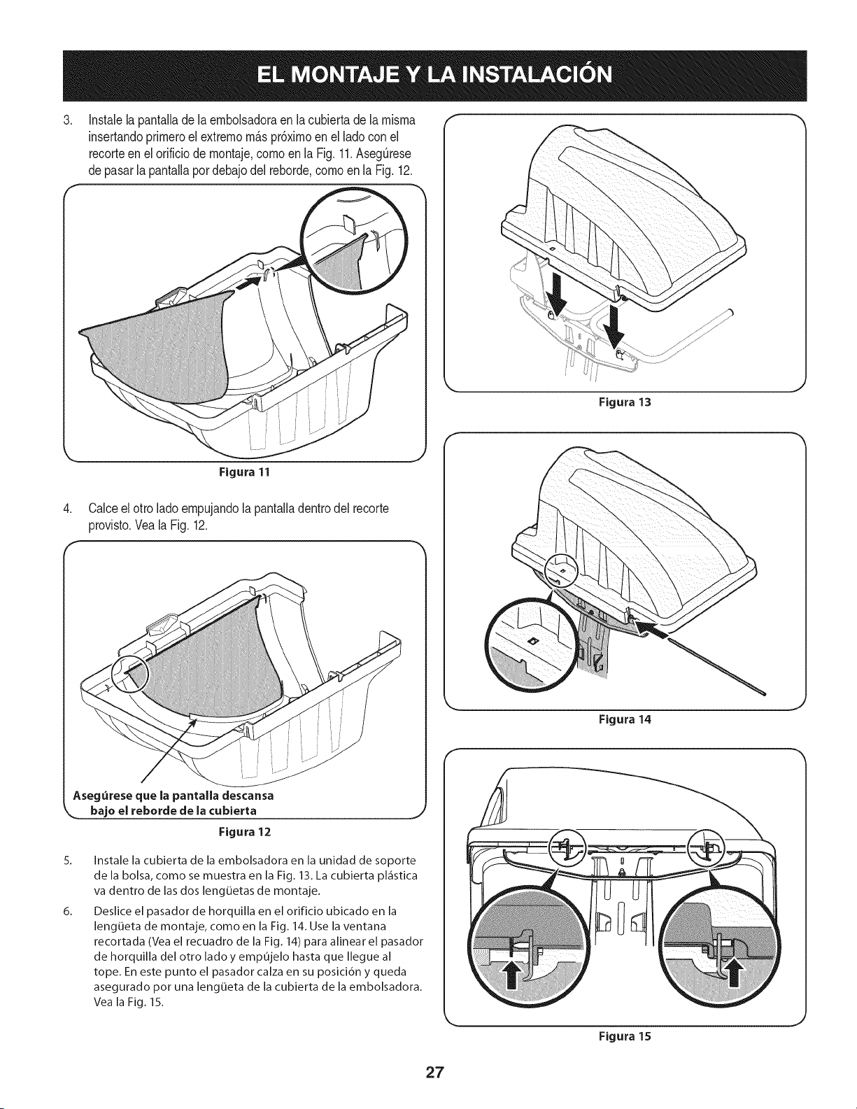
,
Instalelapantallade la embolsadoraen la cubiertade lamisma
insertandoprimeroel extrernom_spr6ximoen el lado conel
recorteenel orificiodemontaje,comoen la Fig.11.AsegQrese
depasarla pantallapordebajodel reborde comoen la Fig. 12.
Figura 13
,
Figura 11
Calceel otto ladoempujandolapantalladentrodel recorte
provisto.Veala Fig. 12.
Aseg_rese que la pantalla descansa
,.= bajo el reborde de |a cubierta _,
Figura 12
5_
6_
Instale la cubierta de la embolsadora en la unidad de soporte
de la bolsa, como se muestra en la Fig. 13. La cubierta pl_fistica
va dentro de las dos lengQetas de montaje.
Deslice el pasador de horquilla en el orificio ubicado en la
lengQeta de montaje, como en la Fig. 14. Use la ventana
recortada (Vea el recuadro de la Fig. 14) para alinear el pasador
de horquilla del otro ladoy empujelo hasta que Ilegue al
tope. En este punto el pasador calza en su posicion y queda
asegurado por una lengLieta de la cubierta de la embolsadora.
Vea la Fig. 15.
Figura 14
Figura 15
J
27
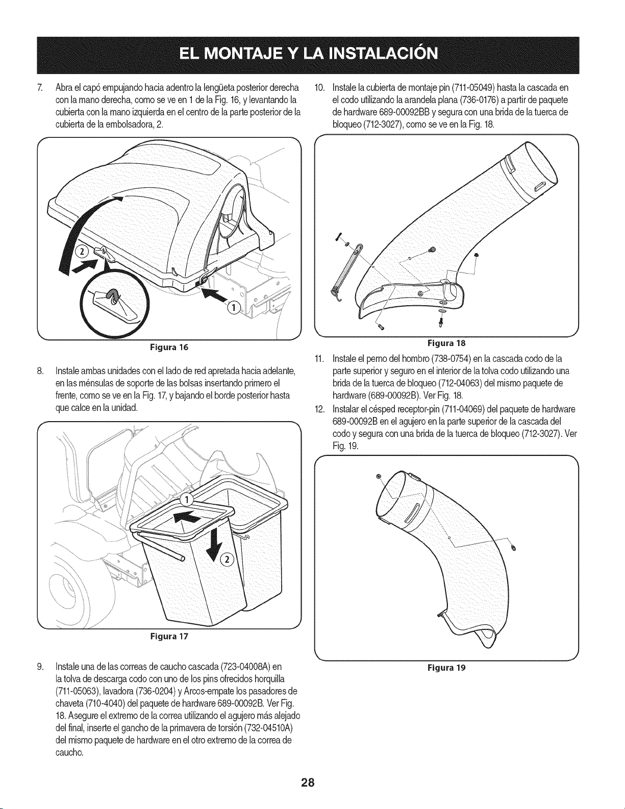
Abraelcap6empujandohaciaadentrolalengietaposteriorderecha
conlarnanoderecha,comoseve en1delaFig.16,y levantandola
cubiertaconla manoizquierdaen el centrode la parteposteriorde la
cubiertade laembolsadora,2.
10.
Instalelacubiertade montajepin(711-05049)hastala cascadaen
elcodoutlizandolaarandelaplana(736-0176)a partirde paquete
dehardware689-00092BBy seguraconunabridadelatuercade
bloqueo(712-3027),comoseve enla Fig.18.
Figura 16
Instaleambasunidadesconel ladode redapretadahaciaadelante,
enlasm_nsulasdesoportedelasbolsasinsertandoprimeroel
frente,comoseveen la Fig. 17,y bajandoel hordeposteriorhasta
quecalceenla unidad.
Figura 17
Instaleunade lascorreasde cauchocascada(723-04008A)en
latolvadedescargacodocon unode lospinsofrecidoshorquila
(711-05063),lavadora(736-0204)y Arcos-empatelospasadoresde
chaveta(710-4040)del paquetede hardware689-00092B.VerFig.
18.Asegureelextremode la correautilizandoel agujerom£salejado
delfinal,inserteelganchodela primaveradetorsi6n(732-04510A)
delmismopaquetede hardwareen el otroextremode la correade
caucho.
Figura18
11. Instaleel pernodelhombro(738-0754)enlacascadacodode la
partesuperiory seguroenelinteriorde latolvacodoutilizandouna
bridadela tuercade bloqueo(712-04063)delmismopaquetede
hardware(689-00092B).VetFig.18.
12. Instalarelc_spedreceptor-pin(711-04069)delpaquetede hardware
689-00092Benel agujeroen la partesuperiorde la cascadadel
codoy seguraconunabridade latuercadebloqueo(712-3027).Vet
Fig.19.
®
Figura 19
J
28
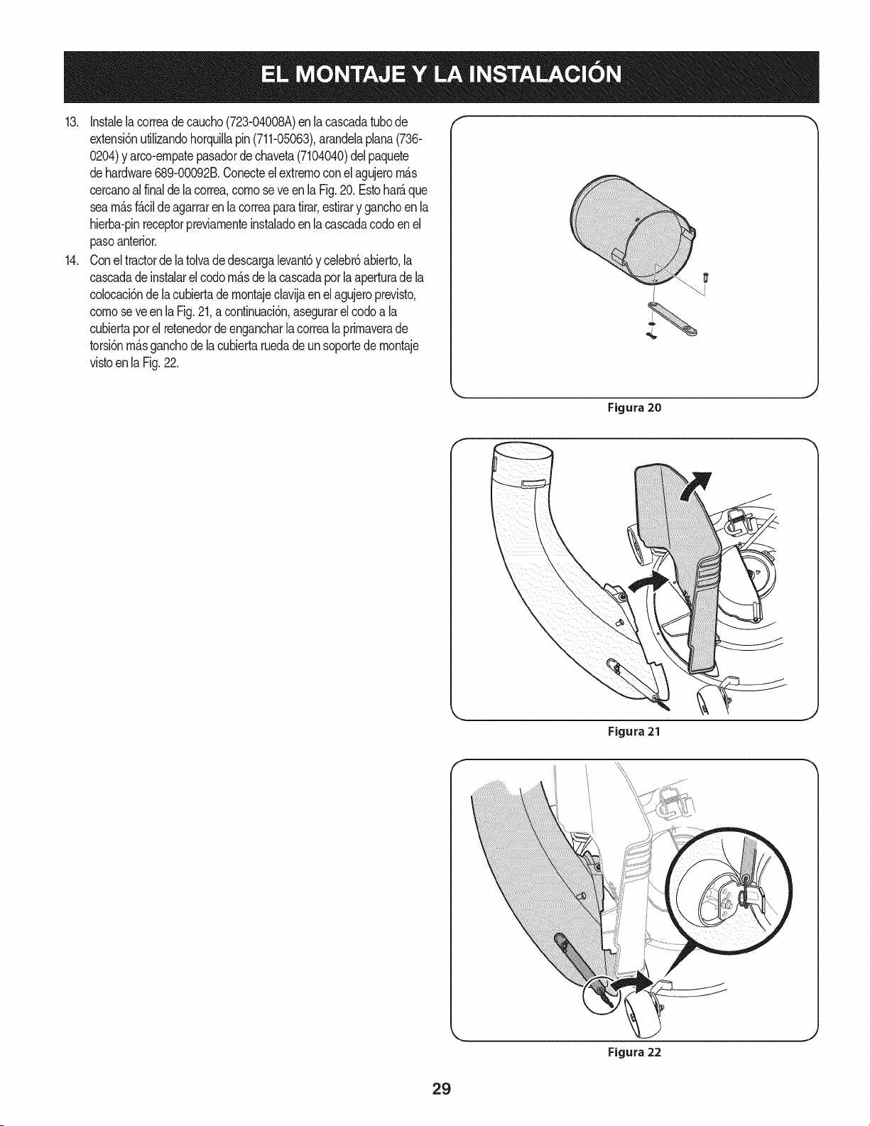
13. Instalelacorreade caucho(723-04008A)en lacascadatubode
extensi6nutilizandohorquillapin(711-05063),arandelaplana(736-
0204)y arco-ernpatepasadorde chaveta(7104040)del paquete
dehardware689-00092B.Conecteel extremoconel agujerom_.s
cercanoalfinaldela correa,comoseveenla Fig.20.Estohar_.que
seam_.sf_.cilde agarraren la correaparatirar,estirary ganchoen la
hierba-pinreceptorpreviamenteinstaladoen la cascadacodoenel
pasoanterior.
14. Conel tractordelatolvadedescargalevant6y celebr6abierto,la
cascadade instalarel codom_.sde la cascadapotla aperturadela
colocaci6nde lacubiertade montajeclavijaen el agujeroprevisto,
comoseveenlaFig.21,a continuaci6n,asegurarelcodoa la
cubiertapot el retenedordeengancharlacorreala primaverade
torsi6nm_.sganchode la cubiertaruedade un soportede montaje
vistoenla Fig.22.
f
Figura 20
Figura21
Figura 22
29

15, Instaleel tubo de extensi6ncascadaen lacascadacodo por el 17,
forrohastalaspestaSasy deslizarel adaptadorde m_.sdela
cascadadelcodo, comoen la Fig,23. Asegureel adaptadorde la
tolvaseextiendeporla cascadade engancharla correay queen
elcesped-pinreceptorinstaladoanteriormente,
Figura 23
16, Quite la partetraserade la cintade espumaautoadhesiva
(desde 721 hasta04,388) que hasido incluida conel colector
de c_sped,Apliqueloen la canaletasuperior,a ras contrala
bridacomose muestraen la figura,24,
7
!
Figura24
Con la hierba receptor de aperturade lacubierta, instalarla
tolvade descargasobrela cascadade extensi6ndeltubo,
comose ve en la Fig, 25, y el restoel extremosuperioren la
parte superiorde la tolva de apoyoinstalado en el ladoderecho
de la bolsa de apoyoa la AsamNea.Ver Fig. 26.
Figura 25
Nora: Aseg_resedealinearel canalsuperiorcon lassalientesdela
m_nsulade soportedel recolector,
Figura 26
30
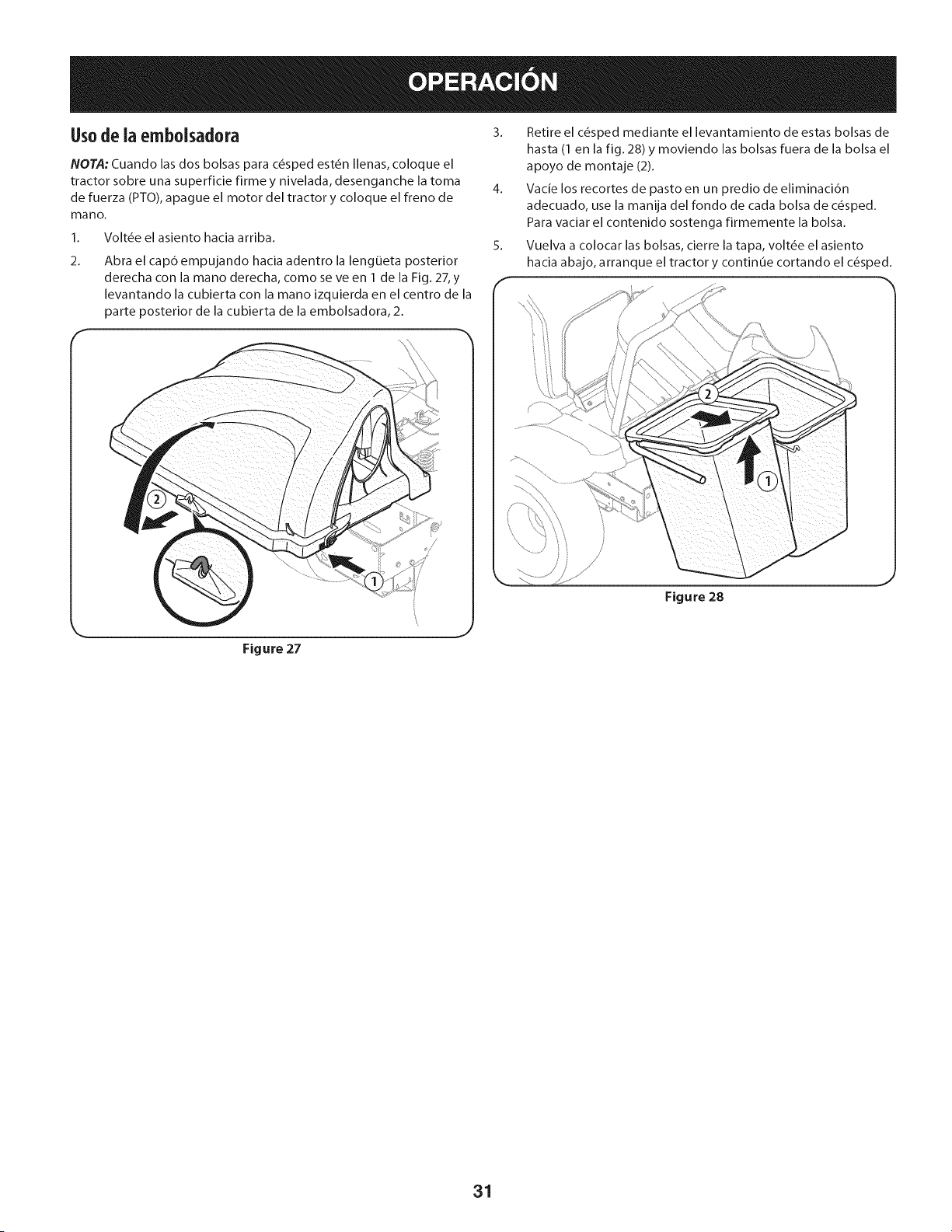
Usode ia embolsadora
NOTA:Cuando las dos bolsas para c_sped est_n Ilenas, coloque el
tractor sobre una superficie firme y nivelada, desenganche la toma
de fuerza (PTO),apague el motor del tractor y coloque el freno de
mano.
1. Volt_e el asiento hacia arriba.
2.
Abra el cap6 empujando hacia adentro la lengOeta posterior
derecha con la mano derecha, como se ve en 1 de la Fig. 27,y
levantando la cubierta con la mano izquierda en el centro de la
parte posterior de la cubierta de la embolsadora, 2.
3. Retire el c_sped mediante el levantamiento de estas bolsas de
hasta (1 en la fig. 28) y moviendo las bolsas fuera de la bolsa el
apoyo de montaje (2).
4. Vacie los recortes de pasto en un predio de eliminaci6n
adecuado, use la manija del fondo de cada bolsa de c_sped.
Para vaciar el contenido sostenga firmemente la bolsa.
5. Vuelva a colocar las bolsas, cierre la tapa, volt_e el asiento
hacia abajo, arranque el tractor y continue cortando el c_sped.
Figure 28
Figure 27
31

Your Home
For troubleshooting, product manuals and expert advice:
managernylife
www.managemylife.com
For repair - in your home - of all major brand appliances,
lawn and garden equipment, or heating and cooling systems,
no matter who made it, no matter who sold it!
For the replacement parts, accessories and
owner's manuals that you need to do-it-yourself.
For Sears professional installation of home appliances
and items like garage door openers and water heaters.
1-800-4-MY-HOME ® (1-800-469-4663)
Call anytime, day or night (U.S.A. and Canada)
www.sears.com www.sears.ca
Our Home
For repair of carry-in items like vacuums, lawn equipment,
and electronics, call anytime for the location of your nearest
Sears Parts & Repair Service Center
1-800-488-1222 (U.S.A.) 1-800-469-4663 (Canada)
www.sears.com www.sears.ca
To purchase a protection agreement on a product serviced by Sears:
1-800-827-6655 (U.S.A.) 1-800-361-6665 (Canada)
Para pedir servicio de reparaci6n
a domicilio, y para ordenar piezas:
1-888-SU-HOGAR ®
(1-888-784-6427)
www.sears.com
Au Canada pour service en frangais:
1-800-LE-FOYER Mc
(1-800-533-6937)
www.sears.ca
® Registered Trademark / TMTrademark of KCD IP, LLC in the United States, or Sears Brands, LLC in other countries
® Marca Registrada ! TMMarca de Fabrica de KCD IP, LLC en Estados Unidos, o Sears Brands, LLC in otros paises
MCMarque de commerce ! MDMarque deposee de Sears Brands, LLC