Loading ...
Loading ...
Loading ...
Installation Step 7
Install the Premium Control Console
and Connect all Wiring
Locate the door control within sight of the door at a
minimum height of 5 feet where small children cannot
reach, and away from all mo,ing parts of the door and
door hardware.
The door control is typically attached directly to the wall.
If installing imo dxywall, drill 5/32" holes and use the
anchors wovided. For plv-wired installations' (as'in new
home consm¢ction), Console models' may be mounted to a
standard single gang box (Figure 2).
1. Strip 1/4" of insulation from one end of the bell wire
madcomaect it to the two screw terlninals on the back of
the door control by color: white to 2 and white/red to 1.
2. Pry off cover along one side with a screwdriver blade
(see Figurel). Fasten with 6ABxl-1/4" self-tapping
screws (standard installation) or 6-32x t" machine
screws (we-wired installation) as follows:
• Install bottoln screw, allowing 1//8" to protrude above
wall surface.
• Position bottom of door control on screw head and
slide down to secure. Adjust screw for snug fit.
• Drill and install top screw with care to avoid cracking
plastic housing. Do not overtighten.
• Insert top tabs and snap on cover.
3. (For standard installation only) Run the bell wire up the
wall and across the ceiling to the opener. Use insulated
staples to secure the wire in several places. Be careful
not to pierce the wire with a staple, creating a short. If
),our access door is'near the garage doot; you may lwn
th# wire with the Safe O,Reversing ,Sensor wires along
the top of the rail. Seepage 18.
4. Relnove the Control Center door on the right panel of
the opener to access the terlninal screws.
5. Thread all wires tlmmgh the opening at the base of the
drive shaft cover (see Figure 3).
6. Insert the relnaining wire tl_ough the hole in the power
unit and strip 1/4" of insulation froln each set of wires.
7. Connect the door comrol wire to the opener terlninal
screws: white to 2 and white/red to 1. (See Figure 4.)
8. Separate the sensor white and white/black wires
sulliciently to connect to the opener terminal screws:
white to 2 and white/black to 3.
9. Attach the User Safety Instruction label to the wall near
the door control, and the Maimenance Instruction label
in a prolninent location on the inside of the garage door.
Page 32 explains how to operate the opener using the
door control.
Hardware Shown Actual Size
!I'I'2; Ii!;'>
Control Console (std installation)
'""'2Z',!'2w
Controt Console (we-wired)
Insulated
Staples
Dry Wall Anchors
21
Do not connect to live electrical wiring. Connect only to 24 Volt
low voltage wires. Connection to live wires or higher v oltage
may cause serious injury from shock, burn or electrocution.
Children operating or playing with a garage door opener can
injure themselves or others. The garage door cou/d c/ose and
cause serious injury or death.
Install the door control (or any additional push buttons) out of
the reach of children and away from all moving parts of the
door and door hardware, but where the garage door is visible.
Do not allow children to operate the push b utton(s) or the
remote control(s).
A moving garage door could injure someone under it. Activate
the opener only when the door is properly adjusted, you can
see it clearly, and there are no obstructions to door travel.
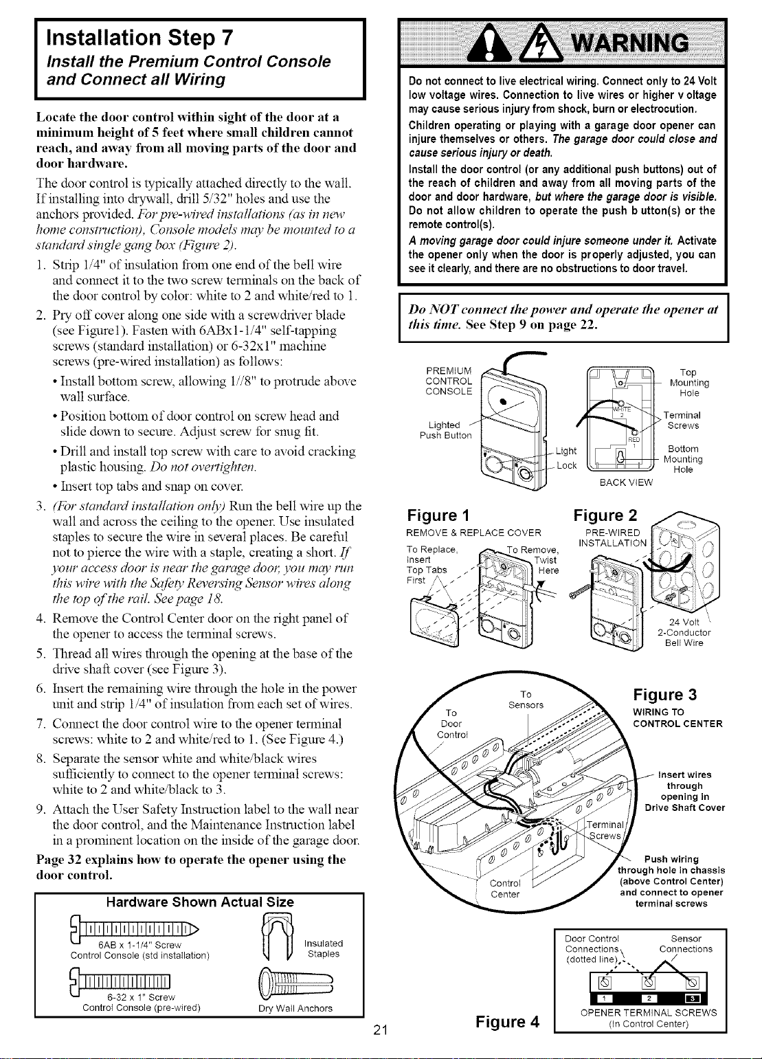
Do NOT eonneet the power and operate the opener at
this time. See Step 9 on page 22.
PREMIUM
CONTROL
CONSOLE
Lighted
Push Button
/
Light
Lock
Figure 1
REMOVE & REPLACE COVER
To Replace, (,,"_,._o Remove,
Insert J_-_ _ Twist
Top Tabs _ _ _1_ _]} Here
i it ;
BACK VIEW
Figure 2
PRE-WIRED
INSTALLATION
Top
Mounting
Hole
Terminal
Screws
Bottom
Mounting
Hole
24 Volt
2-Conductor
Bell Wire
Figure 3
WIRING TO
CONTROL CENTER
Insert wires
through
opening in
Drive Shaft Cover
Push wiring
through hole in chassis
(above Control Center)
and connect to opener
terminal screws
Figure 4
Door ControI Sensor
Connections\ Connections
(dotted line)o_ ", ,_
OPENER TERMINAL SCREWS
(In Controt Center)
Loading ...
Loading ...
Loading ...