Loading ...
Loading ...
Loading ...
11
Heater Assembly Replacement
Tools Required: Phillips-Head Screwdriver
Pliers
1. Follow the instructions for Preparing Firebox for Service on page 10.
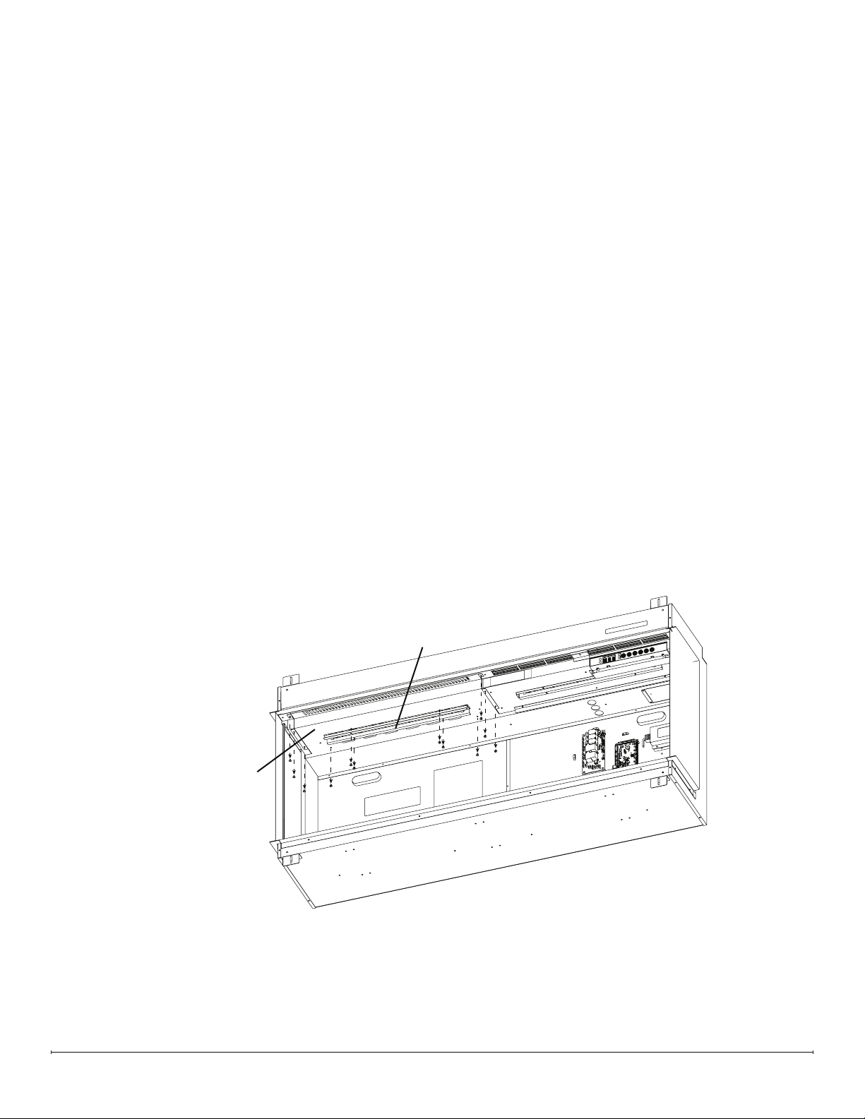
2. Remove the 4 screws that secure the overhead LED assembly. Unplug the LED connection, and set the assembly
aside (Figure 5).
3. Remove the 8 screws around the perimeter of the heater assembly panel (Figure 5).
4. Push the heater assembly toward the back of the replace. It will move about 1/2 inch.
5. Hold the heater assembly front edge and lower the heater assembly.
6. Trace the connections from the heater assembly to the relay board. Carefully disconnect the connections, noting
their original locations. Cut any restrictive wire ties.
7. Remove the defective heater assembly.
8. Feed the wires, one at a time, from the new heater assembly through the top portion of the housing to make the
connections on the relay board.
9. Connect the wires from the heater assembly to the correct locations on the relay board.
10. Secure the wires using the provided wire ties and ensure they are pushed back as to not be too close to the back of
the mirrored glass.
11. Position the new heater assembly by aligning the back of the bracket in the top housing and tilting it upward. Ensure
the LED wire is fed through the slot for the LED assembly
12. Pull the heater assembly forward to align the screw holes. Secure using the previously removed screws.
13. Connect the LED wire, ensuring the IN marking on the board is oriented toward the right side. Secure the LED
assembly.
Heater Assembly
(Includes panel)
Overhead LED
Assembly
Figure5
Loading ...
Loading ...
Loading ...