
Dishwasher
Installation Manual
USA
Document Number :
15 9889 0100_BEKO_USA/ 29-11-22.(17:28)
Installation Manual
DDN25401X
DDN25402W
DDN25402X
DDT25401B
DDT25401W
DDT25401X
DDT36430X
DDT36430XIH
DDT38530BX
DDT38530X
DDT38530XIH
DDT38530X WS
DDT38532X
DDT38532XIH
DDT39432CF
DDT39432X
DDT39432XIH
DDT39434CF
DDT39434X
DDT39434XIH
DIN25401
DIT25401
DIT38530
DIT38532
DIT39432
DIT39434
DUT25401B
DUT25401W
DUT25401X
DUT36420W
DUT36420X
DUT36520W
DUT36520X
DUT36522W
DUT36522X
DDT38532X WS
DIT39434C2
DDT39434XC2
DDT39434XIHC2
DIT38532 WS
DDT38532XIH WS
DUT25401XHW
DUT25401WHW
DUT25401BHW
DDT38532XHW
DDT38532XIHHW

INTRODUCTION 1
1. IMPORTANT SAFETY INSTRUCTIONS 1
1.1 INSPECT THE DISHWASHER 2
2. TOOLS WHICH MAY BE NEEDED 3
3. MATERIALS WHICH MAY BE NEEDED 3
4. MATERIALS SUPPLIED 4
4.1 PARTS SUPPLIED 4
4.2 MANUAL BAG 4
4.3 DISHWASHER PARTS BAG 1 4
4.4 DISHWASHER PARTS BAG 2 4
4.5 PARTS ATTACHED TO THE REAR OF THE DISHWASHER 4
5. DISHWASHER SPECIFICATIONS 5
5.1 TECHNICAL FEATURES 6
6. ENCLOSURE PREPARATION 7
6.1 ELECTRICAL PREPARATION 7
6.2 PREPARATION FOR INSTALLING MOUNTING BRACKETS 7
6.3 ADJUSTING HEIGHT 10
6.4 INSTALLING THE SIDE TRIM STRIPS 11
6.5 PREPARING THE WATER CONNECTION (A) 11
6.6 DRAIN PREPARATION 12
6.7 STEAM PROTECTION FOIL 14
7. PLACEMENT OF DISHWASHER INTO THE OPENING 15
7.1 DRAIN HOSE CONNECTION, WATER SUPPLY & ELECTRICAL CONNECTIONS 15
7.2 READJUSTING FOOT LEVELS 18
7.3 ADJUSTING THE MOVABLE TOE KICK 18
7.4 FIXING THE CABINET TO THE COUNTER 20
7.5 PREPARING THE TIMBER DOOR 22
7.6 PREPARING THE PRODUCT DOOR 23
7.9 INSTALLING THE TIMBER DOOR 24
7.10 FIXING THE TIMBER DOOR 24
7.11 FIXING THE TIMBER DOOR 25
7.12 ADJUSTING THE KICK PLATE 25
7.13 CONNECTION 26
8. INSTALLER CHECKLIST 27
9. SELF HELP HINTS: 27
To prevent accidents, which could cause serious injury or death, as well
as machine damage read these instructions before installation and / or
use.
1
USA
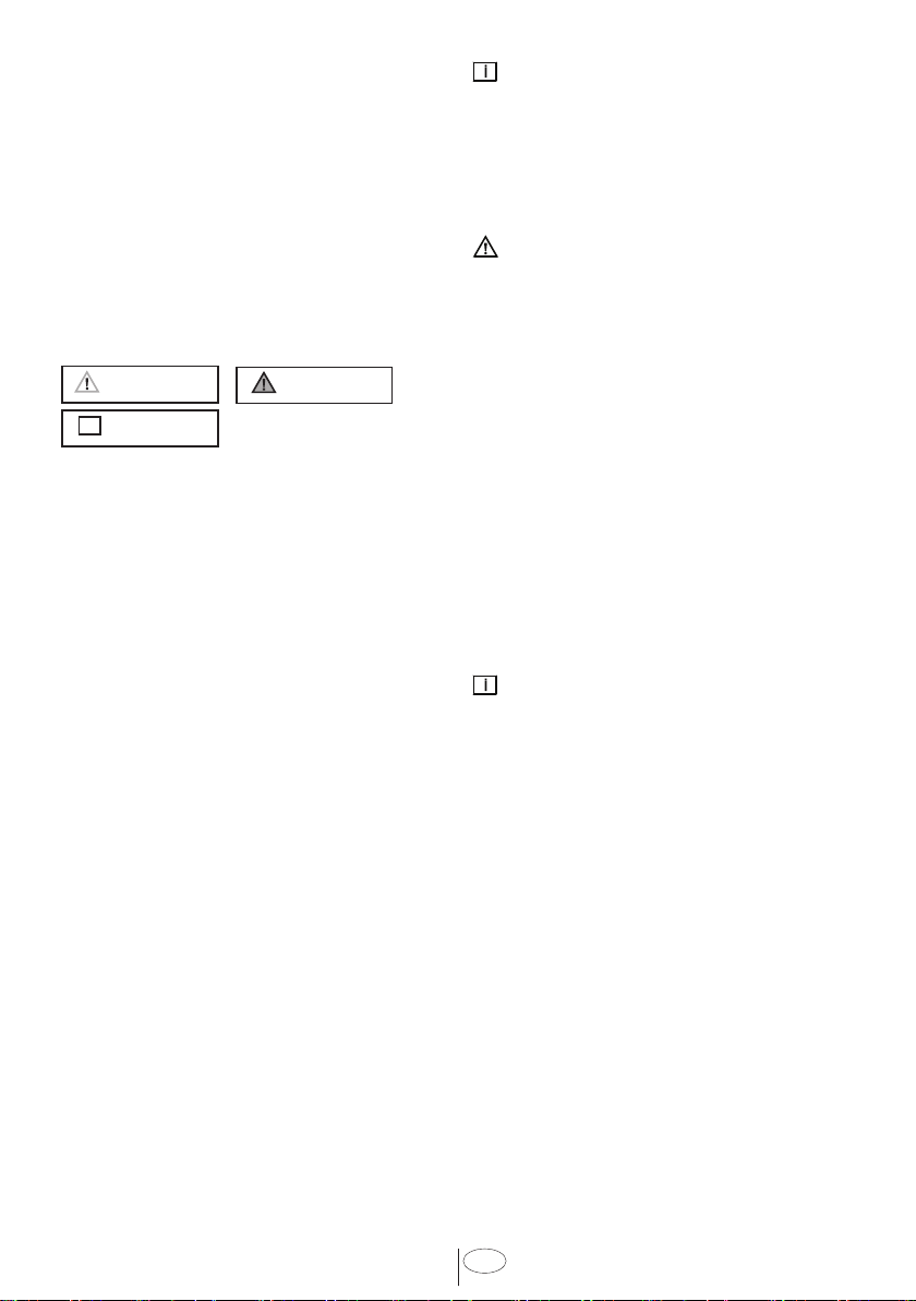
INTRODUCTION
Please read ths nstallaton manual
and partcularly the safety nstructons
completely and carefully. They wll save you
tme and effort and help to ensure optmum
dshwasher performance.
Be sure to observe all lsted warnngs and
cautons. Look partcularly for the cons wth
exclamaton marks nsde. The nformaton
con also wll provde mportant references.
WARNING:
Indcates a potentally hazardous stuaton
whch, f not avoded, could result n death
or serous njury.
CAUTION:
Indcates a potentally hazardous stuaton
whch, f not avoded, may result n njury.
It may also be used to alert aganst unsafe
practces.
NOTICE:
Indcates a potentally hazardous stuaton
whch, f not avoded, may result n damage
to the dshwasher, the table-ware, the
equpment or the envronment.
1. IMPORTANT SAFETY
INSTRUCTIONS
In addton to these nstructons, the
dshwasher shall be nstalled:
• In accordance with all local codes or, in
absence of a local code,
• In the United States, with the National
Electric Code,
• In Canada, with the Canadian Electric
Code C22.1-latest edition/Provincial
and Municipal codes and/or local codes.
NOTICE :
Read these nstallaton nstructons
completely before nstallng and follow
them carefully. Save these nstallaton
nstructons and pass them on to any
future user.
WARNING
When installing the dishwasher,
follow basic precautions, including
the following:
• The dishwasher could only be
converted from cord-connected
to permanently connected by an
authorized service representative.
(If needed contact your dealer to
schedule an authorized service agent
for conversion with an appropriate
conversion kit)
• Installation and repair should be
performed by a qualified installer.
Work by unqualified persons could be
dangerous and may void the warranty.
NOTICE :
The dshwasher should be nstalled by an
nsured lcensed plumber, contractor or
traned nstaller. Installaton performed
by persons other than ths could result n
mproper nstallaton and property damage.
• Do not operate the appliance if
damaged, malfunctioning, partially
disassembled or if it has missing or
broken parts.
• Also follow the safety instructions of
the user manual.
• To reduce the risk of electric shock,
fire, or injury to persons, the installer
must ensure that the dishwasher is
completely enclosed at the time of
installation.
• Only connect the dishwasher to the
power supply when all installation and
plumbing work is complete.

2
USA
• If the dishwasher is installed in a
location that experiences freezing
temperatures (e.g. in a vacation home,
cabin, etc.), you must drain all the
water from the dishwasher’s interior.
Water system ruptures that occur as
a result of freezing are not covered by
warranty.
• Dishwasher must be secured to
adjacent cabinetry using the brackets
provided. Failure to do this may cause
damage to property or bodily injury.
• Connect to a properly rated, protected
and sized power supply circuit to avoid
electrical overload. The dishwasher
is designed for an electrical supply
of 120 V (volts), 60 Hz (hertz), AC,
connected to a dishwasher-dedicated,
properly grounded electrical circuit
with a fuse or breakers rated for 15
amperes. Electrical supply conductors
shall be a minimum of # 16 AWG
copper wire rated at 75 °C (167 °F) or
higher. These requirements must be
met to prevent injury and machine
damage. Consult a qualified electrician
if in doubt.
• Do not use any extension cord or
portable outlet device to connect the
dishwasher to a power supply.
• Ensure that any plastic wrappings,
bags, small pieces etc. are disposed
of safely and kept out of the reach of
children. Danger of suffocation!
• Remove the door to the washing
compartment when removing an old
dishwasher from service or discarding
it. Ensure that the appliance presents
no danger to children while being
stored for disposal.
• Old appliances may contain materials
that can be recycled. Please contact
your local recycling authority about
the possibility of recycling these
materials.
NOTICE :
• The dishwasher drain hose must be
installed with a drain loop at least
28” (710mm) off the cabinet floor;
otherwise the dishwasher may not
drain properly.
• This dishwasher is intended for
residential use only, and should not be
used in commercial establishments.
• New installation - If the dishwasher is
a new installation, most of the work
must be done before the dishwasher is
moved into place.
• Replacement - If the dishwasher is
replacing another dishwasher, check
the existing dishwasher connections
for compatibility with the new
dishwasher, and replace parts as
necessary.
1.1 INSPECT THE DISHWASHER
After unpackng the dshwasher and pror
to nstallaton, thoroughly nspect the
dshwasher for possble freght or cosmetc
damage. Report any damage mmedately.
NOTICE :
• Cosmetic defects must be reported
within 10 days of installation.
• Do not discard any bags or items that
come with the original package until
after the entire installation has been
completed.
3
USA
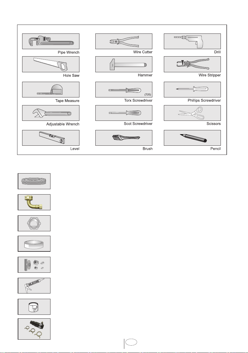
2. TOOLS WHICH MAY BE NEEDED
3. MATERIALS WHICH MAY BE NEEDED
(Addtonal materals may be requred to comply wth local codes)
Hot Water Supply Lne - Mnmum 3/8” O.D. copper tubng or metal braded
dshwasher supply lne.
Elbow wth 3/4” FHT(female threaded) for dshwasher sde, and szed to
ft your water supply lne (copper tubng/compresson fttng, or braded
hose) on the other sde. Dshwasher connecton s 3/4” male.
UL lsted condut connector or stran relef.
Teflon tape or other ppe thread compound to seal plumbng connectons.
Shut-off valve and fttngs approprate for hot water supply lne (copper
tubng/compresson fttng, or braded hose).
Slcone
Glue
Dshwasher Dscharge Hose Adaptor
4
USA
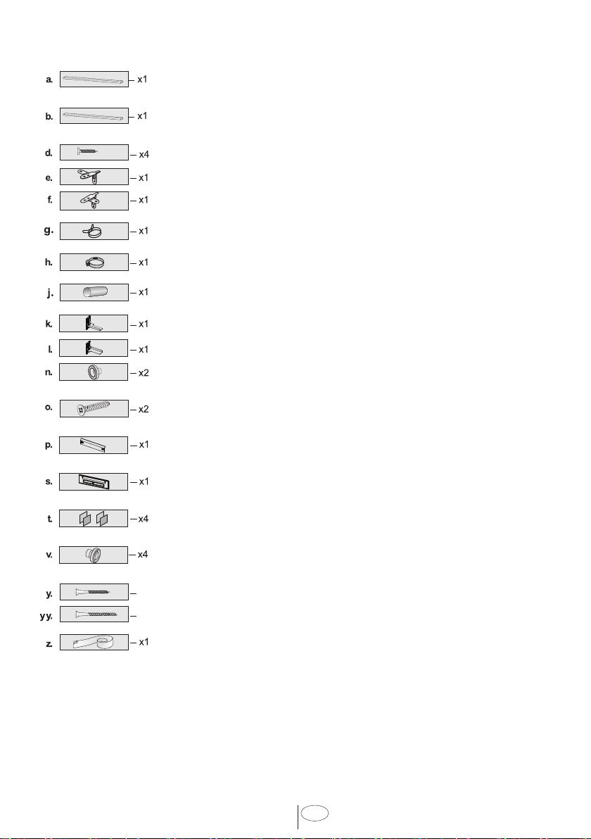
4. MATERIALS SUPPLIED
4.1 PARTS SUPPLIED
Parts for your dshwasher wll
come n several plastc bags.
Check your parts bags shown
to make sure you have all the
parts as lsted to the left.
4.2 MANUAL BAG
The dshwasher comes wth a
manual bag contanng:
• User manual,
• Installation manual
4.3 DISHWASHER
PARTS BAG 1
Ths dshwasher bag comes
wth the followng parts:
a.
Sde Trm Strps (Left)
b.
Sde Trm Strps (Rght)
d.
Screws Ø 1/8” x 5/8” (Ø 3.5
mm x 14 mm)
e.
Mountng Bracket Left
f.
Mountng Bracket Rght
g.
Sprng Clamp
h.
Screw Clamp
j.
Rubber Connector
k.
Toe Kck Bracket - Left
l.
Toe Kck Bracket – Rght
n.
Tmber Centerng
o.
Tmber Centerng Screw
p.
Toe Kck
s.
Template
t.
Hook and loop fastener
v.
Sde centerng
z.
Steam Protecton Fol
4.4 DISHWASHER
PARTS BAG 2
(MODEL DEPENDING)
In addton to the manual bag
and the dshwasher parts bag
(dshwasher models whch
can accept a wooden ktchen
door) also come wth a door
panel nstallaton kt whch
contans:
y.
Screws 4mm x 36 mm =
3/16th x 1-7/16th
yy.
Screws Ø 3/16” x 13/4” (Ø
4mm x 43mm)
4.5 PARTS
ATTACHED TO
THE REAR OF THE
DISHWASHER
a.
Sde Trm Strps (Left)
b.
Sde Trm Strps (Rght)
x4
x2
5
USA
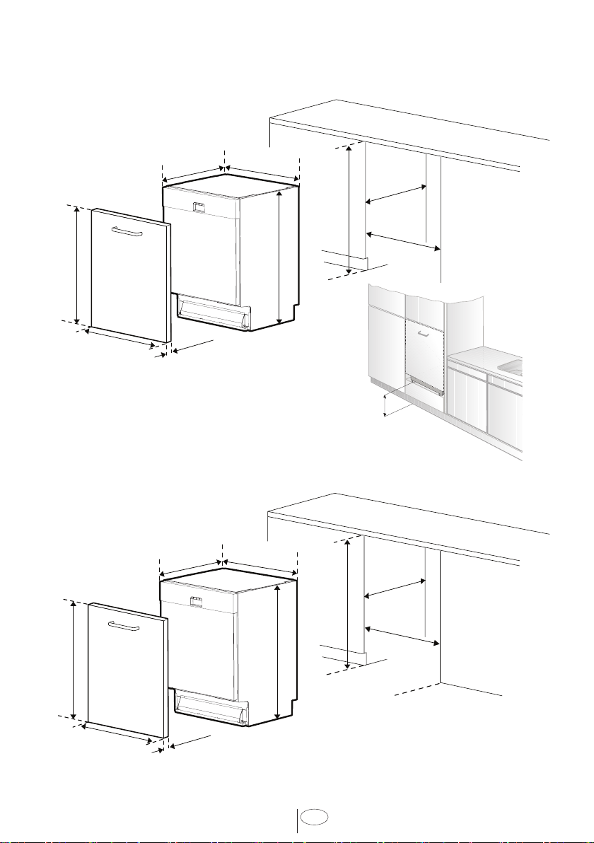
5. DISHWASHER SPECIFICATIONS
TALL TUB MODELS
STANDARD TUB MODELS
24”
(610 mm)
34” - 35
”
(864 mm - 913 mm)
23 ⅝ “ - 24“
(600 mm - 610 mm)
(550 mm)
21 ⅝”
(598 mm)
23 ⁄”
33 ⅞” - 35 ⅞”
(861 mm - 911 mm)
(592 mm - 603 mm)
23 ⁄ “ - 23 ⁄ “
(700 mm - 760 mm)
27 ⁄” - 29 ⁄”
⁄” Min.
(18 mm)
Min. 6.6 lbs (3 kg)
Max. 19.8 lbs (9 kg)
24”
(610 mm)
32 ⁄” - 36
⁄
”
(820 mm - 920 mm)
23 ⅝ “ - 24“
(600 mm - 610 mm)
(550 mm)
21 ⅝”
(598 mm)
23 ⁄”
32 ⁄” -36 ⁄ ”
(818 mm - 918 mm)
(592 mm - 603 mm)
23 ⁄ “ - 23 ⁄ “
(660 mm - 720 mm)
26” - 28 ⁄”
Min. 6.6 lbs (3 kg)
Max. 19.8 lbs (9 kg)
⁄” Min.
(18 mm)
19 11/16”
max
500mm

6
USA
5.1 TECHNICAL FEATURES
Permissible water
pressure
4.35 - 145 ps (0.3 - 10 bars)
Electrical connection
120 V (volts), 12 A (amps), 60Hz (hertz)
Total power
1400 W (watts)
Heater power
1100 W (watts)
NOTICE :
Because we contnually strve to mprove our products, we may change our specfcatons
and desgn wthout pror notce.
Ths devce corresponds to the followng drectves:
UL 749 Household Dshwasher drectve.
7
USA
6. ENCLOSURE PREPARATION
6.1 ELECTRICAL PREPARATION
WARNING
The dishwasher is designed for an electrical supply of 120 V, 60 Hz, AC,
connected to a dishwasher-dedicated, properly grounded electrical circuit
with a fuse or breaker rated for 15 amperes.
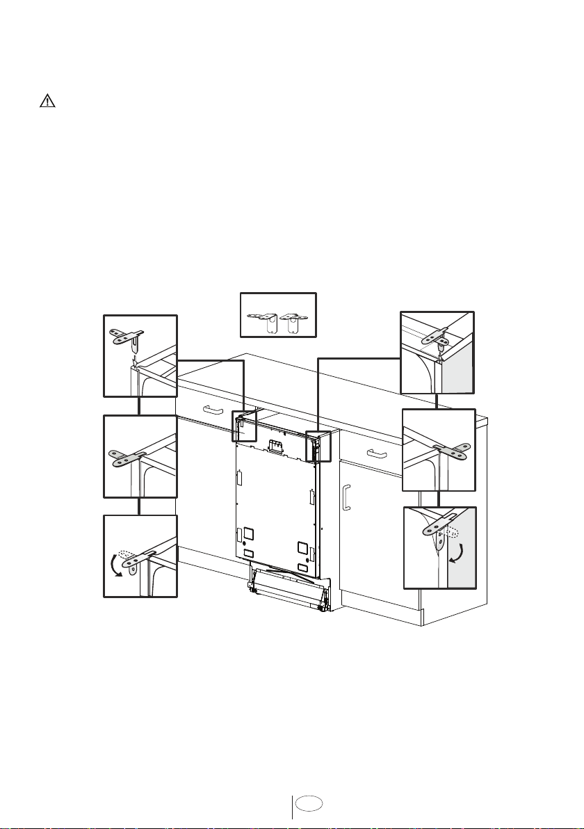
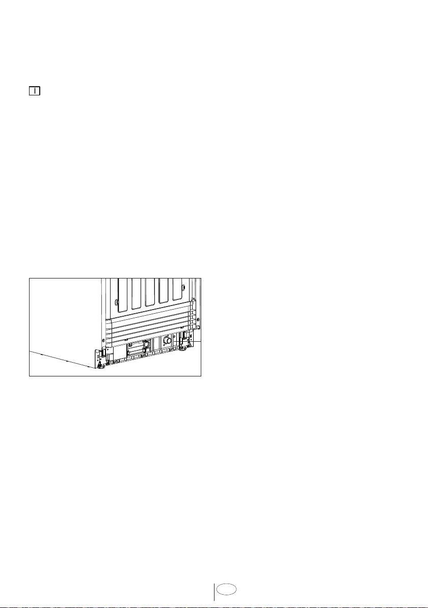
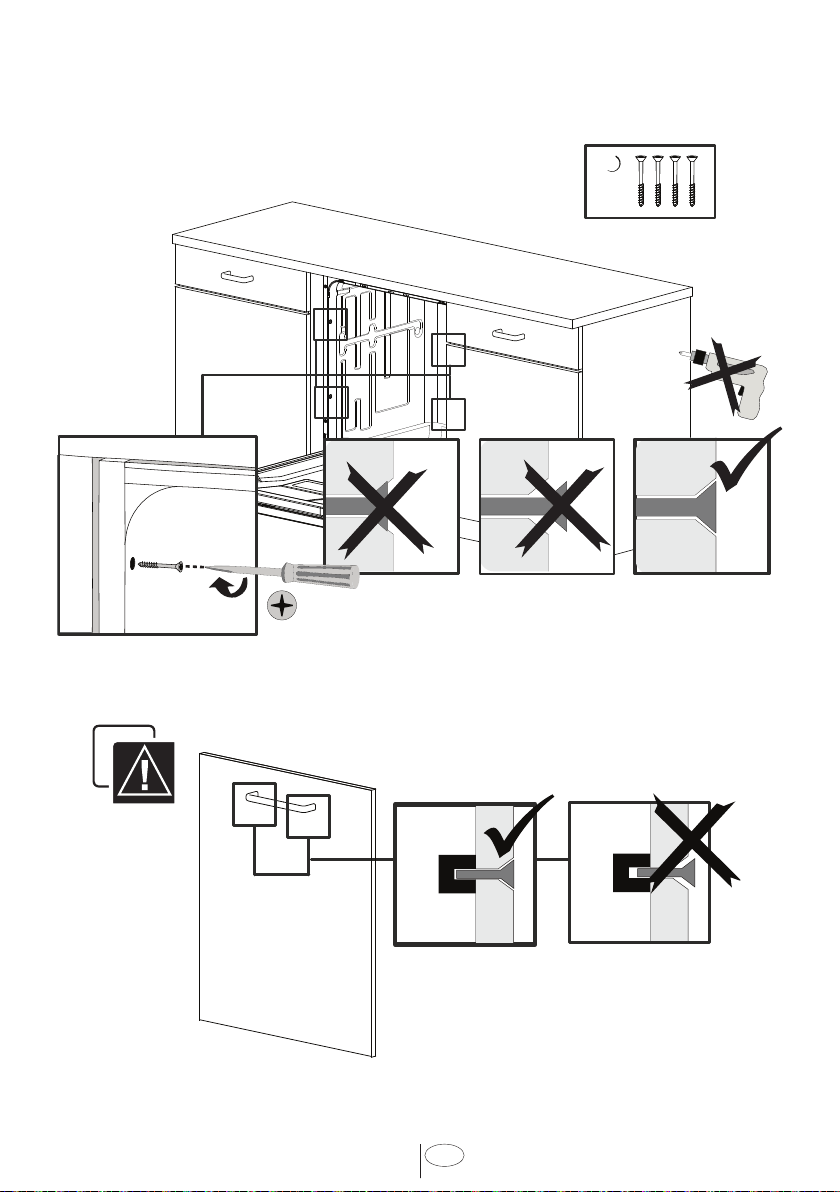
6.2 PREPARATION FOR INSTALLING MOUNTING BRACKETS
e-f)
STANDARD TUB MODELS
8
USA
?
d)
9
USA
(+50mm)
j
+ 50
max
50
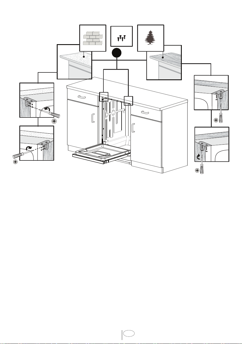
WARNING
Dishwasher must be secured to adjacent cabinetry using the mounting
brackets provided. Failure to do this may cause damage to property or
bodily injury.
(Depends on model)
Tghten the plugs on both
sdes of your machne (v)
TALL TUB MODELS ONLY
10
USA
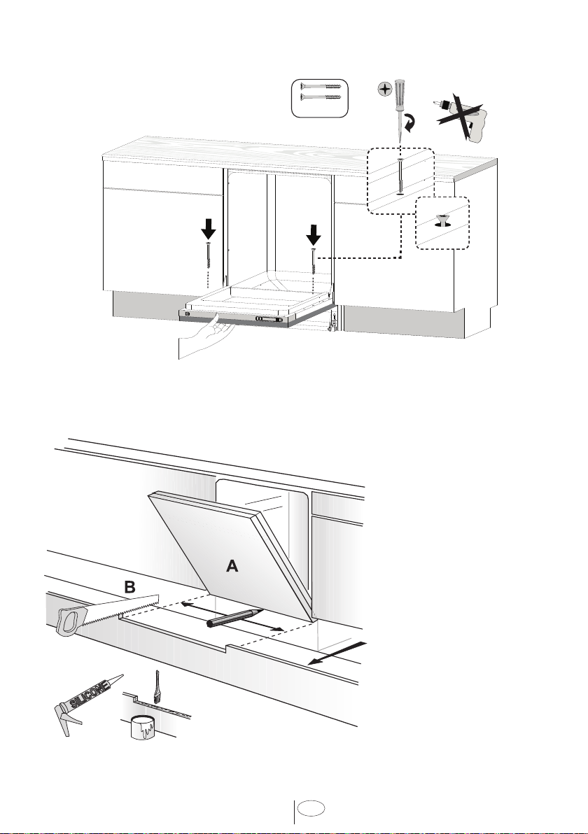
Place the two mountng brackets nto the top
corners of the dshwasher.
Fx the mountng brackets (
A
) to the top corners
of the dshwasher, wth the screws suppled.
Bend sdes of mountng brackets (
B
) n order to
fx from sdes (f necessary).
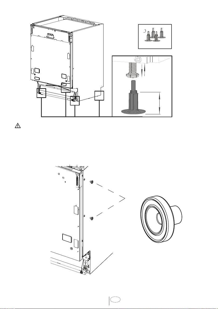
6.3 ADJUSTING HEIGHT
If the heght of the enclosure s 337/8” to 357/8”
(861 mm - 911mm) adjust supports as shown n
the fgure.
Suppled (
4
)
Adjust the front foot level wth the adjustng
wrench to balance and rase the dshwasher to the
enclosure heght.
Adjust the rear foot level wth a screwdrver to
balance and rase the dshwasher to the enclosure
heght.
NOTICE :
• Make sure the dishwasher is plumb and
notice dishwasher can be placed with a small
clearance under the counter top.
• Turning the screwdriver in the direction of
the black arrows will bring the dishwasher
back feet up.
• Turning the screwdriver in the direction of
the white arrows will take the dishwasher
rear feet down.
11
USA
6.4 INSTALLING THE SIDE TRIM STRIPS
Remove the adhesve tape (Fgure
A
).
Place the trm strps on the front edge of the sde walls (Fgure
B
).
NOTICE :
• Make sure you use the correct trim strip since there is a left and right side strip. The
flexible material should be facing forward (Figure
B
).
6.5 PREPARING THE WATER CONNECTION (A)
Install an easly accessble shut-off valve (not suppled) n the water supply lne. All solder
connectons must be made before the water lne s connected to the dshwasher’s water
nlet valve. Water can also be suppled to the dshwasher by usng a flexble braded hose
lne.
Check wth your plumbng supply sources for the proper hose and elbow and necessary
fttngs for the water supply lne. Ths materal s not suppled, and must be purchased
separately.
Water Connection
12
USA
WARNING
Installation should be performed by a qualified installer. Work by unqualified
persons could be dangerous and may void the warranty.
If the dishwasher is installed in a location that experiences freezing
temperatures (e.g. in a vacation home, cabin etc.), you must drain all the
water from the dishwasher’s interior. Water system ruptures that occur as a
result of freezing are not covered by warranty.
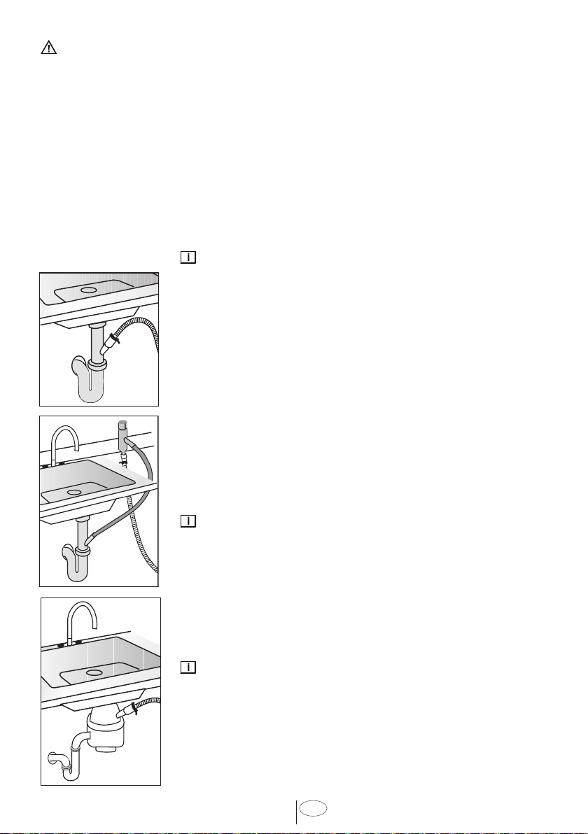
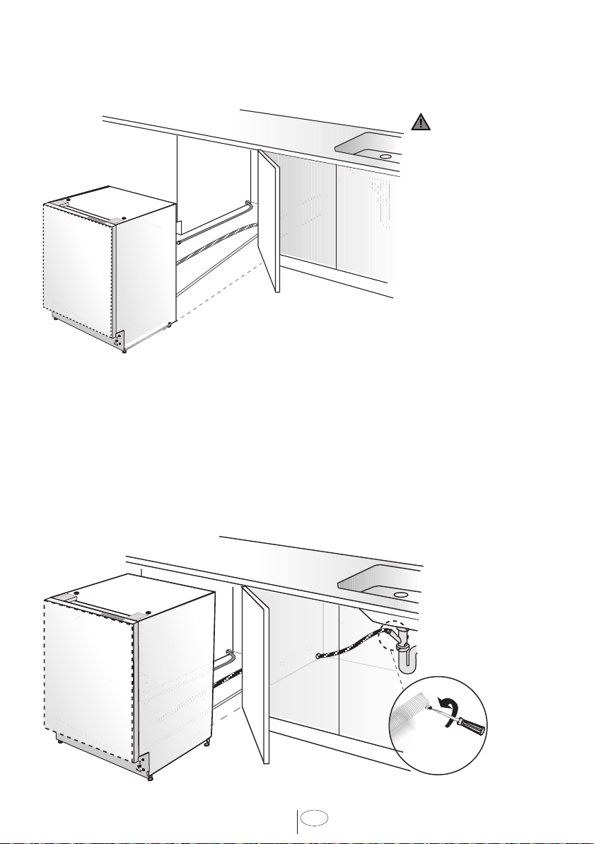
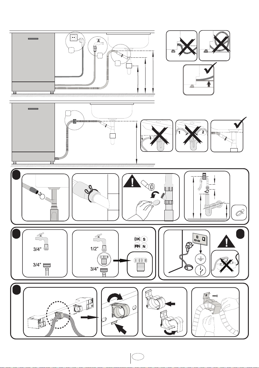
6.6 DRAIN PREPARATION
The dshwasher dran hose may be connected to the dran plumbng n one of three ways
(Fgure
A
,
B
,
C
).
NOTICE :
• Either one of the above methods must be used or the
dishwasher will not operate properly.
• A hose that attaches to a sink spray can burst if it is installed
on the same water line as the dishwasher. If your sink has
one, it is recommended that the hose be disconnected and
the hole plugged.
• The total length of the drain hose is 763/4” (1950mm). If a
hose extension is required, a drainage hose of equal quality
must be used.
• The maximum length must not exceed 157 ½” (4000mm).
Otherwise, the cleaning process is negatively influenced.
6.6.1 UNDER THE SINK DRAIN
Install a Y-branch tal ppe. (Fgure
A
)
NOTICE :
You must add a loop at least 28” (710mm) above the floor of
the cabnet and above the dran connecton n the dran hose to
prevent waste water from not dranng properly, and causng
ether poor washng results or a bad odor.
6.6.2 INSTALLING AN AIR GAP
If the local ordnance requres an ar gap (Fgure
B
).
NOTICE :
Check wth local ordnance for type of ar gap requred.
6.6.3 DISPOSAL
Remove the dran connecton plug before attachng the dran
hose from the dshwasher.
Every dsposal has a hook up for a dshwasher; consult your
dsposer manual for correct connecton. (Fgure
C
)
13
USA
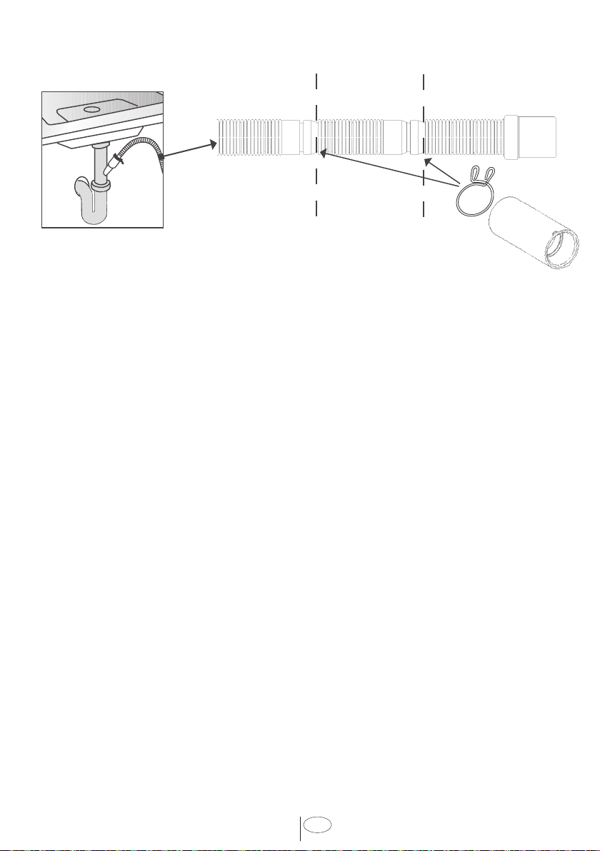
6.6.1 UNDER THE SINK DRAIN (ALTERNATIVE)
•
•
•
•
Due to the local bu�ld�ng code requ�rements, some d�shwasher �nstallat�ons requ�re hook�ng
up d�scharge hose to an a�r gap located next to the s�nk �n k�tchens. S�nce the connect�on
d�ameter �s d�fferent than standard d�scharge hose connect�ons, please use the connector
p�ece prov�ded w�th the mach�ne w�th �nstruct�ons �llustrated.
6.6.1 DESAGÜE DEBAJO DEL FREGADERO (ALTERNATIVO)
•
•
•
•
Deb�do a los requ�s�tos del cód�go de construcc�ón local, algunas �nstalac�ones de
lavavaj�llas requ�eren conectar la manguera de descarga a un espac�o de a�re s�tuado junto
al fregadero en las coc�nas. Dado que el d�ámetro de la conex�ón es d�ferente al de las
conex�ones de manguera de descarga estándar, ut�l�ce la p�eza de conex�ón sum�n�strada
con la máqu�na que cont�ene las �nstrucc�ones que se �lustran a cont�nuac�ón.
14
USA
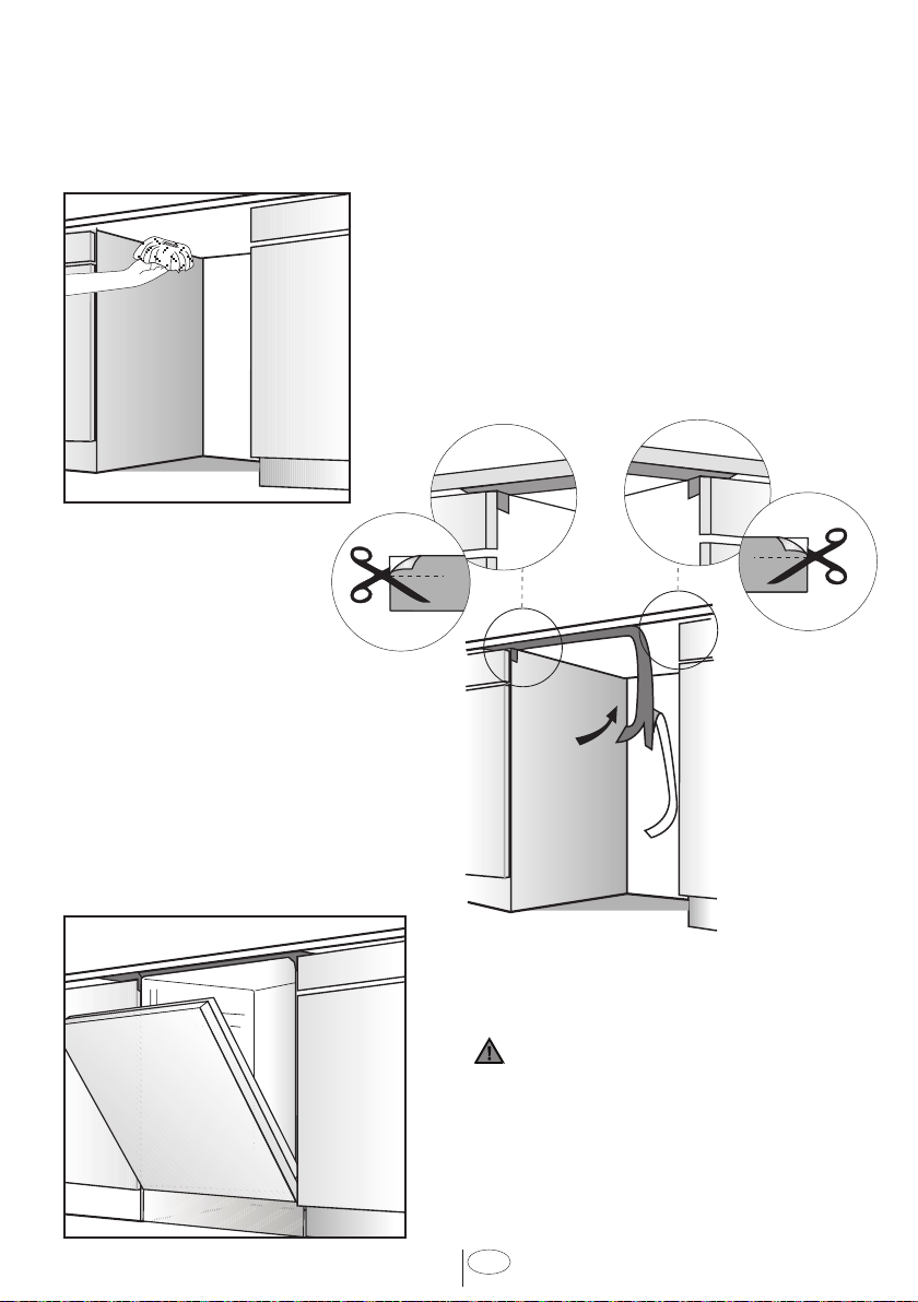
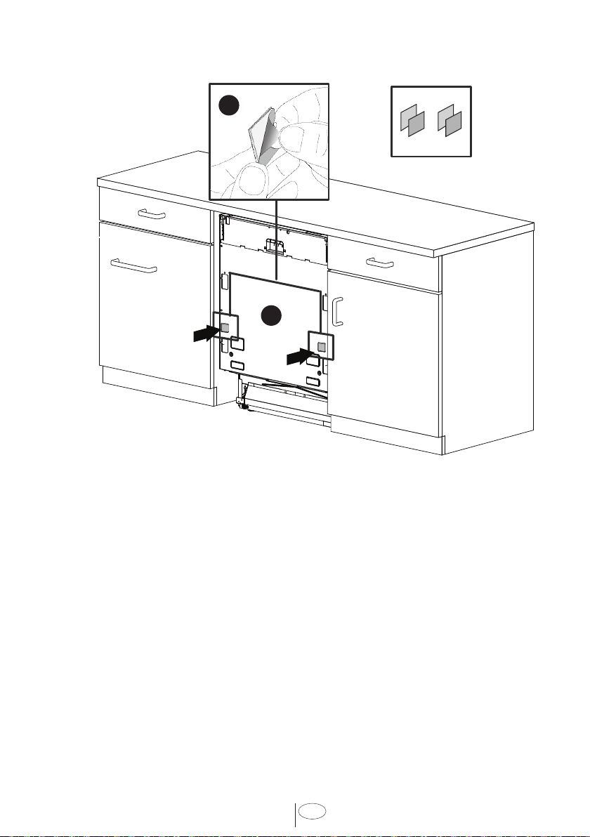
6.7 STEAM PROTECTION FOIL
Steam wll form nsde the dshwasher durng operaton. At the end of the cycle, when
the dshwasher door s opened, t s requred to use a steam protecton fol to prevent any
steam from collectng on the undersde of the counter top.
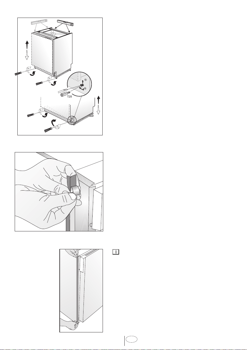
6.6.2 FITTING THE PROTECTION FOIL
Before applyng the steam protecton fol to the
undersde of the countertop, clean the area wth
a damp cloth (as shown n Fgure
A
). Once the
area dres, apply the steam protecton fol.
CAUTION
Steam protecton fol must be appled
where the steam escapes when door s frst
opened.
Failure to install the steam
protection foil during installation can
lead to damage to the cabinets and
countertop.
The steam protecton
fol wll be appled at the
locaton where the hot
steam escapes when you
frst open the door (as
shown n Fgure
B
).
15
USA
7. PLACEMENT OF DISHWASHER INTO THE OPENING
Now place the dshwasher nto the openng and get ready to connect all hoses and
electrcal connectons.
CAUTION
Make sure all hoses
are pulled through
the side opening
of the cabinet, no
hoses are kinked
and all slack is taken
out as shown in the
above figure.
7.1 DRAIN HOSE CONNECTION, WATER SUPPLY & ELECTRICAL
CONNECTIONS
7.1.1 DRAIN HOSE CONNECTION
Connect the dran hose to the dran plumbng.
1. Use the suppled rubber connecton hose and dran hose clamps to connect the
dshwasher dran hose to the plumbng dran connecton.
2. Use the sprng clamp to secure the rubber connecton hose to the dshwasher dran
hose. Use the screw clamp to secure the rubber connecton hose to the plumbng dran
connecton.
Note that the marks
on the rubber
connecton hose
should be on the
dran hose sde

16
USA
7.1.2 WATER SUPPLY CONNECTION
Water supply may be connected to the
dshwasher n one of two ways:
• With metal braided hose.
• With copper tubing.
CAUTION
• Hot water supply line: Use minimum
3/8” O.D. copper tubing or metal
braided dishwasher supply line.
• Temperatures required for soldering
and sweating will damage the
dishwasher’s water inlet valve so if
any such operation is needed, keep
the heat source min. 77/8” (200mm)
away from the dishwasher’s water
inlet valve.
• There should not be any sharp bends
in the water line that may restrict the
water flow.
• Teflon tape or pipe tread compound
must be used for sealing the
connection. Before connecting the
copper water supply line to the
dishwasher, flush it with hot water to
clear any foreign material.
NOTICE :
After connectons are made turn on the
water supply to check for leaks.
7.1.3 ELECTRICAL CONNECTION
WARNING
• Make sure the voltage and frequency
listed on the data plate correspond
with the household electrical supply.
This data must correspond to prevent
injury and machine damage. Consult a
qualified electrician if in doubt.
• Only connect the dishwasher to
the mains when all installation and
plumbing work is complete.
• Do not use any extension cord or
portable outlet device to connect the
dishwasher to a power supply.
• The power-supply receptacle for
the appliance shall be installed in a
cabinet or on a wall adjacent to the
undercounter space in which the
appliance is to be installed.
• The access hole of the supply cord to
the installation compartment must
be smooth and rounded and it must
be large enough for the attachment
plug to pass through. The longest
dimension of the opening shall not be
more than 1,5” (38 mm).If the partition
is metal, it needs to be covered with an
edge protector.
• Care must be taken when the
appliance is installed or removed, to
reduce the likelihood of damage to the
power-supply cord.
7.1.4 GROUNDING INSTRUCTIONS
Ths applance must be grounded. In the
event of a malfuncton or breakdown,
groundng wll reduce the rsk of electrc
shock by provdng a path of least
resstance for electrc current. Ths
applance s equpped wth a cord havng
an equpment-groundng conductor
and a groundng plug. The plug must be
plugged nto an approprate outlet that
s nstalled and grounded n accordance
wth all local codes and ordnances. Ths
applance must be connected to a grounded
metal, permanent wrng system, or an
equpment-groundng conductor must
be run wth the crcut conductors and
connected to the equpment-groundng
termnal or lead on the applance.

17
USA
WARNING
Improper connecton of the equpment-
groundng conductor can result n a rsk
of electrc shock. Check wth a qualfed
electrcan or servce representatve f
you are n doubt whether the applance s
properly grounded. Do not modfy the plug
provded wth the applance, f t wll not ft
the outlet, have a proper outlet nstalled by
a qualfed electrcan.
18
USA
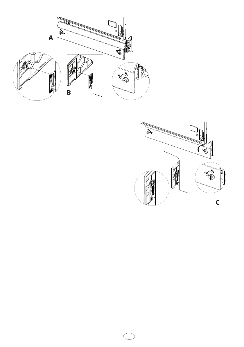
7.3 ADJUSTING THE MOVABLE TOE KICK
Now that you have successfully nstalled the dshwasher, you
need to attach the toe kck to the dshwasher. The two pece
toe kck can be adjusted to the heght and depth needed for
your ktchen. Be sure to use the slotted toe kck n the front
and the other behnd t. They slde nto each other.
Place parts K and L to the channel shown n Fgure A for both
sdes as shown n Fgure B. Then fx them n the drecton
shown wth the arrow n Fgure C and Fgure B.
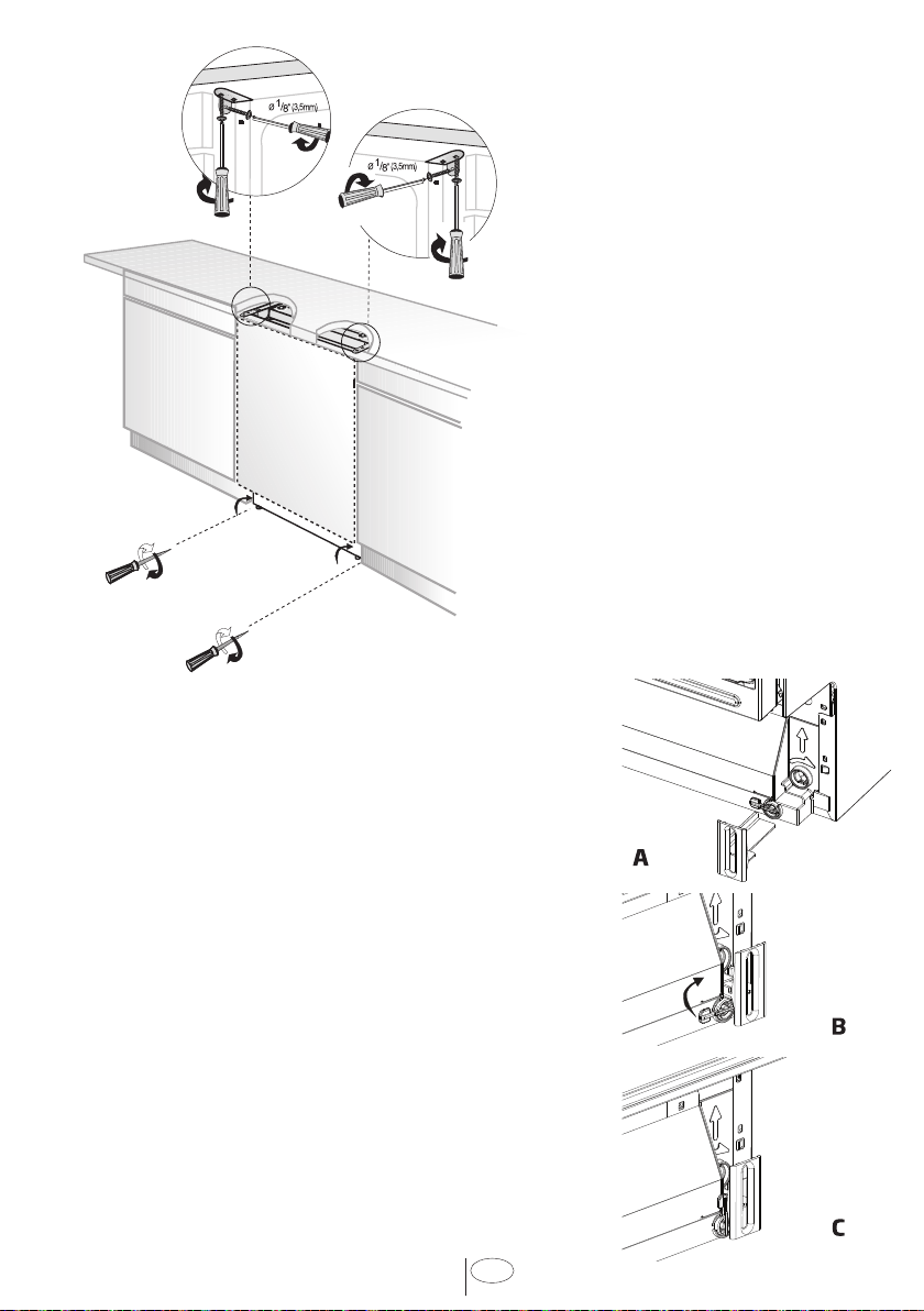
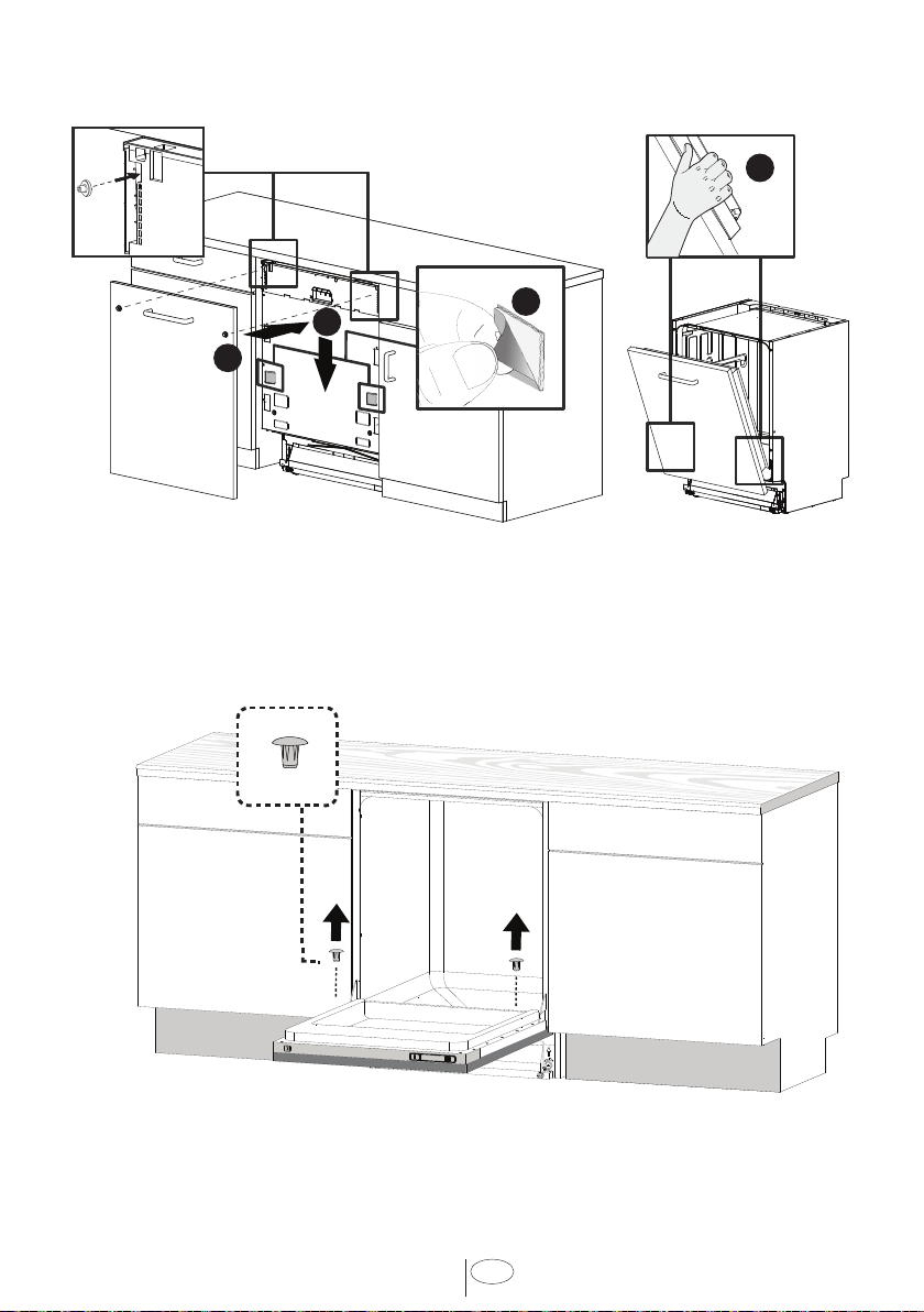
7.2 READJUSTING FOOT
LEVELS
Now that the dshwasher s n the
cabnet you must readjust the feet to
brng the dshwasher up to the requred
heght and attach t underneath the
countertop.
1. Readjust the front foot levels wth
adjustng wrench to balance the
dshwasher and rase t up under the
countertop, make sure the unt s level.
2. Readjust the rear foot levels wth a
screwdrver to balance the dshwasher
and rase t to the requred heght usng
the brackets suppled.
3. Attach the dshwasher underneath
the countertop wth the four screws
suppled (Ø 1/8” x 1/8” - Ø 3.5mm
x 14mm). Make sure you do not go
through the top of the countertop or
damage grante.
TALL TUB MODELS ONLY
19
USA
Open the fxng part on the Toe Kck(p). (A)
Place t on the slots, whch are on the brackets
fxed before, and adjust the heght (max. 40
mm). (B)
Close the fxng part on the Toe Kck. (C)
TALL TUB MODELS ONLY
20
USA
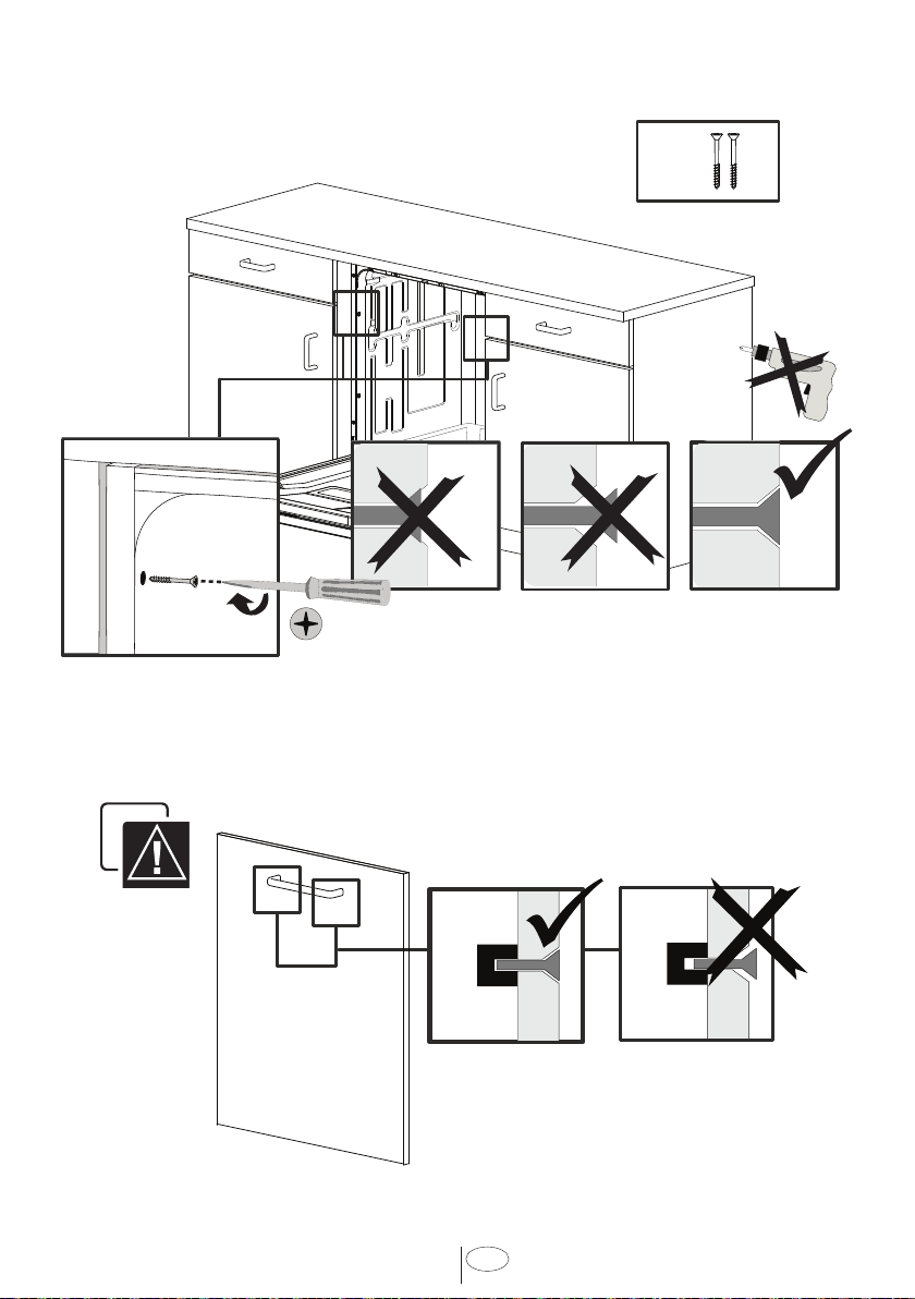
7.4 FIXING THE CABINET TO THE COUNTER
(y)
STANDARD TUB MODELS
21
USA
TALL TUB MODELS
y
22
USA
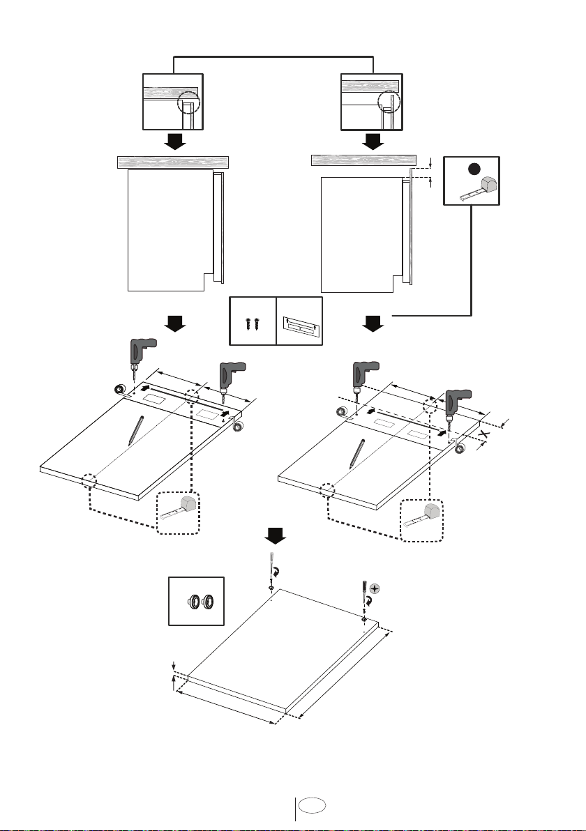
7.5 PREPARING THE TIMBER DOOR
X =
?
X
=
=
Mid. Point
=
=
Mid. Point
Heght (h) : Heght of the wooden door 30” (760mm) Tall Tub Models Only
Heght (h) : Heght of the wooden door 28” (720mm) Standard Tub Models Only
Wdth (w) : 23 ¼” to 23 ½” (592mm - 595mm)
Thckness (t) : ¾ “ (19mm)
Weght (max) : 9 Kg / 19 lbs
Weght (max)
9 Kg / 19 lbs
o) s)
n)
t)
23
USA
1
2
7.6 PREPARING THE PRODUCT DOOR
(t)
24
USA
1
2
3
4
1
2
3
4
5
6
1
2
3
4
5
6
7.9 INSTALLING THE TIMBER DOOR
7.10 FIXING THE TIMBER DOOR
25
USA
7.11 FIXING THE TIMBER DOOR
7.12 ADJUSTING THE KICK PLATE
• Check whether the
bottom of the door
hts the toe kck of the
ktchen cabnet (
A
).
• If the door hts the toe
kck cut the necessary
secton out of the toe
kck (
B
).
• Apply slcon or sealant
to the cut edge of the
ktchen cabnet toe kck
or pant so t does not
absorb mosture.
1
2
3
4
5
1
2
3
4
5
Ø 4 x 43mm
(yy)
26
USA
min 300
~ 1500
~ 1800
~ 2000
min 500
max 1000
max 1000
1
2
3
4
c
1
2
1
2
1
2
4
3
min
300
min
120
max 1000
min 500
7.13 CONNECTION
27
USA
8. INSTALLER CHECKLIST
Your nstaller must have completed and
checked the followng:
• The dishwasher is square and level.
• The dishwasher is fastened securely
to the cabinetry.
• The dishwasher door opens and closes
freely. The dishwasher door must
close without hitting any cabinetry or
counter top.
• The inlet water supply is turned on
and checked for leaks.
• The drain hose has been connected
and checked for leaks. There must be
no kinks or obstructions in the drain
hose.
• The drain hose must be installed with
a 28" (710mm) high drain loop for drain
hook-ups without any air removed.
• If the dishwasher drain is hooked up to
a garbage disposal, the drain hopper
plug must be removed.
• The spray arms are free and rotate
freely.
• The rinse cycle has been run.
• The water level will be below the
filter screen after the end of the wash
program. It is normal to find some
water in the drain filter area.
9. SELF HELP HINTS:
The screen does not come on:
• Check to make sure the breaker to the
dishwasher is in the on position.
• Check to make sure that the Supply
cord is plugged.
No Water is coming into the
dishwasher:
• Check to make sure the hot water
shut-off is in the ON position.
Water does not drain:
• Make sure drain hose is not kinked or
comes out of air gap next to the sink.
• Remove drain hose from disposal
making sure plug is removed.
NOTICE :
• If your dishwasher is not operating
properly after following these steps:
Contact your dealer to schedule an
authorized service agent to inspect
your new dishwasher for any function
related failure.
• The manufacturer warranty does
not cover installation, conversion or
customer education service visits.
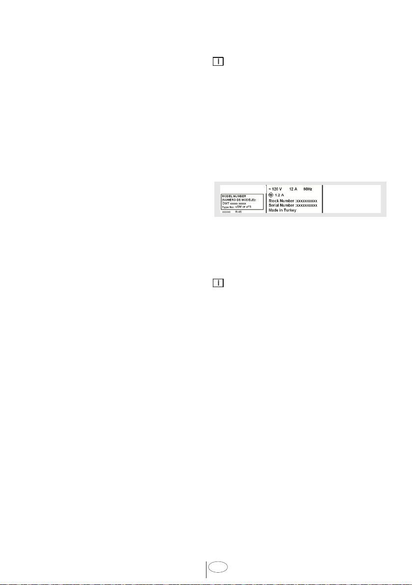
You wll fnd the model and seral number
nformaton on the label located on the
rght-hand sde of the nner door of your
dshwasher, as shown above.
NOTICE :
Please make a copy of your nvoce and
keep t wth ths manual and regster your
dshwasher on-lne.