
1
Installation Guide
Rack Rail Depth
Adapter Kit
Models: SRRAILDPTH1U, SRRAILDPTH2U
1111 W. 35th Street, Chicago, IL 60609 USA • tripplite.com/support
Copyright © 2021 Tripp Lite. All rights reserved.
WARRANTY REGISTRATION
Register your product today and be
automatically entered to win an ISOBAR
®
surge protector in our monthly drawing!
tripplite.com/warranty
Español 3 • Français 5 • Русский 7
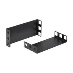
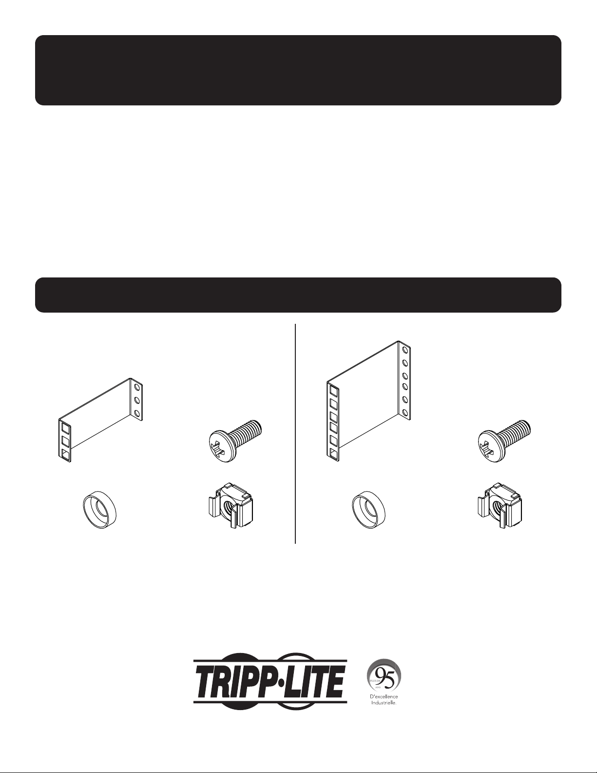
Parts List
Adapter Brackets (x2)
M6 Screws (x8) Adapter Brackets (x2)
M6 Screws (x16)
SRRAILDPTH1U SRRAILDPTH2U
M6 Cup Washers (x8) M6 Cage Nuts (x8) M6 Cup Washers (x16) M6 Cage Nuts (x16)
2
1111 W. 35th Street, Chicago, IL 60609 USA • tripplite.com/support
21-04-297 93-3E42_RevA
Installation
Tripp Lite has a policy of continuous improvement. Specifications are subject to change without notice.
Photos and illustrations may differ slightly from actual products.
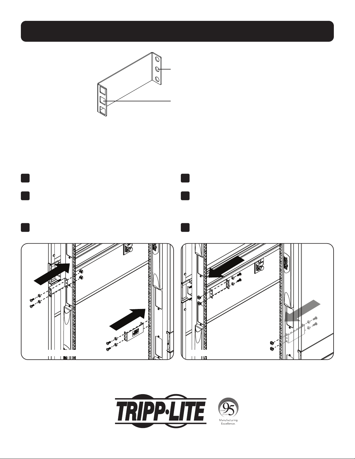
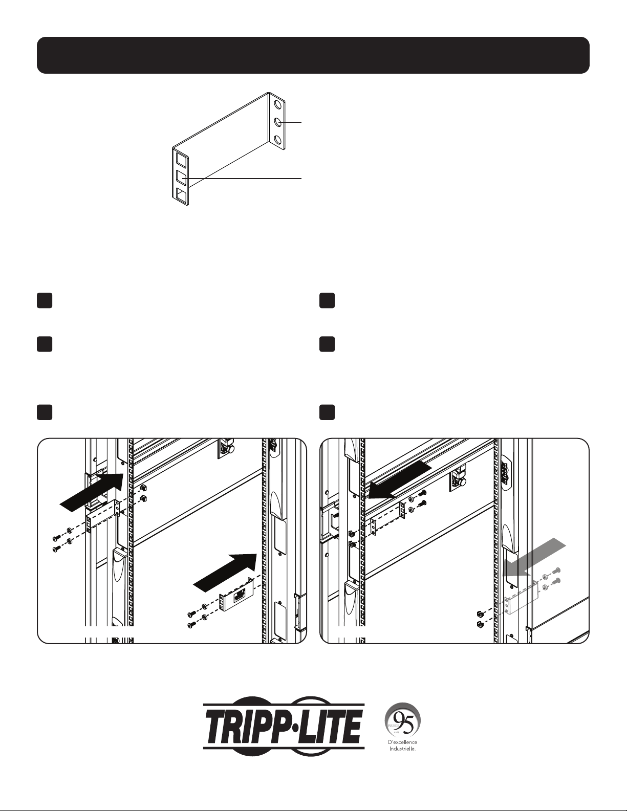
Rack-Mounting Holes
Equipment-Mounting Holes
To INCREASE the Depth of the
Rack
Use for rack-mounting LONGER
components.
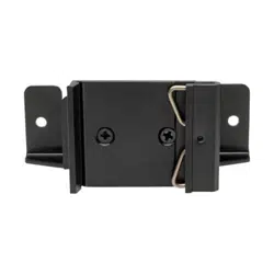
1
Position the brackets so the rack-mounting holes are
on the outside of the rack’s front vertical rails.
2
For 1U brackets, use two of the supplied M6 screws,
washers and cage nuts per bracket to secure the top
and bottom rack-mounting holes to the rails. For 2U
brackets, secure the top, bottom and two center holes.
3
Secureyourequipment’smountingangestothe
brackets’ equipment-mounting holes.
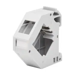
To DECREASE the Depth of
the Rack
Use for rack-mounting SHORTER
components.
1
Position the brackets so the rack-mounting holes are
on the inside of the rack’s front vertical rails.
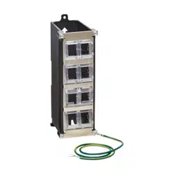
2
For 1U brackets, use two of the supplied M6 screws,
washers and cage nuts per bracket to secure the top
and bottom rack-mounting holes to the rails. For 2U
brackets, secure the top, bottom and two center holes.
3
Secureyourequipment’smountingangestothe
brackets’ equipment-mounting holes.
SRRAILDPTH1U shown.
SRRAILDPTH1U shown. SRRAILDPTH1U shown.

3
Guía de Instalación
Juego de Adaptador de
Profundidad de Riel para Rack
Modelos: SRRAILDPTH1U, SRRAILDPTH2U
1111 W. 35th Street, Chicago, IL 60609, EE. UU. • tripplite.com/support
Copyright © 2021 Tripp Lite. Todos los derechos reservados.
English 1 • Français 5 • Русский 7
Lista de Partes
Soportes de Adaptador (x2)
Tornillos M6 (x8) Soportes de Adaptador (x2)
Tornillos M6 (x16)
SRRAILDPTH1U SRRAILDPTH2U
Arandelas de copa M6 (x8) Tuercas de fijación M6 (x8) Arandelas de Copa M6
(x16)
Tuercas de fijación M6
(x16)
4
1111 W. 35th Street, Chicago, IL 60609, EE. UU. • tripplite.com/support
21-04-297 93-3E42_RevA
Instalación
Tripp Lite tiene una política de mejora continua. Las especificaciones están sujetas a cambio sin previo aviso.
Las fotografías e ilustraciones pueden diferir ligeramente de los productos reales.
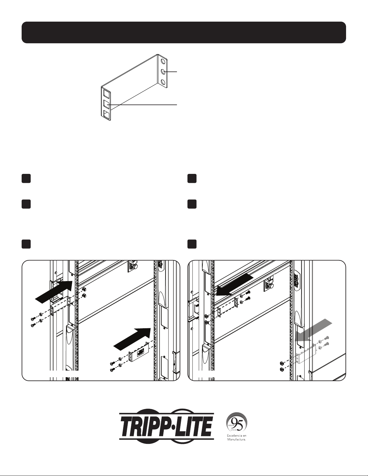
Orificios para Instalación en Rack
Orificios para Instalación del Equipo
Para AUMENTAR la
Profundidad del Rack
Use para componentes MÁS GRANDES
para instalación en rack.
1
Coloquelossoportesdemodoquelosoriciospara
instalación en rack estén en la parte exterior de los rieles
verticales frontales del rack.
2
Para soportes de 1U, use dos de los tornillos M6,
arandelasytuercasdejaciónsuministradosporcada
soporteparajarlosoriciossuperioreinferiorpara
instalación en rack a los rieles. Para soportes de 2U,
asegurelosoriciossuperior,inferiorylosdoscentrales.
3
Asegure las bridas de instalación de su equipo a los
oriciosdeinstalacióndelequipodelossoportes.
Para REDUCIR la Profundidad
del Rack
Use para componentes MÁS PEQUEÑOS
para instalación en rack.
1
Coloquelossoportesdemodoquelosoriciospara
instalación en rack estén en el interior de los rieles
verticales frontales del rack.
2
Para soportes de 1U, use dos de los tornillos M6,
arandelasytuercasdejaciónsuministradosporcada
soporteparajarlosoriciossuperioreinferiorpara
instalación en rack a los rieles. Para soportes de 2U,
asegurelosoriciossuperior,inferiorylosdoscentrales.
3
Asegure las bridas de instalación de su equipo a los
oriciosdeinstalacióndelequipodelossoportes.
Se muestra SRRAILDPTH1U.
Se muestra SRRAILDPTH1U.
Se muestra SRRAILDPTH1U.
5
Guide d'installation
Trousse pour adaptateur de la
profondeur des rails d'un bâti
Modèles : SRRAILDPTH1U, SRRAILDPTH2U
1111 W. 35th Street, Chicago, IL 60609 USA tripplite.com/support
Droits d'auteur © 2021 Tripp Lite. Tous droits réservés.
English 1 • Español 3 • Русский 7
Liste des pièces
Supports d'adaptateur (x2)
Vis M6 (x8) Supports d'adaptateur (x2)
Vis M6 (x16)
SRRAILDPTH1U SRRAILDPTH2U
Rondelles à collerette M6
(x8)
Écrous à cage M6 (x8) Rondelles à collerette M6
(x16)
Écrous à cage M6 (x16)
6
1111 W. 35th Street, Chicago, IL 60609 USA tripplite.com/support
21-04-297 93-3E42_RevA
Installation
La politique de Tripp Lite en est une d'amélioration continue. Les caractéristiques techniques sont modifiables sans préavis.
Les produits réels peuvent différer légèrement des photos et des illustrations.
Trous pour le montage en bâti
Trous pour le montage de
l'équipement
Pour AUGMENTER la
profondeur du bâti
À utiliser pour le montage en bâti de
composants plus LONGS.
1
Placer les supports pour que les trous pour le montage
en bâti se trouvent à l'extérieur des rails verticaux avant
du bâti.
2
Pour les supports 1U, utiliser deux des vis M6 fournies,
des rondelles et des écrous à cage fournis par support
pour retenir les trous supérieurs et inférieurs pour le
montage en bâti aux rails. Pour les supports 2U, xer les
trous supérieurs, inférieurs et les deux trous du centre.
3
Fixer les brides de montage de l'équipement aux trous de
montage de l'équipement des supports.
Pour RÉDUIRE la profondeur
du bâti
À utiliser pour le montage en bâti de
composants plus COURTS.
1
Placer les supports pour que les trous pour le montage
en bâti se trouvent à l'intérieur des rails verticaux avant
du bâti.
2
Pour les supports 1U, utiliser deux des vis M6 fournies,
des rondelles et des écrous à cage fournis par support
pour retenir les trous supérieurs et inférieurs pour le
montage en bâti aux rails. Pour les supports 2U, xer les
trous supérieurs, inférieurs et les deux trous du centre.
3
Fixer les brides de montage de l'équipement aux trous de
montage de l'équipement des supports.
SRRAILDPTH1U illustré.
SRRAILDPTH1U illustré. SRRAILDPTH1U illustré.

7
Руководство по установке
Комплект приспособлений для
регулировки глубины стоечных шин
Модели: SRRAILDPTH1U, SRRAILDPTH2U
1111 W. 35th Street, Chicago, IL 60609 USA • tripplite.com/support
Охраняется авторским правом © 2021 Tripp Lite. Перепечатка запрещается.
English 1 • Español 3 • Français 5
Комплектация
Переходные кронштейны (2 шт.)
Винты M6 (8 шт.) Переходные кронштейны (2 шт.)
Винты M6 (16 шт.)
SRRAILDPTH1U SRRAILDPTH2U
Чашеобразные шайбы M6 (8 шт.) Закладные гайки M6 (8 шт.) Чашеобразные шайбы M6 (16 шт.) Закладные гайки M6 (16 шт.)
8
1111 W. 35th Street, Chicago, IL 60609 USA • tripplite.com/support
21-04-297 93-3E42_RevA
Установка
Компания Tripp Lite постоянно совершенствует свою продукцию. B связи с этим возможно изменение технических характеристик без предварительного уведомления.
Внешний вид реальных изделий может несколько отличаться от представленного на фотографиях и иллюстрациях.
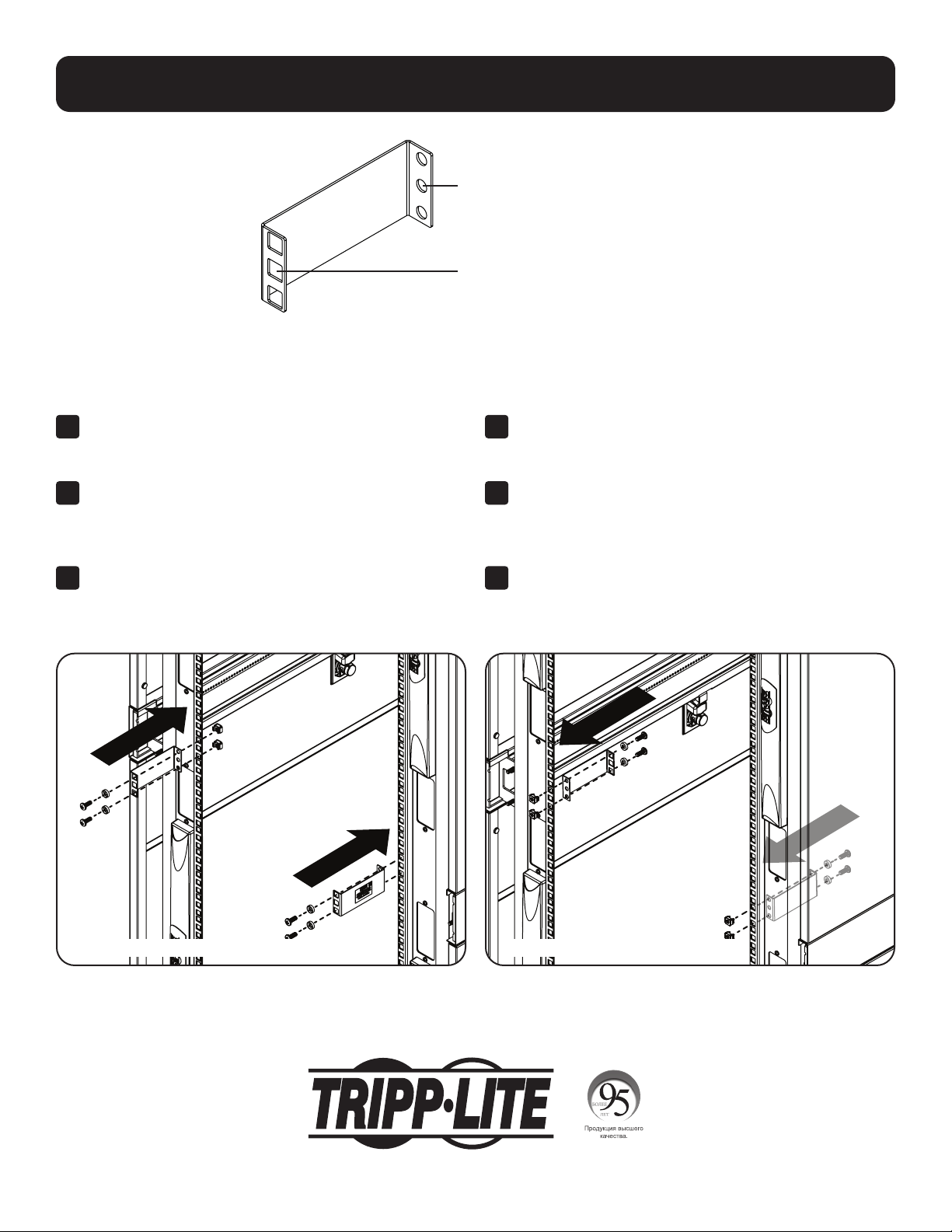
Отверстия для стоечного монтажа
Отверстия для монтажа оборудования
Для УВЕЛИЧЕНИЯ глубины стойки
Для монтажа в стойку ДЛИННОМЕРНЫХ компонентов.
1
Расположите кронштейны таким образом, чтобы отверстия для стоечного
монтажа находились снаружи по отношению к передним вертикальным
шинам стойки.
2
Для кронштейнов размером 1U используйте поставляемые в комплекте
винты M6, шайбы и закладные гайки для фиксации верхних и нижних
отверстий для стоечного монтажа на шинах. Для кронштейнов размером
2U зафиксируйте верхнее, нижнее и два центральных отверстия.
3
Прикрепите монтажные фланцы своего оборудования к кронштейнам,
используя отверстия для монтажа оборудования.
Для УМЕНЬШЕНИЯ глубины стойки
Для монтажа в стойку КОРОТКОМЕРНЫХ компонентов.
1
Расположите кронштейны таким образом, чтобы отверстия для стоечного
монтажа находились внутри по отношению к передним вертикальным
шинам стойки.
2
Для кронштейнов размером 1U используйте поставляемые в комплекте
винты M6, шайбы и закладные гайки для фиксации верхних и нижних
отверстий для стоечного монтажа на шинах. Для кронштейнов размером
2U зафиксируйте верхнее, нижнее и два центральных отверстия.
3
Прикрепите монтажные фланцы своего оборудования к кронштейнам,
используя отверстия для монтажа оборудования.
На иллюстрации показана модель
SRRAILDPTH1U.
На иллюстрации показана модель SRRAILDPTH1U. На иллюстрации показана модель SRRAILDPTH1U.