Loading ...
Loading ...
Loading ...
Cupboard / Hood / Side Clearances
Nominal width of the hob
Wall Cabinet
400mm
90mm
90mm
400mm
min
600mm
Benchtop Benchtop
View from front
Benchtop Benchtop
70mm
• If your appliance has a side opening door, we recommend a side clearance of 70mm to allow the
oven door to fully open, if placed up to a wall or cabinetry.
• The cooker must have a side clearance above hob level of 90mm up to a height of 400mm.
DIMENSIONS AND CLEARANCES - OPTION 2
View from above, with the
appliance located in a corner
*If above installation method is used then
rangecooker must protrude in front of
cabinetry so rangecooker doors do not
infringe onto cabinetry. Refer Fig.2
Rangecooker Width 896/1096mm
Benchtop Width 900/1100mm (Minimum)
Wall Cabinet
Maximum
Cabinetry
Depth
570mm
Benchtop
Depth
600mm
No shelf or overhang of combustible material should
be closer than 600mm above the hob.
For the required clearance between rangehood and the
hob refer to the rangehood user manual.
Front of rangecooker doors need to protrude
past cabintery doors by at least 30mm
* Min 2mm clearance required
between cabinets and
rangecooker
* Min 2mm clearance required
between cabinets and
rangecooker
FIG.2
FIG.1
CONNECT TO THE ELECTRICITY SUPPLY - TERMINAL BLOCK
WARNING: This appliance must be earthed.
7KLVDSSOLDQFHPXVWEH¿WWHGWRDVZLWFKSURYLGLQJDOOSROHGLVFRQQHFWLRQZLWKDPLQLPXPFRQWDFW
separation of 3mm.
Access to the mains terminal is gained by removing the terminal block cover at the rear of the
appliance.
&RQQHFWLRQVKRXOGEHPDGHZLWKDVXLWDEOHÀH[LEOHFDEOHZLWKDPLQLPXPWHPSHUDWXUHUDWLQJRI
70°C.
First strip the wires then push the cable through the cable clamp.
Connect the cable to the terminal block and tighten the cable clamp screws - see diagram.
5H¿WWKHWHUPLQDOER[FRYHU
6XႈFLHQWFDEOHVKRXOGEHXVHGWRDOORZWKHFRRNHUWREHSXOOHGRXWEXWPXVWKDQJFOHDURIWKHÀRRU
so it does not become twisted or trapped when the cooker is pushed back.
The terminal block screws and clamps can be damaged by excessive tightening and untightening. DO
NOT USE POWER TOOLS!
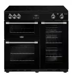
Single Phase Connection (240V ~ 50Hz)
4
5
2
3
6
1
N
L
Shorting
Links
Shorting
Link
Connect cable to terminal block:
L to terminal 2.
N to terminal 5.
Earth to terminal.
Ensure shorting links are fitted between
terminals 1-2, 2-3, 4-5 and 5-6.
Ensure all screws are fully tightened.
Cable
Clamp
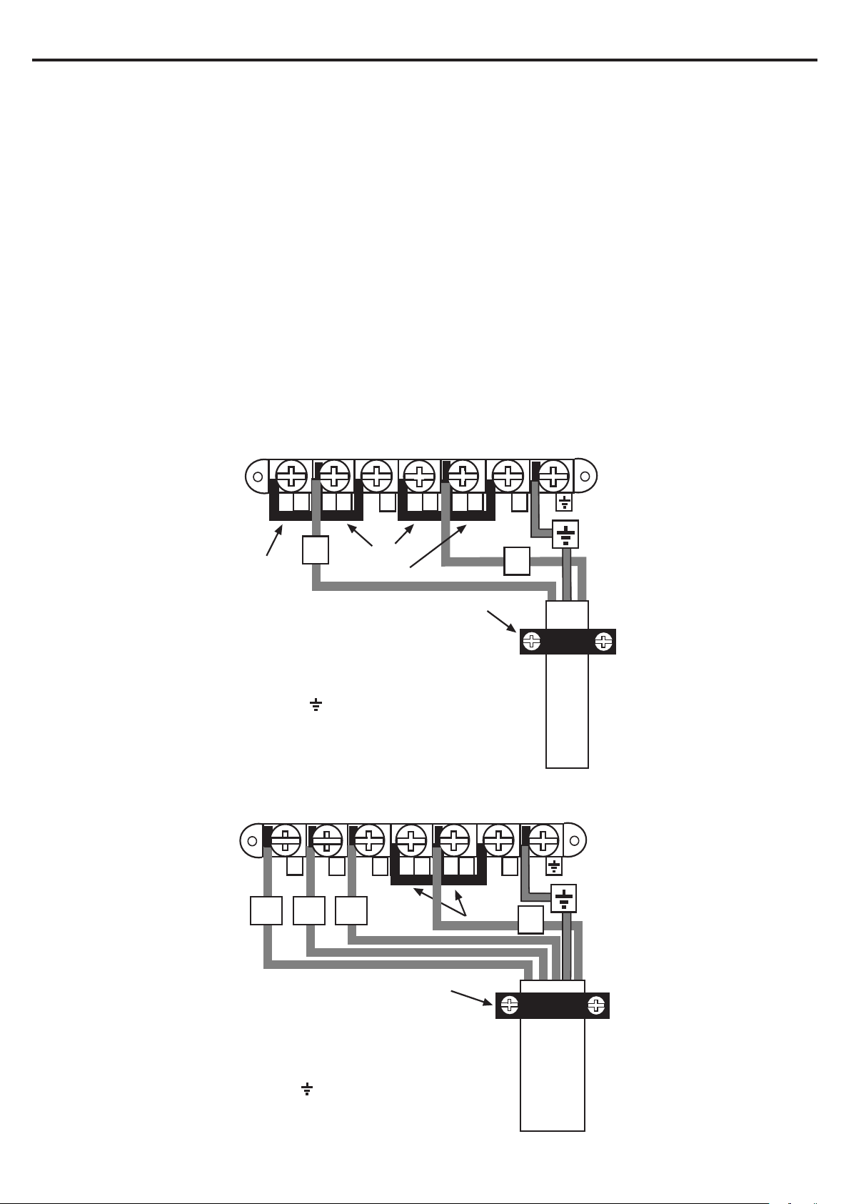
Three Phase Connection (240/415V 3N ~ 50Hz)
4
5
2
3
6
1
N
Shorting
Links
Connect cable to terminal block:
Remove shorting links 1-2 and 2-3
L1, L2 and L3 to terminals 1, 2 and 3.
N to terminal 5.
Earth to terminal.
Ensure shorting links are fitted between
terminals 4-5 and 5-6.
Ensure all screws are fully tightened.
Cable
Clamp
L1
L2
L3
Loading ...
Loading ...
Loading ...