

English
Welcome!
We hope you share our dream for the television industry to become a truly creative
industry by allowing anyone to have access to the highest quality video.
Video monitoring is needed everywhere in a facility. SmartView 4K has a native 4K LCD
so you can monitor Ultra HD video in full resolution, plus a sleek 6RU housing with a
control panel that lets you quickly change settings. SmartView HD provides an amazing
17” LCD in a 6RU rack housing less than an inch thick. SmartView Duo provides two
completely independent and beautiful 8 inch LCDs in a 3RU rack housing less than an
inch thick. SmartScope Duo 4K features two independent 8” LCDs with waveform scope
functionality, allowing you to monitor your video levels on the fly. All SmartView monitors
support SD, HD and 2K video via 3G-SDI. SmartScope Duo 4K and SmartView 4K also
support Ultra HD 4K via 6G-SDI and 12G-SDI respectively!
Video monitoring is designed to work straight out of the box and our Blackmagic
SmartView setup software provides the user with an easy and intuitive configuration tool.
This instruction manual should contain all the information you’ll need on installing your
SmartView or SmartScope, although it’s always a good idea to ask a technical assistant
for help if you are not sure what IP addresses are, or if you don’t know much about
computer networks. SmartView and SmartScope are easy to install, however, there are a
few slightly technical preferences you may need to set after you install it.
We think it should take you approximately 5 minutes to complete Installation. Please
check our website at www.blackmagicdesign.com and click the support page to
download the latest updates to this manual and SmartView software. Lastly, please
register your unit when downloading software updates so we can keep you updated
when new software is released. We are constantly working on new features and
improvements, so we would love to hear from you!
Grant Petty
CEO Blackmagic Design

Contents
SmartView & SmartScope
Getting Started 5
Introducing SmartView and SmartScope 5
Plugging in Video Sources 6
Plugging in your Computer 6
Installing Blackmagic SmartView Setup 7
Using Blackmagic SmartView Setup 8
Updating the Software 8
Adjusting Monitor Settings 8
Using SmartView 4K 11
Introducing Blackmagic SmartView 4K 11
Control Panel Buttons 12
Loading 3D LUTs using Blackmagic SmartView Setup 14
Using SmartScope Duo 4K 15
What is Blackmagic SmartScope? 15
Video Monitoring Display 15
Waveform Display 16
Vectorscope Display 17
Parade Display 19
Histogram Display 20
Audio Metering Display 21
Connecting to a Network 22
Direct Ethernet 23
Ethernet Network Switch 23
Adjusting Network Settings 25
Network Settings 25
Adding a Blackmagic Monitor 26
Using Tally 27
Tally Port Pin Connections 27
Optimizing the Viewing Angle 28
Developer Information 30
Blackmagic 2K Format – Overview 30
Blackmagic 2K Format – Vertical Timing Reference 31
Blackmagic 2K Format – Data Stream Format 32
Blackmagic SmartView Ethernet Protocol v1.3 33
Help 37
Regulatory Notices andSafetyInformation 38
Warranty 39
Getting Started
Introducing SmartView and SmartScope
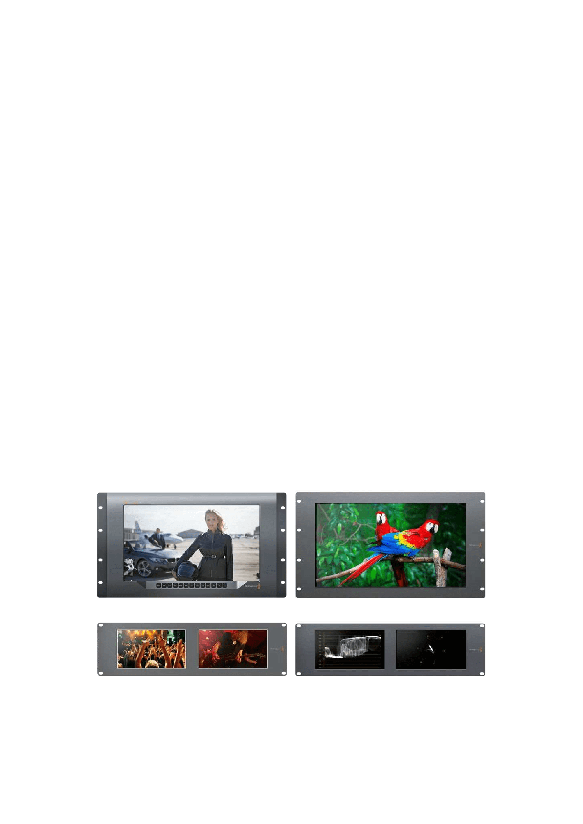
SmartView monitors are perfect for any facility which requires rack-based monitoring. To simply
get up and running, the only thing you need to do is plug in power and connect an SDI source!
SmartView 4K has a 15.6” 4K LCD so you can monitor SD, HD, or Ultra HD video in its native
3840x2160 pixel resolution. The front control panel buttons mean you can easily select inputs,
adjust the screen brightness, check for noise in the blue channel, view blanking information,
apply 3D LUTs and more.
SmartView HD has a 17” HD LCD which is perfect for confidence monitoring in full
resolution HD.
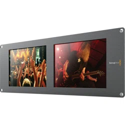
SmartView Duo has two monitors for simultaneous display of different video signals.
Forexample, one monitor can display a YUV 4:2:2 signal while the other receives RGB 4:4:4.
One monitor could be showing NTSC while the other shows PAL. There are many possible
combinations but it is all as simple as connecting a single SDI cable to each monitor!
SmartScope Duo 4K has all the same features as SmartView Duo plus can be used to display
waveform, vectorscope and other popular scopes for monitoring video and audio levels in real
time. Plus, you get full support for Ultra HD 4K!
All SDI input connections on SmartView and SmartScope monitors support auto detection of
SD, HD or 3G-SDI including 2K video. SmartView 4K also detects Ultra HD including formats
such as 2160p60 via 12G-SDI. SmartScope Duo 4K includes auto detection of Ultra HD 4K
video via 6G-SDI.
If you want to remotely adjust settings for multiple SmartView and SmartScope units from one
computer, you can connect them together via Ethernet. This means you won’t have to run
around to each unit with a computer and USB cable each time you want to adjust settings.
That’s all you need to get started! Please read on for more detailed instructions on connecting
SmartView and SmartScope, configuring monitor settings in Blackmagic SmartView setup, and
connecting to a network.
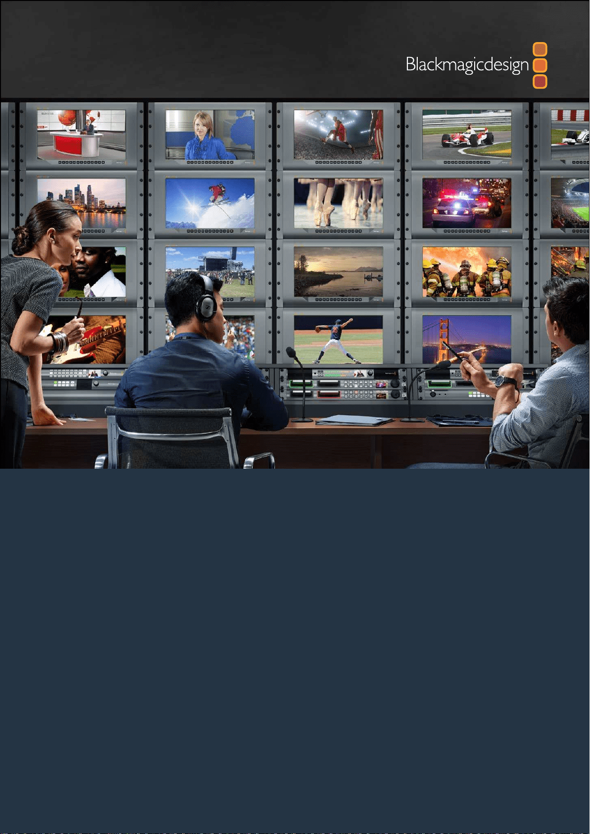
SmartView 4K SmartView HD
SmartView Duo SmartScope Duo 4K
5
Getting Started

Plugging in Video Sources
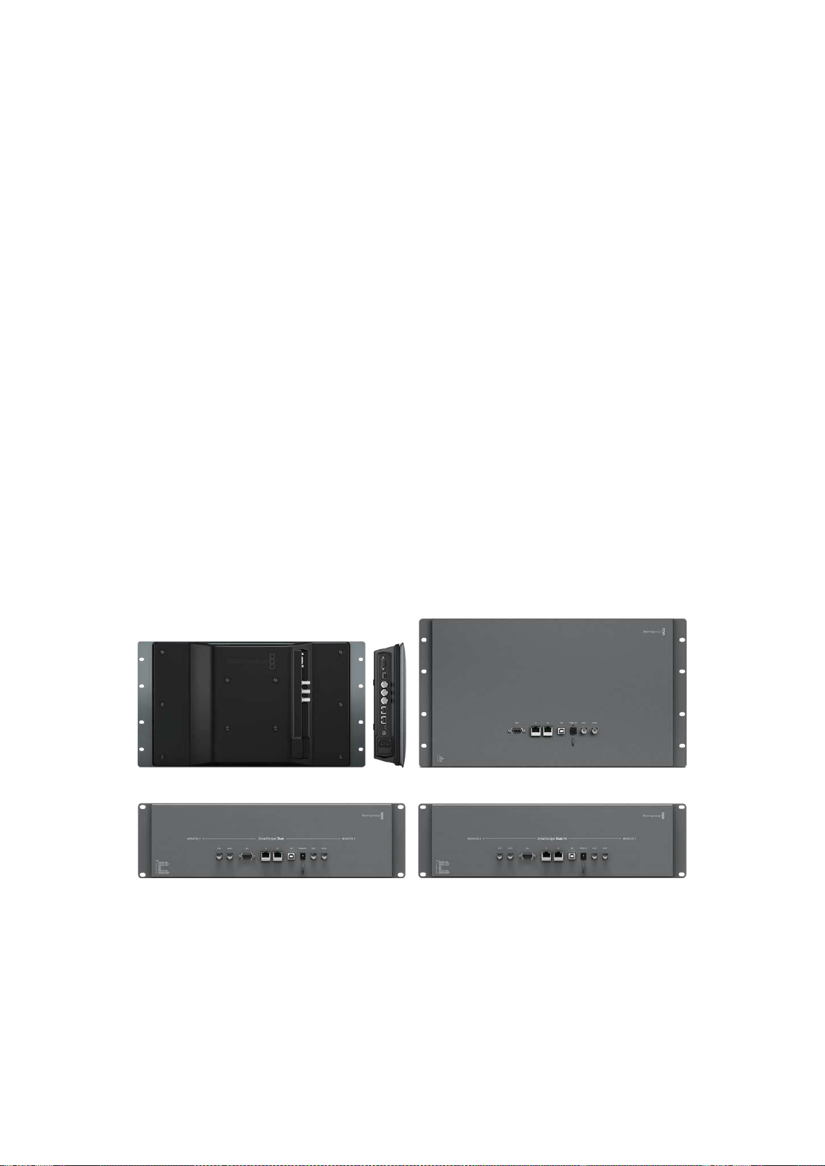
SmartView and SmartScope monitors feature regular BNC connectors to connect to SDI
equipment including switchers, cameras, capture cards, decks and disk recorders.
Getting a Picture
Displaying your video is easy! Simply power the unit and connect your video source to an SDI
input. Once powered and connected, your video should be immediately visible. SD, HD and
2K signals are automatically detected by the SDI input and loop through output connections.
SmartView 4K and SmartScope Duo 4K also detects Ultra HD 4K.
When no video is received by the unit, the backlight turns off, saving power until the next valid
signal is received.
Daisy chaining Monitors
Each SmartView and SmartScope monitor has its own independent SDI input as well as a loop
through output so you can chain multiple monitors together to display the same input signal:
1 Power on unit 1. Connect a video source to an SDI input. The video should
immediately be visible.
2 Power on unit 2. Connect an SDI cable from a loop output of unit 1 to an
SDI input on unit 2.
There is no limit to the amount of units you can chain.
If you are waveform monitoring using SmartScope Duo 4K, you’ll probably want to loop the
Monitor 1 output to Monitor 2 so both displays use the same input signal.
Now you have video displayed, you can adjust monitor settings, or select scopes on
SmartScope Duo 4K using the Blackmagic SmartView setup software, which you can also use
to load 3D LUTs on Blackmagic SmartView 4K.
SmartView 4K SmartView HD
SmartView Duo SmartScope Duo 4K
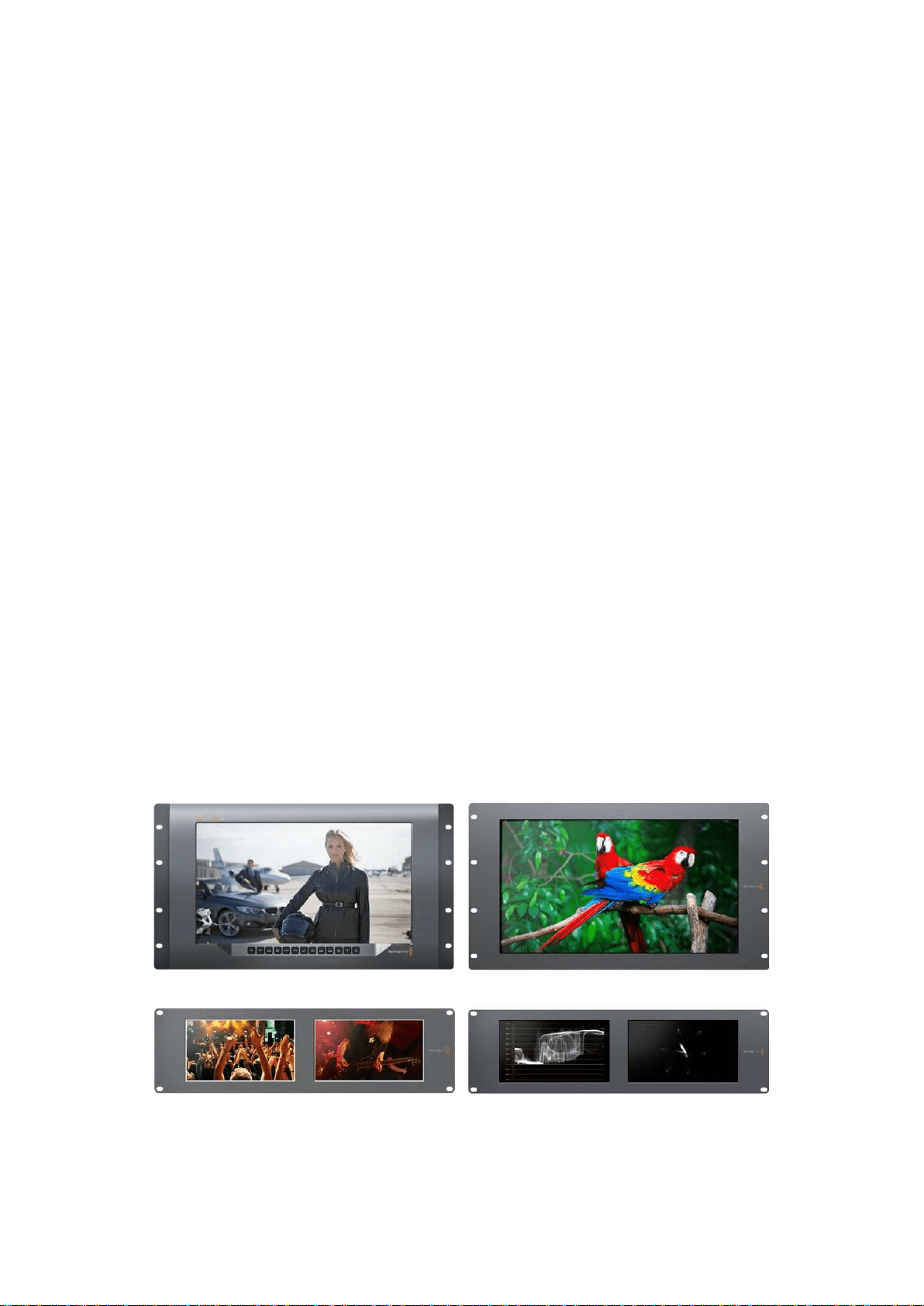
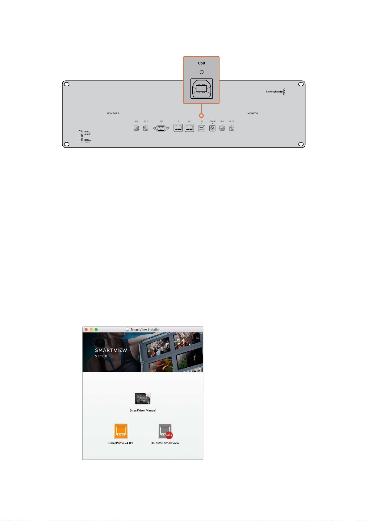
Plugging in your Computer
Configure SmartView or SmartScope monitor settings by connecting to your computer via USB
and installing Blackmagic SmartView setup.
The USB connection can also be used for applying internal software updates downloaded from
the Blackmagic Design website. Software updates can provide new features, compatibility with
new hardware and support for new formats. Blackmagic SmartView setup software runs on both
macOS and Windows computers.
6Getting Started
Installing Blackmagic SmartView Setup
Blackmagic SmartView setup runs on the latest Sierra and High Sierra versions of macOS, and
64-bit versions of Windows 8.1 and 10 with the latest service packs installed. Blackmagic
SmartView setup can be installed on multiple networked computers if desired.
The SD card supplied with SmartView contains the software installer, but we recommend
visiting www.blackmagicdesign.com/support to ensure you have the latest version.
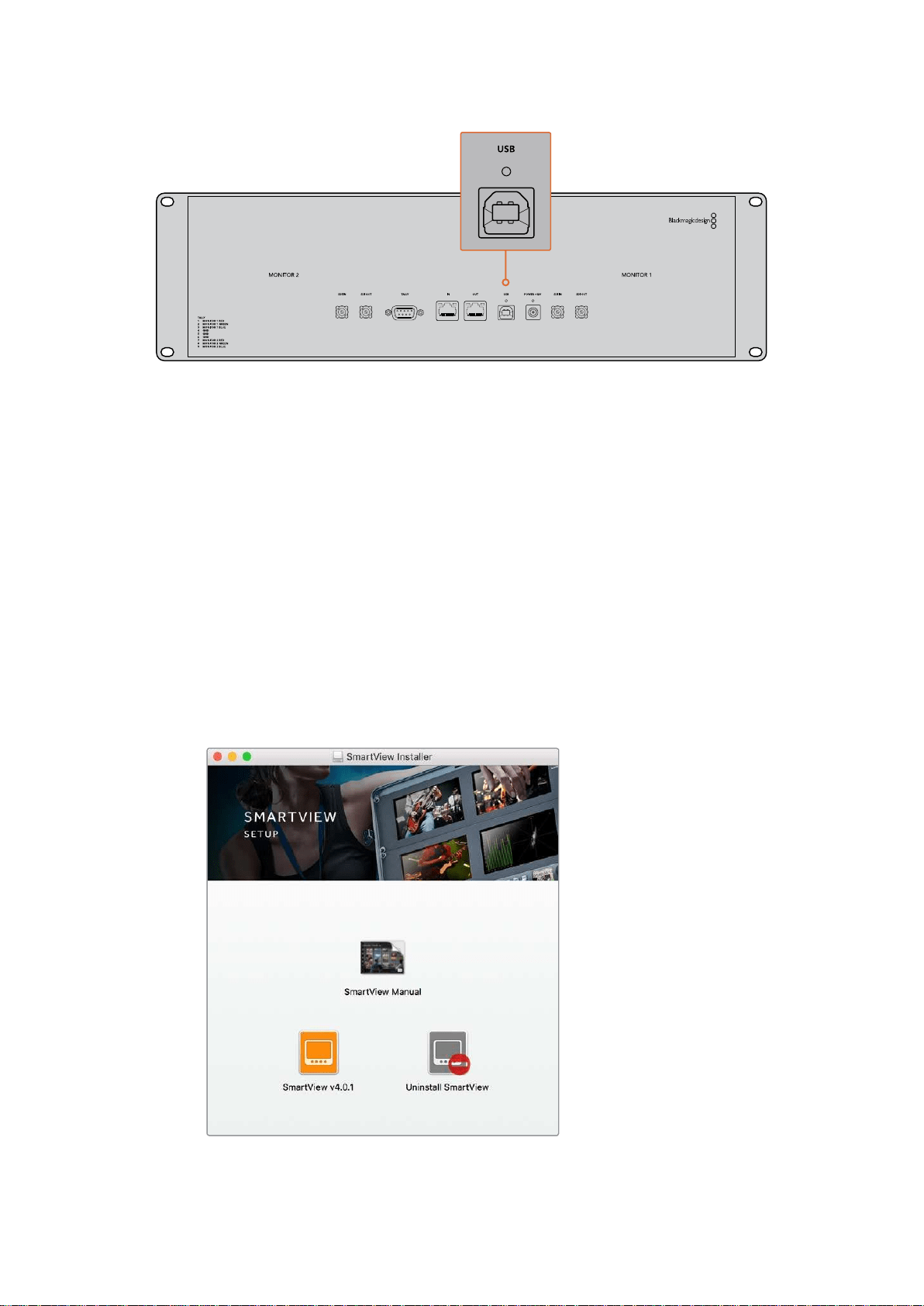
To install on macOS:
Open the supplied SD card, or downloaded disk image, and double click on the install
SmartView icon. A SmartView folder will be created in your applications folder, containing
SmartView setup, an uninstaller for removing previous versions when updating, and a
documents folder containing this manual plus other SmartView information.
To install on Windows:
On Windows, open the supplied SD card, or downloaded zip file, and double-click on the
SmartView installer. Follow the onscreen prompts to install the software.
To install on macOS, launch the SmartView.dmg file
on the suplied SD card, or from your downloads folder,
then double click on the install SmartView icon
7Getting Started
Using Blackmagic SmartView Setup
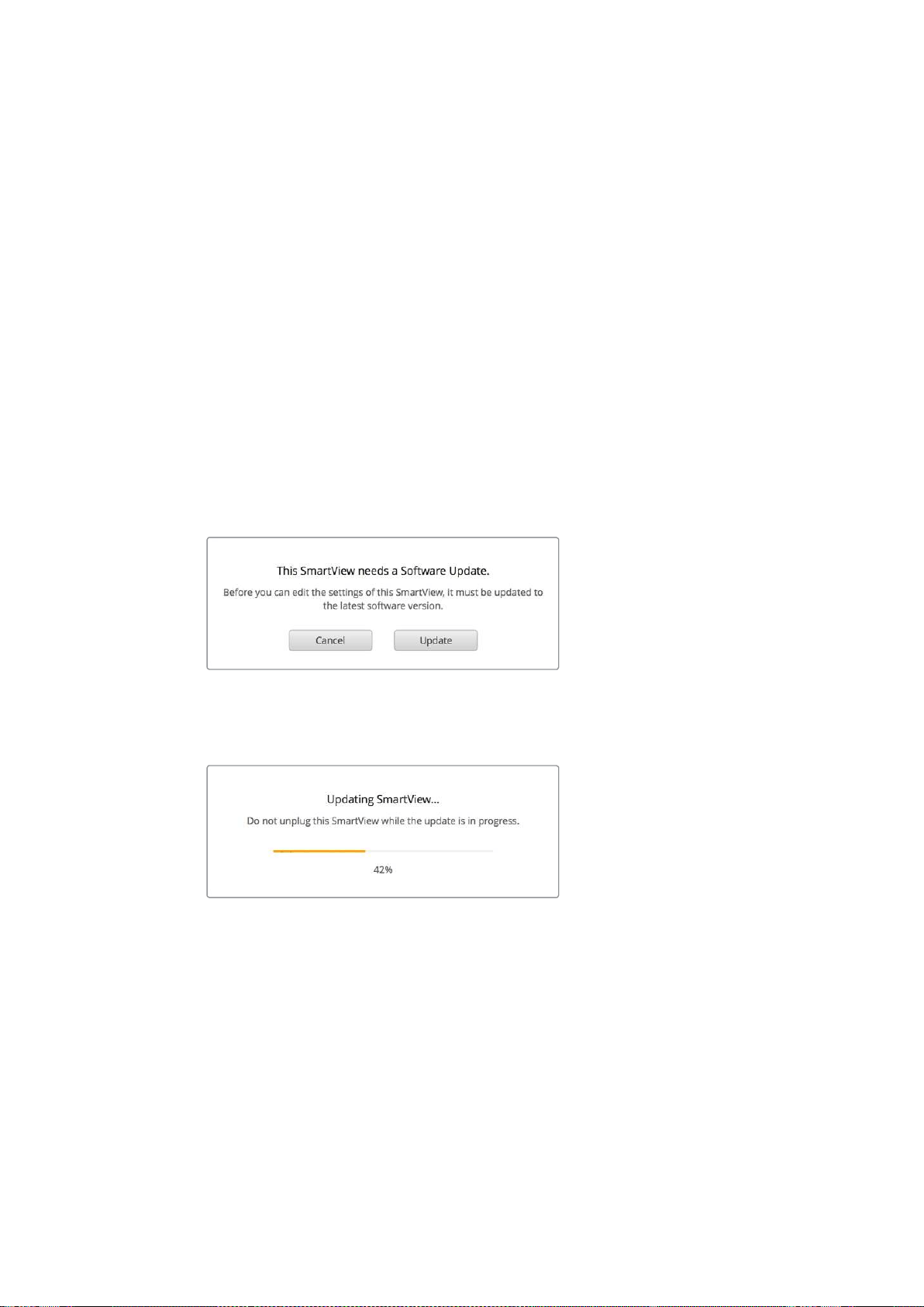
Updating the Software
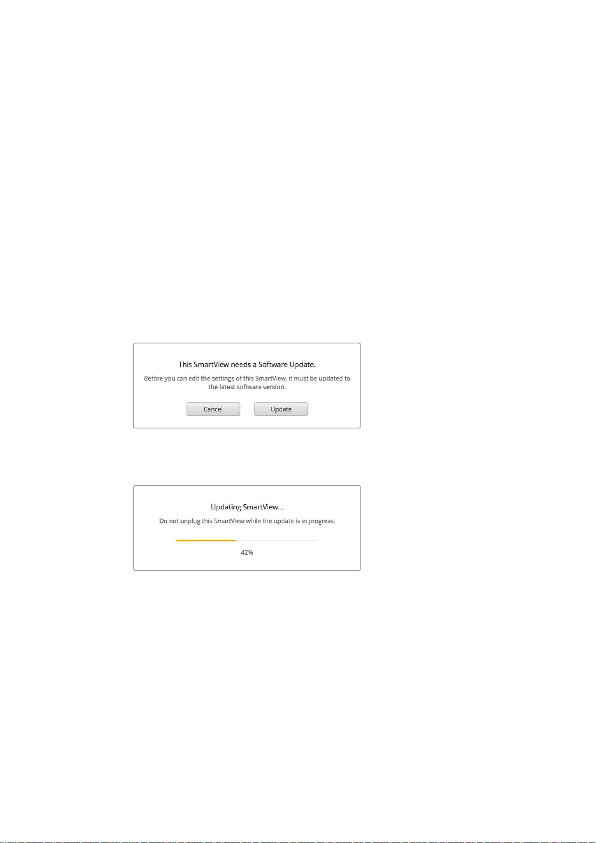
Once Blackmagic SmartView setup is installed and launched, click on the settings icon below
the name of your monitor. You may be prompted to update the internal software of your
SmartView or SmartScope. To do so:
1 Connect your SmartView or SmartScope to the computer via USB or
Ethernet and launch Blackmagic SmartView setup.
2 When prompted, simply click update. The update may take about 5 minutes
to complete.
3 The message: “This SmartView has been updated” should appear upon
completion of the update.
4 Click close.
If no internal software update is required, Blackmagic SmartView setup will open the settings
page for your monitor.
When launching SmartView setup and opening the settings
icon for your connected SmartView or SmartScope, this
message will appear if an internal software update is required
The update will take about 5 minutes to complete
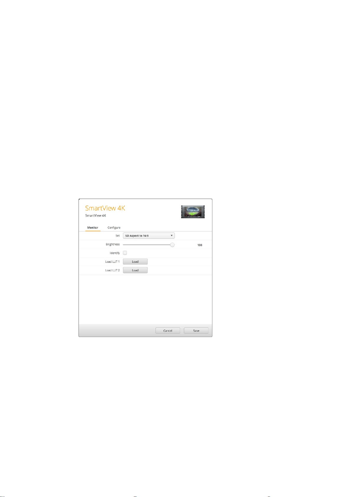
Adjusting Monitor Settings
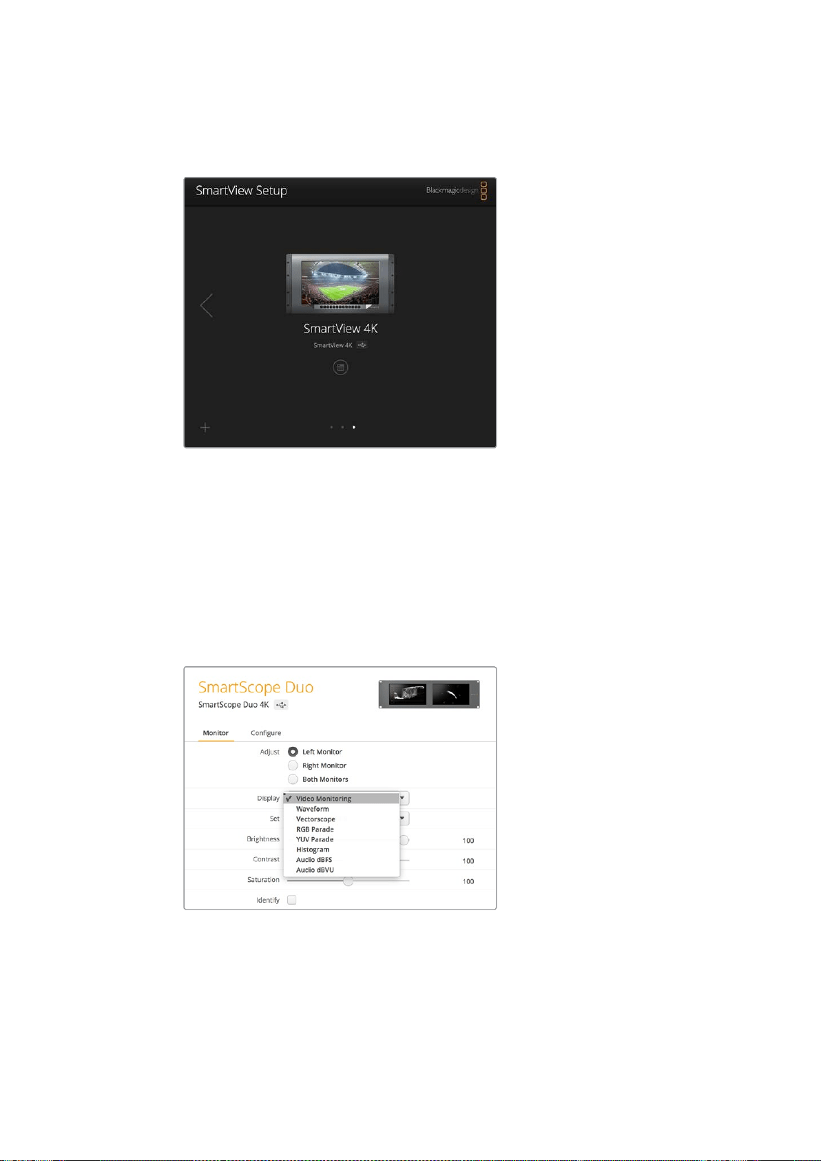
When launched, Blackmagic SmartView setup will immediately search for any SmartView or
SmartScope units connected via USB or Ethernet and display them in the SmartView setup
home page. If you have more than one Blackmagic monitor connected to your network, click on
the left and right arrow icons on each side of the home page to select the monitor you want to
adjust. If your Blackmagic monitor is connected via USB, a USB icon will appear next to the
monitor name.
8Using Blackmagic SmartView Setup

To adjust settings, select your monitor connected via Ethernet and USB, and click on the
settings icon below the monitor name. This will open the settings page for your selected
monitor. When you are happy with your settings, click the save button to save your settings and
return to the SmartView setup home page.
See the next section for information on settings that are available for Blackmagic monitors and
how to apply them. For information on how to configure network settings using Blackmagic
SmartView setup, turn to the section “adjusting network settings”.
Blackmagic SmartView setup automatically searches for any
SmartView and SmartScope units connected locally via USB
or over a network. When updating your monitor’s internal
software make sure your monitor is connected via USB or
Ethernet. A USB icon will appear next to your monitor’s name.
Monitor Settings
To adjust settings and displays for each monitor, they must be connected via Ethernet or USB.
Select the monitor you wish to set by clicking on the left and right arrow icons on the SmartView
setup home page, then clicking on the settings icon under your monitor name. The settings
page is automatically customized to suit the features supported by your selected
Blackmagic monitor.
With SmartScope you can select between scopes or video
monitoring from the ‘display’ drop down menu
9Using Blackmagic SmartView Setup
Adjust
When using a SmartScope or SmartView Duo, choose the monitor you want to adjust by
selecting ‘left monitor’, ‘right monitor’, or ‘both monitors’ to adjust both at the same time.
When the ‘both monitors’ setting is enabled, any adjustments to brightness, contrast and
saturation will be applied to both monitors on SmartView Duo and SmartScope.
Display
When using a SmartScope, the ‘display’ drop down menu provides selectable scopes.
Select ‘video monitoring’ if you just want to see the video image.
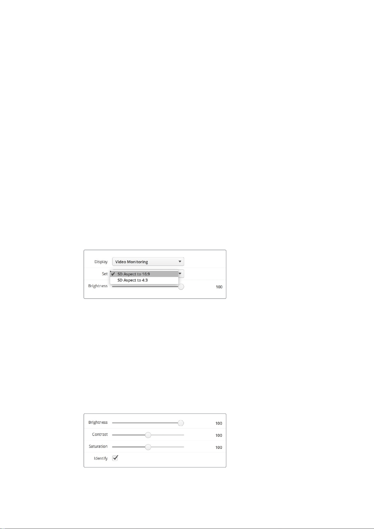
Set
When using a SmartScope, the ‘set’ drop down menu lets you select 4:3 or 16:9 aspect ratios for
the video monitoring display when using standard definition video. The ‘set’ drop down menu
provides additional options for the selected display, including vectorscope, audio dBFS and
audio dBVU options.
Video Monitoring: Select to view thevideo image using 4:3 or 16:9 aspect ratios.
When viewing widescreen anamorphic standard definition video, choose the
16:9aspect ratio. When viewing traditional 4:3 standard definition video, choose the
4:3aspect ratio.
Vectorscope: Select whether your input is based on 100% or 75% color bar test signals.
Audio dBFS: Select which pair of audio channels to monitor phase.
Audio dBVU: Select which pair of audio channels to monitor phase.
Set “SD Aspect to 16:9” when viewing
anamorphic standard definition video
Brightness, Contrast, Saturation
Adjust the sliders to apply brightness, contrast and saturation settings.
Identify Monitor
When the ‘identify’ checkbox is enabled, any monitor selected in Blackmagic SmartView setup
will display a white border. If several SmartView and SmartScope units are connected via a
network, this setting makes it easy to visually identify the selected monitor.
If this setting is used in conjunction with the ‘both monitors’ setting, the white border will be
displayed on both SmartView Duo or SmartScope Duo 4K monitors.
Drag the sliders left and right to adjust brightness,
contrast and saturation settings. Check the Identify
setting to visually identify your selected monitor.
10Using Blackmagic SmartView Setup
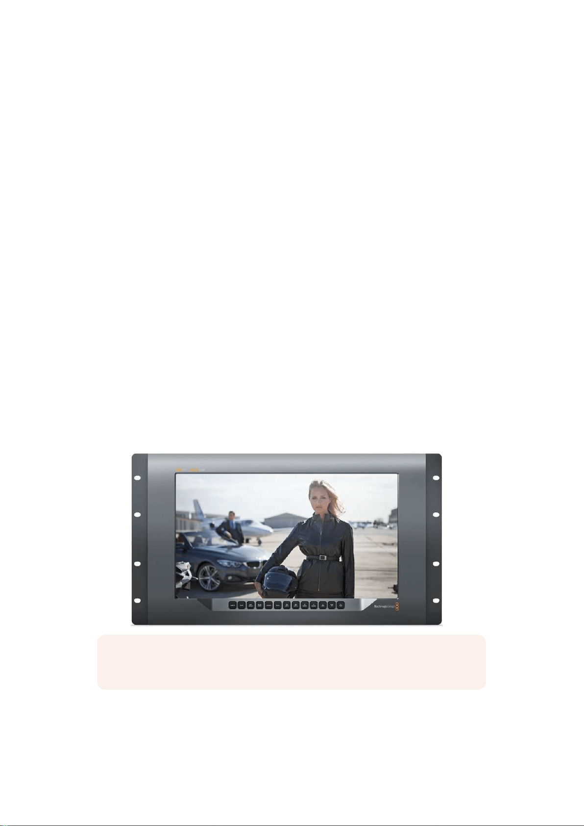
Using SmartView 4K
Introducing Blackmagic SmartView 4K
SmartView 4K is a 6 rack unit Ultra HD 12G-SDI broadcast monitor for displaying SD, HD and
native viewing of up to 2160p60 Ultra HD video. With a bright display and a wide viewing angle,
SmartView 4K provides a vibrant, crystal clear picture for accurate focus and color monitoring,
and supports virtually every video format.
Designed for studio and outside broadcast environments, SmartView 4K is incredibly easy to
use. Featuring side mounted connectors and VESA support, you can fit the unit into tight
spaces, or mounted on a wall or articulated arm. SmartView 4K can be operated using the built
in control panel, or remotely via Ethernet if you don’t have access to the front panel.
Two multi rate 12G-SDI inputs let you select between two SDI sources, plus a SMPTE
compatible SFP module socket so you can add an optical fiber SDI module and connect your
video via optical fiber! A 12G-SDI output is provided so you can feed your video to other
equipment, plus two Ethernet connectors for networking, remote control and loop output for
daisy chaining to other monitors. Other connectors include a tally input for live production,
and a USB port for internal software updates.
You can even load industry standard 3D LUTs with .cube extension or DaVinci Resolve
generated LUTs using the Blackmagic SmartView setup software! With 3D LUTs you can
connect your SmartView 4K directly to your camera and view your clips as close to the final
grade as possible. Two levels of focus peaking let you make sure your shots are in perfect
focus, and with support for AC and DC power you have the option to plug SmartView 4K into
mains power, or an external battery for portability on set.
SmartView 4K is the perfect monitoring solution for portable and studio broadcast production
displaying video in SD, HD, and Ultra HD in its native 3840x2160 pixel resolution.
NOTE If connecting external power via the DC power input, ensure your external
power output is capable of supplying 24 watts at 12 volts.
11Using SmartView 4K
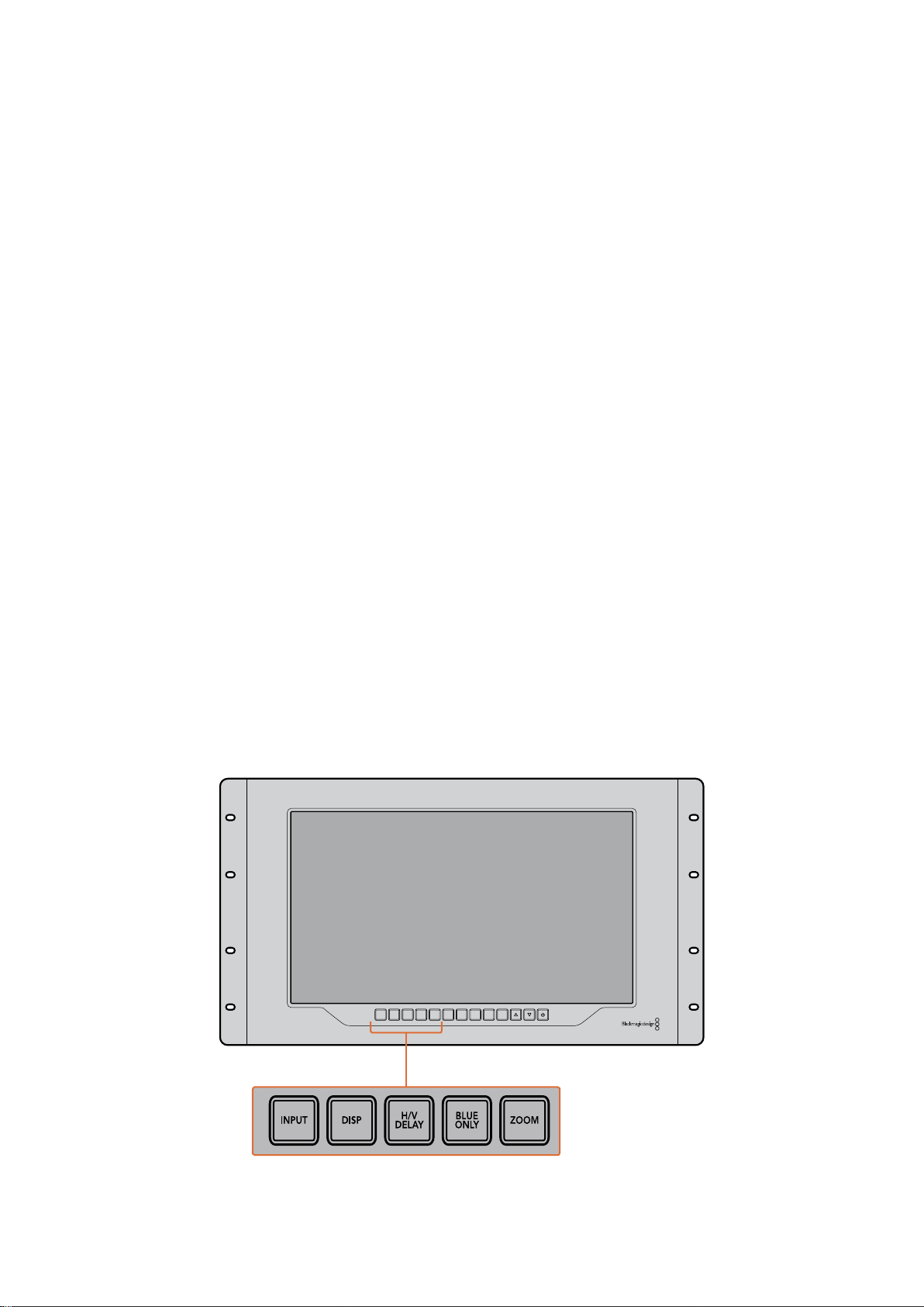
Control Panel Buttons
The control panel features a row of buttons so you can quickly adjust settings on your
SmartView 4K.
Input
Pressing this button cycles through the video signals connected to SmartView 4K’s two 12G-SDI
inputs and optional optical fiber SFP module input. If there is no video connected to an input,
SmartView 4K will display black for that input. When switching between inputs, information
about your connected input format will be momentarily displayed on the top left corner of
your monitor.
Disp
The ‘disp’ button is used to adjust the brightness setting on your SmartView 4K’s LCD. Adjust
brightness by pressing the up and down arrow buttons. Press the ‘disp’ button again to close
the setting.
H/V Delay
Pressing the ‘H/V delay’ button lets you quickly confirm the presence of ancillary data
embedded in your SDI video signal. For example, press the H/V delay button once to view the
horizontal ancillary data. Press the H/V delay button again to view the vertical ancillary data,
commonly used for data such as closed captions.
Blue Only
If the4re is noise in a digital video signal, it is prominently within the blue channel. You can
easily check for noise in your blue channel by pressing the ‘blue only’ button. This displays only
the blue channel represented as a black and white image. This black and white image can also
be used for assistance when checking camera focus.
Zoom
A method of achieving crisp camera focus is to use the ‘zoom’ button. Press once to zoom into
the image. Now you can see clearly if an object is in focus. Press zoom again to return to normal
viewing size.
INPUT DISP
H/V
DELAY
3D
LUT 1
BLUE
ONLY
ZOOM PEAK
3D
LUT 2
H
MARK
V
MARK
12Using SmartView 4K
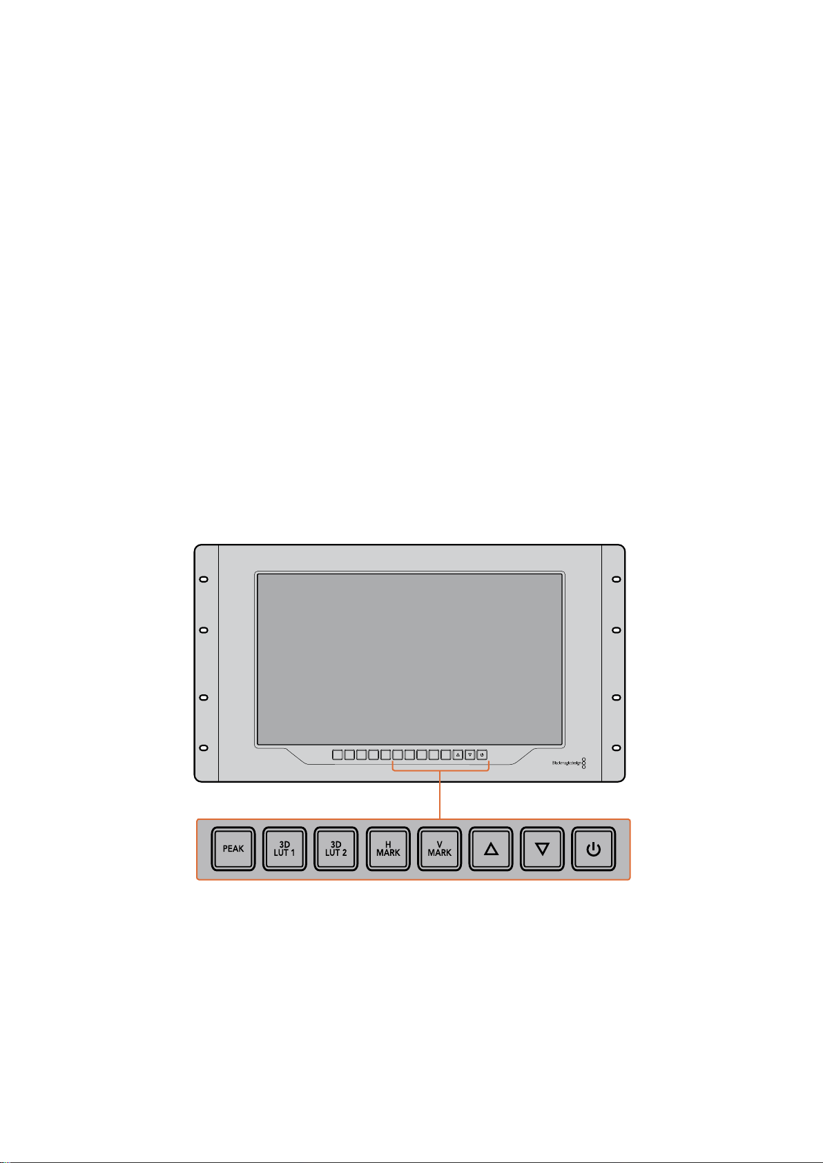
Peak
Camera focus can easily be checked by pressing the ‘peak’ button to enable focus peaking.
This displays a bright green edge around the sharpest points in your image. There are two
levels of peaking strengths which you can cycle through with subsequent pressing of the peak
button. When the green edges are at their strongest, you can be sure your camera is in focus.
3D LUT 1 and 3D LUT 2
The LUT buttons let you view your image using custom 3D LUTs generated in Blackmagic
DaVinci Resolve, or industry standard .cube LUTs. Press a LUT button once to enable the LUT.
Press again to disable the LUT. Refer to the ‘loading 3D LUTs using Blackmagic SmartView
setup’ section for more information on using 3D LUTs with SmartView 4K.
H Mark and V Mark
You can view and edit frame markers using the ‘H Mark’ and ‘V Mark’ buttons. Frame markers
help you compose shots or keep important information or graphics within the safe area of the
screen. Different televisions display slightly more or less of the edges of a video signal, so it’s
handy to view a safe area. A safe area is the section of the screen that will always be visible no
matter what television or monitor is being used to view it.
To view horizontal and vertical frame markers, press the H Mark and V Mark buttons
respectively. To edit the markers, press each respective button again to highlight each guide.
This allows you to edit the markers’ positions using the up and down arrow buttons.
Subsequent presses of each button will confirm your new positions. Another press turns the
markers off.
Up and Down Arrow Buttons
Use the up and down arrow buttons when editing a setting, for example adjusting the display
brightness or editing frame marker positions.
Power
Press the power button once to turn your SmartView 4K on. Press again to turn off.
INPUT DISP
H/V
DELAY
3D
LUT 1
BLUE
ONLY
ZOOM PEAK
3D
LUT 2
H
MARK
V
MARK
13Using SmartView 4K
Loading 3D LUTs using Blackmagic SmartView Setup
SmartView 4K lets you monitor your video using 3D LUTs. This gives you the option to calibrate
your SmartView 4K using professional calibration LUTs, or to view your video as close to your
final grade as possible. You can also use 3D LUTs to experiment with different looks. LUTs are
loaded into SmartView 4K using Blackmagic SmartView setup, and because SmartView 4K
supports industry standard LUT files with a .cube file extension, you can even load custom LUTs
generated with Blackmagic DaVinci Resolve. Refer to the DaVinci Resolve manual for more
information about generating LUT files.
To load a 3D LUT into 3D LUT 1:
1 Launch Blackmagic SmartView setup.
2 Press the ‘load LUT 1’ load button. A window will open asking you for the
location of the LUT file you want to load. Select the desired .cube LUT file,
then press the ‘open’ button.
3 To view the LUT you just loaded, press the 3D LUT 1 button on the
SmartView 4K control panel. Press the button again to turn the LUT off.
Follow the same procedure to load a LUT file into 3D LUT 2.
Use Blackmagic SmartView Setup to load
3D LUTs on your SmartView 4K
14Using SmartView 4K

Using SmartScope Duo 4K
What is Blackmagic SmartScope?
Previously, broadcast quality television and post production scopes were incredibly expensive
custom solutions that only let you see one scope at a time on a tiny screen! Some scopes look
ugly and don’t really look good in front of your client.
With SmartScope Duo 4K you get the addition of waveform monitors which allow you to see any
aspect of your video signal on your dual monitors in real time. Any adjustments made to the
input signal in Blackmagic SmartView setup can immediately be seen on SmartScope Duo 4K!
Furthermore, each input signal can be sent to either monitor via the SDI loop out, meaning you
can use the right hand monitor to display the scope for the signal going into the left
hand monitor.
The scopes displayed by SmartScope Duo 4K are selected in the Blackmagic SmartView setup
software. Select your scopes from the ‘display’ drop down menu.
The information below, and over the next several pages, explains how each scope display is
used so you can get a deeper understanding of how each display can help you.
It’s easy to set your Blackmagic SmartScope Duo 4K to show a different
scope on each monitor using Blackmagic SmartView setup
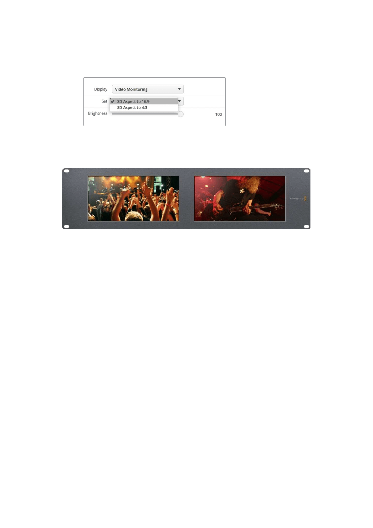
Video Monitoring Display
The Video Monitoring display is a handy confidence monitor so you can see the video that is
being received by SmartScope.
If your input signal is SD, you can select between displaying it in either 4:3 pillarbox or 16:9 from
the ‘set’ drop down menu. Any changes made to the LCD brightness, contrast or saturation
settings can be immediately seen in this view. Note that changing these settings only affects
the monitor, not the video signal, so the scopes will not be affected by any saturation or
brightness changes.
15Using SmartScope Duo 4K
It can often be handy to set one monitor as ‘video monitoring’ and another as your scope view.
To do this, use a short cable to connect the SDI loop out from ‘monitor 1’ to the SDI in of ‘monitor 2’.
You can view SD video in 4:3 pillar box or 16:9
widescreen by selecting from the ‘set’ options in
Blackmagic SmartView setup. Set ‘SD aspect to 16:9’
when viewing anamorphic standard definition video.
The video monitoring display setting shows the video signal
as it will normally appear on a television screen or monitor
Waveform Display
The waveform display provides a digitally encoded waveform similar to traditional luminance
waveform monitors, which is used to monitor and adjust the luma (brightness) levels of your
video signal.
Traditional luminance waveform monitors only supported composite analog standard definition
video. However, SmartScope Duo 4K’s waveform view works in Ultra HD and HD as well as SD
so you have a consistent and easy way to adjust luma levels, even when monitoring high
definition digital video formats!
Select waveform from the display drop down menu in Blackmagic SmartView setup. You will
want to make sure the blacks in your waveform do not drop below 0% and the whites do not
exceed 100% as this means you are getting illegal luma values.
The waveform monitor is a graphical representation of the image, showing luma values in the
same position relative to those within the frame. For example, if part of your sky is overexposed
you will see it in the same horizontal position on the waveform display as it appears in
the frame.
Depending on your footage, your waveform will look different. If you are monitoring video which
is high contrast, you might not see any values in the mid grays. The picture below shows a
waveform for an evenly exposed image with a dark patch on the left, and brighter values from
the centre of the frame out to the right.
16Using SmartScope Duo 4K
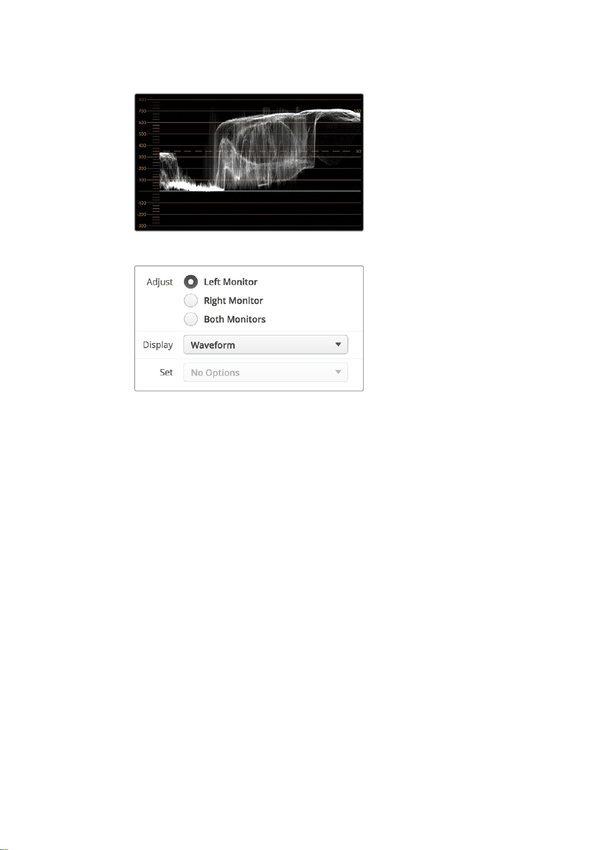
The waveform display showing luminance values
Select ‘waveform’ in Blackmagic SmartView setup ‘display’ settings
to view the luminance values in your video signal
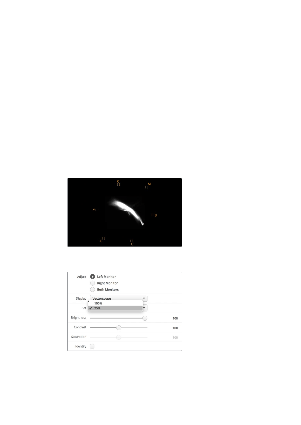
Vectorscope Display
The vectorscope display uses a vector view to show the colors in a video signal. Depending on
the standard of color bar test signals used in your facility, select either 100% or 75% from the
‘set’ drop down menu in Blackmagic SmartView setup.
Some people think you can use a vectorscope to check for illegal levels, however this is not
correct. The Parade RGB display should be used for checking for illegal colors. The reason you
cannot use a vectorscope to check for illegal levels is that both chroma and luminance values
are required. For example, colors near the white or black points in video cannot be as saturated
as the much stronger colors, which can be used in the mid-grays. Because vectorscope display
only shows colors, and not luminance values, it cannot be used solely to check for illegal colors.
Vectorscope display is the best tool for checking color levels from older, analog videotape
where you need to adjust chroma levels. Just play back the color bar segment of the videotape,
and then adjust the chroma and hue settings to set the colors of the video within the square
boxes in the graticule.
17Using SmartScope Duo 4K
Vectorscope display is also perfect for color grading, as you can easily see if your video is
correctly white balanced or if there is a color tint. If your video has a color tint, the vectorscope
display will drift off center, and you might see two center dots. Normally the blanking in the
video signal will create a dot in the center of the vectorscope, and this is because the blanking
in the video is black video without any color. Blanking provides a useful reference point to help
recognize areas of black video without any colorinformation.
If your video has a color tint, you should see the blacks move off color and off center. The
degree of shift represents the amount of color tint in your video and you can see the shift in
both the white and black details of your video. This makes vectorscope display valuable for
removing color tint and regaining correct white balance.
Vectorscope display lets you push colors in your video to the limits, without accidentally adding
unwanted color tints to blacks and whites. While color balance can be monitored on both the
RGB parade display and vectorscope display, color balance issues will often be easier to see in
the vectorscope display.
When color correcting footage of skin tone, particularly faces, you will want to keep your warm
color saturation along a line at approximately 10 o’clock on the vectorscope. This is known as
the “fleshtone line” and is based on the color of blood beneath the skin’s surface. The fleshtone
line is therefore applicable to all skin pigmentations and is the best way to ensure the skin tones
of your talent look natural.
Vectorscope display showing the “fleshtone
line” towards the 10 o’clock position
Set your vectorscope to 100% or 75% color bar test signals
18Using SmartScope Duo 4K
Parade Display
RGB and YUV parade displays are perfect for color correction, checking for illegal colors and
checking levels.
When color correcting, select RGB parade from the ‘display’ drop down menu in Blackmagic
SmartView setup. RGB parade view displays the full height of the individual red, green and blue
color channels. Monitoring the levels of each color channel makes color correction
straightforward and it is also easy to view color balance in the blacks, mids and whites of the
video signal. RGB parade display enables you to identify details common to the red, green and
blue channels, making it simple to color balance and remove unwanted color tints.
It’s important when color correcting to make sure the video levels are full but not clipped. If you
want to increase the video level, make sure it doesn’t go above upper RGB limit or you will
encounter illegal levels. Some equipment won’t let you generate illegal 100% RGB levels,
however other equipment will. SmartScope Duo 4K lets you see illegal levels whenever
they occur.
Illegal video can also happen in the black and white levels. In some color correction systems,
black levels can be lowered to below the black point of 0%. If you observe illegal black levels,
just add some “lift” or gain to eliminate them but check the 100% graticule level to make sure
the whole video signal has not lifted and generated illegal colors in the whites.
To check YUV levels, select YUV parade from the ‘display’ drop down menu. This view is useful
because the luma (brightness) values are separated from the chroma (color) values, which is the
format of video signals for television broadcast. The left waveform shows the luma information
and the second and third waveforms show the chroma information. YUV parade view is useful
for calibrating a video signal’s chroma values to a color bar test pattern, so that colors are
represented accurately and the signal being broadcast will be displayable by television sets.
Color correcting is a constant adjustment process to attain the best looking images without
generating illegal levels!
RGB parade view
Color Correction Terminology
Blacks – Black levels in the video signal
Mids – Mid-gray levels in the video signal
Whites – White levels in the video signal
19Using SmartScope Duo 4K
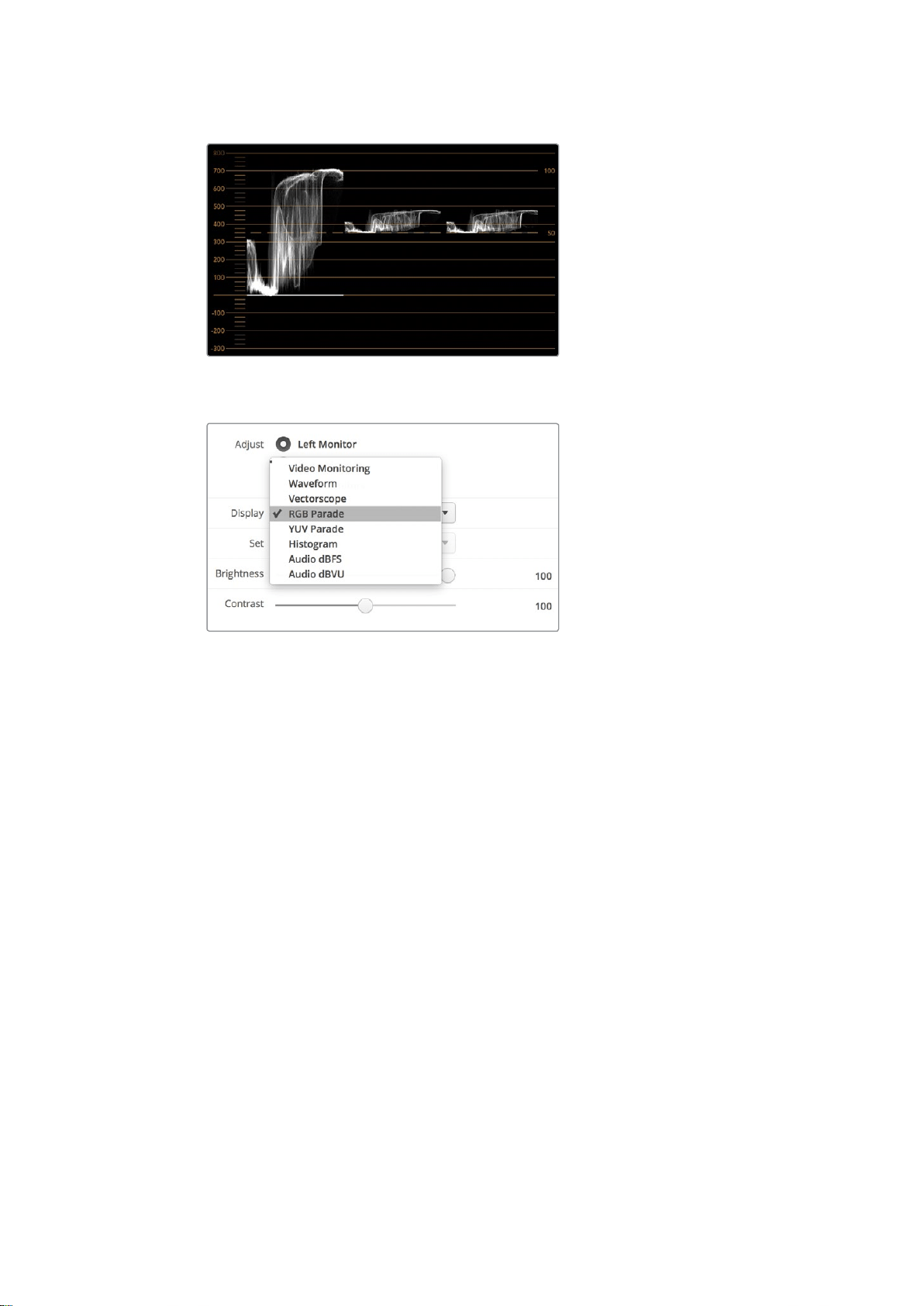
YUV parade view
Select between RGB parade and YUV parade from the ‘display’
drop down menu in Blackmagic SmartView Setup
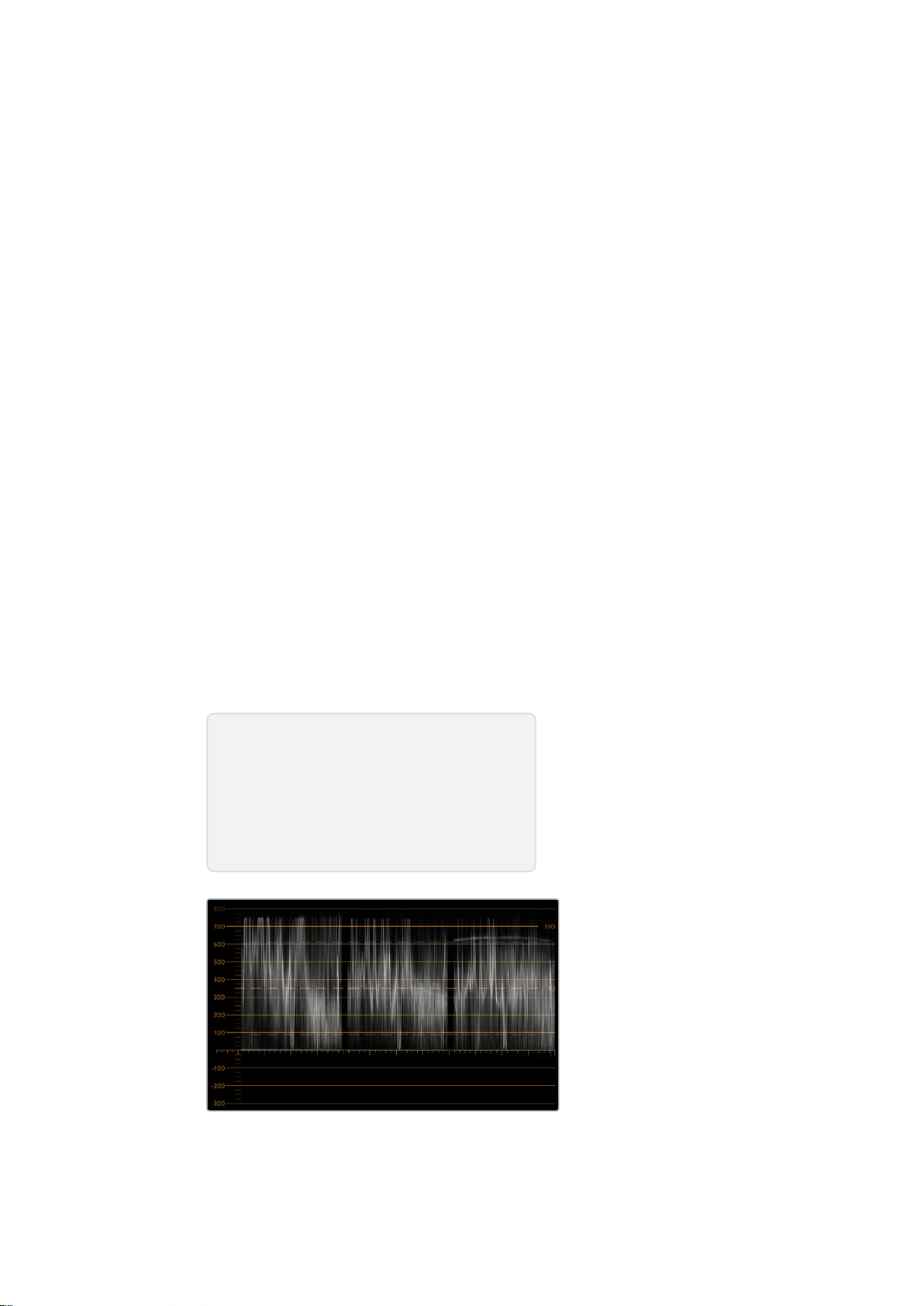
Histogram Display
Histogram display is most familiar to graphic designers and camera operators. Histogram
display shows the distribution of white to black information and lets you monitor how close the
detail is to being clipped off in the whites or blacks of the video. Histogram display also lets you
see the effects of gamma changes in the video.
Black video is shown on the left of the display, and whites are shown on the right. All video
should usually be found between the 0% and 100% intervals of the histogram display. Your
video is being clipped if it moves below 0% or above 100%. Video clipping can be really bad
when you’re on a shoot, as detail in the blacks and whites must be preserved if you
subsequently want to perform color-correction in a controlled environment. When shooting,
keep the video above the black clip, and below the white clip, so you can have more freedom
later to adjust colors without whites and blacks appearing flat and lacking in detail.
When color-correcting, you might decide to clip your video, and in which case histogram display
will show the effect of clipping the video, and how much it is being clipped. You can even use
gamma to create a similar look, with less clipping, while retaining more detail.
You cannot really use histogram display to check for illegal levels although you can use it to see
illegal blacks and whites. Histogram display does not show colors and so the histogram might
appear to show legal levels, even though your video may contain illegal colors. Again, RGB
parade display provides the best way to watch out for illegal levels as it shows them in both the
color and luminance elements of the video signal.
20Using SmartScope Duo 4K

The histogram display setting showing
distribution of whites to blacks
Select histogram from the ‘display’ drop down
menu in Blackmagic SmartView setup
Audio Metering Display
The audio metering displays show you the audio levels in the embedded audio of the SDI video
signal. Up to 16 channels of embedded audio are de-embedded and then displayed in either
dBVU or dBFS format.
The VU meter shows average signal levels, is easy to use and very common on older equipment.
VU is calibrated to the SMPTE recommendation of a 1 kHz tone test signal set to -20 dBFS.
dBFS is essentially a meter of the overall digital audio signal and is common on modern digital
equipment.
The right hand audio scope can monitor two channels of audio, which can be selected from the
‘set’ drop down menu. e.g., ch 1 & 2, ch 3 & 4, etc. The audio scope presents audio in an X-Y
view so you can see audio balance issues, out of phase conditions and whether an audio track
is mono or stereo. Mono audio should appear as a single vertical “in phase” line. If the line is
horizontal, then your audio is “out of phase” and could cancel out (i.e., loss of audio) when
received by downstream equipment. Audio phase is one of the most common audio faults in
large facilities, where cables can be incorrectly connected.
21Using SmartScope Duo 4K

When monitoring stereo signals, the line of the right hand audio scope fans out to represent the
difference between the left and right audio channels. The more stereo sound contained in the
audio track, the more circular the line will appear. If the audio contains minimal stereo content,
then the scope will appear more concentrated around the vertical axis.
Dialog audio tends to appear as a vertical line, whereas music with plenty of stereo content will
cause the scope to puff out. This is because mono audio is L+R, and will display on the vertical
axis, whereas stereo content is L-R, and will display on the horizontal axis to show the stereo
difference.
Audio metering display showing peak levels and audio balance
Use the “Set” drop down menu to select which
pair of audio channels to monitor.
Connecting to a Network
By connecting a SmartView or SmartScope monitor to a network, you can adjust monitor
settings for multiple units remotely.
While SmartView and SmartScope monitors display video without needing any configuration,
any network settings need to be configured prior to deployment. Network configuration can
only be performed using a direct USB connection to a computer.
22Connecting to a Network

Direct Ethernet
Remote monitor configuration can be performed via a direct Ethernet connection to your
computer. No network switch is required in this configuration, which is great if you need to
install and set up quickly. Additional units can be daisy-chained together using the active
loop-through Ethernet out port on each unit. Power must be supplied to all units in the chain.
If you want to connect several units without using IP addresses from your existing studio
network, or if you don’t have an existing network, simply connect them directly to the Ethernet
port on your computer. This is also a fast way to connect SmartView and SmartScope units via
Ethernet as you don’t need to run any cables back to a network switch.
Ethernet Connector
Ethernet Network Switch
If you want to connect several units to your studio’s network, you only need to connect one
SmartView or SmartScope to the network switch and the rest can be daisy-chained to each
other using the active loop-through Ethernet out port on each unit so only a single port on your
switch is used. This way you won’t have to run multiple cables back to a network switch. Power
must be supplied to all units for daisy-chaining to work.
Connecting to a network switch allows any computer on the network to change a unit’s settings.
Any Mac or Windows laptop computer can also change settings via a WiFi connection if your
network includes a wireless access point.
You will need to carry out the following steps to connect SmartView or SmartScope to a local
area IP based network.
1 Securely connect and switch on the power supply included with your unit.
2 Connect the unit to a network switch, or directly to a computer, with a
standard RJ45 Ethernet cable.
23Connecting to a Network

Direct Ethernet Connection Diagram
You can connect the Ethernet port of a computer directly to a unit without needing a network
switch. Additional units can be daisy-chained to each other so you don’t have to run multiple
cables back to a network switch. Power must be supplied to all units.
Ethernet Network Switch Connection Diagram
If you want to connect several units to your studio’s existing network, you only need to connect
one unit to the network switch. The rest can be daisy-chained to each other so you don’t have
to run multiple cables back to a network switch. Power must be supplied to all units.
SmartScope 4KDuo
SmartScope 4KDuo
Network Switch
Ethernet
Client
Computers
24Connecting to a Network

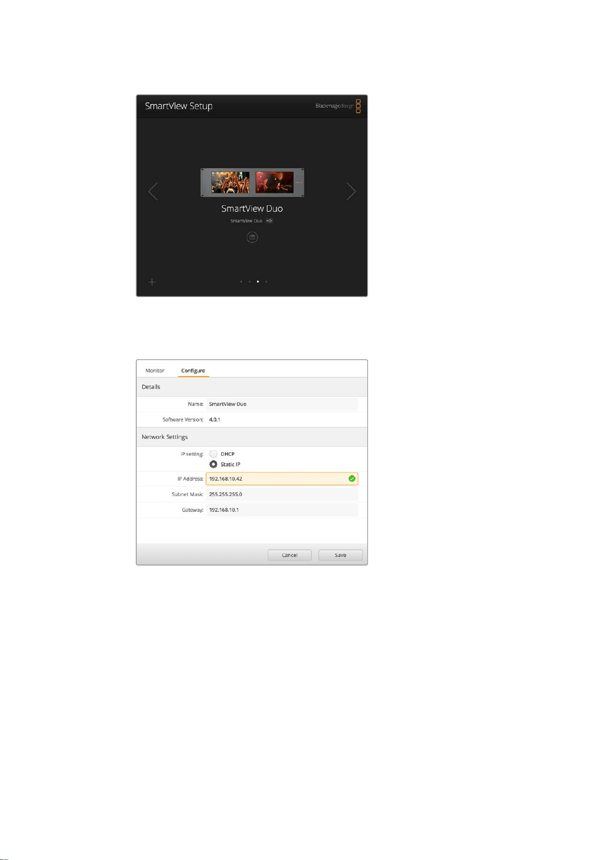
Adjusting Network Settings
Network Settings
Device Name
It is a good idea to change your monitor’s name so each SmartView or SmartScope unit is easy
to identify on a network, e.g., “Field Cameras 1 & 2”, “Multi-View Output”, “4K feeds” etc.
To change your monitor’s name, make sure your monitor is connected via Ethernet or USB.
Launch Blackmagic SmartView setup and click on the settings icon under your monitor name.
Inthe setting page, click network, and edit the name of your monitor located in the ‘details’
section. If the software detects an invalid name, a warning icon will appear next to the name
asyou are typing. If the name is valid, a green tick will appear. Press the ‘return’ key on your
computer keyboard to confirm the name change.
Network Settings
To make changes to the network settings section in Blackmagic SmartView setup, your
Blackmagic monitor must be connected to the computer via USB. Network settings cannot be
changed via Ethernet.
By default, SmartView and SmartScope use DHCP to automatically obtain an IP address from
your network.
In the absence of a DHCP server, you may wish to enable the “internet sharing” feature of
macOS, or the “internet connection sharing” (ICS) feature of Windows 8.1 or Windows 10, to
provide DHCP addresses to any directly attached units. This will avoid having to manually
assign static IP addresses to each unit. You can use this feature to provide DHCP addresses
even though your computer might not have an Internet connection. Internet sharing is detailed
in the macOS and Windows 8.1 and 10 Help documentation.
If DHCP cannot be used in your configuration, choose to configure the address using “static IP”.
Please ask your system administrator for a spare IP address to avoid creating an IP conflict on
your network. You will need to specify a unique IP address for each SmartView and
SmartScope unit as well as a common subnet mask. It is unnecessary to change the default
value in the “gateway” field unless you intend to connect your units to a network gateway such
as an Internet router.
If no SmartView or SmartScope monitors are found on the network, the units might not have
received IP addresses via DHCP and it will be necessary to manually configure each unit with
appropriate network settings.
1 Connect a Blackmagic SmartView or SmartScope monitor to your computer
via USB and launch Blackmagic SmartView setup.
2 Your connected monitor will be automatically displayed in the SmartView
setup home page and will show a USB icon next to its name.
3 Adjust your monitor’s network settings.
4 Repeat these steps for any other units that have not received an IP
address via DHCP.
25Adjusting Network Settings
The USB icon next to your monitor’s name shows that the monitor
is connected to your computer via USB. Your Blackmagic monitor
needs to be connected via USB to adjust network settings.
Network settings can be set to use DHCP or a Static
IP address and can only be changed via USB
Adding a Blackmagic Monitor
If you already know the IP address of a SmartView or SmartScope Duo 4K but it hasn’t
automatically appeared in the Blackmagic SmartView setup home page, you can add the
monitor manually. To do so:
1 Make sure your Blackmagic monitor is connected via Ethernet. Click on
the ‘plus’ icon at the bottom left corner to open the ‘add a Blackmagic
monitor’ window.
2 Type in the IP address of the monitor and click ‘add’.
3 The software will verify the presence of the unit and add it to the
Blackmagic monitors included on the SmartView setup home page. Click
the right arrow icon to see your newly added monitor.
26Adjusting Network Settings

You can manually add a SmartView or SmartScope
monitor to the list of connected monitors by clicking the
‘plus’ icon and entering the monitor’s IP address
Using Tally
Tally Port Pin Connections
It is not necessary to connect the tally port of SmartView or SmartScope and you can skip this
section if you do not intend to use the tally feature.
Each SmartView and SmartScope screen features independent tally borders in red, green
or blue which can be used to indicate the status of a video signal such as on-air, preview
orrecording.
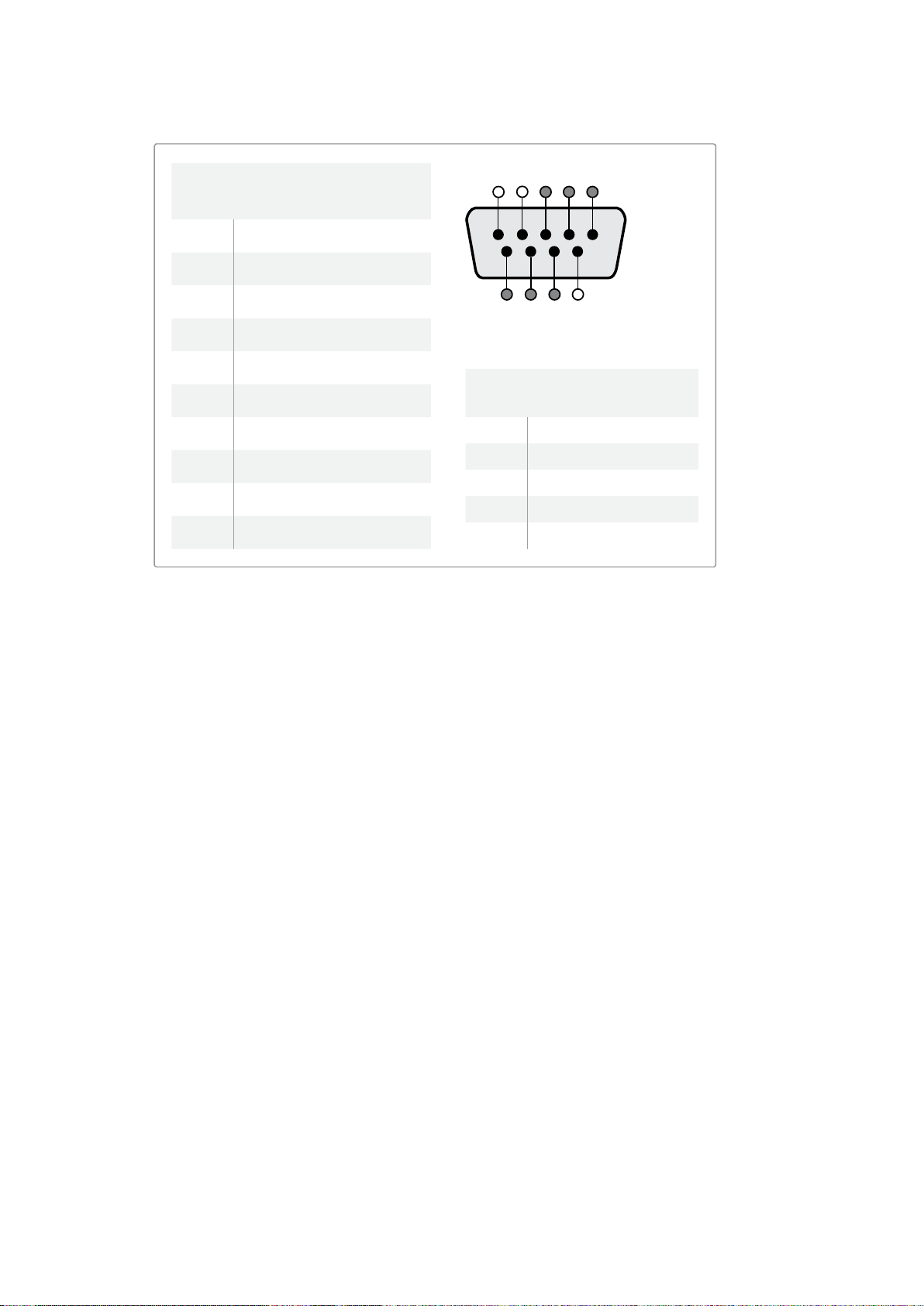
The 9-pin D-sub tally port accepts contact closure signals from switchers and automation
systems. Please refer to the accompanying tally pin connections diagram for information
aboutwiring the tally port for use with your switcher or automation system.
The 9-pin D port wiring description is printed on the rear of the unit showing contact closures
to display red, green or blue tally borders on each independent monitor.
SmartView Duo showing green and red tally borders
27Using Tally
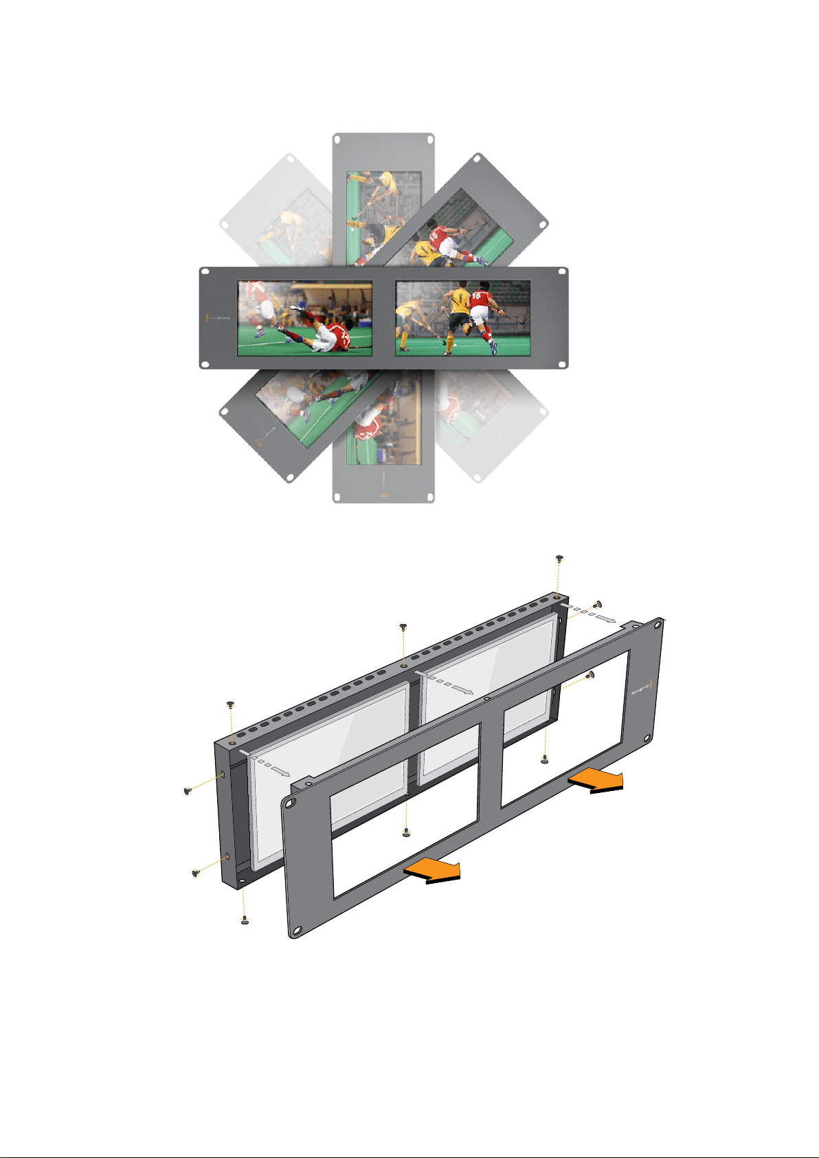
Optimizing the Viewing Angle
If SmartView Duo, SmartView HD or SmartScope monitors are to be installed high up in an
equipment rack, you may wish to physically invert the LCDs for the optimum viewing angle.
The images on the LCDs will automatically flip to the correct orientation when they sense an
inversion. A number 02 size pozidriv screwdriver is required to disconnect and reconnect the
faceplate from its rear assembly. This is a simple procedure and does not involve opening the
rear assembly.
The following procedure describes how to invert the unit while keeping the Blackmagic Design
logo in the correct orientation on the faceplate. A number 02 size pozidriv screwdriver
is required.
1 Remove the screws from the top, bottom, left and right sides of the
faceplate. SmartView Duo and SmartScope Duo 4K have 10 screws and
SmartView HD has 18 screws.
2 Lift the front faceplate away from the rear assembly as illustrated.
3 Invert the rear assembly.
4 Reinstate the faceplate on the inverted rear assembly.
5 Reinstate the screws in the chassis.
Your SmartView or SmartScope is now ready to be installed high up in a rack. Once bolted into
a rack, SmartView will continue to display the optimum viewing angle even if bumped, as there
are no external knobs or adjustments to mishandle or to come loose.
SmartView Duo and SmartScope Duo 4K
Tally Pin Connections
Pin Function
1 Monitor 1 Red
2 Monitor 1 Green
3 Monitor 1 Blue
4 Ground
5 Ground
6 Ground
7 Monitor 2 Red
8 Monitor 2 Green
9 Monitor 2 Blue
SmartView HD and SmartView 4K
Tally Pin Connections
Pin Function
1 Red
2 Green
3 Blue
4 Ground
5 4 3 2 1
9 8 7 6
SmartView Tally-Port
28
Optimizing the Viewing Angle

Developer Information
Developing Custom Software Using Blackmagic Design Hardware
The Blackmagic SmartView Ethernet Protocol allows developers to remotely control Blackmagic
SmartView and SmartScope hardware with their own custom software. The Blackmagic
SmartView Ethernet Protocol is a text-based status and control protocol.
Downloading the Free SmartView EthernetProtocol
The Blackmagic SmartView Ethernet Protocol is free. It is included in this SmartView &
SmartScope manual and can be downloaded from www.blackmagicdesign.com/support
Joining the Blackmagic Design Developer List
The Blackmagic Developer mailing list is designed for technical questions regarding
technologies used by Blackmagic Design, e.g., QuickTime, Core Media, DirectShow, codecs,
APIs, SDKs, etc. The free mailing list is a forum where developers can discuss ideas and
problems with other developers. Any subscriber may reply and the Blackmagic Design
engineers may also respond when appropriate. You can subscribe to the mailing list at:
http://lists.blackmagicdesign.com/mailman/listinfo/bmd-developer
In some cases, we might request a brief outline of the software you are developing if it is not
immediately obvious from your domain name that your organization develops video software.
Please don’t take offence as we’re simply trying to keep the list free of spam and viruses as well
as end-user customers asking non-development questions, employment agents or sales
people trying to promote products on the list. The list is just for developers.
Contacting Blackmagic Design DeveloperAssistance
You can also contact us via developer@blackmagicdesign.com if you have any developer
related questions or wish to ask questions off the list.
Blackmagic 2K Format – Overview
Blackmagic Design products support 3G-SDI video, which allows twice the data rate of
traditional HD-SDI video. We thought it would be a really nice idea to add 2K film support,
via 3G-SDI technology, so we could simplify feature film workflows. With the popularity of
Blackmagic Design editing systems worldwide, now thousands of people can benefit from
a feature film workflow revolution.
30Developer Information
This information includes everything product developers need to know for building native
2KSDI equipment. Of course, all Blackmagic products can be updated, so if the television
industry adopts an alternative SDI-based film standard, we can add support for that too!
Frame Structure
Transmitted at 23.98, 24 or 25 frames per second as a Progressive Segmented Frame.
Active video is 2048 pixels wide by 1556 lines deep.
Total lines per frame : 1650
Active words per line are 1535. One word consists of a 10-bit sample for each of the
four data streams, i.e., a total of 40 bits. See the diagram named Blackmagic 2K Format
- Data Stream Format.
Total active lines : 1556
Total words per line : 1875 for 23.98/24Hz and 1800 for 25Hz.
Fields per frame : 2, 825 lines each
Active lines located on lines 16-793 (field 1) and 841-1618 (field 2).
Transport Structure
Based on SMPTE 372M Dual Link mapping and SMPTE 425M-B support for mapping
SMPTE 372M into a single 3 Gb/s link.
Timing reference signals, line number and line CRC insertion is the same as above.
During active video, 10-bit Red, Green and Blue data is sent in the following sequence:
Optional ancillary data is inserted into both virtual interfaces.
At present, only audio data is included: as per standard HD audio insertion (SMPTE
S299M) the audio data packets are carried on data stream two and audio control
packets are carried on data stream one.
Data stream 1: Green_1, Green_2, Green_3, Green_5...Green_2047
Data stream 2: Blue_1, Blue_2, Green_4, Blue_5...Green_2048.
Data stream 3: Red_1, Blue_3, Blue_4, Red_5...Blue_2048.
Data stream 4: Red_2, Red_3, Red_4, Red_6...Red_2048.
Blackmagic 2K Format – Vertical Timing Reference
This diagram shows the vertical timing details with line numbers and Field, Vertical and
Horizontal bits for the Timing Reference Signal codes.
Field 1 Active
F 1 0 0 0 0 0 0 0 0 0 0 0
V 1 1 1 1 1 1 0 0 0 0 1 1
LINE # 1650 1 2 ... 14 15 16 ... 792 793 ... 825
Field 2 Active
F 0 1 1 1 1 1 1 1 1 1 1 1
V 1 1 1 1 1 1 0 0 0 0 1 1
LINE # 825 826 827 ... 839 840 841 ... 1617 1618 ... 1650
31Developer Information

Blackmagic 2K Format – Data Stream Format
This diagram shows the data stream formats around the optional ancillary data section of the
horizontal line. Note that each active pixel takes up three samples.
Data Stream 1
G2041
G2042
G2043
G2045
G2046
G2047
EAV(3FFh)
EAV(000h)
EAV(000h)
EAV(XYZh)
LN0
LN1
CRC0
CRC1
ANC/Audio
Data
SAV(3FFh)
SAV(000h)
SAV(000h)
SAV(XYZh)
G1
G2
G3
G5
Data Stream 2
B2041
B2042
G2044
B2045
B2046
G2048
EAV(3FFh)
EAV(000h)
EAV(000h)
EAV(XYZh)
LN0
LN1
CRC0
CRC1
ANC/Audio
Data
SAV(3FFh)
SAV(000h)
SAV(000h)
SAV(XYZh)
B1
B2
G4
B5
Data Stream 3
R2041
B2043
B2044
R2045
B2047
B2048
EAV(3FFh)
EAV(000h)
EAV(000h)
EAV(XYZh)
LN0
LN1
CRC0
CRC1
040
…
040
SAV(3FFh)
SAV(000h)
SAV(000h)
SAV(XYZh)
R1
B3
B4
R5
Data Stream 4
R2042
R2043
R2044
R2046
R2047
R2048
EAV(3FFh)
EAV(000h)
EAV(000h)
EAV(XYZh)
LN0
LN1
CRC0
CRC1
200
…
200
SAV(3FFh)
SAV(000h)
SAV(000h)
SAV(XYZh)
R2
R3
R4
R6
Word#
23.98/24 PsF
1870
1871
1872
1873
1874
1875
1
2
3
4
5
6
7
8
9
…
335
336
337
338
339
340
341
342
343
Word#
25 PsF
1795
1796
1797
1798
1799
1800
1
2
3
4
5
6
7
8
9
…
260
261
262
263
264
265
266
267
268
32Developer Information

Blackmagic SmartView Ethernet Protocol v1.3
Summary
The Blackmagic SmartView Ethernet Protocol is a text-based status and control protocol, very
similar in structure to the Videohub protocol, that is accessed by connecting to TCP port 9992
on a SmartView or SmartScope device.
Upon connection, the SmartView or SmartScope device sends a complete dump of the state
of the device. After the initial dump, state changes are sent asynchronously.
The device sends information in blocks which have an identifying header, followed by a colon.
A block can span multiple lines and is terminated by a blank line.
To be resilient to future protocol changes, clients should ignore blocks they do not recognize,
up to the trailing blank line. Within recognized blocks, clients should ignore lines they do not
recognize.
Version 1.3 of the Blackmagic SmartView Ethernet
Protocol was released with SmartView 1.3 software.
Protocol Preamble
The first block sent by the SmartView Server is always the protocol preamble:
PROTOCOL PREAMBLE:
↵
Version: 1.3
↵
↵
The version field indicates the protocol version. When the protocol is changed in a compatible
way, the minor version number will be updated. If incompatible changes are made, the major
version number will be updated.
Device Information
The next block contains general information about the connected SmartView or SmartScope
device.
SMARTVIEW DEVICE:
↵
Model: SmartView Duo
↵
Hostname: stagefront.studio.example.com
↵
Name: StageFront
↵
Mo nitor s: 2
↵
Inverted: false
↵
↵
This example shows the output for a SmartView Duo device, which has two LCDs.
The INVERTED flag indicates whether the device has detected that it has been mounted in an
inverted configuration to optimize LCD viewing angle.
Legend
↵
carriage return
… and so on
33Developer Information

Network Configuration
The next block shows the TCP/IP networking configuration:
NETWORK:
↵
Dynamic IP: true
↵
Static address: 192.168.2.2
↵
St atic netm as k: 255.255.255.0
↵
St atic gatew ay: 192.168.2.1
↵
C u rr e nt ad d r e ss: 192.168.1.101
↵
C u rr e nt netm a sk: 255.255.255.0
↵
C u rr e nt g ate w ay: 192.168.1.1
↵
↵
The network settings prefixed with CURRENT show the active TCP/IP settings, and are read-
only. The CURRENT settings reflect either the DHCP or Static configuration, depending on the
DYNAMIC IP flag.
Changing Networking Settings
The network can be configured to use either DHCP or a static configuration. To enable DHCP:
NETWORK:
↵
Dynamic IP: true
↵
↵
To set a fixed IP address, supply all static parameters, thus:
NETWORK:
↵
Dynamic IP: false
↵
Static address: 192.168.2.2
↵
St atic netm as k: 255.255.255.0
↵
St atic gatew ay: 192.168.2.1
↵
↵
The parameters with the CURRENT prefix are read-only, and show the active configuration,
regardless of the static or dynamic setting.
Changing the device name, or any network settings, will cause the IP connection to be
dropped. The device will restart its networking and advertise its new name on the network.
Changing Monitor Settings
The display settings for each monitor are specified individually. One or more parameters can
be modified at the same time and multiple settings can be supplied in one block.
The valid range for numeric values is 0-255. The CONTRAST and SATURATION properties are
zero-centered, so the normal value is 127, such that the displayed picture is the same as the
original. A value greater than 127 in either channel will cause the contrast or saturation to be
increased, and similarly a value less than 127 will cause a decrease.
For example, to set the brightness to 50% and desaturate the image to Black & White:
MONITOR A:
↵
Brightness: 127
↵
Saturation: 0
↵
↵
34Developer Information

Displaying SD in 16:9
The following command sets standard definition video to display in 16:9:
MONITOR A:
↵
WidescreenSD: ON
↵
Displaying SD in 4:3
The following command sets standard definition video to display in 4:3:
MONITOR A:
↵
WidescreenSD: OFF
↵
Identification and Tally Settings
The Identify flag is transient, and will cause a white border to be displayed around the entire
picture for a duration of 15 seconds, after which it will be reset. This feature is primarily aimed at
identifying which monitor is currently being configured when it is mounted in a rack comprising
multiple units. To turn on:
MONITOR A:
↵
Ide ntify: tr u e
↵
↵
The IDENTIFY border will temporarily override any other border setting in effect.
The BORDER property can be used to programmatically set the soft Tally colored borders to
one of the primary colors: RED, GREEN, BLUE, WHITE or NONE. This setting can be overridden
by the electrical Tally signals at the DB-9 input on the device itself. For example, to set the soft
Tally to green:
MONITOR B:
↵
Border: green
↵
↵
The hard wired tally will always override the soft tally. The full state report will always show the
current valid border.
SmartScope Settings
On SmartScope Duo 4K, each monitor can be set to display a different scope. The values for
activating specific scopes are mapped as follows:
AudioDbfs
AudioDbvu
Histogram
ParadeRGB
ParadeYUV
Picture (This is the same as Video Monitor)
Vector100
Vector75
WaveformLuma
MONITOR A:
↵
ScopeMode: Picture
↵
↵
In the example above, Monitor A has been set as a video monitor.
35Developer Information

Displaying SD in 16:9
The set Video Monitor mode to display standard definition video in 16:9:
MONITOR A:
↵
ScopeMode: Picture
↵
WidescreenSD: ON
↵
Displaying SD in 4:3
To set Video Monitor mode to display standard definition video in 4:3:
MONITOR A:
↵
ScopeMode: Picture
↵
WidescreenSD: OFF
↵
When setting one of SmartScope Duo 4K’s monitors to audio metering, you can also select
which channels to show. The values for selecting which audio channels are mapped in the
following way:
0: Channels 1 and 2
1: Channels 3 and 4
2: Channels 5 and 6
3: Channels 7 and 8
4: Channels 9 and 10
5: Channels 11 and 12
6: Channels 13 and 14
7: Channels 15 and 16
MONITOR B:
↵
ScopeMode: AudioDbvu
↵
AudioChannel: 0
↵
↵
In the example above, Monitor B has been selected to display Audio Metering in Dbvu with
audio channels 1 and 2 selected for the phase meter.
Selecting LUTs for SmartView 4K
To select 3D LUTs using SmartView 4K:
MONITOR A:
↵
LUT: 0 LUT 1
1 LUT 2
NONE DISABLE
↵
↵
36Developer Information

Help
Getting Help
There are four Steps to Getting Help.
1 Check out the Blackmagic Design support center at
www.blackmagicdesign.com/support for the latest support information.
2 Call your Blackmagic Design reseller.
3 Your local reseller will have the latest technical updates from
Blackmagic Design and should be able to give you immediate assistance.
We also recommend you check out the support options your reseller
offers as they can arrange various support plans based on your workflow
requirements.
4 The next option is to email us with your questions using the “send us an
email’ button at www.blackmagicdesign.com/support
5 Phone a Blackmagic Design support office. You can find your nearest
office by clicking on the “find your local support team” button at the bottom
of the support page.
Please provide us with as much information as possible regarding your technical problem and
system specifications so that we may try to respond to your problem as quickly as possible.
37Help
Regulatory Notices andSafetyInformation
Regulatory Notices
Disposal of waste of electrical and electronic equipment within the European union.
The symbol on the product indicates that this equipment must not be disposed of with
other waste materials. In order to dispose of your waste equipment, it must be handed
over to a designated collection point for recycling. The separate collection and
recycling of your waste equipment at the time of disposal will help conserve natural
resources and ensure that it is recycled in a manner that protects human health and the
environment. Formore information about where you can drop off your waste
equipment for recycling, please contact your local city recycling office or the dealer
from whom you purchased the product.
This equipment has been tested and found to comply with the limits for a Class A digital
device, pursuant to Part 15 of the FCC rules. These limits are designed to
providereasonable protection against harmful interference when the equipment is
operated in a commercial environment. This equipment generates, uses, and can
radiate radio frequency energy and, if not installed and used in accordance with the
instructions, maycause harmful interference to radio communications. Operation of this
product in a residential area is likely to cause harmful interference, in which case the
user will be required to correct the interference at personal expense.
Operation is subject to the following two conditions:
1 This device may not cause harmful interference.
2 This device must accept any interference received, including interference that may
cause undesired operation.
Safety Information
This equipment must be connected to a mains socket outlet with a protective
earthconnection.
To reduce the risk of electric shock, do not expose this equipment to dripping
orsplashing.
This equipment is suitable for use in tropical locations with an ambient temperature
of up to 40ºC.
Ensure that adequate ventilation is provided around the product and is not restricted.
When rack mounting, ensure the ventilation is not restricted by adjacent equipment.
No operator serviceable parts inside. Refer servicing to your local Blackmagic Design
service centre.
Use only at altitudes not more than 2000m above sea level.
This product has the facility to connect small form-factor transceiver (SFP) optical fibre
modules. Only use Laser class 1 optical SFP modules.
Recommended Blackmagic Design SFP modules:
3G-SDI: PL-4F20-311C
6G-SDI; PL-8F10-311C
38Regulatory Notices andSafetyInformation

Warnings for Authorized Service Personnel
Disconnect power from both power inlets before servicing!
Caution - Double Pole/ Neutral Fusing
The power supply contained in this equipment has a fuse in both line
andneutral conductors and is suitable for connection to the IT power
distributionsystemin Norway.
Warranty
12 Month Limited Warranty
Blackmagic Design warrants that this product will be free from defects in materials and workmanship
for a period of 12 months from the date of purchase. If a product proves to be defective during this
warranty period, Blackmagic Design, at its option, either will repair the defective product without
charge for parts and labor, or will provide a replacement in exchange for the defective product.
In order to obtain service under this warranty, you the Customer, must notify Blackmagic Design
of the defect before the expiration of the warranty period and make suitable arrangements for the
performance of service. The Customer shall be responsible for packaging and shipping the
defective product to a designated service center nominated by Blackmagic Design, with shipping
charges pre paid. Customer shall be responsible for paying all shipping charges, insurance, duties,
taxes, and any other charges for products returned to us for any reason.
This warranty shall not apply to any defect, failure or damage caused by improper use or improper
or inadequate maintenance and care. Blackmagic Design shall not be obligated to furnish service
under this warranty: a) to repair damage resulting from attempts by personnel other than
Blackmagic Design representatives to install, repair or service the product, b) to repair damage
resulting from improper use or connection to incompatible equipment, c) to repair any damage or
malfunction caused by the use of non Blackmagic Design parts or supplies, or d) to service a
product that has been modified or integrated with other products when the effect of such a
modification or integration increases the time or difficulty of servicing the product. THIS WARRANTY
IS GIVEN BY BLACKMAGIC DESIGN IN LIEU OF ANY OTHER WARRANTIES, EXPRESS OR IMPLIED.
BLACKMAGIC DESIGN AND ITS VENDORS DISCLAIM ANY IMPLIED WARRANTIES OF
MERCHANTABILITY OR FITNESS FOR A PARTICULAR PURPOSE. BLACKMAGIC DESIGN’S
RESPONSIBILITY TO REPAIR OR REPLACE DEFECTIVE PRODUCTS IS THE WHOLE AND EXCLUSIVE
REMEDY PROVIDED TO THE CUSTOMER FOR ANY INDIRECT, SPECIAL, INCIDENTAL OR
CONSEQUENTIAL DAMAGES IRRESPECTIVE OF WHETHER BLACKMAGIC DESIGN OR THE
VENDOR HAS ADVANCE NOTICE OF THE POSSIBILITY OF SUCH DAMAGES. BLACKMAGIC
DESIGN IS NOT LIABLE FOR ANY ILLEGAL USE OF EQUIPMENT BY CUSTOMER. BLACKMAGIC
IS NOT LIABLE FOR ANY DAMAGES RESULTING FROM USE OF THIS PRODUCT. USER OPERATES
THIS PRODUCT AT OWN RISK.
© Copyright 2018 Blackmagic Design. All rights reserved. ‘Blackmagic Design’, ‘DeckLink’, ‘HDLink’, ‘Workgroup Videohub’,
‘Multibridge Pro’, ‘Multibridge Extreme’, ‘Intensity’ and ‘Leading the creative video revolution’ are registered trademarks in the
US and other countries. All other company and product names may be trade marks of their respective companies with which
they are associated.
39Warranty


ようこそ
最高品質のビデオを誰もが利用できるようにすることで、テレビ業界を真にクリエイティブな業界
にするという私たちの夢をユーザーの皆様と共有できればと考えています。
放送局やスタジオでは、あらゆる場所でビデオモニタリングが必要になります。
SmartView
4K
は
ネイティブ
4K
の
LCD
を搭 載しているため 、
Ultra
HD
ビデオをフル解像度でモニタリングでき、スタ
イリッシュな
6U
ラックサイズの筐体にはコントロールパネルが搭載されているため、すばやく設
定が 変 更できます。
SmartView
HD
は、奥行き
1
インチ未満の
6U
ラックサイズの筐体に
17
インチの
LCD
スクリーンを搭 載しています。
SmartView
Duo
は、奥行き
1
インチ未満の
3U
ラックサイズの筐
体に、
2
面の完全に独立した機能的な
8
インチ
LCD
スクリーンを搭載しています。
SmartScope
Duo
4K
は、波形スコープ機能に対応した
2
面の独立した
8
インチ
LCD
スクリーンを搭 載しているの で、
ビデオレベルをオンザフライでモニタリングできます。すべての
SmartView
モニターは、
3G-SDI
イン
ターフェースを搭載し、
SD
、
HD
、
2K
に対応しています。
SmartScope
Duo
4K
および
SmartView
4K
は、それぞれ
6G-SDI
または
12G-SDI
インターフェースを搭載し、
Ultra
HD
4K
に対応しています。
これらのモニターは、箱から取り出してすぐに使用できるよう設計されています。同梱の
Blackmagic
SmartView
Setup
ソフトウェアは、直感的なコンフィギュレーション・ツールを搭載しています。
このマニュアルには、
SmartView/SmartScope
のインストールに必要な情報がすべて記載されてい
ます。しかし、
IP
アドレスやコンピューターネットワークに関してあまり詳しくない場合は、技術的な
アシストを専門家から得ることもお勧めします。
SmartView/SmartScope
は簡単にインストールで
きますが、インストール後に少し技術的な環境設定が必要になることがあります。
インストールの所要時間は約
5
分 で す。弊社 の ウェブ サ イト
www.blackmagicdesign.com/jp
の
サポートページで、このマニュアルと
SmartView
ソフトウェアの最新バージョンをダウンロードしてく
ださい。最後に、ソフトウェア・アップデートをダウンロードする際に製品のユニットを登録いただ
ければ、新しい ソフ ト ウェアのリ リ ー ス時にお知ら せいたします 。常に新機能の開発および製品の
改善に努めていますので、ユーザーの皆様からご意見をいただければ幸いです。
グラント・ペティ
Blackmagic
Design
CEO

目次
SmartView
&
SmartScope
はじめに 43
SmartView、SmartScopeとは 43
ビデオソースを接続 44
コンピューターを接続 44
Blackmagic
SmartView Setupのインストール 45
BlackmagicSmartViewSetupの使用 46
ソフトウェア・アップデート
46
モニター設定の調整 46
SmartView4Kの使用 49
Blackmagic SmartView 4Kについて 49
コントロールパネルボタン 50
Blackmagic
SmartView Setupで3D LUTをロード 52
SmartScopeDuo4Kの使用 53
Blackmagic SmartScopeとは 53
ビデオモニタリング表示 53
波形表示 54
ベクトルスコープ 表 示 55
パレード表示 57
ヒストグラム表示 58
オーディオメーター表示 59
ネットワークに接続 60
ダイレクト・イーサネット
61
イーサネット・ネットワー クスイッチ 61
ネットワーク設定の調整 63
ネットワー ク設 定
63
Blackmagic
モニターの追加 64
タリーの使用 65
タリーポートのピン接続
65
ビューアングルの最適化 66
デベロッパーの皆様へ 68
Blackmagic 2K Format
–
Overview 68
Blackmagic
2K Format
–
Vertical Timing Reference 69
Blackmagic
2K Format
–
Data Stream Format 70
Blackmagic
SmartView Ethernet Protocol v1
.
3 71
ヘルプ 75
規制に関する警告および安全情報 76
保証 77
43
はじめに
はじめに
SmartView
、
SmartScope
とは
SmartView
モニターは、ラックベースのモニタリングを必要とする、あらゆるスタジオに最適です。電源を
入れて
SDI
ソースを接続するだけで、起動
/
操作が 可能になります。
SmartView
4K
は、
15.6
インチの
4K
LCD
を搭 載しているため、
SD
、
HD
、
Ultra
HD
ビデオをネイティブ
3840x2160
解像度でモニタリングできます。フロントコントロールパネルのボタンで、入力の選択、画面
の明るさの調整、ブルーチャンネルのノイズチェック、ブランキング情報の確認、
3D
LUT
の適用などが簡
単に実行できます。
SmartView
HD
は、
17
インチの
LCD
スクリーンを搭載しており、フル解像度
HD
のモニタリングが 可能です。
SmartView
Duo
は、
2
面のモニターを搭載しており、異なるビデオ信号を同時に表示できます。例えば、
1
面のモニターで
YUV
4:2:2
信号を表示し、もう
1
面で
RGB
4:4:4
を表示したり、片方で
NTSC
を表示し、もう
一方で
PAL
を表示することもできます。このように様々なコンビネーションの信号を表示できますが、操
作自体は、
SDI
ケーブルを各モニターに接続するだけなので非常に簡単です。
SmartScope
Duo
4K
は、
SmartScope
Duo
と同じ機能を搭載しています。それに加え、波形やベクトルス
コープなどのスコープを使用してビデオやオーディオレベルをリアルタイムでモニタリングできます。
また、
Ultra
HD
4K
もフルサポートしています!
SmartView/SmartScope
モニターのすべての
SDI
入力は、
2K
ビデオを含め、
SD
、
HD
、
3G-SDI
の自動検出
に対応しています。
SmartView
4K
は、
12G-SDI
インターフェースを搭 載し、
2160p60
などの
Ultra
HD
フォー
マットも検出します。
SmartScope
Duo
4K
は、
6G-SDI
インターフェースを搭載し、
Ultra
HD
4K
ビデオを
自動検出します。
複数の
SmartView/SmartScope
の設定を
1
台のコンピューターからリモート調整したい場合は、イーサネッ
トを介して接続できます。つまり、設定を調整する際も、コンピューターや
USB
ケーブルを手に各ユニット
間を走り回る必要はありません。
では実際に製品を使用してみましょう。
SmartView/SmartScope
の接続、
Blackmagic
SmartView
Setup
でのモニター設定、およびネットワークへの接続に関する詳細は、このマニュアルに後述されています。
SmartView 4K SmartView HD
SmartView Duo SmartScope Duo 4K
44
はじめに
ビデオソースを接続
SmartView/SmartScope
モニターは、標準の
BNC
端子を搭載しており、スイッチャー、カメラ、キャプチャ
ーカード、デッキ、ディスクレコーダーなど、あらゆる
SDI
機 器を接続 できます。
映像の受信
ビデオの表示は非常に簡単です。ユニットの電源を入れてビデオソースを
SDI
入力に接続するだけで、す
ぐにビデオが画面に表示されます。
SDI
入力およびループスルー出力は、
SD
、
HD
、
2K
信号を自動検出し
ます。
SmartView
4K
および
SmartScope
Duo
4K
は、
Ultra
HD
4K
も自動検出します。
ユニットが映像を受信していない場合、節電のためバックライトが消えますが、有効な信号を受信すると
再び点 灯します。
モニターをデイジーチェーンで接続
SmartView/SmartScope
モニターは、それぞれ独立した
SDI
入力とループスルー出力を搭載しているの
で、複数のモニターをチェーン接続して同じ入力信号を表示できます。
1
ユニット
1
の電源を入れます。ビデオソースを
SDI
入力に接続します。ビデオが即座にスクリー
ンに表示されます。
2
ユ ニット
2
の電源を入れ、ユニット
1
のループスルー出力の
SDI
ケーブルを、ユニット
2
の
SDI
入力に
接 続します。
この方法で、ユニット数に制限なくチェーン接続できます。
SmartScope
Duo
4K
で波形モニタリングしている場合、モニター
1
の出力をモニター
2
にループすると、両
方のスクリーンで同じ入力信号をモニタリングできます。
映像が表示されたら、モニター設定を調整します。あるいは、
SmartScope
Duo
4K
では、
Blackmagic
SmartView
Setup
ソフトウェアを使ってスコープを選択します。同ソフトウェアでは
3D
LUT
を
Blackmagic
SmartView
4K
にロードすることもできます。
SmartView
4K SmartView
HD
SmartView
Duo
SmartScope Duo 4K
コンピューターを接続
USB
でコンピューターに接続し、
Blackmagic
SmartView
Setup
をインストールすることで
SmartView
ま
たは
SmartScope
のモニター設定が可能になります。
また、
USB
接続で
Blackmagic
Design
ウェブサイトからダウンロードしたソフトウェアアップデートを適
用することもできます。ソフトウェアアップデートでは、新機能、新しいハードウェアとの互換性、新しい
フォーマットのサポートなどを提供しています。
Blackmagic
SmartView
Setup
ソフトウェアは、
macOS
ま
たは
Windows
で 使 用できます。
45
はじめに
Blackmagic
SmartView
Setup
のインストール
Blackmagic
SmartView
Setup
は、
macOS
の最新の
Sierra
および
High
Sierra
バージョン、または最新のサ
ービスパックがインストールされた
64-bit
バージョンの
Windows
8.1
および
10
で 起 動します。
Blackmagic
SmartView
Setup
は、必要に応じてネットワーク上の複数のコンピューターにインストールすることもでき
ます。
SmartView
に同梱の
SD
カードにはソフトウェアインストーラーが含まれていますが、
Blackmagic
サポート
センター(
www.blackmagicdesign.com/jp/support
)で最新のアップデートをチェックすることをお勧め
します。
macOSへのインストール:
同梱の
SD
カードを起動するか、ダウンロードしたディスクイメージから「
Install
SmartView
」アイコンをダ
ブルクリックしてインストーラーを開きます。
SmartView
フォルダーが作成され、その中に
SmartView
Setup
、以前のバージョンからアップデートする際に使用するアンインストーラー、このマニュアルやその
他の情報を含むドキュメントフォルダーが含まれています。
Windowsへのインストール:
同梱の
SD
カードを起動するか、ダウンロードした
zip
ファイルを開き、「
Install
SmartView
」アイコンをダ
ブルクリックしてインストーラーを開きます。画面に表示されるメッセージに従い、ソフトウェアをインス
トールします。
macOS
へのインストールは、同梱の
SD
カードまたはダウンロードしたフォルダーから
SmartView.dmg
を起動し、その後「
Install
SmartView
」アイコンをダブルクリックします。
46
Blackmagic
SmartView
Setup
の使用
Blackmagic
SmartView
Setup
の使用
ソフトウェア・アップデート
Blackmagic
SmartView
Setup
をインストールして起動し、モニター名の下の設定アイコンをクリックしま
す。
SmartView/SmartScope
の内部ソフトウェアをアップデートするようにメッセージが表示される場合
があります。ソフトウェアのアップデート:
1
USB
また はイーサネット経 由 で、コンピューターと
SmartView/SmartScope
を接続し、
Blackmagic
SmartView
Setup
ソフトウェアを起 動します。
2
メッセージが表示されたら「
Update
」をクリックします。アップデートの所要時間は約
5
分です。
3
アップデートが完了すると「
This
SmartView
has
been
updated
(この
SmartView
はアップデー
トされました)」というメッセージが表示されます。
4
「
Close
」をクリックします。
内部ソフトウェアのアップデートが不要な場合、
Blackmagic
SmartView
Setup
のモニターの設定ページ
が 開きます。
Blackmagic
SmartView
Setup
を起動し、接続した
SmartView/
SmartScope
の設定アイコンをクリックすると、内部ソフトウェア
のアップデートが必要な場合、このメッセージが表示されます。
アップデートの所要時間は約
5
分です。
モニター設定の調整
Blackmagic
SmartView
Setup
を起動すると、すぐに
USB
またはイーサネット経 由で 接続されている
SmartView/SmartScope
を探し、
SmartView
Setup
のホームページに表示します。ネットワークに複数の
Blackmagic
モニターを接続している場合、ホームページの両側にある左右の矢印をクリックして調整を
行うモニターを選択します。
Blackmagic
モニターが
USB
で接続されている場合、モニター名の横に
USB
アイコンが 表示されます。
設定を調整するには、
USB
また はイーサネット経 由 で 接 続されているモニター を選 択し、モニター名の下
の設定アイコンをクリックします。これにより、選択したモニターの設定ページが開きます。設定が終
わったら「
Save
」ボタンを押して保存し、
SmartView
Setup
のホームページに戻ります。
47
Blackmagic
SmartView
Setup
の使用
Blackmagic
モニターの設 定と適用方法に関しては 、次のセクションを参照してください。
Blackmagic
SmartView
Setup
でのネットワーク設定のコンフィギュレーション方法は「ネットワーク設定の調整」セク
ションを 参 照してください 。
Blackmagic
SmartView
Setup
は自動的に
USB
またはネットワ
ークに接続されている
SmartView/SmartScope
を検出。モニタ
ーの内部ソフトウェアをアップデートする場合は、必ず
USB
ま
たはイーサネットで モニターが 接 続されていることを確 認して
ください。モニター名の横に
USB
アイコンが 表示されます。
モニター設定
各モニター の設定 や 表 示方 法 を調 整 するには 、必ずイーサネットまたは
USB
で接続されている必要があ
ります。
SmartView
Setup
のホームページの左右の矢印をクリックして、設定を変更するモニターを選択
します。その 後、モニター名の下の設 定アイコンをクリックします。設 定ページは、選 択された
Blackmagic
モニターに合わせて、表示する機能を自動的にカスタマイズします。
SmartScope
では「
Display
」ドロップダウンメニューから、様々な
スコープやビデオモニタリングのオプションを選択できます。
Adjust(調整)
SmartScope
または
SmartView
Duo
を使用する場合、調整するモニターを「
Left
Monitor
(左)」、「
Right
Monitor
(右)」、「
Both
Monitors
(両方)」から選択します。「
Both
Monitors
」が選択されている場合、明
るさ、コントラスト、サチュレーションに行なった調整はすべて、
SmartView
Duo/SmartScope
の両方のモ
ニターに適 用されます。
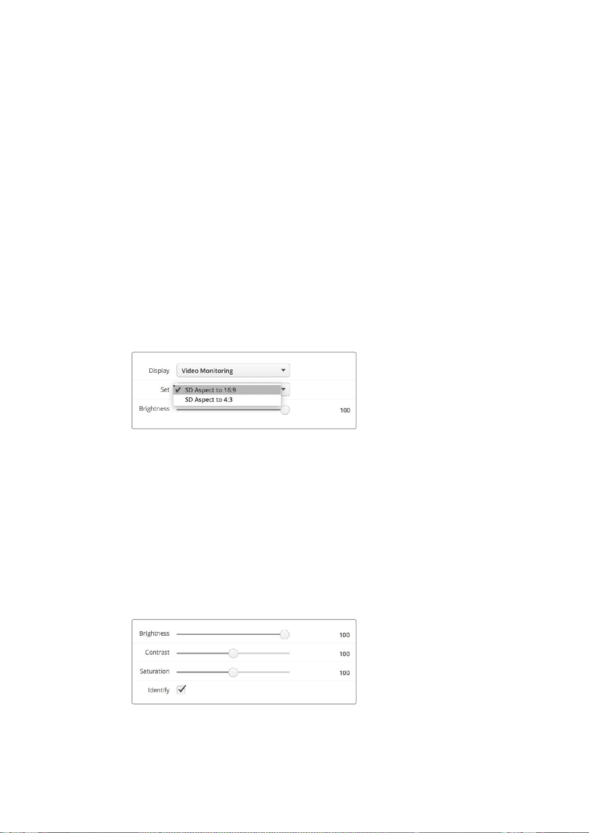
48
Blackmagic
SmartView
Setup
の使用
Display(ディスプレイ)
SmartScope
を使用する場合は「
Display
(ディスプレイ)」ドロップダウンメニューに、スコープのオプション
が表示されます。ビデオの映像を表示したい場合は「
Video
Monitoring
(ビデオモニタリング)」を選択
します。
Set(設定)
SmartScope
を使用する場合は「
Set
(設定)」ドロップダウンメニューで、
SD
ビデオモニタリングのアスペ
クトレシオを
4:3
または
16:9
から選択できます。「
Set
」には、選択したモニター用のオプションとしてベクト
ルスコープ、オーディオの
dBFS
、
dBVU
が 表示されます。
Video
Monitoring
(ビデオモニタリング):
ビデオ映像のアスペクトレシオを
4:3
または
16:9
から選 択します。
ワイドスクリーンのアナ モルフィック
SD
ビデオの表示には
16:9
を選択します。従来型の
4:3
の
SD
ビデオの表示には
4:3
を選 択します。
Vectorscope
(ベクトルスコープ):
入力に使用されているカラーバーテスト信号に応じ
て、
100%
または
75%
から選択します。
Audio
dBFS
(オーディオ
dBFS
):
位相をモニタリングするオーディオチャ
ンネル を選 択します。
Audio
dBVU
(オーディオ
dBVU
):
位相をモニタリングするオーディオチャ
ンネル を選 択します。
アナモルフィック
SD
ビデオの表示には「
SD
Aspect
to
16:9
(
SD
アスペクトレシオ
16:9
)」を選択します。
Brightness、Contrast、Saturation
スライダーを使用して明るさ、コントラスト、サチュレーション設定を調整します。
Identify(モニターの特定)
「
Identify
」にチェックが入っていると、
Blackmagic
SmartView
Setup
で選択されているモニターに白い
線が表示されます。ネットワークで複数の
SmartView
や
SmartScope
を使用している際に、この設定を使
用すると、選択されているモニターを簡単に確認できます。
「
Both
Monitors
(両方)」に設定している状態で、この設定を使用すると、白い線は
SmartView
Duo/
SmartScope
Duo
4K
の両方のモニターに表 示されます。
スライダーを動かして、明るさ、コントラスト、サチュレーションを
調整します。「
Identify
」にチェックを入れると、選択しているモニター
を視覚的に確認できます。
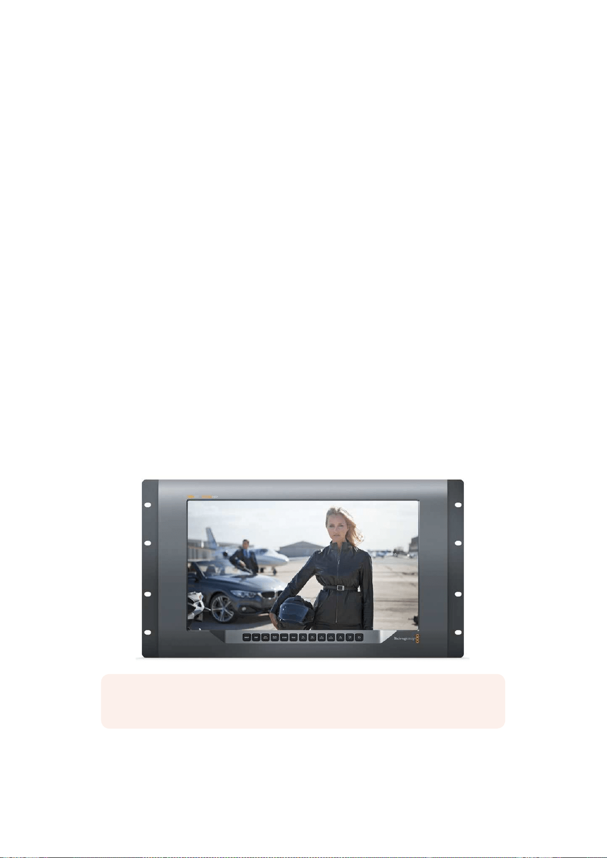
49
SmartView
4K
の使用
SmartView
4K
の使用
Blackmagic
SmartView
4K
について
SmartView
4K
は
6U
ラックサイズの
Ultra
HD
12G-SDI
放 送モニターで、
SD/HD
に加え、
2160p60
までの
Ultra
HD
ビデオをネイティブで表示できます。広視野角の高輝度ディスプレイを搭載した
SmartView
4K
の鮮明で極めてクリアな映像を使って、フォーカス合わせやカラーのモニタリングが可能。また、事実上
すべてのビデオフォーマットをサポートしています。
スタジオ放送や野外放送での使用を意図してデザインされているため、
SmartView
4K
の使用方法は非常
に簡単です。筐体の側面に配置されたコネクターと、
VESA
マウントを使用すると、狭い場所への設置、ウ
ォールマウント、連結式アームへの取り付けができます。
SmartView
4K
は内蔵のフロントパネルで操作で
きま すが、フロントパネル にアクセスで きな い 場 合 はイー サネットでリモ ートコントロール も可 能 です。
2
系統のマルチレート
12G-SDI
入 力を搭 載しているため、
2
つの
SDI
ソースから選択できます。また、
SMPTE
準拠
SFP
モジュール用ソケットを搭載しており、光ファイバー
SDI
モジュールを追 加して光ファイバーでビ
デオを接続することも可能です。
1
系統の
12G-SDI
出力からは、ビデオを他の機器にフィードできます。ま
た、ネットワーク接続およびリモートコントロール用の
2
つの イーサネットコネクター 、他の モニターとの
デイジーチェーン接 続 用のループ出力も搭 載しています。他にも、ライブプロダクション用タリー入 力、内
部ソフトウェアのアップデート用
USB
ポートを搭載しています。
加えて、
Blackmagic
SmartView
Setup
ソフトウェアを使って、業界標準の
3D
LUT
を
.cube
拡張子でロー
ド、または
DaVinci
Resolve
が生成した
LUT
を読み込むこともできます。
3D
LUT
を使用すると、
SmartView
4K
を直接カメラに接続し、最終的なグレーディングを適用したイメージに最も近い形でクリップを表示
できます。フォーカスピーキングは
2
レベルあり、ショットのフォーカスが完璧に合っているか確認できま
す。
AC/DC
電源の両方が利用可能なため、
SmartView
4K
を主電源に接続しても、セットで移動しやすい
外部バッテリーに接続しても使用できます。
SmartView
4K
は、ポータブルかつスタジオでの制作に最適な放送用モニターで、
SD/HD
ビデオに加え、
ネイティブ解像度
3840x2160
ピクセルの
Ultra
HD
に対応しています。
メモ
DC
電源入力に外部電源を接続している場合、必ず
12V
で
24W
の電源供給を行える外部電
源 を 使 用してください 。
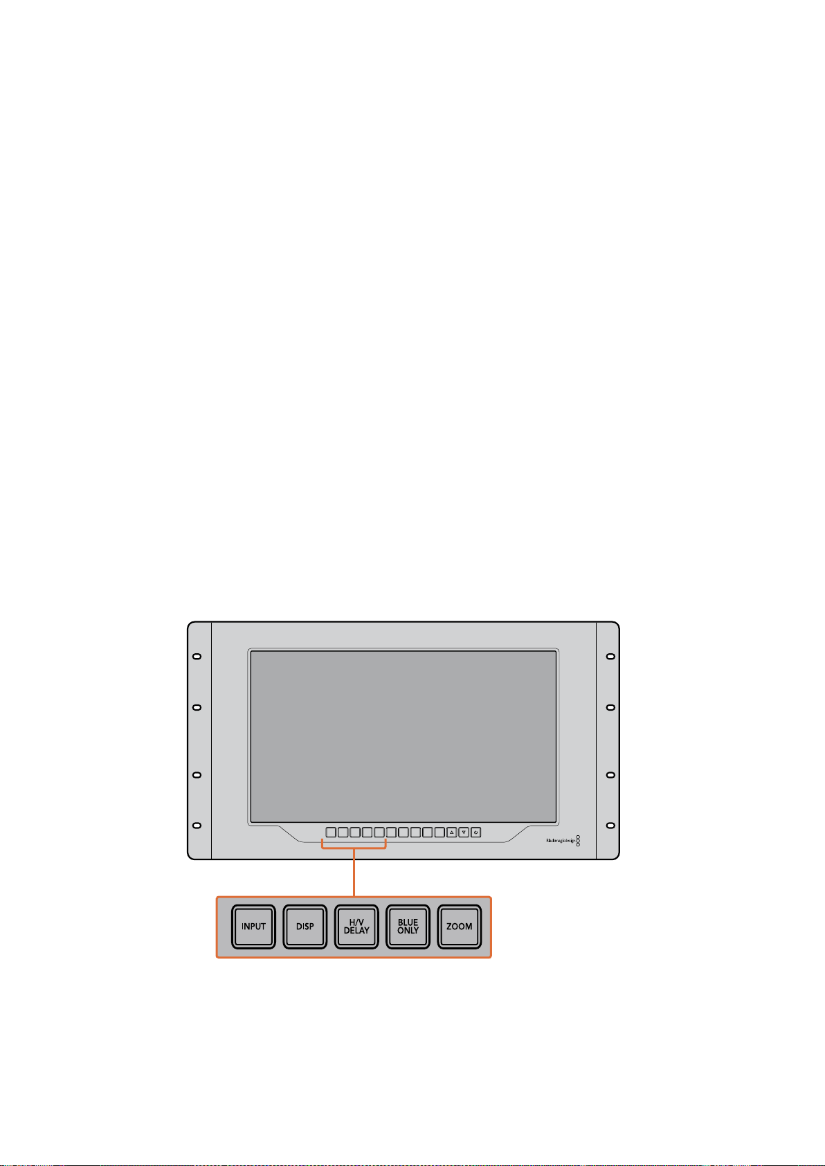
50
SmartView
4K
の使用
コントロールパネルボタン
コントロールパネルには複数のボタンが搭載されており、
SmartView
4K
の設定を瞬時に調整できます。
INPUT(入力)
SmartView
4K
の
2
系統の
12G-SDI
入力、およびオプションの光ファイバー
SFP
モジュール入力に接続され
ているビデオ信号を切り替えます。入力にビデオが接続されていない場合、
SmartView
4K
は該当の入力
にブラックを表示します。入力を切り替えると、入力のフォーマット情報がモニターの上部左端に一瞬、
表示されます。
DISP(ディスプレイ)
SmartView
4K
の
LCD
の明るさを調整します。上下の矢印ボタンを押して、明るさを調整します。「
DISP
」
ボタンを再度押して、設定を閉じます。
H
/
VDELAY(H
/
Vディレイ)
SDI
ビデオ信号にエンベッドされている補助データを確認できます。例えば、「
H/V
DELAY
」ボタンを
1
回
押すと水平方向の補助データが表示されます。同ボタンを再度押すと、縦方向の補助データが表示され
ます。これは一般的にクローズドキャプションに使 用されています。
BLUEO NLY(ブルーオンリー)
デジタルビデオ信号にノイズがある場合、ブルーチャンネルで最も際立って表示されます。「
BLUE
ONLY
」
ボタンを押すと、ブルーチャンネルでノイズを簡単にチェックできます。これは、ブルーチャンネルのみを
表示する白黒のイメージです。この白黒のイメージをカメラのフォーカス確認のために使用すること
もできます。
ZOOM(ズーム)
クリアなフォーカスを得るために使用します。
1
回押すとイメージにズームします。これにより、フォーカス
が合っているか、はっきりと確認できます。再度「
ZOOM
」ボタンを押すと通常の表示サイズに戻ります。
INPUT DISP
H/V
DELAY
3D
LUT 1
BLUE
ONLY
ZOOM PEAK
3D
LUT 2
H
MARK
V
MARK
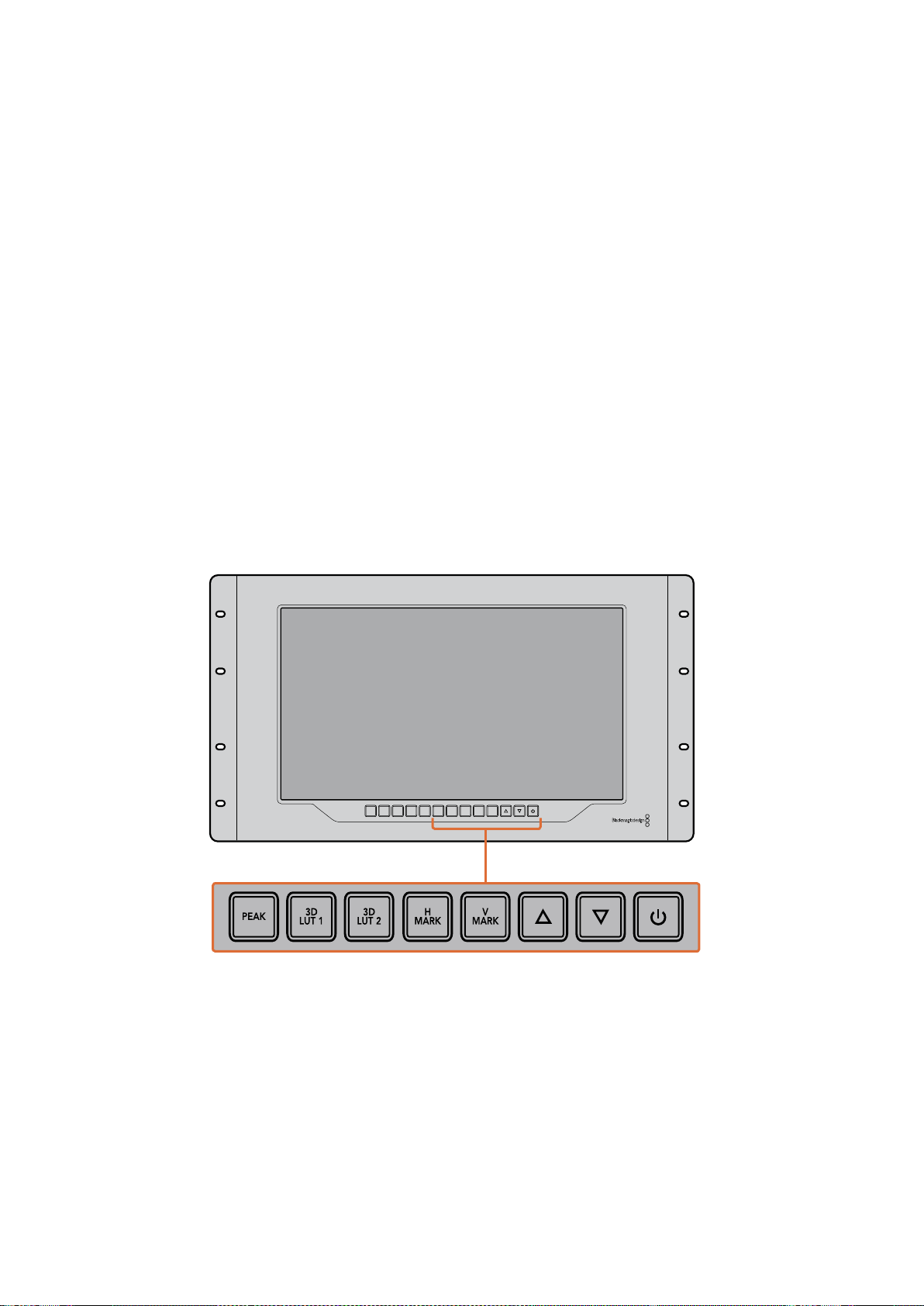
51
SmartView
4K
の使用
PEAK(ピーク)
フォーカスピーキングを有効にして、カメラのフォーカスを簡単にチェックできます。これは、イメージの
最もシャープな部分を緑色で縁取りします。ピーキングの強度は
2
レベルあり、「
PEAK
」ボタンを押して
切り替えます。緑 のエッジが 最も強い部分に、カメラのフォーカスが合っています。
3DLUT1、3DLUT2
この機能を使用すると、
Blackmagic
DaVinci
Resolve
で生成 され た カスタム
3D
LUT
、または業界標準の
cube
LUT
を適用したイメージを確認できます。「
LUT
」ボタンを押して、
LUT
を有効にします。再度押す
と、
LUT
は無 効になります。
SmartView
4K
での
3D
LUT
の使用に関しては「
Blackmagic
SmartView
Setup
で
3D
LUT
をロード」のセクションを参照してください。
HMARK(横方向マーカー)、VMARK(縦方向マーカー)
「
H
MARK
」または「
V
MARK
」ボタンを 使 って フレ ームマーカ ー の確認 と 編集が行えま す。フレ ームマー
カーは、ショットの構成や、スクリーンのセーフエリア内に重要な情報やグラフィックが配置されている
か確認するために使用します。テレビの種類によって、ビデオ信号の端の表示に多少の差があるため、
セーフエ リアを確認できるのは便利な機能です 。セーフエ リアは、テレビやモニ ターの種類に関わら ず 、必
ずスクリーンに表示される領域です。
横方向のフレームマーカーの確認には「
H
MARK
」、 縦方向には「
V
MARK
」ボタンを押します。マーカー
の編集は、各ボタンを再度押して、それぞれのガイドをハイライトします。これで、上下の矢印ボタンを
使って、マーカーの位置を編集できます。各ボタンを再度押すと、新しい配置を確定します。もう一度ボタ
ンを押すとマーカーが無効になります。
上下の矢印ボタン
設 定の調 整に使 用します。例えば、ディスプレイの明るさやフレームマーカー の位 置の調 整に使 用します。
電源
電源ボタンを
1
度押すと、
SmartView
4K
の電源がオンになります。再度押すとオフになります。
INPUT DISP
H/V
DELAY
3D
LUT 1
BLUE
ONLY
ZOOM PEAK
3D
LUT 2
H
MARK
V
MARK

52
SmartView
4K
の使用
Blackmagic
SmartView
Setup
で
3D
LUT
をロード
SmartView
4K
は、ビデオに
3D
LUT
を適用してモニタリングできます。これにより、プロ仕様のキャリブ
レーション
LUT
を使 用して
SmartView
4K
のキャリブレーションを行なったり、最終的なグレーディングを
適用したイメージに最も近い形でビデオを表示できます。また、
3D
LUT
を使用して異なるルックを試す
こともできます。
LUT
は、
Blackmagic
SmartView
Setup
で
SmartView
4K
に読み込み可能で、業界標準の
LUT
ファイルを
.cube
拡張子でロードできるため、
Blackmagic
DaVinci
Resolve
が 生成した カスタム
LUT
もロードできます。
LUT
ファイルの生成についての詳細は、
DaVinci
Resolve
マニュアル を 参 照してくださ
い。
3DLUTを3DLUT1にロード:
1
Blackmagic
SmartView
Setup
を起 動します。
2
Load
LUT
1
の「
Load
」ボタンを押します。ロードする
LUT
が保存されている場所を入力するウィ
ンドウが開きます。任意の
.cube
の
LUT
ファイルを選択して「
Open
」ボタンを押します。
3
読み込んだ
LUT
を確認するには、
SmartView
4K
のコントロールパネルの「
3D
LUT
1
」ボタンを押
します。
LUT
をオフにする場合は同じボタンをもう一度押します。
3D
LUT
2
への
LUT
のロードは、上記の手順と同じです。
Blackmagic
SmartView
Setup
で
3D
LUT
を
SmartView
4K
にロード

53
SmartScope
Duo
4K
の使用
SmartScope
Duo
4K
の使用
Blackmagic
SmartScope
とは
従来、放送品質のテレビ
/
ポストプロダクション用スコープは、非常に高価なカスタム・ソリューション
だった上、小さなスクリーンで
1
度に
1
種類のスコープしか使用できませんでした。スコープによっては、見
栄
えが悪く、クライアントの前での使用に不向きなものもあります。
SmartScope
Duo
4K
は、波形モニターをモニタリングに追加でき、デュアルモニターでビデオ信号のあら
ゆるディテールをリアルタイムで確認できます。
Blackmagic
SmartView
Setup
で入力信号に変更を加え
ると、
SmartScope
Duo
4K
で直ちに確認できます。さらに、各入力信号はもう一方のモニターに
SDI
、
左側のモニターに送信されている入力信号を、右側のモニターにスコープで表示できます。
SmartScope
Duo
4K
に表示されるスコープは
Blackmagic
SmartView
Setup
ソフトウェアで 選 択します。
「
Display
」ドロップダウンメニューからスコープを選択します。
下記および次の数ページに渡って、各スコープの使用方法を紹介しているので、それぞれの使い方の理解
を深める参考にしてください。
Blackmagic
SmartView
Setup
を使用して、異なるスコープを
Blackmagic
SmartScope
Duo
4K
の 各モニター簡単に表示できます。
ビデオモニタリング表示
Video
Monitoring
(ビデオモニタリング)表示は便利かつ信頼性の高いモニターで、
SmartScope
が受信
しているビデオを確認できます。
SD
入力信号の場合「
Set
」ドロップダウンメニューで、
4:3
ピラーボックスまたは
16:9
から表示方法を選択
できます。
LCD
の明るさ、コントラスト、サチュレーションに行なった調整はすべて、この表示で直ちに確
認できます。これらの変更はモニターにのみ適用され、ビデオ信号には適用されません。スコープは、サ
チュレーションや明るさの変更による影響を受けません。
一方のモニターを「
Video
Monitoring
」に設定してビデオを表示し、もう一方でスコープを表示すると便
利な場合が多いです。これは、「
MONITOR
1
」の
SDI
OUT
(ループスルー出力)を「
MONITOR
2
」の
SDI
IN
に短いケーブルで接 続することで実行できます。
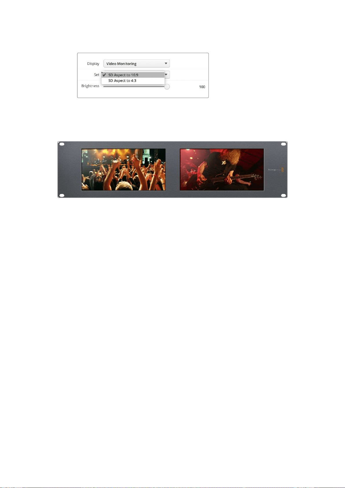
54
SmartScope
Duo
4K
の使用
SD
ビデオは、
Blackmagic
SmartView
Setup
の「
Set
」ドロップダウン
メニューで、
4:3
ピラーボックスまたは
16:9
ワイドスクリーンから
表示方法を選択できます。アナモルフィック
SD
ビデオの表示には
「
SD
aspect
to
16:9
(
SD
アスペクトレシオ
16:9
)」を選択します。
Video
Monitoring
表示は、テレビ画面やモニターに通常表示される ビデオ信号を表示する設定です。
波形表示
Waveform
(波形)表示は、従来型のルミナンス波形モニターのような、デジタルエンコードされた波形を
表示し、ビデオ信号のルマ(輝度)レベルのモニタリングおよび調整に使用します。
従来型のルミナンス波形モニターでは、
SD
のアナログ・コンポジット映像以外はサポートされていませんで
した。しかし、
SmartScope
Duo
4K
の波形表示は
HD/SD/Ultra
HD
に対応しているため、
HD
デジタルビデオ
フォーマットでモニタリングを行っている場合でも、ルマレベルを一貫した方法で簡単に調節できます。
Blackmagic
SmartView
Setup
の「
Display
」ドロップダウンメニューで 「
Waveform
(波形)」を選択します。
波形の黒レベルが
0%
未満、白レベルが
100%
を超過しないようにすることで、ルミナンス値の不正レベル
を防げます。
波形モニターはイメージをグラフ化したもので、フレーム内のルミナンス値を、位置を反映した形で表示
します。例えば、空の一部が露出過多の場合、フレームに表示されるのと同じ横方向の位置に波形が表
示されます。
フッテージによって波形の見え方は異なります。コントラストが高いビデオをモニタリングしている場合、
中間グレーに値が表示されない可能性があります。下の写真は、均等な露出の画像で、左側に暗い領域
があり、フレームの中心から右側にかけて明るい値があることが確認できます。

55
SmartScope
Duo
4K
の使用
ルミナンス値を表示する波形
Blackmagic
SmartView
Setup
の「
Display
」設定で「
Waveform
(波形)」を選択して、ビデオ信号のルミナンス値を確認します。
ベクトルスコープ表示
Vectorscope
(ベクトルスコープ)表示で は、ビデオ信号の 色をベクトルビューで 表 示します。カラーバー
テスト信号の基準に応じて、
Blackmagic
SmartView
Setup
の「
Set
」ドロップダウンメニューで、
100%
ま
たは
75%
を選択します。
ベクトルスコープを不正レベルのチェックに使用できると思っている人もいますが、それは正しくありませ
ん。不正カラーのチェ ックには、
RGB
パレード表示を使用し ます 。不正レベルのチェ ッ クにベ ク ト ル スコ
ープを使用できない理由は、不正レベルの確認にはクロマ
/
ルミナンスの両方の値をチェックする必要が
あるからです。例えば、ホワイト
/
ブラックポイントに近い色は、ルミナンスの中間グレーである色ほど彩
度を上げることはできません。ベクトルスコープ表示にはカラーのみが表示され、ルミナンス値は表示さ
れないため、単独では不正カラーのチェックには使用できません。
ベクトルスコープ表示は、クロマレベルの調節が必要な古いアナログビデオテープのカラーレベルの
チェックには最適なツールです。ビデオテープのカラーバーの部分を再生し、ビデオのカラーをグラフ内の
正方形のボックスに合わせるように、クロマおよび色相設定を調節します。
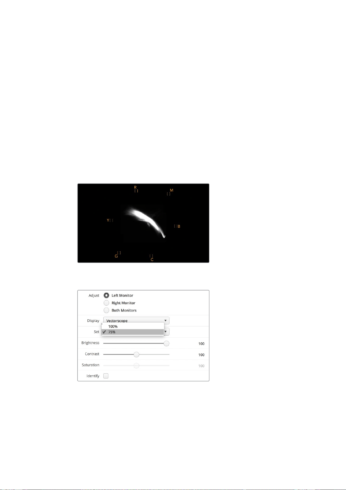
56
SmartScope
Duo
4K
の使用
ベクトルスコープ表示は、ビデオのホワイトバランスが適切か、また、色かぶりがあるかどうか簡単に確
認できるためカラーグレーディングにも最適です。ビデオに色かぶりがある場合は、ベクトルスコープ表
示が中心から外れ、中心ドットが
2
つ見える場合があります。通常、ビデオ信号のブランキングによって、
ベクトルスコープの中心にドットが生成されます。これは、ビデオのブランキングが色を含まないブラック
であるためです。ブランキングは、色情報を含まないブラックビデオの範囲を識別するのに役立ちます。
ビデオに色かぶりが生じている場合は、ブラックが中心からずれます。ずれの度合いは映像の色かぶり
の程度を表しています。映像のホワイト
/
ブラックのディテールでずれを確認できます。この機能は、ベク
トルスコープ表示で色かぶりを除去し、正しいホワイトバランスに戻すのに役立ちます。
ベクトルスコープ表示を使用すれば、誤ってブラック
/
ホワイトに不要な色かぶりを生じさせることなく、
ビデオの色を限界まで押し上げることができます。カラーバランスは
RGB
パレード表 示とベクトルスコー
プ表示の両方でモニタリングできますが、多くの場合、ベクトルスコープ表示の方がカラーバランスの問
題を簡単に確認できます。
特に顔など、肌のトーンのカラーコレクションを行う際は、ベクトルスコープの
10
時くらい の線 に 沿 うよう
にすると、温かいカラーサチュレーションを保てます。これは「フレッシュトーン・ライン」と呼ばれ、皮膚
の下にある血液の色に基づいたラインです。したがって、フレッシュトーン・ラインは、あらゆる肌の色に
適用でき、出演者の肌のトーンを自然な色に見せることができます。
10
時の線に沿 う「フ レッ シュト ーン・ラ イン」を表示す る ベ クトル ス コ ー プ
ベクトルスコープでカラーバーテスト信号を
100%
または
75%
に選択
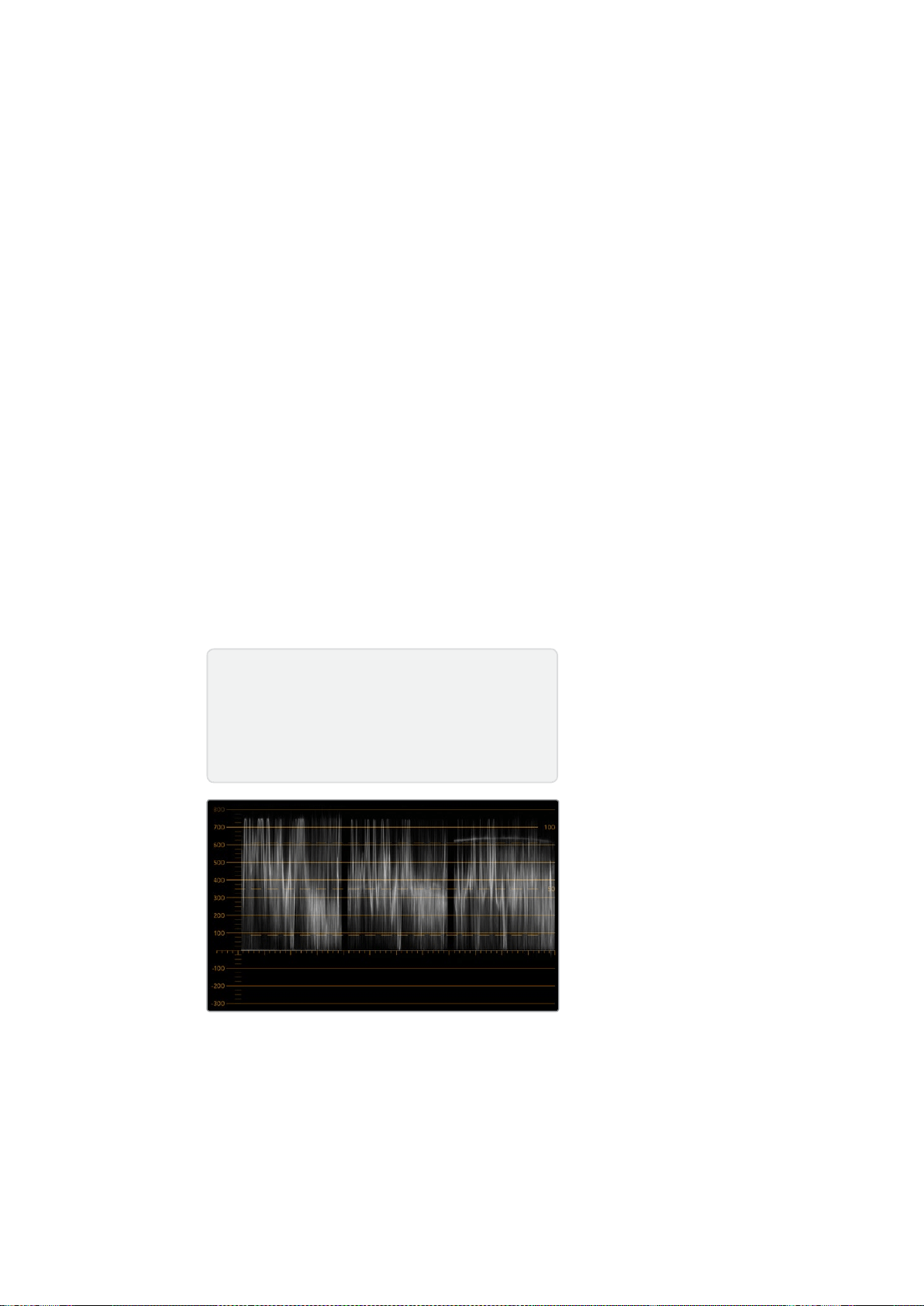
57
SmartScope
Duo
4K
の使用
パレード表示
RGB
および
YUV
パレード表示はカラーコレクション、不正カラー、レベルのチェックに最適です。
カラーコレクションを行う際は、
Blackmagic
SmartView
Setup
の「
Display
」ドロップダウンメニューで
「
RGB
Parade
(
RGB
パレード)」を選択します。
RGB
Parade
表示は、赤、緑、青の各カラーチャンネルの
全長を表示します 各カラーチャンネルのレベルをモニタリングすることで、ビデオ信号のブラック、中間、
ホワイトのカラーバランスを簡 単に確認で きます。
RGB
パレードは、赤、緑、青のチャンネルに共通のディ
テールを確認でき、カラーバランスの調整や色かぶりの除去が簡単に行えます。
カラーコレクションを行う上で、ビデオレベルをクリッピングしない範囲で最大限にすることが重要で
す。ビデオレベルを上げる場合は、
RGB
の上限を超えないように注意してください。超過すると不正レベ
ルになります。機器によっては、不正である
RGB
レベル
100%
を生成できないものもありますが、生成でき
る機 器もあります。
SmartScope
Duo
4K
では、不正レベルが生じた場合すぐに確認できます。
また、不正ビデオレベルは黒
/
白レベルでも生じます。一部のカラーコレクションシステムでは、黒レベル
は
0%
のブラックポイントを下回ることができます。不正な黒レベルが見られる場合は、「リフト」または
「ゲイン」を上げて、適切な値になるように調整します。同時に、目盛線の
100%
を確認しながら、ビデオ信
号全体が上がりすぎて、白が不正なレベルにならないように調整します。
YUV
レベルの確認は「
Display
」ドロップダウンメニューで「
YUV
Parade
(
YUV
パレード)」を選択します。
これは、ルマ(輝度)値がクロマ(色)値とは別に表示されるので、テレビ放送用のビデオ信号にとって便
利なスコープです。左にはルマの情報が表示され、中央と右はクロマの情報が表示されます。
YUV
パレー
ドは、ビデオ信号のクロマ値をカラーバーのテストパターンにを使ってキャリブレーションする際に便利
なスコープです。これにより、カラーが的確に表現され、 放送される信号がテレビで表示可能か確認で
きます。
カラーコレクションは、不正レベルを生じさせずに最も美しいルックの得るために調整を繰り返す作業です。
RGB
パレード
カラーコレクション用語
ブラック
/
黒
–
ビデオ信号の黒レベル
ミッド
/
中間
–
ビデオ信号の中間グレーのレベル
ホワイト
/
白
–
ビデオ信号の白レベル
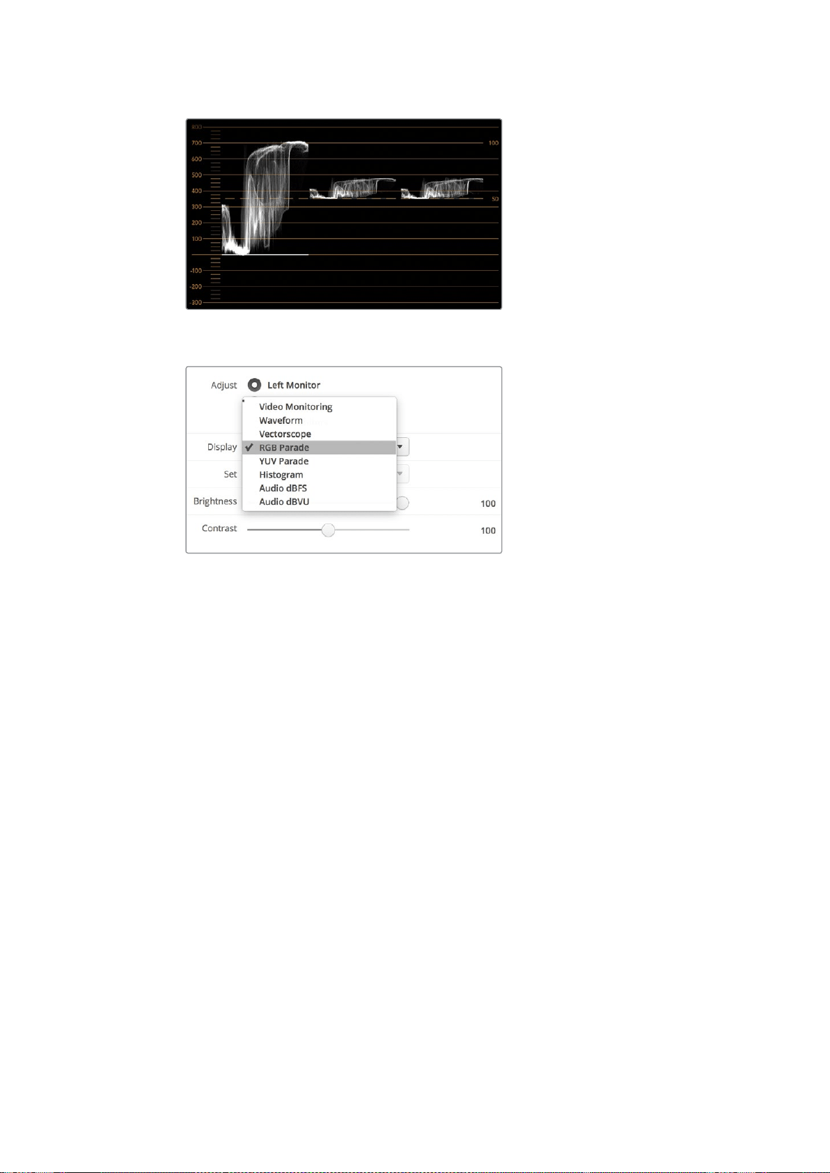
58
SmartScope
Duo
4K
の使用
YUV
パレード
Blackmagic
SmartView
Setup
の「
Display
」ドロップダウン
メニューで「
RGB
Parade
(
RGB
パレード)」と「
YUV
Parade
(
YUV
パレード)」を切り替えます。
ヒストグラム表示
Histogram
(ヒストグラム)表示は、多くのグラフィックデザイナーやカメラマンにとって馴染みのあるス
コープです。ヒストグラム表示では、白から黒までの配分情報が表示され、映像内のクリッピングされて
いるホワイト
/
ブラックのディテールが詳細に確認できます。また、ヒストグラム表示ではビデオのガンマ
変 更の 効果 が確認できます。
ブラックビデオはディスプレイの左側に表示され、ホワイトは右側に表示されます。通常、ビデオはすべ
てヒストグラム表示の
0
%から
100
%の間に表示されます。ビデオが
0%
未満や
100%
を超える場合、そのビ
デオはクリッピングされています。撮影時に生じるビデオのクリッピングは非常に悪い結果につながりか
ねません。これは、後に管理された環境でカラーコレクションを行う場合、ブラック
/
ホワイトのディテー
ルを必ず維持しておく必要があるためです。撮影時にビデオを黒および白のしきい値内に保つようにする
ことで、白飛びや黒つぶれ、ディテールの損失などを避け、後の作業で自由にカラーコレクションを行え
ます。
カラーコレクションを施す際、ビデオをクリッピングさせたい場合があるかもしれません。その場合、ヒ
ストグラム表示には、ビデオクリッピングの結果およびクリッピングされている範囲が表示されます。ま
たは、ガンマを使用することで、ディテールを保ったまま、少ないクリッピングで同様のルックが
作成できます。
ヒストグラム表示では、不正な黒
/
白レベルの確認はできますが、不正カラーレベルのチェックはできま
せん。ヒストグラム表示は色を表示しないため、ビデオに不正カラーが含まれていても、規定の範囲内の
色として表示される場合があります。不正レベルとカラーのチェックには、ビデオ信号の色とルミナンス
を両方表示する
RGB
パレード表示が最適です。

59
SmartScope
Duo
4K
の使用
ホワイトからブラックの配分を表示するヒストグラム表示
Blackmagic
SmartView
Setup
の「
Display
」ドロップダウンメニューで
「
Histogram
(ヒストグラム)」を選択します。
オーディオメーター表示
オーディオメーター表示は、
SDI
ビデオ信号のエンベデッドオーディオのオーディオレベルを表示します。最
大
16
チャンネルの エンベデッド オー ディオ が デエ ンベッドさ れ、
dBVU
または
dBFS
フォ ーマットで表示 さ れ
ます。
VU
メーターは、信号の平均レベルを表示し、従来型の機器で非常に多く使用されている、使いやすいメー
ターです。
VU
は、
SMPTE
の推奨する
1
kHz/-20
dBFS
テストトーン 信号 にキャリブレ ーションされていま す。
dBFS
は、基 本的にはデジタルオーディオ信号全般のメーターで、近代的なデジタル機器に一般的に使 用
されています。
右のオーディオスコープでは
2
チャンネル のオー ディオをモニタリング で き、チャンネル の選 択は「
Set
」ド
ロップダウンメニューで行います。例えば、チャンネル
1
と
2
、チャンネル
3
と
4
。オーディオスコープにはオー
ディオが
X-Y
ビューで表示されるため、オーディオバランスの問題、位相のずれ、またはオーディオがモノ
ラルかステレオか確認できます。モノラルオーディオは「
In
Phase
」のライン上に
1
本の縦の線で表示されま
す。線が水平方向に表示される場合は、オーディオの「位相がずれて」おり、ダウンストリーム機器に送ら
れた際に無効(例:オーディオの損失など)になる場合があります。ケーブル類が正しく接続されていない
場合のある大規模な施設などでは、位相のずれは最も多く見られるオーディオ不具合のひとつです。

60
ネットワ ー クに 接続
ステレオ信号をモニタリングしている場合、右のオーディオスコープのオーディオ信号の広がりは、左右
のオーディオチャンネルの差異を示します。オーディオトラックに含まれるステレオサウンドが多いほど、
オーディオ信号を示すラインは円形に広がっていきます。オーディオに含まれるステレオサウンドが少な
い場合は、ディスプレイの表示はより垂直軸に集中します。
会話のオーディオは垂直線のように表示されることが多い一方、ステレオサウンドを多く含む音楽のスコー
プは広がって表示されます。これは、モノラルオーディオでは
L
と
R
が同一であるため垂直軸上に表示される
一方で、ステレオでは
L
と
R
が異なり、水平軸上に
LR
の差異を示す形で表示されるためです。
ピークレベルとオーディオバランスを表示するオーディオメーター表示
「
Set
」ドロップダウンメニューからモニタリングする
オー ディオチャンネルを選 択
ネットワークに接続
SmartView/SmartScope
モニターをネットワー クに 接 続 すると、複数のユ ニットの モニター 設 定をリモ ー
トで調整できま す。
SmartView/SmartScope
モニターは、コンフィギュレーションを行わずにビデオを表示できますが、すべ
ての ネットワー ク設定 を配 置 前に設定 する 必 要が あります。ネットワークのコンフィギュレーションは 、コ
ンピューターに直接
USB
で接続されている際のみ実行できます。
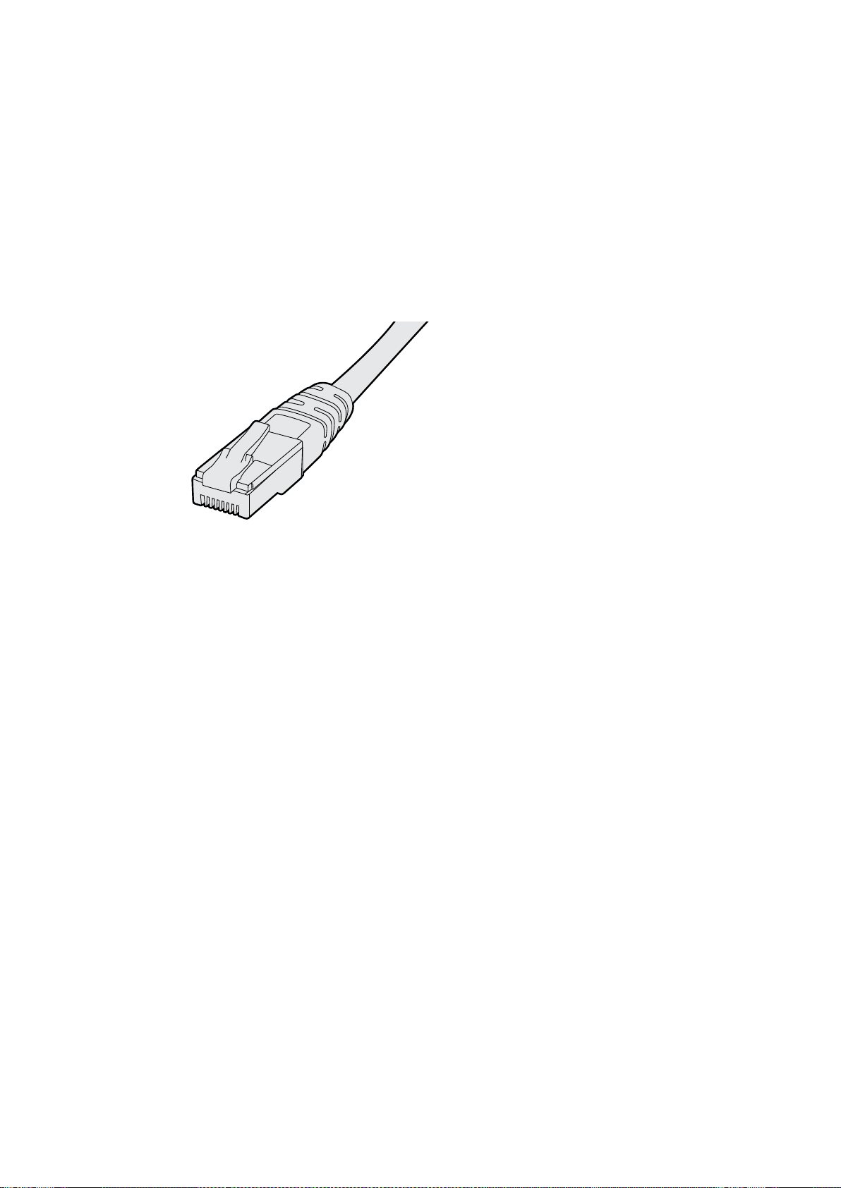
61
ネットワ ー クに 接続
ダイレクト・イーサネット
リモートでのモニタリングには、コンピューターに直接イーサネットでモニターを接続して行う方法があり
ます。この 方 法で はネットワー クスイッチ は 必 要ないため 、急いで インストールとセットアップ を 行う際 に
便 利 です。ユ ニットを 追加 するには 、各ユ ニットのアクティブ なイーサネットのル ープス ル ーを 介して、デ
イジーチェーン で 接 続しま す。この 際 、チェーン上の 全ユ ニットに 電 源 が 供給 されてい る 必 要が あります。
スタジオの既 存 のネットワー クの
IP
アドレスを使 わず に複 数のユ ニットを接 続したい 場合 や、ネットワー
ク自体がない場合、コンピューターのイーサネットポートに直接接続するだけで使用できます。この方法
では、ネットワークスイッチにケーブルを配線する必要がないため、
SmartView/SmartScope
をすばやく
イーサネットを 介して 接 続 で きます。
イーサネットコネクター
イーサネット・ネットワークスイッチ
複数 のユ ニットをスタジ オの ネットワー クに 接 続 する 場合 、ネットワ ークスイッチに
SmartView/SmartScope
を
1
台 接 続 するだけ で、残りの ユニットは各ユ ニットのアクティブ なイーサネットのル ープ スル ー を介して、
デイジーチェーンで接続できるため、スイッチのポートを複数使用する必要はありません。これにより、
ネットワークスイッチに複数のケーブルを配線する必要がありません。その際、デイジーチェーン上の全
ユニットに電源が供給されている必要があります。
ネットワー クスイッチに接 続 すると、ネットワー ク上のあらゆるコンピュー ターからユニットの 設 定 を変 更
できます。また、ネットワークにワイヤレスアクセスポイントがある場合、あらゆる
Mac
または
Windows
ラップトップから
WiFi
接 続で設 定を変 更できます。
IP
ベースの ネットワークのローカルエリアへの
SmartView/SmartScope
の接続は、下記の手順に従って
ください。
1
ユニットに同梱されている電源ケーブルをしっかりと接続し、スイッチをオンにします。
2
標準
RJ45
イーサネットケーブル を 使 用して、ネットワー クスイッチ、あるいは 直 接コンピュー ター
に接続します。
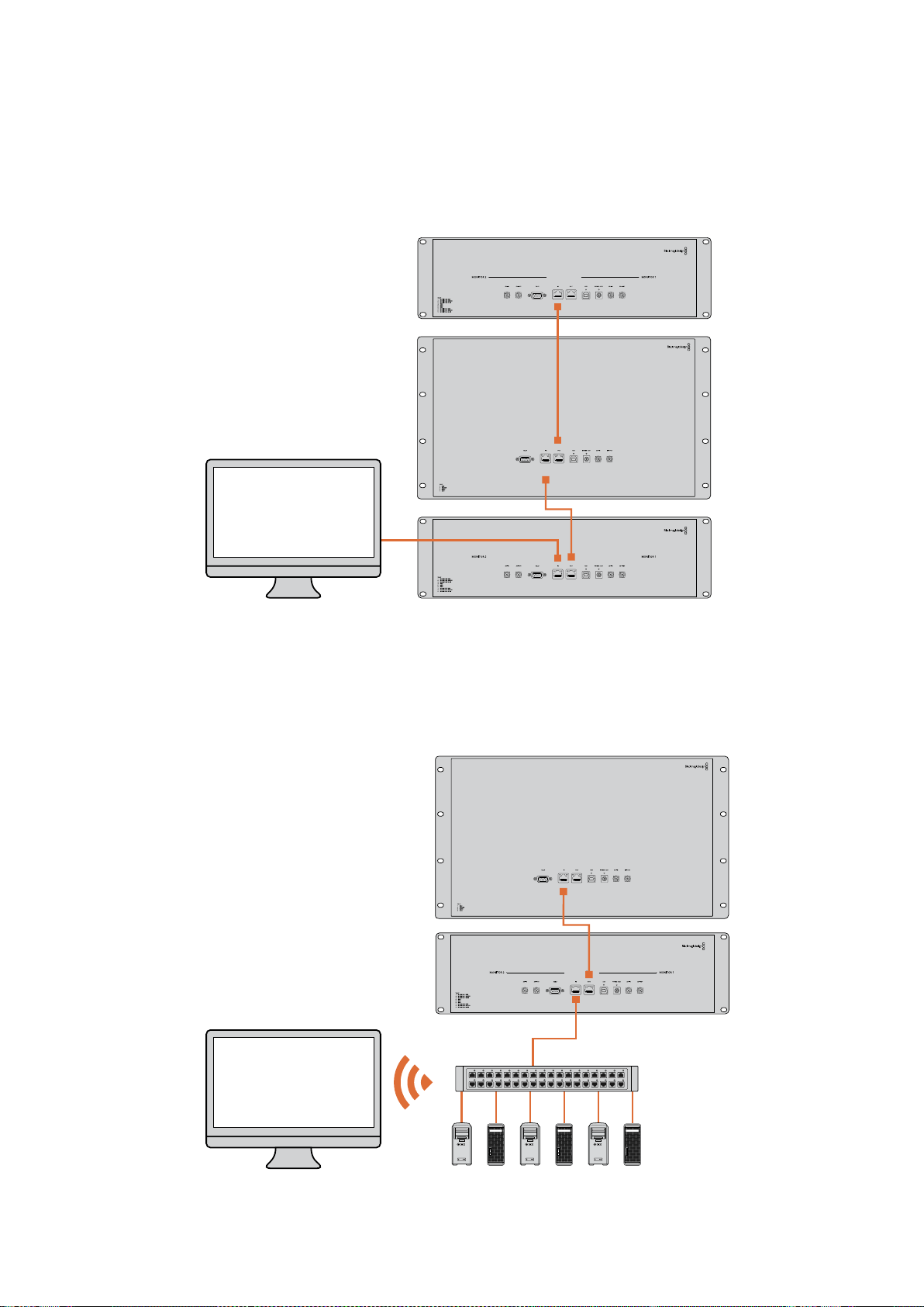
62
ネットワ ー クに 接続
ダイレクト・イーサネット接続図
ネットワー クスイッチを 使 わず に 、コンピューター のイーサネットポートに 直 接ユ ニットを 接 続 で きます。
ユ ニットはデイジー チェーン接 続 で追加 で きるため 、ネットワー クスイッチ に複数 のケーブル を配線 する
必要はありません。全ユニットに電源が供給されている必要があります。
イーサネット・ネットワークスイッチ接続図
スタジ オの既 存 の ネットワー クの
IP
アドレスを使 わず に 複 数のユ ニットを 接 続したい 場 合 、ネットワー クに
接 続 するユ ニットは
1
台だけ です。残りのユ ニットは デイジー チェーン 接 続 で 追加 できるため 、ネットワー
クスイッチに複数のケーブルを配線する必要はありません。全ユニットに電源が供給されている必要
があります。
SmartScope 4KDuo
SmartScope 4KDuo
ネットワー クスイッチ
イーサネット
クライアント
コンピューター

63
ネットワーク設定の調整
ネットワーク設定の調整
ネットワーク設定
デバイス名
各モニターに個別の名前をつけることで、ネットワークの
SmartView
や
SmartScope
を簡単に識別できま
す。(例:屋外カメラ
1&2
、マルチビュー出力、
4K
フィードなど )
モニター名を変更する場合は、必ずイーサネットまたは
USB
でモニターが接続されていることを確認して
ください。
Blackmagic
SmartView
Setup
を起動し、モニター名の下の設定アイコンをクリックします。
設定ページで「
Network
(ネットワーク)」をクリックして、「
Details
(詳細)」の欄のモニター名を編集し
ます。入力した名前が無効の場合、フィールドの横に警告アイコンが 表示されます。有効の場合、緑の
チェックマークが表示されます。コンピューターのキーボードの「
Return
」キーを押して名前の変更を
確定します。
ネットワーク設定
Blackmagic
SmartView
Setup
のネットワーク設定セクションに変更を加える場合は、
Blackmagic
モニ
ターは必ず
USB
でコンピュー ター に接続 されて いる 必 要 が あります。ネットワー ク設 定 は 、イーサネットで
は調整できません。
デ フォルトで は、
SmartView/SmartScope
は
DHCP
を使 って自動的にネットワーク から
IP
アドレスを取 得
します。
DHCP
サーバーがない場合、
macOS
の「
Internet
Sharing
」機能、
Windows
8.1
または
10
の「
Internet
Connection
Sharing
(
ICS
)」機能を有効にし、直接接続しているユニットが
DHCP
アドレスを受 信できる
ようにします。これにより、マニュアルで固定
IP
アドレスを割り当てる必要がありません。この機能を使う
と、コンピューターがインターネットに接続されていない場合でも
DHCP
アドレスを受信できることがあ
ります。インターネットシェアリングの詳細は、
macOS
または
Windows
8.1
および
10
のマニュアルなどを参
照してください 。
使用しているコンフィギュレーションで
DHCP
が使えない場合、「
Static
IP
(固定
IP
)」を選択してアドレス
を割り当てます。ネットワークで
IP
アドレスの競合を防ぐために、システム管理者にスペアの
IP
アドレスを
確認してください。各
SmartView/SmartScope
には独自の
IP
アドレスを使用し、共通のサブネットマスクを
指定する必要があります。インターネットルーターなどのネットワークゲートウェイに接続する予定がな
ければ「
Gateway
(ゲートウェイ)」のデフォルト値を変える必要はありません。
ネットワー クで
SmartView
や
SmartScope
が検出されない場合、
DHCP
経由で
IP
アドレスを受 信していな
い可能性があるため、各ユニットに適切なネットワーク設定をマニュアルで設定する必要があります。
1
コンピューターと
Blackmagic
SmartView/SmartScope
を
USB
で接続し、
Blackmagic
SmartView
Setup
ソフトウェアを起 動します。
2
接続されたモニターは自動的に
SmartView
Setup
のホームページを表示し、モニター名の隣に
USB
のアイコンを表示します。
3
モニターのネットワーク設定を調整します。
4
DHCP
経由で
IP
アドレスを受信していないユニットすべてに上記の手順で設定を行います。
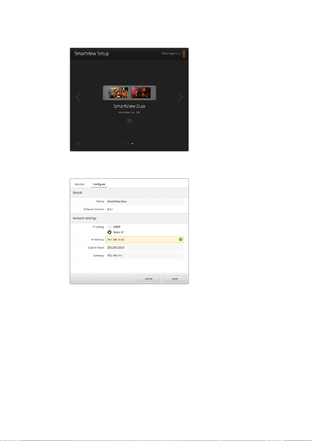
64
ネットワーク設定の調整
モニター名の隣の
USB
アイコンは、モニターが
USB
でコンピューター
に接続されていることを示します。ネットワーク設定を調整する際
は、
Blackmagic
モニターは
USB
接続されている必要があります。
ネットワーク設定 は
DHCP
または固定
IP
アドレスのいずれでも
設定でき、
USB
経由でのみ変更可能。
Blackmagic
モニターの追加
SmartView/SmartScope
Duo
4K
の
IP
アド レスが既に分かって い て 、
Blackmagic
SmartView
Setup
のホー
ムページに自動的に表示されない場合、モニターをマニュアルで追加できます。
マニュアルでの モ ニター 追加:
1
必ずイーサネットで
Blackmagic
モニターが接続されていることを確認してください。左下の
「
+
(プラス)」をクリックすると「
Add
a
[Blackmagic
モニターのモデル名
]
」ウィンドウが開きます。
2
IP
アドレスを入力し、「
Add
(追加)」をクリックします。
3
ソフトウェアがユニットの有無を検証し、
SmartView
Setup
のホームページに
Blackmagic
モニタ
ーが追加されます。右矢印のアイコンをクリックして、新しいモニターが追加されたことを確認
します。
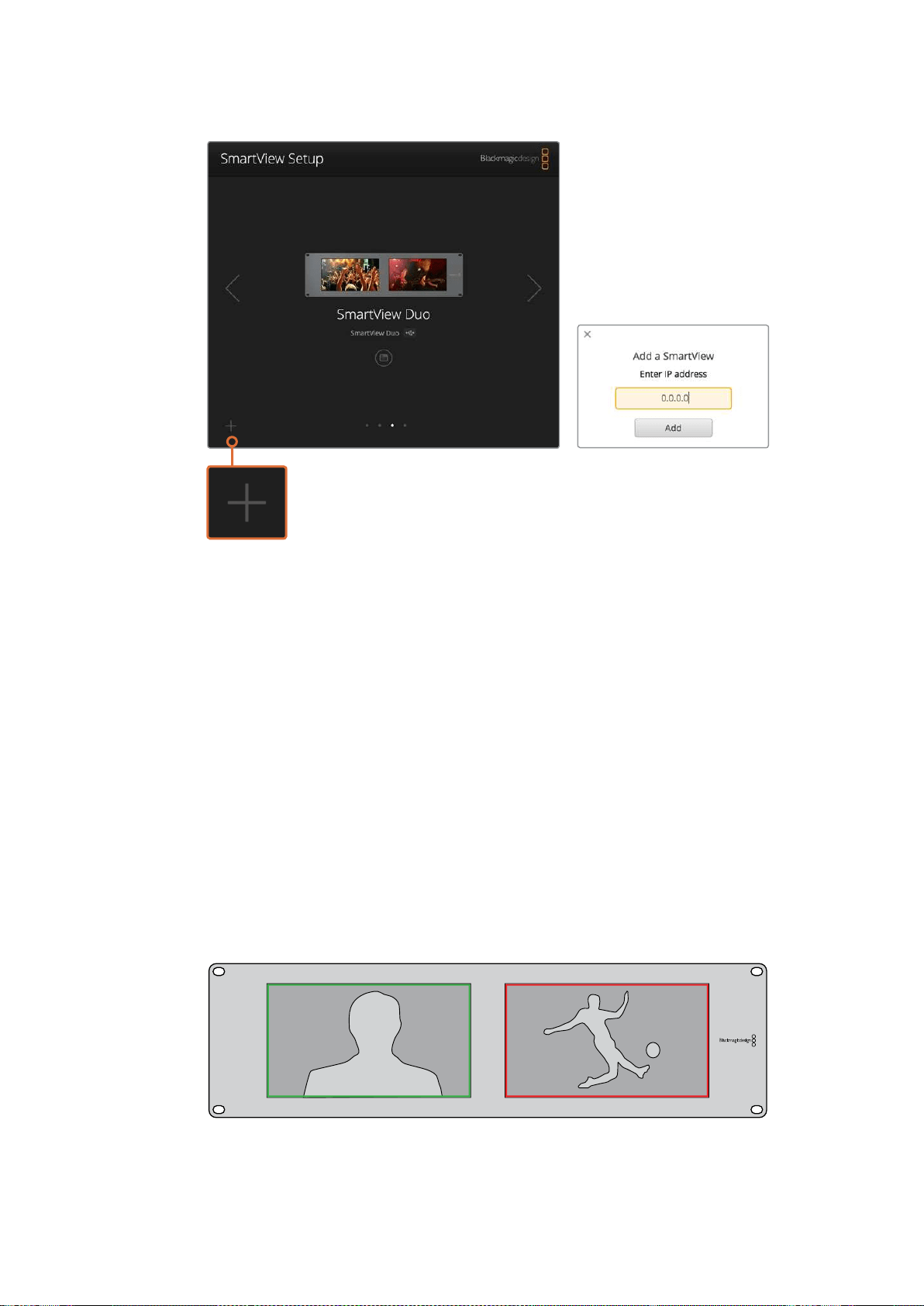
65
タリーの使 用
SmartView/SmartScope
は「
+
」アイコンをクリックするか、
IP
アドレスを入 力してマニュアルで追 加可能 。
タリーの使用
タリーポートのピン接続
SmartView/SmartScope
のタリーは必ずしも使用する必要はありません。将来的にタリーを使用する予
定がなければ、このセクションを読む必要はありません。
各
SmartView
や
SmartScope
はタリーボーダーを赤、緑、青で表示できる機能を搭載しているため、
オンエア、プレビュー、収録などのビデオ信号のステータスのインジケーターとして使用できます。
9
ピン
D
サブポートは、スイッチャーやオートメーションシステムからのコンタクト・クロージャー信号に
対応しています。スイッチャーやオートメーションシステムと併用する際のタリーポートの配線に関しては
下記のタリーのピン接続の表を参照してください。
9
ピン
D
ポートの配線に関する情報は、ユニットの背面に印刷されています。個別のモニターで赤、緑、青の
タリーボーダーを表示するコンタクト・クロージャーが記載されています。
緑と赤のボーダーを表示している
SmartView
Duo
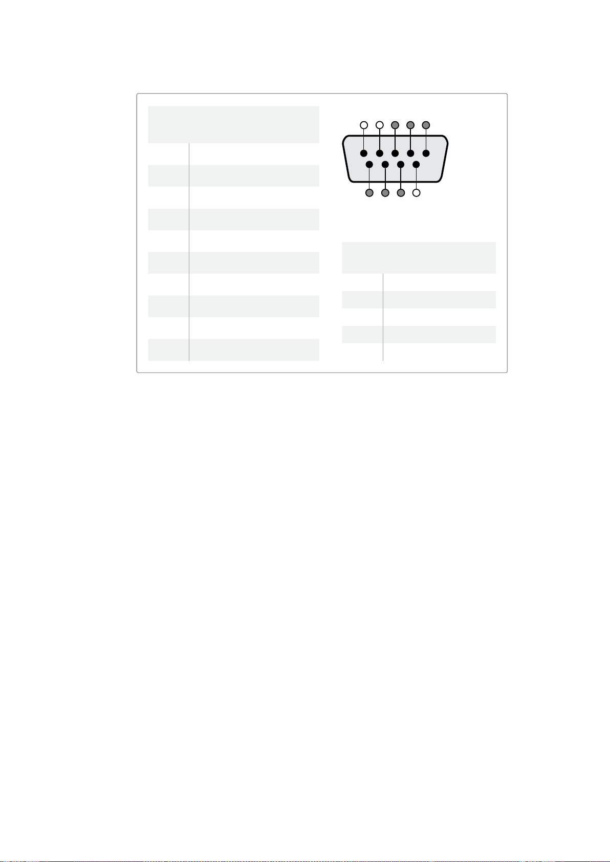
66
ビューアングルの最適化
ビューアングルの最適化
SmartView
Duo
、
SmartView
HD
、
SmartScope
を機材ラックの高い位置に設置する場合、最適なビュー
アングルを得るために
LCD
の向きを物 理的に変えることができます。
LCD
のイメージは、向きが変わった
ことを検知した場合に自動で適切な方向に変わります。背面アッセンブリーからフェースプレートを取り
外し、取り付けるためにポジドライブの
No.2
が必要です。これはシンプルな作業で背面アッセンブリーを
開ける必要はありません。
下記の手順に従って、フェースプレートの
Blackmagic
Design
のロゴを正しい向きに保ったまま、ユニット
の向きを変えます。ポジドライブの
No.2
が必 要です。
1
フェースプレートの上下左右からネジを外します。
SmartView
Duo
および
SmartScope
Duo
4K
には
10
個のネジ、
SmartView
HD
には
18
個のネジがあります。
2
図のように背面アッセンブリーからフェースプレートを取り外します。
3
背面アッセンブリーを逆向きにします。
4
逆向きにした背面アッセンブリーをフェースプレートに戻します。
5
筐体にネジで 固定します。
SmartView/SmartScope
をラックの高い位置に取り付ける準備ができました。ラックにボルト付けされた
ら、ぶつかっても調整がずれたり、外れたりする外部ノブや調整部品がないため、
SmartView
のビューア
ングルは最 適な状 態が 保たれます。
SmartViewDuo、SmartScopeDuo4K
タリーのピン接続
ピン機能
1 モニター1、レッド
2 モニター1、グリーン
3 モニター1、ブルー
4
グラウンド
5
グラウンド
6
グラウンド
7 モニター2、レッド
8 モニター2、グリーン
9 モニター2、ブルー
SmartViewHD、SmartView4K
タリーのピン接続
ピン機能
1
レッド
2
グリーン
3
ブルー
4
グラウンド
5 4 3 2 1
9
8
7 6
SmartView
タリーポート
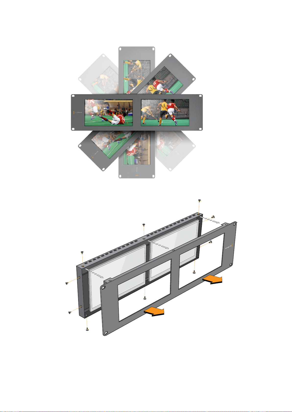

68
デベロッパーの皆様へ
デベロッパーの皆様へ
DevelopingCustomSoftwareUsingBlackmagicDesignHardware
The
Blackmagic
SmartView
Ethernet
Protocol
allows
developers
to
remotely
control
Blackmagic
SmartView
and
SmartScope
hardware
with
their
own
custom
software.
The
Blackmagic
SmartView
Ethernet
Protocol
is
a
text-based
status
and
control
protocol.
DownloadingtheFreeSmartViewEthernet
Protocol
The
Blackmagic
SmartView
Ethernet
Protocol
is
free.
It
is
included
in
this
SmartView
&
SmartScope
manual
and
can
be
downloaded
from
www.blackmagicdesign.com/jp/support
JoiningtheBlackmagicDesignDeveloperList
The
Blackmagic
Developer
mailing
list
is
designed
for
technical
questions
regarding
technologies
used
by
Blackmagic
Design,
e.g.,
QuickTime,
Core
Media,
DirectShow,
codecs,
APIs,
SDKs,
etc.
The
free
mailing
list
is
a
forum
where
developers
can
discuss
ideas
and
problems
with
other
developers.
Any
subscriber
may
reply
and
the
Blackmagic
Design
engineers
may
also
respond
when
appropriate.
You
can
subscribe
to
the
mailing
list
at:
http://lists.blackmagicdesign.com/mailman/listinfo/bmd-
developer
In
some
cases,
we
might
request
a
brief
outline
of
the
software
you
are
developing
if
it
is
not
immediately
obvious
from
your
domain
name
that
your
organization
develops
video
software.
Please
don
ʼ
t
take
offence
as
we
ʼ
re
simply
trying
to
keep
the
list
free
of
spam
and
viruses
as
well
as
end-
user
customers
asking
non-development
questions,
employment
agents
or
sales
people
trying
to
promote
products
on
the
list.
The
list
is
just
for
developers.
ContactingBlackmagicDesignDeveloper
Assistance
You
can
also
contact
us
via
developer@blackmagicdesign.com
if
you
have
any
developer
related
questions
or
wish
to
ask
questions
off
the
list.
Blackmagic
2K
Format
–
Overview
Blackmagic
Design
products
support
3G-SDI
video,
which
allows
twice
the
data
rate
of
traditional
HD-SDI
video.
We
thought
it
would
be
a
really
nice
idea
to
add
2K
film
support,
via
3G-SDI
technology,
so
we
could
simplify
feature
film
workflows.
With
the
popularity
of
Blackmagic
Design
editing
systems
worldwide,
now
thousands
of
people
can
benefit
from
a
feature
film
workflow
revolution.

69
デベロッパーの皆様へ
This
information
includes
everything
product
developers
need
to
know
for
building
native
2K
SDI
equipment.
Of
course,
all
Blackmagic
products
can
be
updated,
so
if
the
television
industry
adopts
an
alternative
SDI-based
film
standard,
we
can
add
support
for
that
too!
FrameStructure
Transmitted
at
23.98,
24
or
25
frames
per
second
as
a
Progressive
Segmented
Frame.
Active
video
is
2048
pixels
wide
by
1556
lines
deep.
Total
lines
per
frame
:
1650
Active
words
per
line
are
1535.
One
word
consists
of
a
10-bit
sample
for
each
of
the
four
data
streams,
i.e.,
a
total
of
40
bits.
See
the
diagram
named
Blackmagic
2K
Format
-
Data
Stream
Format.
Total
active
lines
:
1556
Total
words
per
line
:
1875
for
23.98/24Hz
and
1800
for
25Hz.
Fields
per
frame
:
2,
825
lines
each
Active
lines
located
on
lines
16-793
(field
1)
and
841-1618
(field
2).
TransportStructure
Based
on
SMPTE
372M
Dual
Link
mapping
and
SMPTE
425M-B
support
for
mapping
SMPTE
372M
into
a
single
3
Gb/s
link.
Timing
reference
signals,
line
number
and
line
CRC
insertion
is
the
same
as
above.
During
active
video,
10-bit
Red,
Green
and
Blue
data
is
sent
in
the
following
sequence:
Optional
ancillary
data
is
inserted
into
both
virtual
interfaces.
At
present,
only
audio
data
is
included:
as
per
standard
HD
audio
insertion
(SMPTE
S299M)
the
audio
data
packets
are
carried
on
data
stream
two
and
audio
control
packets
are
carried
on
data
stream
one.
Data
stream
1:
Green_1,
Green_2,
Green_3,
Green_5...Green_2047
Data
stream
2:
Blue_1,
Blue_2,
Green_4,
Blue_5...Green_2048.
Data
stream
3:
Red_1,
Blue_3,
Blue_4,
Red_5...Blue_2048.
Data
stream
4:
Red_2,
Red_3,
Red_4,
Red_6...Red_2048.
Blackmagic
2K
Format
–
Vertical
Timing
Reference
This
diagram
shows
the
vertical
timing
details
with
line
numbers
and
Field,
Vertical
and
Horizontal
bits
for
the
Timing
Reference
Signal
codes.
Field1 Active
F 1 0 0 0 0 0 0 0 0 0 0 0
V 1 1 1 1 1 1 0 0 0 0 1 1
LINE
#
1650 1 2
...
14 15 16
...
792 793
...
825
Field2 Active
F 0 1 1 1 1 1 1 1 1 1 1 1
V 1 1 1 1 1 1 0 0 0 0 1 1
LINE
#
825 826 827
...
839 840 841
...
1617 1618
...
1650
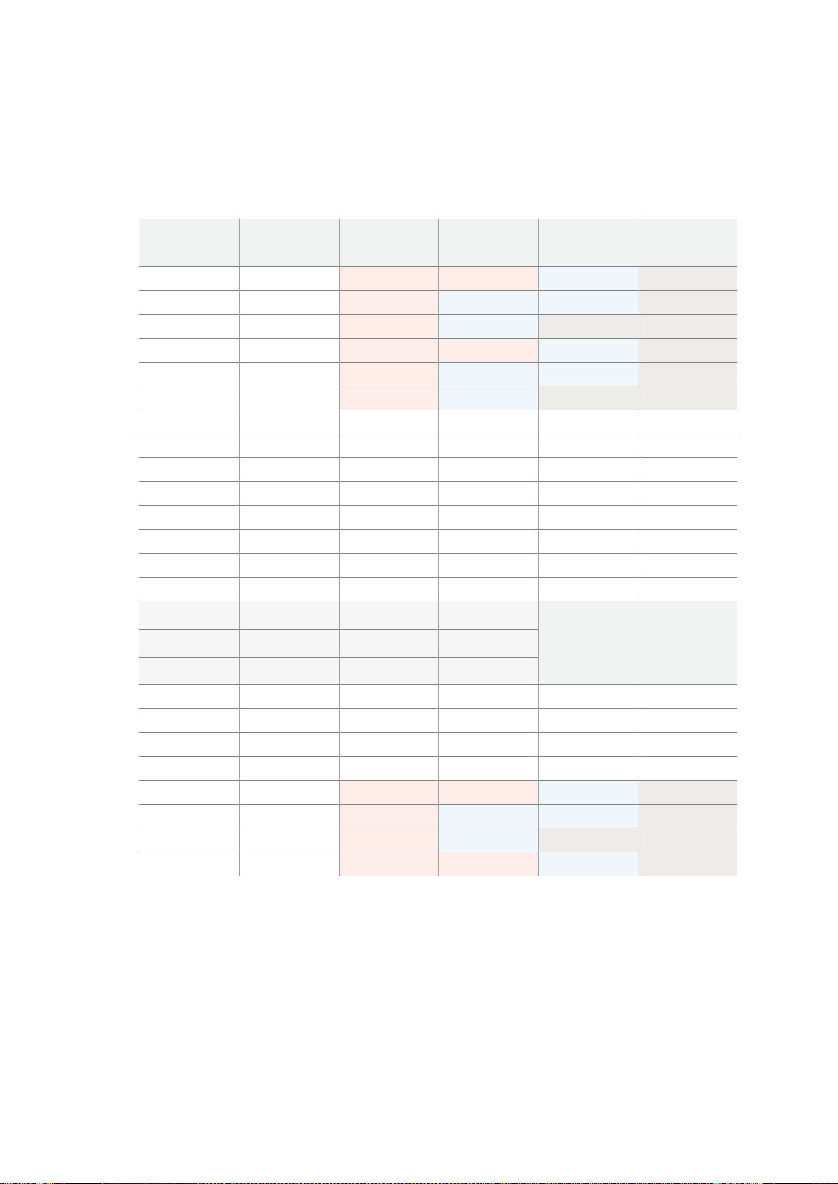
70
デベロッパーの皆様へ
Blackmagic
2K
Format
–
Data
Stream
Format
This
diagram
shows
the
data
stream
formats
around
the
optional
ancillary
data
section
of
the
horizontal
line.
Note
that
each
active
pixel
takes
up
three
samples.
Data
Stream
1
G2041
G2042
G2043
G2045
G2046
G2047
EAV
(
3FFh
)
EAV
(
000h
)
EAV
(
000h
)
EAV
(
XYZh
)
LN0
LN1
CRC0
CRC1
ANC/Audio
Data
SAV
(
3FFh
)
SAV
(
000h
)
SAV
(
000h
)
SAV
(
XYZh
)
G1
G2
G3
G5
Data
Stream
2
B2041
B2042
G2044
B2045
B2046
G2048
EAV
(
3FFh
)
EAV
(
000h
)
EAV
(
000h
)
EAV
(
XYZh
)
LN0
LN1
CRC0
CRC1
ANC/Audio
Data
SAV
(
3FFh
)
SAV
(
000h
)
SAV
(
000h
)
SAV
(
XYZh
)
B1
B2
G4
B5
Data
Stream
3
R2041
B2043
B2044
R2045
B2047
B2048
EAV
(
3FFh
)
EAV
(
000h
)
EAV
(
000h
)
EAV
(
XYZh
)
LN0
LN1
CRC0
CRC1
040
…
040
SAV
(
3FFh
)
SAV
(
000h
)
SAV
(
000h
)
SAV
(
XYZh
)
R1
B3
B4
R5
Data
Stream
4
R2042
R2043
R2044
R2046
R2047
R2048
EAV
(
3FFh
)
EAV
(
000h
)
EAV
(
000h
)
EAV
(
XYZh
)
LN0
LN1
CRC0
CRC1
200
…
200
SAV
(
3FFh
)
SAV
(
000h
)
SAV
(
000h
)
SAV
(
XYZh
)
R2
R3
R4
R6
Word#
23.98/24
PsF
1870
1871
1872
1873
1874
1875
1
2
3
4
5
6
7
8
9
…
335
336
337
338
339
340
341
342
343
Word#
25
PsF
1795
1796
1797
1798
1799
1800
1
2
3
4
5
6
7
8
9
…
260
261
262
263
264
265
266
267
268

71
デベロッパーの皆様へ
Blackmagic
SmartView
Ethernet
Protocol
v1
.
3
Summary
The
Blackmagic
SmartView
Ethernet
Protocol
is
a
text-based
status
and
control
protocol,
very
similar
in
structure
to
the
Videohub
protocol,
that
is
accessed
by
connecting
to
TCP
port
9992
on
a
SmartView
or
SmartScope
device.
Upon
connection,
the
SmartView
or
SmartScope
device
sends
a
complete
dump
of
the
state
of
the
device.
After
the
initial
dump,
state
changes
are
sent
asynchronously.
The
device
sends
information
in
blocks
which
have
an
identifying
header,
followed
by
a
colon.
A
block
can
span
multiple
lines
and
is
terminated
by
a
blank
line.
To
be
resilient
to
future
protocol
changes,
clients
should
ignore
blocks
they
do
not
recognize,
up
to
the
trailing
blank
line.
Within
recognized
blocks,
clients
should
ignore
lines
they
do
not
recognize.
Version
1.3
of
the
Blackmagic
SmartView
Ethernet
Protocol
was
released
with
SmartView
1.3
software.
ProtocolPreamble
The
first
block
sent
by
the
SmartView
Server
is
always
the
protocol
preamble:
PROTOCOL PREAMBLE:↵
Version: 1.3 ↵
↵
The
version
field
indicates
the
protocol
version.
When
the
protocol
is
changed
in
a
compatible
way,
the
minor
version
number
will
be
updated.
If
incompatible
changes
are
made,
the
major
version
number
will
be
updated.
DeviceInformation
The
next
block
contains
general
information
about
the
connected
SmartView
or
SmartScope
device.
SMARTVIEW DEVICE:↵
Model: SmartView Duo↵
Hostname: stagefront.studio.example.com↵
Name: StageFront↵
Mo nitor s: 2↵
Inverted: false↵
↵
This
example
shows
the
output
for
a
SmartView
Duo
device,
which
has
two
LCDs.
The
INVERTED
flag
indicates
whether
the
device
has
detected
that
it
has
been
mounted
in
an
inverted
configuration
to
optimize
LCD
viewing
angle.
Legend
↵ carriage return
… and so on

72
デベロッパーの皆様へ
NetworkConfiguration
The
next
block
shows
the
TCP/IP
networking
configuration:
NETWORK:↵
Dynamic IP: true↵
Static address: 192.168.2.2↵
St atic netm as k: 255.255.255.0↵
St atic gatew ay: 192.168.2.1↵
C u rr e nt ad d r e ss: 192.168.1.101↵
C u rr e nt netm a sk: 255.255.255.0↵
C u rr e nt g ate w ay: 192.168.1.1↵
↵
The
network
settings
prefixed
with
CURRENT
show
the
active
TCP/IP
settings,
and
are
read-only.
The
CURRENT
settings
reflect
either
the
DHCP
or
Static
configuration,
depending
on
the
DYNAMIC
IP
flag.
ChangingNetworkingSettings
The
network
can
be
configured
to
use
either
DHCP
or
a
static
configuration.
To
enable
DHCP:
NETWORK:↵
Dynamic IP: true↵
↵
To
set
a
fixed
IP
address,
supply
all
static
parameters,
thus:
NETWORK:↵
Dynamic IP: false↵
Static address: 192.168.2.2↵
St atic netm as k: 255.255.255.0↵
St atic gatew ay: 192.168.2.1↵
↵
The
parameters
with
the
CURRENT
prefix
are
read-only,
and
show
the
active
configuration,
regardless
of
the
static
or
dynamic
setting.
Changing
the
device
name,
or
any
network
settings,
will
cause
the
IP
connection
to
be
dropped.
The
device
will
restart
its
networking
and
advertise
its
new
name
on
the
network.
ChangingMonitorSettings
The
display
settings
for
each
monitor
are
specified
individually.
One
or
more
parameters
can
be
modified
at
the
same
time
and
multiple
settings
can
be
supplied
in
one
block.
The
valid
range
for
numeric
values
is
0-255.
The
CONTRAST
and
SATURATION
properties
are
zero-
centered,
so
the
normal
value
is
127,
such
that
the
displayed
picture
is
the
same
as
the
original.
A
value
greater
than
127
in
either
channel
will
cause
the
contrast
or
saturation
to
be
increased,
and
similarly
a
value
less
than
127
will
cause
a
decrease.
For
example,
to
set
the
brightness
to
50%
and
desaturate
the
image
to
Black
&
White:
MONITOR A:↵
Brightness: 127↵
Saturation: 0↵
↵

73
デベロッパーの皆様へ
DisplayingSDin16
:
9
The
following
command
sets
standard
definition
video
to
display
in
16:9:
MONITOR A:↵
WidescreenSD: ON↵
DisplayingSDin4
:
3
The
following
command
sets
standard
definition
video
to
display
in
4:3:
MONITOR A:↵
WidescreenSD: OFF↵
IdentificationandTallySettings
The
Identify
flag
is
transient,
and
will
cause
a
white
border
to
be
displayed
around
the
entire
picture
for
a
duration
of
15
seconds,
after
which
it
will
be
reset.
This
feature
is
primarily
aimed
at
identifying
which
monitor
is
currently
being
configured
when
it
is
mounted
in
a
rack
comprising
multiple
units.
To
turn
on:
MONITOR A:↵
Ide ntify: tr u e↵
↵
The
IDENTIFY
border
will
temporarily
override
any
other
border
setting
in
effect.
The
BORDER
property
can
be
used
to
programmatically
set
the
soft
Tally
colored
borders
to
one
of
the
primary
colors:
RED,
GREEN,
BLUE,
WHITE
or
NONE.
This
setting
can
be
overridden
by
the
electrical
Tally
signals
at
the
DB-9
input
on
the
device
itself.
For
example,
to
set
the
soft
Tally
to
green:
MONITOR B:↵
Border: green↵
↵
The
hard
wired
tally
will
always
override
the
soft
tally.
The
full
state
report
will
always
show
the
current
valid
border.
SmartScopeSettings
On
SmartScope
Duo
4K,
each
monitor
can
be
set
to
display
a
different
scope.
The
values
for
activating
specific
scopes
are
mapped
as
follows:
AudioDbfs
AudioDbvu
Histogram
ParadeRGB
ParadeYUV
Picture
(This
is
the
same
as
Video
Monitor)
Vector100
Vector75
WaveformLuma
MONITOR A:↵
ScopeMode: Picture↵
↵
In
the
example
above,
Monitor
A
has
been
set
as
a
video
monitor.

74
デベロッパーの皆様へ
DisplayingSDin16
:
9
The
set
Video
Monitor
mode
to
display
standard
definition
video
in
16:9:
MONITOR A:↵
ScopeMode: Picture↵
WidescreenSD: ON↵
DisplayingSDin4
:
3
To
set
Video
Monitor
mode
to
display
standard
definition
video
in
4:3:
MONITOR A:↵
ScopeMode: Picture↵
WidescreenSD: OFF↵
When
setting
one
of
SmartScope
Duo
4K
ʼ
s
monitors
to
audio
metering,
you
can
also
select
which
channels
to
show.
The
values
for
selecting
which
audio
channels
are
mapped
in
the
following
way:
0:
Channels
1
and
2
1:
Channels
3
and
4
2:
Channels
5
and
6
3:
Channels
7
and
8
4:
Channels
9
and
10
5:
Channels
11
and
12
6:
Channels
13
and
14
7:
Channels
15
and
16
MONITOR B:↵
ScopeMode: AudioDbvu↵
AudioChannel: 0↵
↵
In
the
example
above,
Monitor
B
has
been
selected
to
display
Audio
Metering
in
Dbvu
with
audio
channels
1
and
2
selected
for
the
phase
meter.
SelectingLUTsforSmartView4K
To
select
3D
LUTs
using
SmartView
4K:
MONITOR A:↵
LUT: 0 LUT 1
1 LUT 2
NONE DISABLE
↵
↵

75
ヘルプ
ヘルプ
ヘルプライン
サポートを得るには4つの方法があります。
1
Blackmagic
Design
サポートセンター(
www.blackmagicdesign.com/jp/support
)で、 最新のサ
ポート情報を確認する。
2
最寄りの
Blackmagic
Design
の取り扱い販売店に電話をかける。
最寄りの取扱販売店は
Blackmagic
Design
から最新の技術情報を得ているので、即座にアシス
タンスを提供できます。また、取扱販売店では個別のワークフロー要件に合わせたサポート計
画を提供できるので、それらのサポートオプションも確認することをお勧めします。
3
Blackmagic
Design
のウェブサイト、
www.blackmagicdesign.com/jp/support
で「メールを送信」
ボタンを 使 用してメールで質 問する。
4
Blackmagic
Design
サポートに電話する。サポートページの「お住まいの地域のサポートオフィ
ス」をクリックすると、最寄りの
Blackmagic
Design
サ ポ ートオ フィスが表示 さ れ ます。
ご連絡の際は、技術的な問題およびシステムの仕様を可能な限り詳しくお伝えください。できるだけ早く
お返 事いたします。
76
規制に関する警告および安全情報
規制に関する警告および安全情報
規制に関する警告
欧州連合内での電気機器および電子機器の廃棄処分
製品に記載されている記号は、当該の機器を他の廃棄物と共に処分してはならないことを示し
ています。機器を廃棄するには、必ずリサイクルのために指定の回収場所に引き渡してください。
機器の廃棄において個別回収とリサイクルが行われることで、天然資源の保護につながり、健
康と環境を守る方法でリサイクルが確実に行われるようになります。廃棄する機器のリサイクル
のための回収場所に関しては、お住いの地方自治体のリサイクル部門、または製品を購入した
販売業者にご連絡ください。
この機器は、
FCC
規定の第
15
部に準拠し、クラス
A
デジタル機器の制限に適合していることが確
認されています。これらの制限は、商用環境で機器を使用している場合に有害な干渉に対する
妥当な保護を提供することを目的としています。この機器は無線周波エネルギーを生成、使用、
放出する可能性があります。また、指示に従ってインストールおよび使用しない場合、無線通信
に有害な干渉を引き起こす恐れがあります。住宅地域で当製品を使用すると有害な干渉を引き
起こす可能性があり、その場合はユーザーが自己責任で干渉に対処する必要があります。
動作は次の
2
つを条件とします:
1
本機は、有害な干渉を起こさない。
2
本機は希望しない動作を発生しかねない干渉を含む、いかなる受信干渉も受け入れる必要
がある。
安全情報
この機器は、必ず保護接地のあるコンセントに接続してください。
感電のリスクを減らすため、水が跳ねたり、滴るような場所には置かないでください。
この機器は、周囲温度が最高
40
度までの熱帯地区での 使用に対応しています。
通気が妨げられないように、当製品の周囲は通気に十分なスペースを開けるようにしてください。
ラックマウントする場合は、隣接する機器により通気が妨げられないようにしてください。
ユーザーが保守できる部品はありません。サービスに関しては、お近くの
Blackmagic
Design
の
サービスセンターにお問い合わせください。
海抜
2000m
以上では使用しないでください。
当製品は、
SFP
(スモールフォームファクタ・トランシーバー)光ファイバーモジュールが接続可能。
レーザークラスのクラス
1
の
SFP
光モジュールを使用。
推奨される
Blackmagic
Design
SFP
モ ジュール:
3G-SDI
:
PL-4F20-311C
6G-SDI
:
PL-8F10-311C
正規サービススタッフへの注意
サービス前に、電源を電源インレットから外してください。
警告
–
二極
/
中性ヒューズ
この機器の電源供給には、電圧線と中性線の両方にヒューズが使われており、ノル
ウェーの
IT
電力 分配システムへの接続 にも適しています。

77
保証
保証
12
ヶ月限定保証
Blackmagic
Design
は、お買い上げの日から
12
ヶ月間、本製品の部品および仕上がりについて瑕疵がない
ことを保証します。この保証期間内に製品に瑕疵が見つかった場合、
Blackmagic
Design
は弊社の裁量に
おいて部品代および人件費無料で該当製品の修理、あるいは製品の交換のいずれかで対応いたします。
この保証に基づいたサービスを受ける際、お客様は必ず保証期限終了前に
Blackmagic
Design
に瑕疵を
通知し、適応する保証サービスの手続きを行ってください。お客様の責任において不良品を梱包し、
Blackmagic
Design
が指定するサポートセンターへ配送料前払で送付いただきますようお願い致します。
理由の如何を問わず、
Blackmagic
Design
への製品返送のための配送料、保険、関税、税金、その他すべ
ての費用はお客様の自己負担となります。
不適切な使用、または不十分なメンテナンスや取扱いによる不具合、故障、損傷に対しては、この保証は
適用されません。
Blackmagic
Design
はこの保証で、以下に関してサービス提供義務を負わないものとし
ます。
a
)製品のインストールや修理、サービスを行う
Blackmagic
Design
販売代理人 以外の 者に よって生
じた損傷の修理、
b
)不適切なインストールや使用、互換性のない機器への接続によって生じた損傷の修
理、
c
)
Blackmagic
Design
の部品や供給品ではない物を使用して生じたすべての損傷や故障の修理、
d
)改造や他製品との統合により時間増加や製品の機能低下が生じた場合のサービス。この保証は
Blackmagic
Design
が保証するもので、明示または黙示を問わず他の保証すべてに代わるもので
す。
Blackmagic
Design
とその販売社は、商品性と特定目的に対する適合性のあらゆる黙示保証を拒否
します。
Blackmagic
Design
の不良品の修理あるいは交換の責任が、特別に、間接的、偶発的、または結
果的に生じる損害に対して、
Blackmagic
Design
あるいは販売社がそのような損害の可能性についての
事前通知を得ているか否かに関わらず、お客様に提供される完全唯一の救済手段となります。
Blackmagic
Design
はお客様による機器のあらゆる不法使用に対して責任を負いません。
Blackmagic
Design
は本製
品の使用により生じるあらゆる損害に対して責任を負いません。使用者は自己の責任において本製品を
使用するものとします。
©
Copyright
2018
Blackmagic
Design
著作権所有、無断複写・転載を禁じます。「
Blackmagic
Design
」、「
DeckLink
」、「
HDLink
」、
「
Workgroup
Videohub
」、「
Multibridge
Pro
」、「
Multibridge
Extreme
」、「
Intensity
」、「
Leading
the
creative
video
revolution
」は、
米国ならびにその他諸国での登録商標です。その他の企業名ならびに製品名全てはそれぞれ関連する会社の登録商標である可能
性があります。
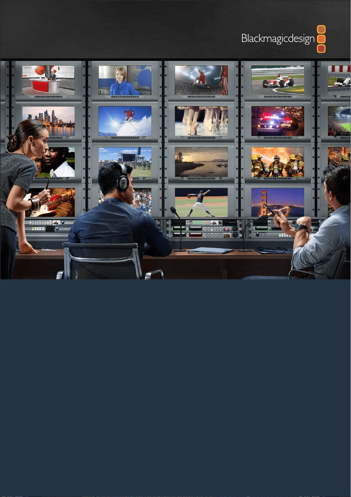

Bienvenue
Nous espérons que vous partagez le même rêve que nous : c'est-à-dire que l'industrie télévisée
soitun lieu créatif qui permette à chacun d'avoir accès à la plus haute qualité vidéo qui soit.
Le monitoring vidéo est nécessaire dans tous les studios. Le SmartView 4K est doté d’un écran LCD 4K
natif, vous pouvez ainsi visionner de la vidéo Ultra HD en pleine résolution. De plus, son boîtier de 6
unités de rack comprend un panneau de contrôle qui permet de modifier rapidement les paramètres.
Le SmartView HD offre quant à lui un écran LCD de 17 pouces, dans un design de 6 unités de rack
et de moins d’un pouce d’épaisseur. Le SmartView Duo intègre deux écrans LCD indépendants de
8pouces dans un format de 3 unités de rack et de moins d’un pouce d’épaisseur. Enfin, le SmartScope
Duo 4K comprend deux écrans LCD indépendants de 8 pouces ainsi qu’une fonction d’affichage de
la forme d’onde, vous pouvez donc vérifier les niveaux de votre vidéo à la volée. Tous les moniteurs
SmartView prennent en charge la vidéo SD, HD et 2K via 3G-SDI. Le SmartScope Duo 4K et le
SmartView 4K supportent même l'Ultra HD 4K via 6G-SDI et 12G-SDI respectivement !
Ces solutions de monitoring vidéo ont été conçues pour fonctionner dès leur sortie de l'emballage.
De plus, le logiciel Blackmagic SmartView Setup offre aux utilisateurs un outil de configuration
simple et intuitif.
Ce manuel d'utilisation devrait contenir toutes les informations dont vous avez besoin pour la mise
en route de votre SmartView ou SmartScope. Il vous est toutefois recommandé de faire appel à
dupersonnel qualifié en cas de doute sur ce qu'est une adresse IP ou si vous souhaitez davantage
d'informations sur les réseaux d'ordinateurs. Les produits SmartView et SmartScope sont faciles à
installer. Il y a toutefois quelques préférences techniques qu'il vous faudra configurer après l'installation.
L'installation devrait vous prendre 5 minutes. Veuillez consulter notre site Internet
www.blackmagicdesign.com/fr et notre page d'assistance pour télécharger les dernières mises
à jour de ce manuel et du logiciel SmartView. Enfin, veuillez enregistrer votre équipement lors
du téléchargement des mises à jour afin que nous puissions vous tenir informés de la sortie d'un
nouveau logiciel. Nous travaillons constamment sur de nouvelles fonctionnalités et nous nous
efforçons d’améliorer nos services en permanence : c’est pourquoi nous aimerions avoir votre avis !
Grant Petty
PDG de Blackmagic Design

Sommaire
SmartView & SmartScope
Mise en route 81
Découverte du SmartView et du SmartScope 81
Connecter des sources vidéo 82
Connecter un ordinateur 82
Installer le Blackmagic SmartView Setup 83
Utiliser le Blackmagic SmartViewSetup 84
Mise à jour du logiciel 84
Ajuster les paramètres du moniteur 84
Utiliser le SmartView 4K 87
Découvrir le Blackmagic SmartView 4K 87
Boutons de contrôle 88
Charger des LUTs 3D à l’aide du Blackmagic SmartView Setup 90
Utiliser SmartScope Duo 4K 91
Qu'est-ce que le Blackmagic SmartScope ? 91
Achage Video Monitoring 91
Achage Waveform 92
Achage Vectorscope 93
Achages Parade 95
Achage Histogram 96
Achages des niveaux audio 97
Connexion à un réseau 98
Connexion Ethernet directe 99
Commutateur réseau Ethernet 99
Modifier les paramètres réseau 101
Paramètres réseau 101
Ajouter un moniteur Blackmagic 102
Utilisation du tally 103
Broches du port tally 103
Optimiser l'angle de vision 104
Developer Information 106
Blackmagic 2K Format – Overview 106
Blackmagic 2K Format – Vertical Timing Reference 107
Blackmagic 2K Format – Data Stream Format 108
Blackmagic SmartView Ethernet Protocol v1.3 109
Assistance 113
Avertissements et informations desécurité 114
Garantie 115
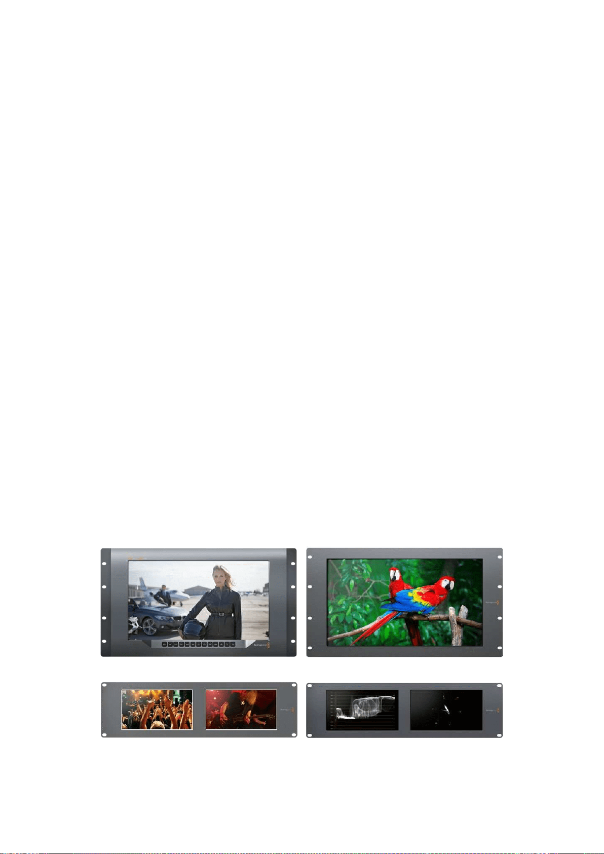
81Mise en route
Mise en route
Découverte du SmartView et du SmartScope
Les moniteurs SmartView sont des outils de choix pour les studios qui ont besoin d’une solution de
monitoring sur rack. Pour les mettre en route, il suffit de les brancher à une source d'alimentation
et de connecter une source SDI !
Le SmartView 4K possède un écran LCD 4K de 15,6 pouces, vous pouvez donc afficher de la vidéo
SD, HD ou Ultra HD dans sa résolution native de 3840x2160. Les boutons situés sur la face avant de
l’appareil vous permettent de sélectionner facilement les entrées, d’ajuster la luminosité de l’écran,
de vérifier s’il y a du bruit dans le canal bleu, d’afficher les informations de blanking, d’appliquer des
LUTs 3D et autres.
Le SmartView HD intègre un écran LCD HD de 17 pouces qui est parfait pour le monitoring en HD
pleine résolution.
Le SmartView Duo dispose de deux moniteurs pour afficher simultanément différents signaux vidéo.
Vous pouvez par exemple afficher un signal YUV 4:2:2 sur le premier moniteur et un signal RVB 4:4:4
sur le deuxième, ou encore un signal NTSC sur un moniteur et un signal PAL sur l’autre. Réalisez de
nombreuses combinaisons, en connectant simplement un câble SDI à chaque moniteur !
SmartScope Duo 4K intègre les mêmes fonctionnalités que SmartView Duo, mais il permet également
d’afficher la forme d’onde, le vecteurscope et d’autres scopes populaires pour le monitoring de la
vidéo et de l’audio en temps réel. De plus, vous disposez d’une prise en charge intégrale de
l’Ultra HD 4K !
Toutes les entrées SDI des moniteurs SmartView et SmartScope supportent la détection automatique
de la SD, de la HD ou du 3G-SDI, y compris la vidéo 2K. Le SmartView 4K détecte également l’Ultra
HD via 12G-SDI, notamment les formats tels que 2160p60. Le SmartScope Duo 4K, quant à lui,
détecte automatiquement la vidéo Ultra HD 4K via 6G-SDI.
Si vous souhaitez ajuster à distance les paramètres de plusieurs appareils SmartView et SmartScope à
partir d’un ordinateur, vous pouvez les relier ensemble via Ethernet. Ainsi, vous n’aurez pas besoin de
brancher un ordinateur à chaque appareil via USB à chaque fois que vous devez ajuster des paramètres.
C'est tout ce que vous devez savoir pour commencer ! Veuillez lire ce qui suit pour obtenir de plus
amples informations concernant la connexion du SmartView et du SmartScope, la configuration des
paramètres du moniteur à l’aide du Blackmagic SmartView Setup et la connexion à un réseau.
SmartView 4K SmartView HD
SmartView Duo SmartScope Duo 4K

82Mise en route
Connecter des sources vidéo
Les moniteurs SmartView et SmartScope intègrent des connecteurs BNC standard pour connecter des
équipements SDI, tels que des mélangeurs, des caméras, des cartes d’acquisition et des enregistreurs.
Acher une image
Afficher une image est un jeu d’enfant ! Il suffit de mettre l’appareil en marche et de connecter une
source vidéo à une entrée SDI. Une fois l’appareil alimenté et connecté, la vidéo devrait s’afficher
immédiatement. Les signaux SD, HD et 2K sont détectés automatiquement par l’entrée et la sortie
en boucle SDI. Le SmartView 4K et le SmartScope Duo 4K détectent également l’Ultra HD 4K.
Lorsque l’appareil ne reçoit pas de vidéo, le rétro-éclairage s’éteint afin d’économiser de l’énergie
jusqu’à ce qu’un signal valide soit reçu.
Relier les moniteurs en chaîne
Chaque moniteur SmartView et SmartScope possède sa propre entrée SDI indépendante ainsi
qu’une sortie en boucle afin que vous puissiez relier plusieurs moniteurs en chaîne pour afficher
le même signal d’entrée :
1 Alimentez l’appareil 1. Connectez une source vidéo à une entrée SDI. La vidéo devrait
s’afficher immédiatement.
2 Alimentez l’appareil 2. Connectez un câble SDI entre la sortie en boucle de l’appareil 1 et
l'entrée SDI de l’appareil 2.
Il n'y a pas de limite au nombre d’appareils que vous pouvez relier.
Si vous faites du monitoring de forme d'onde avec le SmartScope Duo 4K, vous souhaiterez sans doute
relier la sortie du moniteur 1 au moniteur 2 afin que les deux écrans affichent le même signal d’entrée.
Une fois la vidéo affichée, vous pouvez ajuster les paramètres des moniteurs, ou sélectionner des
scopes sur le SmartScope Duo 4K à l’aide du logiciel SmartView Setup. Vous pouvez également
utiliser ce logiciel pour charger des LUTs 3D sur le Blackmagic SmartView 4K.
SmartView 4K SmartView HD
SmartView Duo
SmartScope Duo 4K
Connecter un ordinateur
Configurez les paramètres du moniteur SmartView ou SmartScope en le connectant à votre
ordinateur via USB et en installant le logiciel Blackmagic SmartView Setup.
La connexion USB permet également d’effectuer des mises à jour logicielles téléchargées sur le site
Internet de Blackmagic Design. Ces mises à jour peuvent offrir de nouvelles fonctionnalités, une
compatibilité avec du nouveau matériel ou une prise en charge de nouveaux formats. Le logiciel
Blackmagic SmartView Setup peut être installé sur les ordinateurs macOS et Windows.
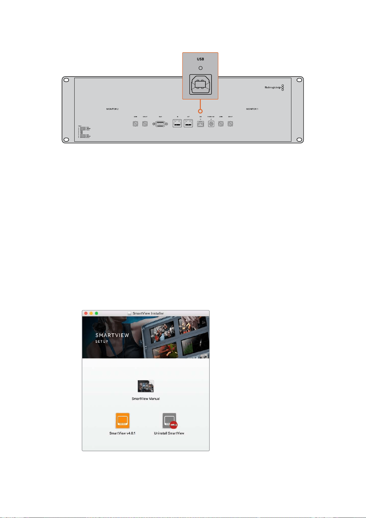
83Mise en route
Installer le Blackmagic SmartView Setup
Le Blackmagic SmartView Setup est compatible avec les dernières versions Sierra et High Sierra de
macOS, et avec les versions 64 bits de Windows 8.1 et Windows 10 si les derniers service pack sont
installés. Si vous le souhaitez, le Blackmagic SmartView Setup peut être installé sur plusieurs
ordinateurs en réseau.
La carte SD fournie avec le SmartView contient le programme d’installation du logiciel. Toutefois,
nous vous conseillons de consulter le site www.blackmagicdesign.com/fr/support pour vous assurer
que vous disposez de la dernière version.
Installation sur macOS :
Ouvrez la carte SD fournie, ou l’image disque téléchargée, et double-cliquez sur l’icône d’installation
SmartView. Un dossier SmartView sera créé dans le dossier Applications. Il contiendra le logiciel
SmartView Setup, un désinstalleur pour supprimer les anciennes versions lors des mises à jour,
et un dossier documents contenant ce manuel et d’autres informations relatives à SmartView.
Installation sur Windows :
Sur Windows, ouvrez la carte SD qui vous a été fournie, ou le fichier zip téléchargé, et double-cliquez
sur le programme d’installation SmartView. Suivez les instructions à l’écran pour installer le logiciel.
Pour installer le logiciel sur macOS, ouvrez le fichier SmartView.dmg
sur la carte SD fournie, ou dans le dossier Downloads, puis
double-cliquez sur l’icône d’installation SmartView.
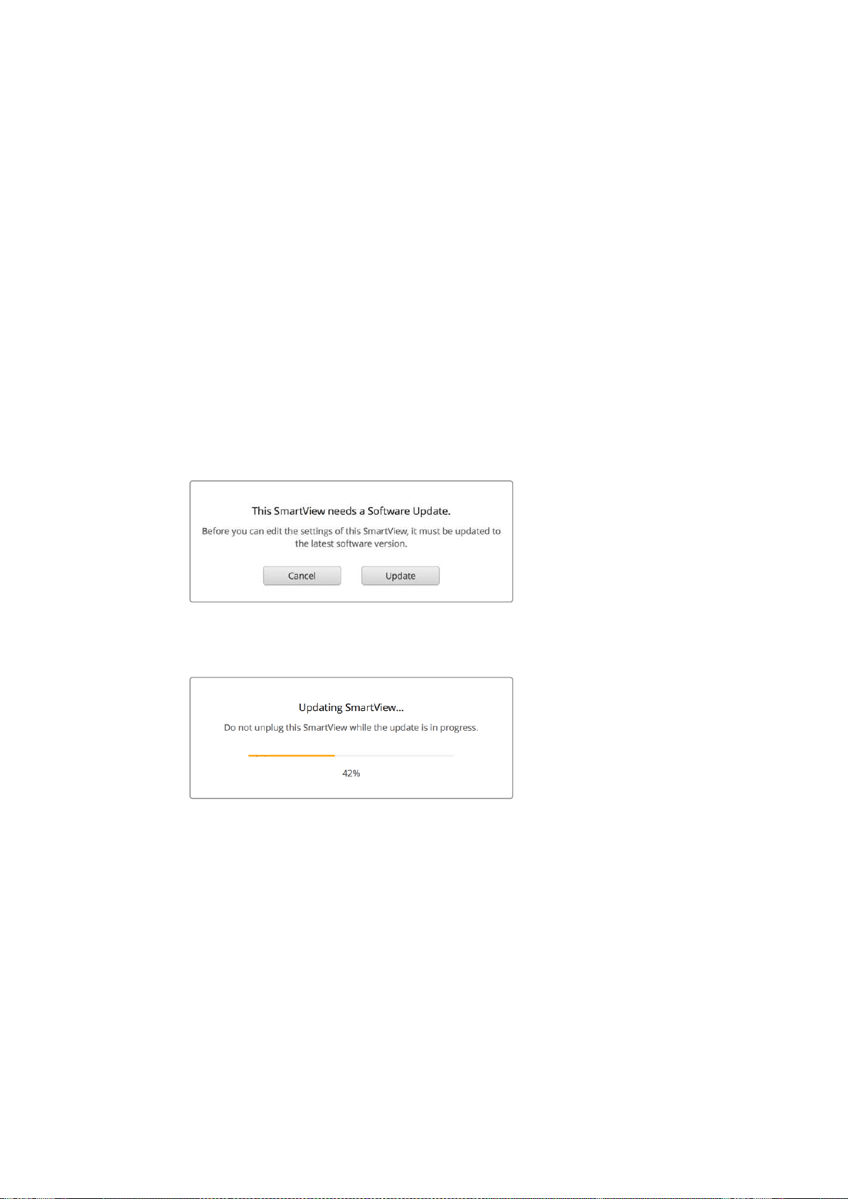
84Utiliser le Blackmagic SmartViewSetup
Utiliser le Blackmagic SmartViewSetup
Mise à jour du logiciel
Une fois que vous avez installé et ouvert le SmartView Setup, cliquez sur l’icône de paramétrage
située sous le nom du moniteur. Une mise à jour du logiciel interne de votre SmartView ou
SmartScope vous sera peut-être proposée. Pour ce faire :
1 Connectez votre SmartView ou SmartScope à un ordinateur via USB ou Ethernet, puis
ouvrez le Blackmagic SmartView Setup.
2 Lorsque le message s’affiche, cliquez sur Update. La mise à jour peut prendre
quelques minutes.
3 Le message : "This SmartView has been updated" (Ce SmartView a été mis à jour) devrait
s'afficher à l'écran une fois la mise à jour effectuée.
4 Cliquez sur Close.
Si aucune mise à jour logicielle n'est requise, le Blackmagic SmartView Setup ouvrira la page de
configuration de votre moniteur.
Lorsque vous lancez le SmartView Setup et que vous cliquez sur
l’icône de paramétrage du SmartView ou SmartScope connecté,
ce message apparaît si une mise à jour est requise.
La mise à jour prendra environ 5 minutes.
Ajuster les paramètres du moniteur
Une fois ouvert, l'utilitaire Blackmagic SmartView Setup cherche automatiquement les appareils
SmartView ou SmartScope connectés via USB ou Ethernet, et les affiche sur la page d’accueil du
SmartView Setup. Si plusieurs moniteurs Blackmagic sont connectés à votre réseau, cliquez sur les
flèches situées sur les côtés gauche et droit de la page d'accueil pour sélectionner le moniteur que
vous souhaitez ajuster. Si votre moniteur Blackmagic est connecté via USB, une icône USB
apparaîtra à côté du nom du moniteur.
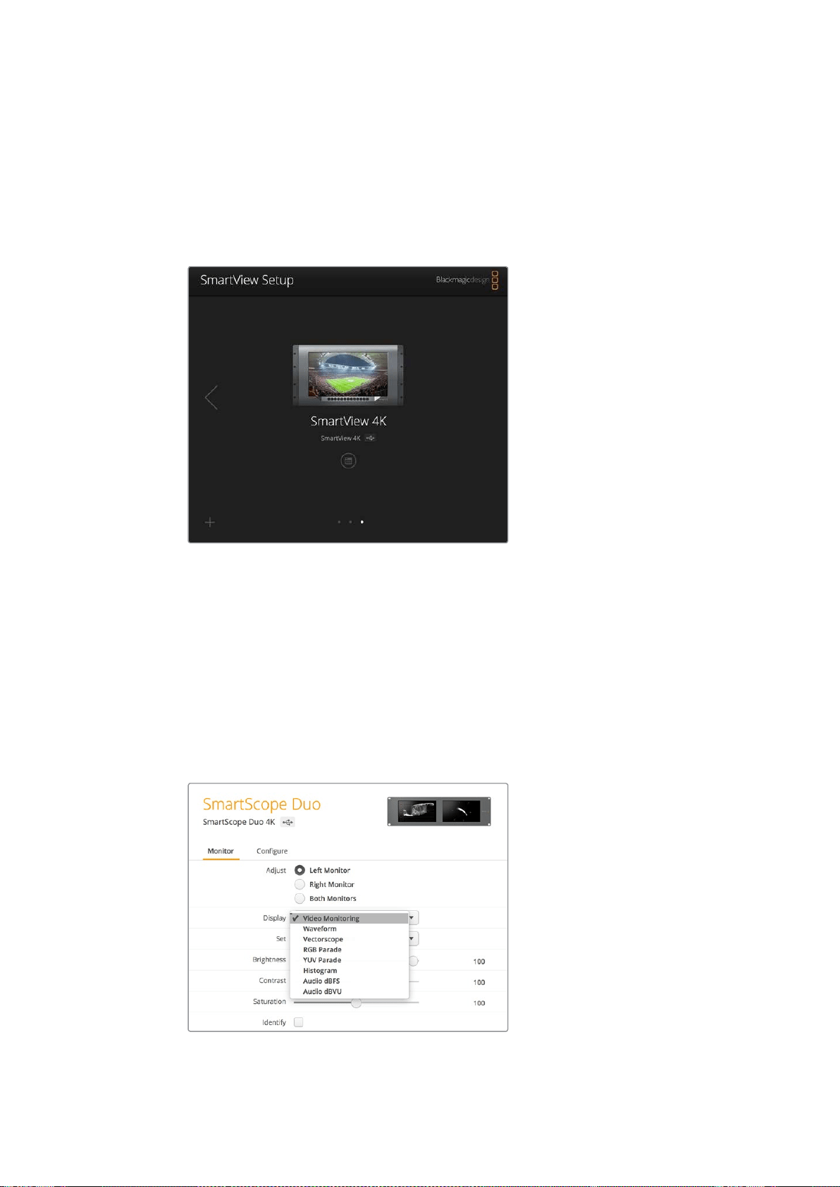
85Utiliser le Blackmagic SmartViewSetup
Pour ajuster des paramètres, sélectionnez le moniteur connecté via Ethernet ou USB, et cliquez sur
l’icône de paramétrage située sous le nom du moniteur. La page de configuration du moniteur
sélectionné s’ouvrira. Une fois que vous êtes satisfait des nouveaux paramètres, cliquez sur le bouton
Save afin de sauvegarder les paramètres et de retourner sur la page d’accueil du SmartView Setup.
Consultez la section suivante pour obtenir plus d'informations concernant le réglage des paramètres des
moniteurs Blackmagic. Pour obtenir plus d’informations sur la configuration des paramètres réseau à l’aide
du Blackmagic SmartView Setup, consultez la section «Ajuster les paramètres réseau» de ce manuel.
Le logiciel Blackmagic SmartView Setup recherche automatiquement
les appareils SmartView et SmartScope connectés localement via
USB ou sur un réseau.Lorsque vous mettez à jour le logiciel interne
du moniteur, veillez à ce que le moniteur soit connecté via USB ou
Ethernet. Une icône USB apparaîtra à côté du nom du moniteur.
Paramètres du moniteur
Pour ajuster les paramètres et les affichages de chaque moniteur, il faut les connecter via Ethernet
ou USB. Sélectionnez le moniteur que vous souhaitez régler en cliquant sur les flèches gauche et
droite de la page d’accueil du SmartView Setup, puis cliquez sur l’icône de paramétrage située sous
le nom du moniteur. La page de configuration est automatiquement personnalisée afin de
correspondre aux fonctionnalités offertes par le moniteur Blackmagic sélectionné.
Sur SmartScope, vous pouvez choisir entre les scopes et
le monitoring vidéo dans le menu déroulant Display.
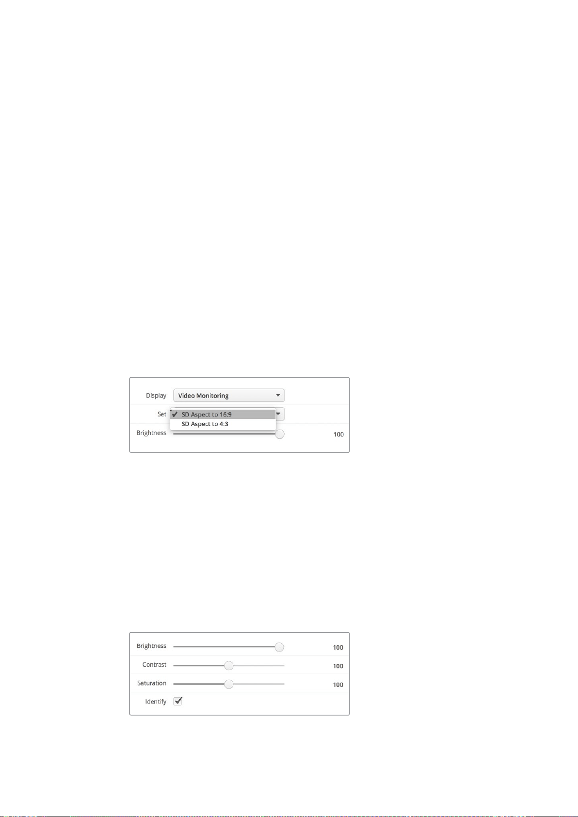
86Utiliser le Blackmagic SmartViewSetup
Paramètre Adjust
Lorsque vous utilisez un SmartScope ou un SmartView Duo, choisissez le(s) moniteur(s) que vous
souhaitez ajuster en sélectionnant Left Monitor, Right Monitor ou Both Monitors. Lorsque le
paramètre Both Monitors est activé, les ajustements de luminosité, de contraste et de saturation
seront appliqués aux deux moniteurs de SmartView Duo et de SmartScope.
Paramètre Display
Lorsque vous utilisez un SmartScope, le menu déroulant Display vous permet de sélectionner
lesscopes. Sélectionnez Video Monitoring si vous souhaitez uniquement afficher l’image vidéo.
Paramètre Set
Sur le SmartScope, le menu déroulant Set vous permet de sélectionner un format 4:3 ou 16:9 pour
lemonitoring vidéo lorsque vous travaillez avec de la vidéo SD. Le menu déroulant Set offre des
options supplémentaires pour l’affichage sélectionné, notamment vecteurscope, audio dBFS et
audio dBVU.
Video Monitoring : Choisissez d’afficher l’image vidéo au format 4:3 ou 16:9.
Pour visionner de la vidéo SD au format large anamorphosé, choisissez 16:9. En revanche,
pour visionner de la vidéo SD standard, choisissez 4:3.
Vectorscope : Choisissez si votre entrée repose sur une mire de barres couleurs de
100%ou de 75%.
Audio dBFS : Choisissez la paire de canaux audio pour le monitoring de la phase.
Audio dBVU : Choisissez la paire de canaux audio pour le monitoring de la phase.
Pour visionner de la vidéo SD au format large anamorphosé,
choisissez SD Aspect to 16:9.
Paramètres Brightness, Contrast, Saturation
Déplacez les curseurs pour ajuster la luminosité, le contraste et la saturation.
Case Identify
Lorsque la case Identify est cochée, les moniteurs sélectionnés dans le Blackmagic SmartView
Setup afficheront une bordure blanche. Lorsque plusieurs appareils SmartView et SmartScope sont
connectés sur un réseau, ce paramètre permet d’identifier facilement le moniteur sélectionné.
Lorsque ce paramètre est utilisé conjointement avec le paramètre Both Monitors, la bordure
blanche s’affichera sur les deux moniteurs de SmartView Duo ou de SmartScope Duo 4K.
Déplacez les curseurs vers la gauche ou vers la droite pour ajuster la
luminosité, le contraste et la saturation. Cochez la case Identify
pour identifier le moniteur sélectionné.
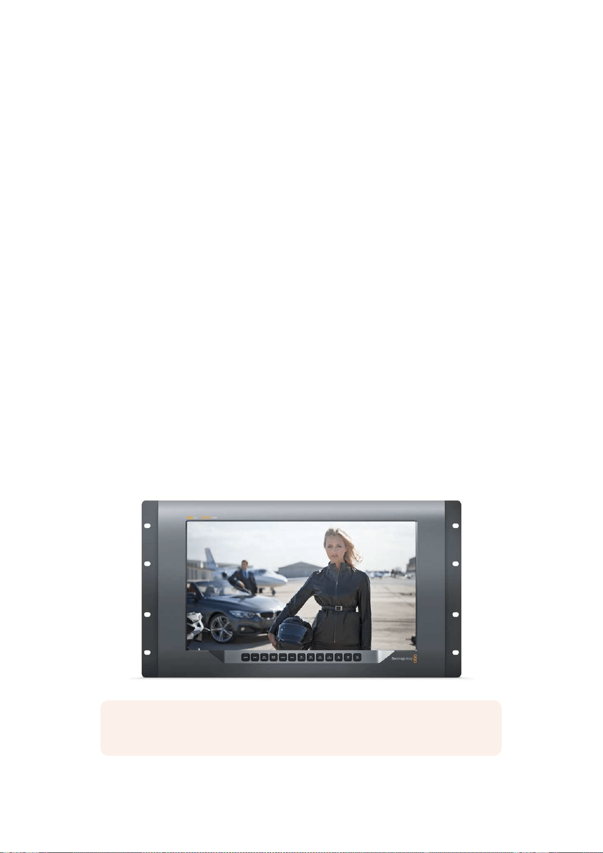
87Utiliser le SmartView 4K
Utiliser le SmartView 4K
Découvrir le Blackmagic SmartView 4K
Le SmartView 4K est un moniteur broadcast Ultra HD de 6 unités de rack, doté de connexions
12G-SDI permettant un affichage de la vidéo SD, HD et Ultra HD jusqu'à 2160p60. Avec son écran
lumineux et son large angle de vision, le SmartView 4K offre une image nette aux couleurs vives
pour une mise au point et un monitoring des couleurs précis. De plus, il prend en charge la plupart
des formats vidéo.
Conçu pour une utilisation en studio et en extérieur, le SmartView 4K offre une excellente prise en
main. Grâce à ses connexions sur la face latérale et sa prise en charge des normes VESA, l’appareil
peut être installé dans des espaces restreints, sur un mur ou sur un bras articulé. Le SmartView 4K
peut être contrôlé à l'aide du panneau de commande intégré, ou à distance via Ethernet lorsque le
panneau avant n’est pas accessible.
Les deux entrées 12G-SDI multidébits vous permettent de choisir entre deux sources SDI, et grâce
au logement pour module SFP conforme aux normes SMPTE, vous pouvez ajouter un module SDI
fibre optique et connecter votre vidéo via fibre optique. Le SmartView 4K intègre également une
sortie 12G-SDI pour acheminer votre vidéo vers d’autres équipements, deux connecteurs Ethernet
pour la connexion en réseau, le contrôle à distance et une sortie en boucle permettant une liaison
en cascade avec d’autres moniteurs. De plus, il est doté d’une entrée tally pour la production en
direct et d’un port USB pour les mises à jour du logiciel interne.
Vous pouvez même charger des LUTs 3D conformes aux normes de l’industrie avec l’extension .cube
ou des LUTs DaVinci Resolve à l’aide du Blackmagic SmartView Setup. En outre, les LUTs 3D vous
permettent de connecter le SmartView 4K directement à la caméra et de visionner vos clips juste avant
l’étalonnage final. Grâce aux deux niveaux de focus peaking, la mise au point de vos plans sera toujours
impeccable. De plus, la prise en charge du courant alternatif et du courant continu vous permet de
brancher l’appareil à une prise secteur ou à une batterie externe pour vous déplacer sur le plateau.
Le SmartView 4K est la solution de monitoring idéale pour la production broadcast en extérieur et
en studio, car il affiche la vidéo en SD, HD et Ultra HD dans sa résolution native de 3840x2160.
REMARQUE Lorsque vous connectez l’alimentation externe via l’entrée d’alimentation DC,
veillez à ce que la sortie d’alimentation externe puisse prendre en charge 24 watts à 12 volts.
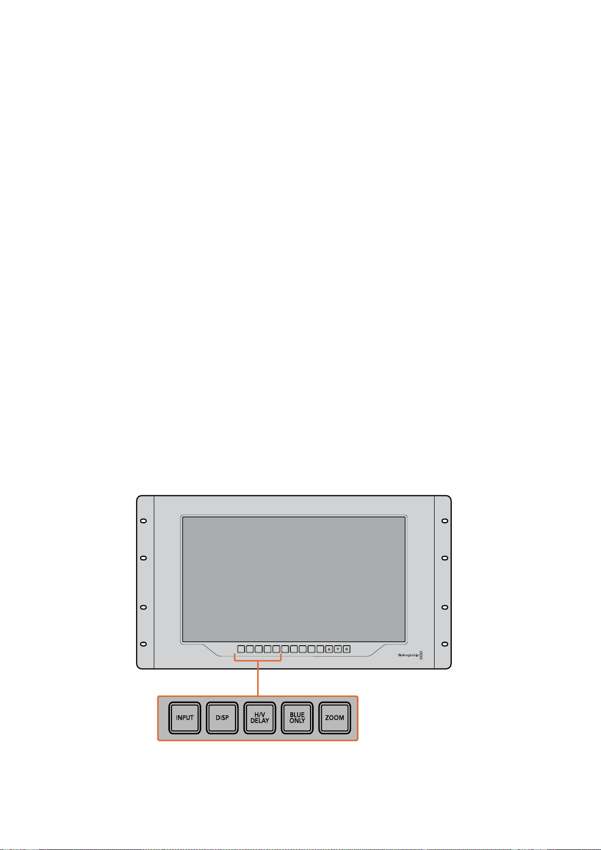
88Utiliser le SmartView 4K
Boutons de contrôle
Le panneau de contrôle intègre une rangée de boutons pour ajuster rapidement les paramètres
du SmartView 4K.
Bouton Input
Appuyez sur ce bouton pour passer en revue tous les signaux vidéo connectés aux entrées 12G-SDI
du SmartView 4K et à l’entrée du module SFP fibre optique en option. Lorsqu’aucune vidéo n’est
connectée, l’entrée en question affiche un signal noir. Lorsque vous commutez entre les entrées,
des informations concernant le format de l’entrée connectée s’affichent momentanément en haut
à gauche du moniteur.
Bouton Disp
Le bouton Disp permet de régler la luminosité de l’écran LCD du SmartView 4K. Ajustez la luminosité
en appuyant sur les flèches haute et basse. Appuyez à nouveau sur le bouton Disp pour fermer ce
paramètre.
Bouton H/V Delay
Le bouton H/V Delay vous permet de confirmer rapidement la présence de données auxiliaires au
sein du signal vidéo SDI. Par exemple, appuyez une fois sur le bouton H/V Delay pour visualiser
les données auxiliaires horizontales. Appuyez à nouveau sur ce bouton pour afficher les données
auxiliaires verticales, utilisées couramment pour le sous-titrage codé.
Bouton Blue Only
Si le signal vidéo numérique comporte du bruit, celui-ci est plus visible au sein du canal bleu. Vous
pouvez donc facilement vérifier si le signal est bruité en appuyant sur le bouton Blue Only. Cette
fonction affiche uniquement le canal bleu, représenté par une image en noir et blanc. Cette image
en noir et blanc peut également être utilisée lorsque vous vérifiez la mise au point de la caméra.
Bouton Zoom
Une façon d’obtenir une mise au point impeccable sur la caméra est d’utiliser le bouton Zoom.
Appuyez une fois pour zoomer dans l’image. Vous pouvez ainsi facilement voir si un objet est net.
Appuyez une nouvelle fois pour rétablir l'image.
INPUT DISP
H/V
DELAY
3D
LUT 1
BLUE
ONLY
ZOOM PEAK
3D
LUT 2
H
MARK
V
MARK
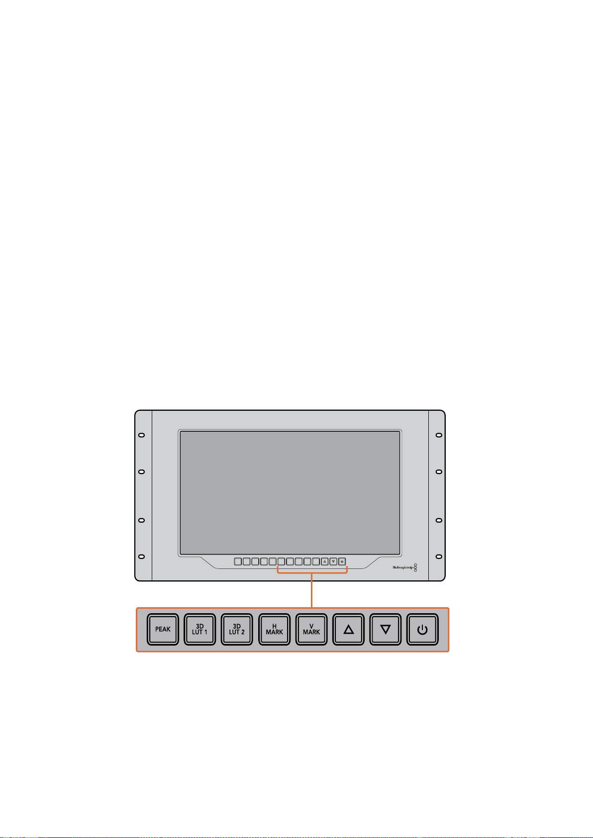
89Utiliser le SmartView 4K
Bouton Peak
Appuyez sur le bouton Peak pour activer le focus peaking afin de vérifier facilement la mise au point
de la caméra. Cette fonction affiche un contour vert autour des zones les plus nettes de l'image.
Vous pouvez commuter entre deux niveaux de peaking en appuyant plusieurs fois sur ce bouton.
Des contours verts très prononcés indiquent que l’image de la caméra est nette.
3D LUT 1 et 3D LUT 2
Les boutons LUT vous permettent de visualiser votre image à l’aide de LUTs 3D personnalisées
générées dans DaVinci Resolve ou de LUTs .cube conformes aux normes de l’industrie. Appuyez
surun des boutons LUT pour activer la LUT en question. Touchez à nouveau pour la désactiver.
Pourplus d'informations sur l’utilisation des LUTs 3D avec le SmartView 4K, consultez lasection
« Charger des LUTs 3D à l’aide du Blackmagic SmartView Setup ».
Boutons H Mark et V Mark
Vous pouvez visualiser et modifier les repères d'image à l’aide des boutons H Mark et V Mark.
Les repères d’image facilitent la composition des plans et vous permettent de positionner des
informations importantes ou des graphiques au sein de la zone de sécurité de l’écran. Comme la
bordure du signal vidéo affichée à l’écran varie selon le téléviseur, il est donc utile de pouvoir
visualiser la zone de sécurité. La zone de sécurité est la zone de l’écran qui est toujours visible,
quel que soit le téléviseur ou le moniteur utilisé.
Pour afficher les repères d'image horizontaux et verticaux, appuyez sur les boutons H Mark et
VMark respectivement. Pour modifier les repères, appuyez à nouveau sur les mêmes boutons afin
d’afficher les repères en surbrillance. Vous pourrez ainsi modifier la position des repères à l’aide des
flèches haut et bas. Confirmez la nouvelle position des repères en appuyant à nouveau sur les
mêmes boutons. Réappuyer une nouvelle fois sur ces boutons désactive les repères.
Flèches haut et bas
Utilisez les flèches haut et bas pour modifier un paramètre, par exemple pour ajuster la luminosité
de l’écran ou la position des repères d'image.
Bouton de mise en marche
Appuyez une fois sur le bouton de mise en marche pour allumer le SmartView 4K. Appuyez à
nouveau sur le même bouton pour l’éteindre.
INPUT DISP
H/V
DELAY
3D
LUT 1
BLUE
ONLY
ZOOM PEAK
3D
LUT 2
H
MARK
V
MARK
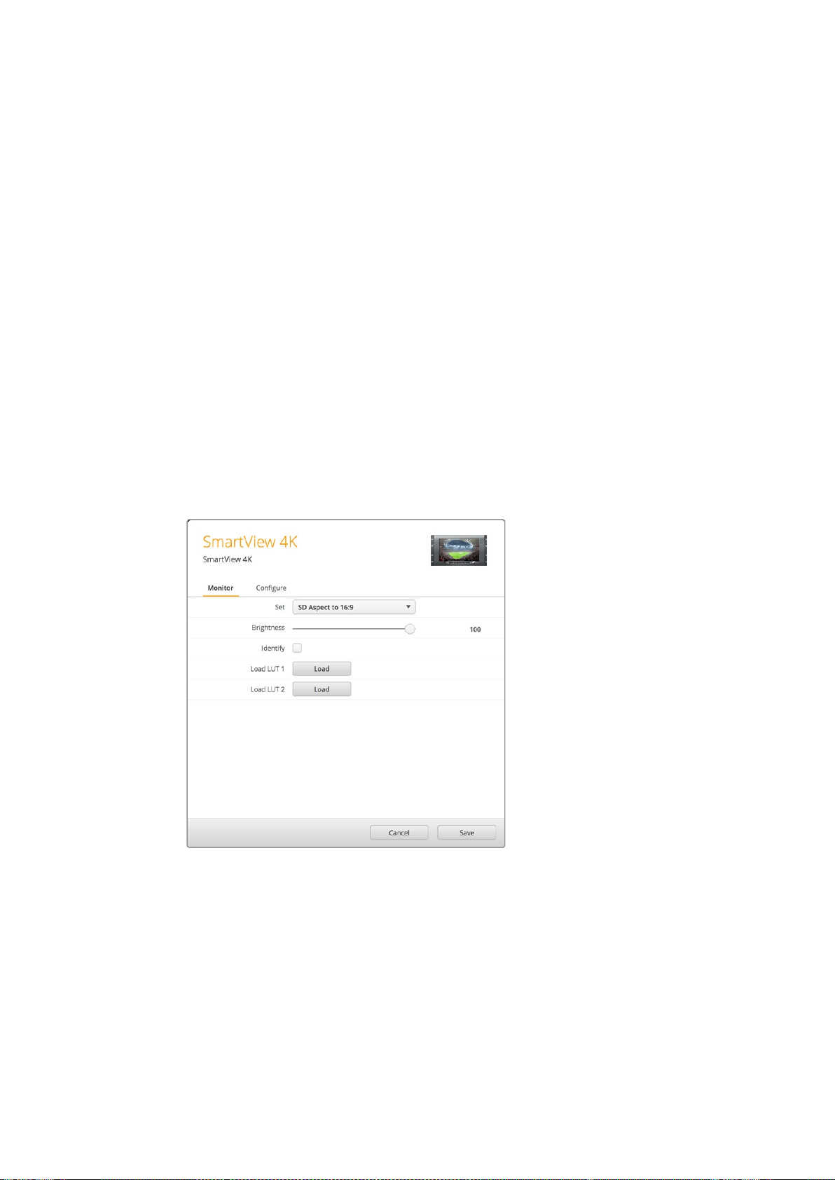
90Utiliser le SmartView 4K
Charger des LUTs 3D à l’aide du
Blackmagic SmartView Setup
Le SmartView 4K vous permet de visualiser votre vidéo à l’aide de LUTs 3D. Ainsi, vous pouvez
calibrer le SmartView 4K à l’aide de LUTs d’étalonnage professionnelles, ou visualiser la vidéo juste
avant l’étalonnage final. Il est également possible d’utiliser les LUTs 3D pour créer différents rendus.
Les LUTs sont chargées dans le SmartView 4K à l’aide du Blackmagic SmartView Setup, et comme
leSmartView 4K prend en charge les fichiers LUT conformes aux normes de l’industrie dotés d’une
extension .cube, vous pouvez même charger des LUTs personnalisées créées sur Blackmagic
DaVinci Resolve. Veuillez consulter le manuel DaVinci Resolve pour obtenir de plus amples
informations sur la création de fichiers LUT.
Charger une LUT 3D dans le 3D LUT 1 :
1 Ouvrez le Blackmagic SmartView Setup.
2 Appuyez sur le bouton Load LUT 1. Une fenêtre s’ouvre pour vous demander quel est
l’emplacement du fichier LUT que vous souhaitez charger. Sélectionnez le fichier LUT .cube
désiré, puis appuyez sur le bouton Open.
3 Pour visualiser la LUT que vous venez de charger, appuyez sur le bouton 3D LUT 1
du panneau de contrôle du SmartView 4K. Appuyez à nouveau sur ce bouton pour
désactiver la LUT.
Suivez la même procédure pour charger un fichier LUT dans le 3D LUT 2.
Utilisez le Blackmagic SmartView Setup pour
charger des LUTs 3D sur le SmartView 4K.

91Utiliser SmartScope Duo 4K
Utiliser SmartScope Duo 4K
Qu'est-ce que le Blackmagic SmartScope ?
Dans le passé, les scopes de télédiffusion et de postproduction coûtaient extrêmement cher et
étaient peu pratiques, car on ne pouvait visualiser qu'un seul scope à la fois sur un écran minuscule.
Certains scopes sont inesthétiques et il est donc préférable qu’ils ne soient pas visibles.
Grâce au SmartScope Duo 4K, vous disposez de moniteurs de forme d’onde qui vous permettent
d’afficher tous les aspects de votre signal vidéo sur deux moniteurs en temps réel. Tous les
ajustements apportés au signal d’entrée à l’aide du Blackmagic SmartView Setup sont
immédiatement visibles sur le SmartScope Duo 4K. De plus, chaque signal d’entrée peut être
envoyé sur le moniteur de votre choix via la sortie en boucle SDI. Vous pouvez ainsi utiliser le
moniteur de droite pour afficher le scope du signal reçu par le moniteur de gauche.
Les scopes affichés sur le SmartScope Duo 4K sont sélectionnés dans le logiciel Blackmagic
SmartView Setup. Choisissez le scope désiré dans le menu déroulant Display.
Consultez les pages suivantes pour obtenir des informations concernant l’utilisation de chaque
scope afin que vous puissiez mieux comprendre l’aide qu’il peut vous apporter.
Il est facile de régler le Blackmagic SmartScope Duo 4K à l’aide du Blackmagic
SmartView Setup pour qu’il affiche un scope différent sur chaque moniteur.
Affichage Video Monitoring
L'affichage Video Monitoring est un écran de contrôle très pratique qui vous permet de visualiser
lavidéo reçue par SmartScope.
Si votre signal d’entrée est en SD, vous pouvez choisir entre un affichage 4:3 pillarbox ou 16:9 à
partir du menu déroulant Set. Tous les changements apportés aux paramètres de luminosité, de
contraste et de saturation de l’écran LCD sont immédiatement visibles sur cet affichage. Notez
toutefois que ces changements n’affectent que le moniteur. Comme le signal vidéo reste inchangé,
les scopes ne seront pas affectés par les ajustements de saturation et de luminosité.
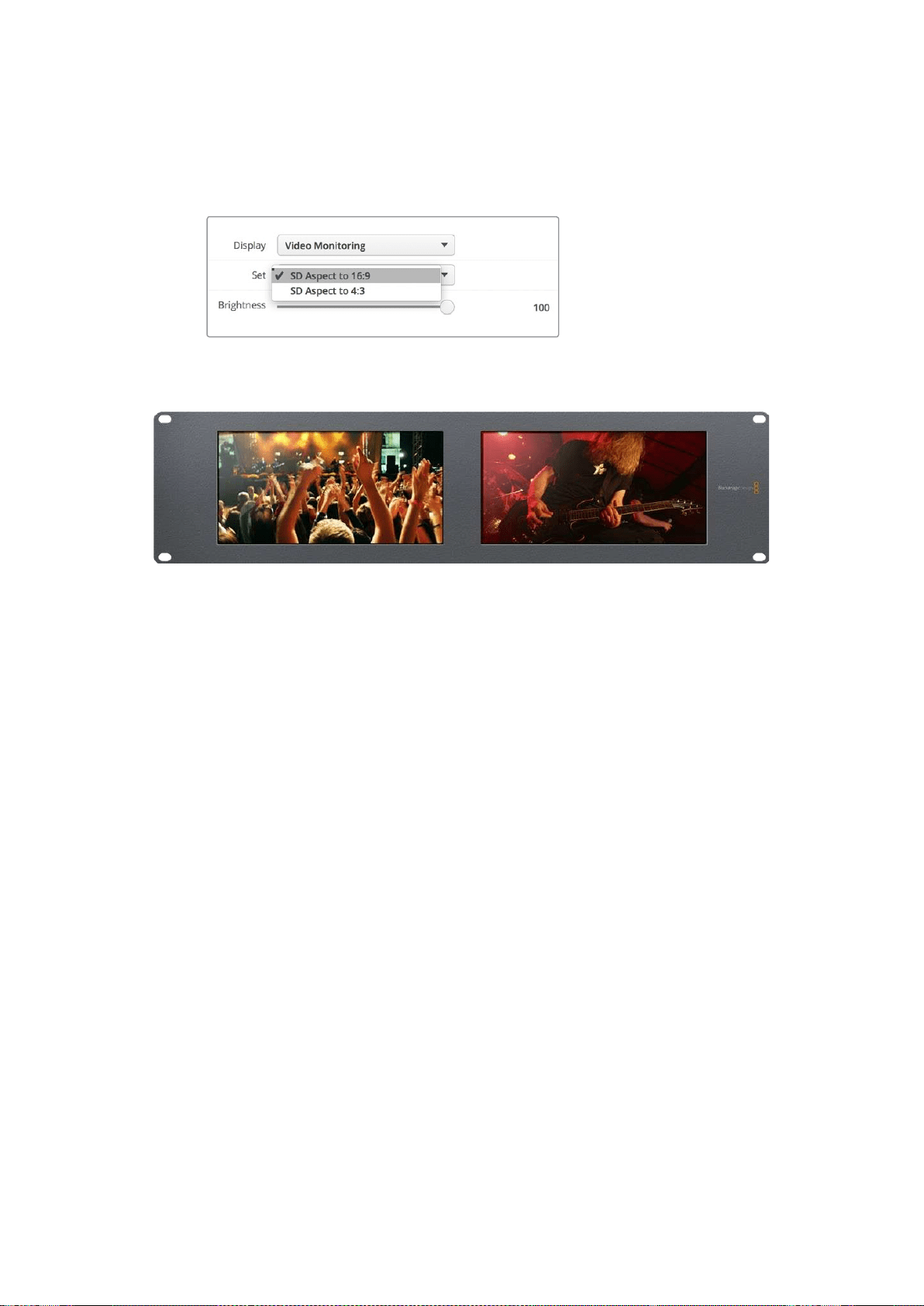
92Utiliser SmartScope Duo 4K
Il est souvent utile de régler un moniteur sur Video Monitoring et l’autre sur un scope de votre choix.
Pour ce faire, utilisez un petit câble pour connecter la sortie en boucle SDI du moniteur 1 à l’entrée
SDI du moniteur 2.
Vous pouvez visualiser la vidéo SD au format 4:3 pillarbox ou 16:9 écran large
à partir de l’option Set du Blackmagic SmartView Setup. Pour visionner de la
vidéo SD au format large anamorphosé, choisissez SD Aspect to 16:9.
L’af f ic ha ge Video Monitoring affiche le signal vidéo tel
qu’ilapparaîtrait sur un téléviseur ou un moniteur.
Affichage Waveform
L’affichage Waveform affiche une forme d’onde encodée numériquement qui ressemble à celle
desmoniteurs de forme d'onde traditionnels. Il est utilisé pour contrôler et ajuster les niveaux de
luminance (luminosité) du signal vidéo.
Les moniteurs de forme d'onde traditionnels ne prennent en charge que la vidéo analogique
composite en définition standard. Toutefois, l'affichage Waveform du SmartScope Duo 4K prend
également en charge la HD et l’Ultra HD. Vous disposez ainsi d'un moyen aisé d'ajuster les niveaux
de luminance, même lorsque vous faites du monitoring sur des formats vidéo numériques en haute
définition.
Sélectionnez Waveform dans le menu déroulant Display du Blackmagic SmartView Setup. Veillez
àce que le niveau des noirs de votre forme d’onde ne descende pas en dessous de 0% et que le
niveau des blancs ne dépasse pas 100%, ce qui représenterait des valeurs de luminance illégales.
L’affichage de la forme d’onde est une représentation graphique de l’image. Elle indique la valeur de
luminance correspondante à son emplacement dans l’image. Par exemple, si une zone du ciel est
surexposée, vous le verrez au même emplacement horizontal sur la forme d‘onde que dans l’image.
La forme d’onde apparaîtra différemment selon votre séquence. Si vous travaillez sur une vidéo avec
un fort contraste, vous ne verrez aucune valeur dans les tons moyens. L’image ci-dessous affiche la
forme d’onde d’une image bien exposée. Elle comprend une zone foncée à gauche, et des zones
plus claires à partir du centre de l’image jusqu’à sa droite.

93Utiliser SmartScope Duo 4K
L’affichage Waveform montre les valeurs de luminance.
Sélectionnez Waveform dans les paramètres Display du Blackmagic
SmartView Setup pour afficher les valeurs de luminance du signal vidéo.
Affichage Vectorscope
Le vecteurscope utilise un vecteur pour indiquer les couleurs présentes dans le signal vidéo. Selon
la norme de la mire de barres couleurs utilisée, sélectionnez 100% ou 75% dans le menu déroulant
Set du Blackmagic SmartView Setup.
Certains pensent qu'il est possible d'utiliser un vecteurscope pour vérifier s'il y a des niveaux
illégaux. En fait, c'est une idée fausse car c'est l'affichage Parade RGB qui permet de vérifier s'il y
ades couleurs illégales. La raison pour laquelle vous ne pouvez pas utiliser un vecteurscope pour
vérifier la présence de niveaux illégaux est que cela nécessite des valeurs de luminance et
chromatiques. Par exemple, les couleurs dont la saturation est très basse ou très haute deviennent
illégales beaucoup plus rapidement que les tons moyens. Comme l'affichage Vectorscope ne
montre que les couleurs et n'indique pas les valeurs de luminance, il ne peut pas être utilisé pour
vérifier s'il y a des couleurs illégales.
L'affichage Vectorscope est le meilleur outil pour contrôler les niveaux de couleur des anciennes
bandes vidéo analogiques où il est nécessaire d'ajuster les niveaux chromatiques. Faites simplement
une lecture du segment de la bande vidéo qui représente la mire et ajustez ensuite les paramètres
Chroma et Hue (teinte) afin de régler les couleurs de la vidéo dans les carrés sur la graticule.
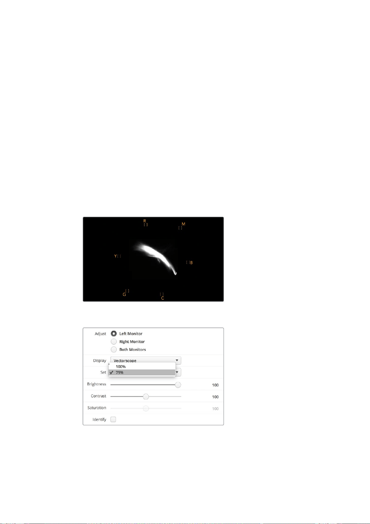
94Utiliser SmartScope Duo 4K
L'affichage Vectorscope est parfait pour l’étalonnage, car il vous permet de voir aisément si la
balance des blancs de votre vidéo est correcte ou si la vidéo est teintée. Lorsque la vidéo est
teintée, l’affichage Vectorscope est décentré, et il se peut que deux points centraux s’affichent.
Normalement, le blanking du signal vidéo crée un point au centre du vecteurscope, car il représente
une zone noire du signal vidéo. Le blanking constitue un bon point de référence pour reconnaître
les zones de la vidéo qui ne comportent pas d’informations de couleur.
Si votre vidéo est teintée, les noirs du signal vont se décentrer. Plus vous éloignerez les points du
centre, plus la teinte de votre vidéo sera prédominante. C'est pourquoi l'affichage Vectorscope est
très efficace pour supprimer une teinte non désirée et rétablir une balance des blancs appropriée.
L'affichage Vectorscope vous permet d'accentuer au maximum les couleurs de votre vidéo tout en
évitant d'ajouter accidentellement des teintes non désirées à vos tons foncés et à vos tons clairs.
Bien que la balance des couleurs puisse être contrôlée sur les affichages Parade RGB et
Vectorscope, les problèmes de balance des couleurs sont souvent plus faciles à repérer sur
le vecteurscope.
Lorsque vous faites de la correction colorimétrique sur des séquences comportant de la peau
humaine, particulièrement des visages, la balance devrait se situer sur une diagonale à environ
10heures sur votre vecteurscope. Cette ligne correspond à la teinte de la peau et est basée sur
lacouleur du sang juste sous la surface de la peau. Elle est donc applicable à toutes les couleurs
depeau et permet de donner une allure naturelle à vos personnages.
Vecteurscope affichant la ligne correspondant à
la teinte de la peau à la position de 10 heures.
Réglez la mire de barres couleurs sur 100% ou sur 75%.
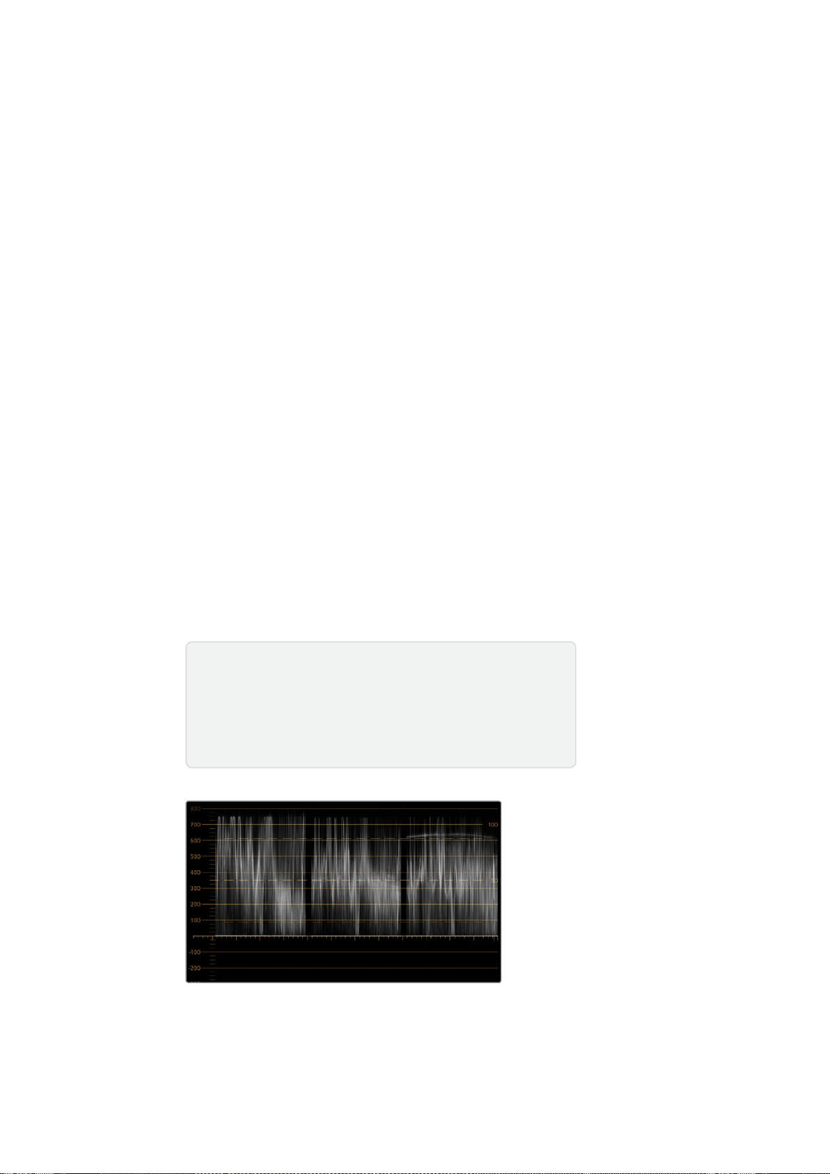
95Utiliser SmartScope Duo 4K
Affichages Parade
Les affichages RGB et YUV Parade sont parfaits pour la correction colorimétrique, ainsi que pour
vérifier les couleurs illégales et les niveaux des couleurs.
Lors de la correction colorimétrique, sélectionnez RBG Parade dans le menu déroulant Display
duBlackmagic SmartView Setup. L’affichage RGB Parade affiche l’intégralité des canaux de couleur
rouge, vert et bleu. Le contrôle des niveaux des canaux de couleur facilite la correction colorimétrique
et la visualisation de la balance des couleurs dans les tons foncés, moyens et clairs du signal vidéo.
L'affichage RGB Parade vous permet d'identifier les détails communs aux canaux rouge, vert et bleu.
Vous pouvez ainsi facilement équilibrer les couleurs et supprimer les nuances de couleur indésirables.
Lors de la correction colorimétrique, il est important de veiller à ce que les niveaux vidéo ne soient
pas écrêtés. Si vous souhaitez augmenter le niveau vidéo, assurez-vous qu'il ne dépasse pas la
limite RGB supérieure, ou vous aurez affaire à des niveaux illégaux. En fonction des appareils que
vous utilisez, certains vous permettront ou non de générer des niveaux RGB illégaux à 100%. Grâce
au SmartScope Duo 4K, vous pouvez visualiser les niveaux illégaux dès qu'ils se produisent.
La vidéo illégale peut survenir dans les tons foncés ainsi que dans les tons clairs. Dans certains
systèmes de correction colorimétrique, les niveaux des tons foncés peuvent être baissés au-dessous
de la ligne 0%. Si vous remarquez des niveaux de tons foncés illégaux, ajoutez un peu de lift ou de
gain pour les éliminer. Toutefois, il faudra contrôler que le signal vidéo n'est pas monté trop haut et n'a
pas généré de couleurs illégales dans les tons clairs.
Pour vérifier les niveaux YUV, sélectionnez YUV Parade dans le menu déroulant Display. Cetaffichage
est utile, car il sépare les valeurs de luma (luminance) et de chroma (chrominance). C’est aussi le format
utilisé pour la diffusion télévisuelle. La forme d’onde de gauche affiche les informations de luminance
tandis que les deux autres formes d’onde affichent les informations dechrominance. L’affichage YUV
Parade est utile pour calibrer les valeurs chromatiques du signal vidéo selon une mire de barres
couleurs. Ainsi, les couleurs seront fidèlement représentées sur lestéléviseurs.
La correction colorimétrique demande un réglage continuel afin d’obtenir les meilleures images
possibles sans générer de niveaux illégaux.
Affichage RGB Parade
Terminologie relative à la correction colorimétrique
Noirs – Niveaux des noirs ou des tons foncés du signal vidéo.
Tons moyens – Niveaux des tons moyens du signal vidéo.
Blancs – Niveaux des blancs ou des tons clairs du signal vidéo.
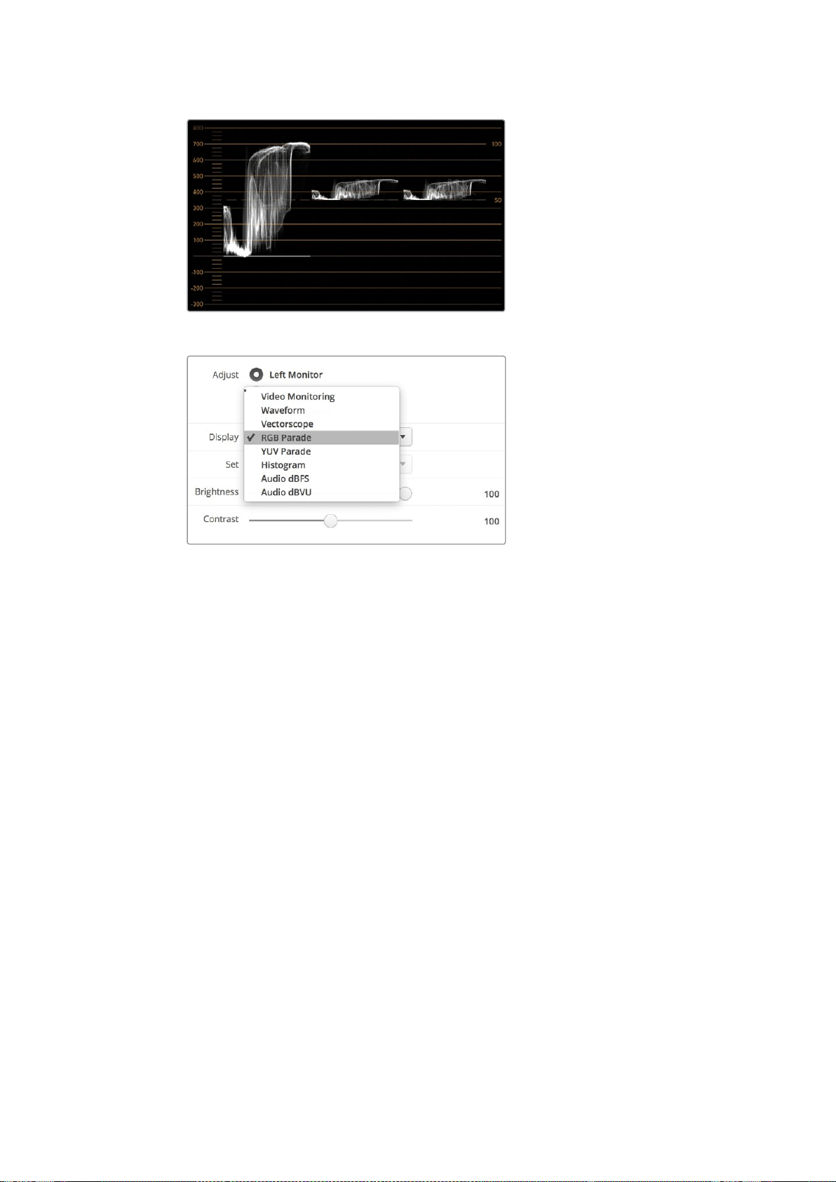
96Utiliser SmartScope Duo 4K
Affichage YUV Parade
Choisissez entre RBG Parade et YUV Parade dans le menu
déroulant Display du Blackmagic SmartView Setup.
Affichage Histogram
L'affichage Histogram est l'affichage le plus couramment utilisé par les graphistes et les cadreurs.
Ilmontre la distribution des tons clairs et foncés et vous permet de vérifier à quelle distance de la
ligne d'écrêtage ils se trouvent. L'affichage Histogram vous permet également de visualiser les
effets causés par les modifications de gamma dans votre vidéo.
Les tons sombres sont situés à gauche de l'affichage et les tons clairs se trouvent à droite. Toute la
vidéo devrait normalement se trouver entre les lignes 0% et 100% de l'histogramme. Votre vidéo
sera écrêtée si elle se situe en-dessous de 0% ou au-dessus de 100%. L'écrêtage vidéo est une
chose à éviter à tout prix lors du tournage, car les détails des tons foncés et des tons clairs doivent
être préservés si vous désirez par la suite effectuer de la correction colorimétrique en studio. Lors
du tournage, gardez la vidéo au-dessus de la ligne d'écrêtage des tons foncés et au-dessous de
celle des tons clairs. Cela vous donnera plus de liberté ultérieurement pour ajuster les couleurs sans
que les tons clairs et foncés aient l'air uniformes et manquent de détails.
Pendant la phase de correction colorimétrique, vous pouvez décider d’écrêter la vidéo. Dans ce
cas-là, l'affichage Histogram vous permettra de visualiser les effets de l'écrêtage sur la vidéo et vous
indiquera ce qui a été écrêté. Vous pouvez également utiliser le gamma pour créer un rendu
similaire, avec moins d'écrêtage et en conservant plus de détails.
L'affichage Histogram ne vous permet pas de vérifier s'il y a des niveaux de couleurs illégaux, mais
ilvous permet de visualiser les valeurs illégales dans les tons clairs et les tons foncés. Cet affichage
ne montre pas les couleurs, c'est pourquoi, même s'il n'affiche que des niveaux légaux, votre vidéo
peut quand même contenir des couleurs illégales. Comme mentionné précédemment, l'affichage
RGB Parade est le meilleur moyen de vérifier la présence de niveaux illégaux, car il les affiche à la
fois dans les éléments en couleurs et dans les éléments de luminance du signal vidéo.

97Utiliser SmartScope Duo 4K
L’affichage Histogram montre la distribution des
tons clairs et des tons foncés.
Sélectionnez Histogram dans le menu déroulant Display
du Blackmagic SmartView Setup.
Affichages des niveaux audio
Les affichages des niveaux audio vous indiquent les niveaux de l'audio intégré au signal vidéo SDI.
Jusqu’à 16 canaux d'audio intégré sont isolés puis affichés au format dBVU ou dBFS.
Le vumètre indique les niveaux moyens du signal, il est simple d'utilisation et très fréquemment
utilisé sur du matériel plus ancien. Le standard VU est calibré à partir de la recommandation de la
SMPTE suivante : une tonalité de test de 1 kHz est réglée à -20 dBFS.
Le dBFS est une mesure de l'ensemble du signal audio numérique. On le retrouve fréquemment
surle matériel numérique moderne.
Le scope audio de droite peut afficher deux canaux audio que vous pouvez sélectionner dans le menu
déroulant Set, par ex. ch 1 & 2, ch 3 & 4 etc. Le scope audio présente l'audio en mode X-Y afin que
vous puissiez voir les problèmes de balance audio et de déphasage. Il vous indique également si une
piste audio est mono ou stéréo. L'audio mono devrait apparaître en tant que ligne unique, verticale et
"en phase". Si la ligne est horizontale, votre audio est déphasé et il se peut qu'il soit annulé (perte
d'audio) lorsqu'il est reçu par du matériel en aval. Les erreurs de phase audio sont les erreurs les plus
courantes sur les grandes installations où les câbles ne sont pas toujours connectés convenablement.
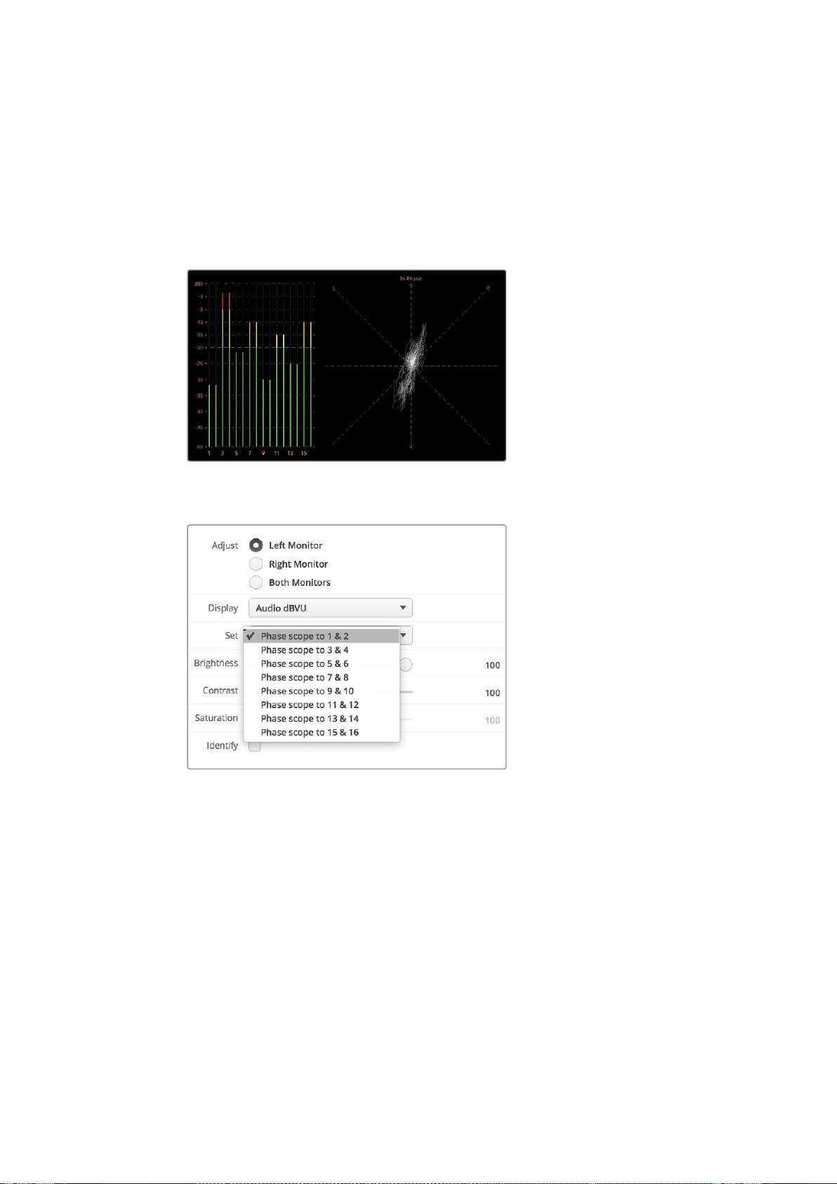
98Connexion à un réseau
Lors du monitoring de signaux stéréo, la ligne du scope audio de droite s'étend pour représenter
ladifférence entre les canaux audio gauche et droit. Plus la piste audio contient de son stéréo,
plusla ligne prendra une forme circulaire. Lorsque l'audio ne contient qu'un peu de contenu stéréo,
l'affichage est concentré autour de l'axe vertical.
L’audio représentant du dialogue apparaît généralement en tant que ligne verticale, tandis que la
musique qui contient du son stéréo renfle le scope. En effet, le son mono (L+R) s’affiche sur un axe
vertical, alors que le son stéréo (L-R) s’affiche sur un axe horizontal.
Affichage des niveaux audio indiquant des
niveaux de crête ainsi que la balance audio.
Affichage des niveaux audio indiquant des
niveaux de crête ainsi que la balance audio.
Connexion à un réseau
Si vous souhaitez ajuster à distance les paramètres de plusieurs appareils SmartView et
SmartScope, vous pouvez les connecter à un réseau.
Bien que les moniteurs SmartView et SmartScope affichent la vidéo sans devoir être configurés,
ilfaudra quand même régler les paramètres réseau. La configuration réseau peut seulement être
effectuée à l’aide d’une connexion USB directe à un ordinateur.

99Connexion à un réseau
Connexion Ethernet directe
La configuration à distance du moniteur peut être effectuée à l’aide d’une connexion Ethernet
directe à un ordinateur. Aucun commutateur réseau n’est requis, ce qui est pratique si vous devez
installer rapidement votre équipement. Des appareils supplémentaires peuvent être reliés en chaîne
à l’aide de la connexion Ethernet en boucle active de chaque appareil. Pour cela, tous les appareils
de la chaîne doivent être alimentés.
Si vous souhaitez connecter plusieurs appareils sans utiliser les adresses IP de votre réseau,
ousivous n’avez pas de réseau, il suffit de les connecter directement au port Ethernet de votre
ordinateur. C’est une manière rapide de connecter des appareils SmartView et SmartScope via
Ethernet, car il n’est pas nécessaire de relier des câbles à un commutateur réseau.
Connexion Ethernet
Commutateur réseau Ethernet
Si vous souhaitez connecter plusieurs appareils au réseau de votre studio, il suffit de brancher un
appareil SmartView ou SmartScope au commutateur réseau. Les autres appareils peuvent être reliés
en chaîne à l’aide de la connexion en boucle Ethernet active de chaque appareil afin de n’utiliser
qu’un seul port de votre commutateur. Ainsi, vous n’aurez pas besoin de relier plusieurs câbles au
commutateur réseau. Pour que cela fonctionne, tous les appareils de la chaîne doivent être alimentés.
Lorsque vous connectez des appareils à un commutateur réseau, vous pouvez modifier leurs
paramètres à partir de tous les ordinateurs du réseau. Il est également possible de modifier des
paramètres à partir d’un ordinateur portable Mac ou Windows via une connexion WiFi si votre réseau
comprend un point d’accès wireless.
Suivez ces étapes pour connecter un SmartView ou un SmartScope à un réseau IP local.
1 Connectez et alimentez l’appareil.
2 Connectez l’appareil à un commutateur réseau, ou directement à un ordinateur à l’aide
d’uncâble Ethernet RJ45 standard.
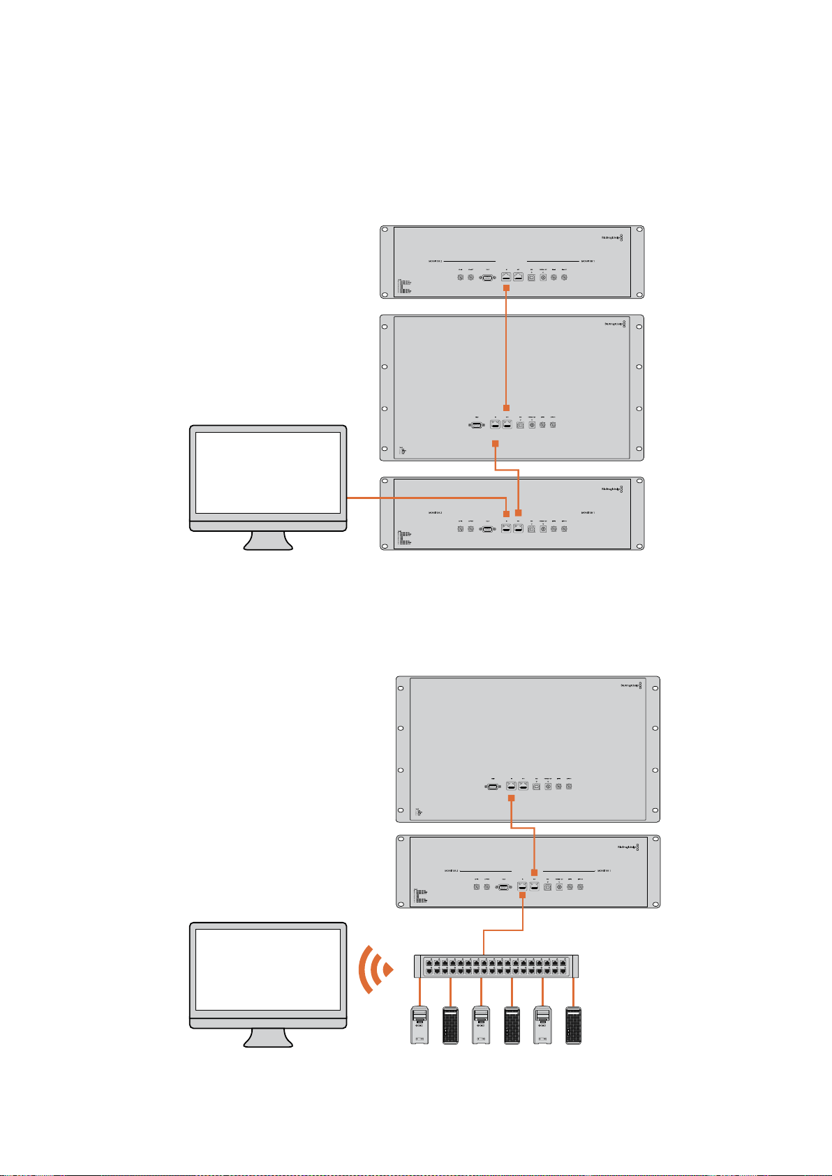
100Connexion à un réseau
Schéma de connexion Ethernet directe
Vous pouvez connecter le port Ethernet d’un ordinateur directement à l’appareil sans commutateur
réseau. Les appareils supplémentaires peuvent être reliés en chaîne. Ainsi, vous n’aurez pas
besoinde relier plusieurs câbles à un commutateur réseau. Tous les appareils de la chaîne doivent
être alimentés.
SmartScope 4KDuo
Schéma de connexion avec un commutateur réseau Ethernet
Si vous souhaitez connecter plusieurs appareils au réseau de votre studio, il suffit de brancher un
appareil au commutateur réseau. Les autres appareils peuvent être reliés en chaîne. Ainsi, vous
n’aurez pas besoin de relier plusieurs câbles au commutateur réseau. Tous les appareils de la chaîne
doivent être alimentés.
SmartScope 4KDuo
Commutateur réseau
Ethernet
Ordinateurs
des clients

101Modifier les paramètres réseau
Modifier les paramètres réseau
Paramètres réseau
Nom de l'appareil
Il est judicieux de modifier le nom de votre moniteur afin que chaque appareil SmartView ou
SmartScope soit facile à identifier sur le réseau, par ex. «Caméras 1&2», «Sortie Multi View»,
«Flux 4K» etc.
Lorsque vous changez le nom du moniteur, veillez à ce que le moniteur soit connecté via USB ou
Ethernet. Lancez le Blackmagic SmartView Setup et cliquez sur l'icône de paramétrage situé sous
lenom du moniteur. Dans la page de paramétrage, cliquez sur Network et modifiez le nom de votre
moniteur dans la section Details. Si le nom choisi n’est pas valide, une icône d'avertissement
apparaîtra à côté du nom. Si le nom est valide, une coche verte s’affichera. Appuyez sur la touche
Retour de votre clavier pour confirmer le changement de nom.
Paramètres réseau
Pour apporter des changements aux paramètres réseau du Blackmagic SmartView Setup, votre
moniteur Blackmagic doit être branché à un ordinateur via USB. Les paramètres réseau ne peuvent
pas être modifiés via Ethernet.
Par défaut, le SmartView et le SmartScope utilisent le protocole DHCP pour obtenir automatiquement
une adresse IP à partir du réseau.
Si vous ne possédez pas de serveur DHCP, vous pouvez activer la fonctionnalité Partage Internet
de macOS, ou Partage de connexion Internet de Windows 8.1 ou Windows 10, afin de fournir des
adresses DHCP aux appareils en liaison directe. Cela vous évitera de devoir attribuer manuellement
des adresses IP statiques à chaque appareil. Vous pouvez utiliser cette fonctionnalité pour obtenir
des adresses DHCP, même si votre ordinateur ne possède pas de connexion Internet. Le partage
Internet est décrit dans les documents d’aide de macOS et de Windows 8.1 et 10.
Si le DHCP ne peut pas être utilisé dans votre configuration, choisissez une adresse IP statique.
Veuillez demander une adresse IP disponible à votre administrateur système afin d’éviter de créer
un conflit IP sur votre réseau. Vous devrez spécifier une adresse IP unique pour chaque appareil
SmartView et SmartScope ainsi qu’un masque de sous-réseau commun. Il n’est pas nécessaire de
changer la valeur par défaut du champ Passerelle à moins que vous ne souhaitiez connecter vos
appareils à une passerelle réseau, telle qu’un routeur.
Si aucun monitor SmartView ou SmartScope n’a été trouvé sur le réseau, il se peut que les appareils
n’aient pas reçu d’adresse IP via DHCP. Il faudra donc configurer manuellement chaque appareil
avec les paramètres réseau appropriés.
1 Connectez un moniteur SmartView ou SmartScope à votre ordinateur via USB et lancez le
logiciel Blackmagic SmartView Setup.
2 Le moniteur connecté s’affiche automatiquement sur la page d’accueil du SmartView Setup.
Une icône USB apparaît à côté de son nom.
3 Ajustez les paramètres réseau du moniteur.
4 Répétez ces étapes pour tous les appareils qui n’ont pas reçu d’adresse IP via DHCP.

102Modifier les paramètres réseau
L’icône USB située à côté du nom du moniteur indique que le moniteur
est connecté à votre ordinateur via USB. Pour modifier les paramètres
réseau, votre moniteur Blackmagic doit être connecté via USB.
Les paramètres réseau peuvent être réglés afin d’utiliser une adresse
IP DHCP ou statique. Ils ne peuvent être modifiés que via USB.
Ajouter un moniteur Blackmagic
Si vous connaissez l’adresse IP d’un SmartView ou d’un SmartScope Duo 4K mais qu’elle n’apparaît
pas automatiquement sur la page d’accueil du Blackmagic SmartView Setup, vous pouvez ajouter
cemoniteur manuellement. Pour ce faire :
1 Veillez à ce que le moniteur soit connecté via Ethernet. Cliquez sur l’icône + située au coin
gauche de la page d’accueil pour ouvrir la fenêtre permettant d’ajouter un moniteur Blackmagic.
2 Saisissez l'adresse IP du moniteur et cliquez sur Add.
3 Le logiciel vérifie la présence de l’appareil et l’ajoute aux moniteurs Blackmagic affichés sur
la page d’accueil du SmartView Setup. Cliquez sur la flèche droite pour voir le moniteur que
vous venez d’ajouter.
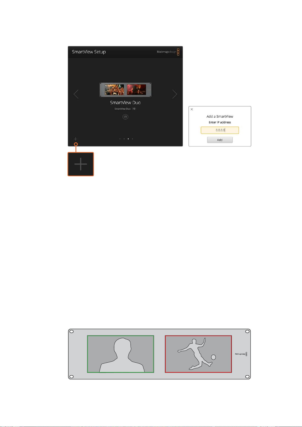
103Utilisation du tally
Vous pouvez ajouter manuellement un moniteur SmartView
ou SmartScope à la liste des moniteurs connectés en cliquant
sur l’icône + et en saisissant l’adresse IP du moniteur.
Utilisation du tally
Broches du port tally
Il n’est pas nécessaire de connecter le port tally du SmartView ou du SmartScope. Vous pouvez
donc ignorer cette section si vous ne souhaitez pas utiliser la fonctionnalité tally.
Chaque écran du SmartView ou du SmartScope intègre des bordures tally indépendantes rouges,
vertes, ou bleues. Elles peuvent être utilisées pour indiquer l’état d’un signal vidéo, par exemple
àl’antenne, en prévisualisation ou en cours d’enregistrement.
Le port tally D-sub à 9 broches accepte les signaux de fermeture de contact provenant de
mélangeurs et de systèmes d’automatisation. Veuillez consulter le schéma de brochage tally
ci-dessous pour obtenir des informations concernant le câblage du port tally afin de l’utiliser avec
unmélangeur ou un système d’automatisation.
La description du câblage du port D à 9 broches est imprimée à l’arrière de l’appareil. Elle indique
les fermetures de contact permettant d’afficher les bordures tally rouges, vertes ou bleues sur
chaque moniteur.
SmartView Duo affichant des bordures tally vertes et rouges.
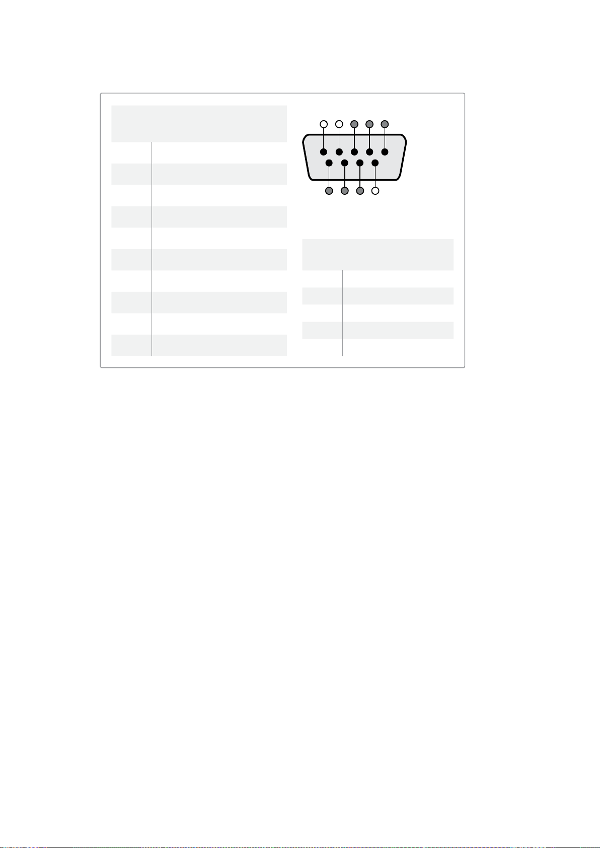
104Optimiser l'angle de vision
Optimiser l'angle de vision
Si le SmartView Duo, le SmartView HD ou le SmartScope doivent être installés dans la partie
supérieure d’un rack d’équipement, il se peut que vous souhaitiez inverser les écrans LCD pour
obtenir un angle de vision optimal. En cas d’inversion, les images des écrans LCD prendront
automatiquement l’orientation appropriée. Un tournevis Pozidriv 2 est requis pour déconnecter et
reconnecter la plaque frontale de l’assemblage arrière. Cette procédure est simple et ne demande
pas d’ouvrir l’assemblage arrière.
Les étapes suivantes décrivent comment inverser l’appareil tout en gardant le logo de Blackmagic
Design dans le bon sens sur la plaque frontale. Un tournevis Pozidriv 2 est requis.
1 Retirez les vis situées sur le haut, le bas, le côté gauche et le côté droit de la plaque
frontale. Le SmartView Duo et le SmartScope Duo 4K possèdent 10 vis, tandis que le
SmartView HD en possède 18.
2 Séparez la plaque frontale de l’assemblage arrière comme illustré ci-dessous.
3 Retournez l’assemblage arrière.
4 Réintégrez la plaque frontale à l’assemblage arrière.
5 Revissez les vis dans le châssis.
Votre SmartView ou SmartScope est maintenant prêt à être installé dans la partie supérieure d’un
rack. Une fois installé sur le rack, le SmartView affiche un angle de vision optimal même en cas de
secousses, car il ne possède pas de molettes ou de commandes externes qui pourraient se
dérégler ou se détacher.
SmartView Duo ou SmartScope Duo 4K
Broches tally
Broche Fonction
1 Moniteur 1 Rouge
2 Moniteur 1 Vert
3 Moniteur 1 Bleu
4 Masse
5 Masse
6 Masse
7 Moniteur 2 Rouge
8 Moniteur 2 Vert
9 Moniteur 2 Bleu
SmartView HD ou SmartView 4K
Broches tally
Broche Fonction
1 Rouge
2 Vert
3 Bleu
4 Masse
5 4 3 2 1
9 8 7 6
Port tally du SmartView


106Developer Information
Developer Information
Developing Custom Software Using Blackmagic Design Hardware
The Blackmagic SmartView Ethernet Protocol allows developers to remotely control Blackmagic
SmartView and SmartScope hardware with their own custom software. The Blackmagic
SmartView Ethernet Protocol is a text-based status and control protocol.
Downloading the Free SmartView EthernetProtocol
The Blackmagic SmartView Ethernet Protocol is free. It is included in this SmartView &
SmartScope manual and can be downloaded from http://www.blackmagicdesign.com/support/
Joining the Blackmagic Design Developer List
The Blackmagic Developer mailing list is designed for technical questions regarding
technologies used by Blackmagic Design, e.g., QuickTime, Core Media, DirectShow, codecs,
APIs, SDKs, etc. The free mailing list is a forum where developers can discuss ideas and
problems with other developers. Any subscriber may reply and the Blackmagic Design
engineers may also respond when appropriate. You can subscribe to the mailing list at:
http://lists.blackmagicdesign.com/mailman/listinfo/bmd-developer
In some cases, we might request a brief outline of the software you are developing if it is not
immediately obvious from your domain name that your organization develops video software.
Please don’t take offence as we’re simply trying to keep the list free of spam and viruses as well
as end-user customers asking non-development questions, employment agents or sales
people trying to promote products on the list. The list is just for developers.
Contacting Blackmagic Design DeveloperAssistance
You can also contact us via developer@blackmagicdesign.com if you have any developer
related questions or wish to ask questions off the list.
Blackmagic 2K Format – Overview
Blackmagic Design products support 3G-SDI video, which allows twice the data rate of
traditional HD-SDI video. We thought it would be a really nice idea to add 2K film support,
via 3G-SDI technology, so we could simplify feature film workflows. With the popularity of
Blackmagic Design editing systems worldwide, now thousands of people can benefit from
a feature film workflow revolution.
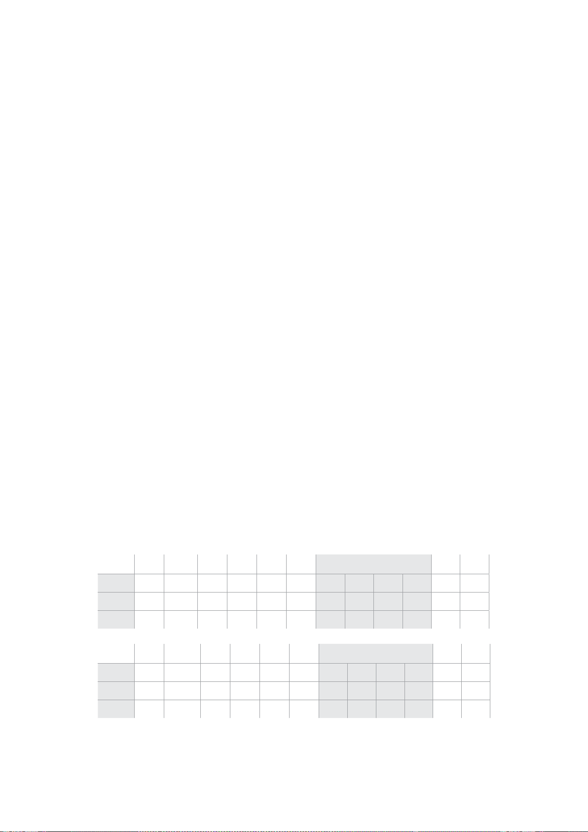
107Developer Information
This information includes everything product developers need to know for building native
2KSDI equipment. Of course, all Blackmagic products can be updated, so if the television
industry adopts an alternative SDI-based film standard, we can add support for that too!
Frame Structure
Transmitted at 23.98, 24 or 25 frames per second as a Progressive Segmented Frame.
Active video is 2048 pixels wide by 1556 lines deep.
Total lines per frame : 1650
Active words per line are 1535. One word consists of a 10-bit sample for each of the
four data streams, i.e., a total of 40 bits. See the diagram named Blackmagic 2K Format
- Data Stream Format.
Total active lines : 1556
Total words per line : 1875 for 23.98/24Hz and 1800 for 25Hz.
Fields per frame : 2, 825 lines each
Active lines located on lines 16-793 (field 1) and 841-1618 (field 2).
Transport Structure
Based on SMPTE 372M Dual Link mapping and SMPTE 425M-B support for mapping
SMPTE 372M into a single 3 Gb/s link.
Timing reference signals, line number and line CRC insertion is the same as above.
During active video, 10-bit Red, Green and Blue data is sent in the following sequence:
Optional ancillary data is inserted into both virtual interfaces.
At present, only audio data is included: as per standard HD audio insertion (SMPTE
S299M) the audio data packets are carried on data stream two and audio control
packets are carried on data stream one.
Data stream 1: Green_1, Green_2, Green_3, Green_5...Green_2047
Data stream 2: Blue_1, Blue_2, Green_4, Blue_5...Green_2048.
Data stream 3: Red_1, Blue_3, Blue_4, Red_5...Blue_2048.
Data stream 4: Red_2, Red_3, Red_4, Red_6...Red_2048.
Blackmagic 2K Format – Vertical Timing Reference
This diagram shows the vertical timing details with line numbers and Field, Vertical and
Horizontal bits for the Timing Reference Signal codes.
Field 1 Active
F 1 0 0 0 0 0 0 0 0 0 0 0
V 1 1 1 1 1 1 0 0 0 0 1 1
LINE # 1650 1 2 ... 14 15 16 ... 792 793 ... 825
Field 2 Active
F 0 1 1 1 1 1 1 1 1 1 1 1
V 1 1 1 1 1 1 0 0 0 0 1 1
LINE # 825 826 827 ... 839 840 841 ... 1617 1618 ... 1650
108Developer Information
Blackmagic 2K Format – Data Stream Format
This diagram shows the data stream formats around the optional ancillary data section of the
horizontal line. Note that each active pixel takes up three samples.
Data Stream 1
G2041
G2042
G2043
G2045
G2046
G2047
EAV(3FFh)
EAV(000h)
EAV(000h)
EAV(XYZh)
LN0
LN1
CRC0
CRC1
ANC/Audio
Data
SAV(3FFh)
SAV(000h)
SAV(000h)
SAV(XYZh)
G1
G2
G3
G5
Data Stream 2
B2041
B2042
G2044
B2045
B2046
G2048
EAV(3FFh)
EAV(000h)
EAV(000h)
EAV(XYZh)
LN0
LN1
CRC0
CRC1
ANC/Audio
Data
SAV(3FFh)
SAV(000h)
SAV(000h)
SAV(XYZh)
B1
B2
G4
B5
Data Stream 3
R2041
B2043
B2044
R2045
B2047
B2048
EAV(3FFh)
EAV(000h)
EAV(000h)
EAV(XYZh)
LN0
LN1
CRC0
CRC1
040
…
040
SAV(3FFh)
SAV(000h)
SAV(000h)
SAV(XYZh)
R1
B3
B4
R5
Data Stream 4
R2042
R2043
R2044
R2046
R2047
R2048
EAV(3FFh)
EAV(000h)
EAV(000h)
EAV(XYZh)
LN0
LN1
CRC0
CRC1
200
…
200
SAV(3FFh)
SAV(000h)
SAV(000h)
SAV(XYZh)
R2
R3
R4
R6
Word#
23.98/24 PsF
1870
1871
1872
1873
1874
1875
1
2
3
4
5
6
7
8
9
…
335
336
337
338
339
340
341
342
343
Word#
25 PsF
1795
1796
1797
1798
1799
1800
1
2
3
4
5
6
7
8
9
…
260
261
262
263
264
265
266
267
268

109Developer Information
Blackmagic SmartView Ethernet Protocol v1.3
Summary
The Blackmagic SmartView Ethernet Protocol is a text-based status and control protocol, very
similar in structure to the Videohub protocol, that is accessed by connecting to TCP port 9992
on a SmartView or SmartScope device.
Upon connection, the SmartView or SmartScope device sends a complete dump of the state
of the device. After the initial dump, state changes are sent asynchronously.
The device sends information in blocks which have an identifying header, followed by a colon.
A block can span multiple lines and is terminated by a blank line.
To be resilient to future protocol changes, clients should ignore blocks they do not recognize,
up to the trailing blank line. Within recognized blocks, clients should ignore lines they do not
recognize.
Version 1.3 of the Blackmagic SmartView Ethernet
Protocol was released with SmartView 1.3 software.
Protocol Preamble
The first block sent by the SmartView Server is always the protocol preamble:
PROTOCOL PREAMBLE:
↵
Version: 1.3
↵
↵
The version field indicates the protocol version. When the protocol is changed in a compatible
way, the minor version number will be updated. If incompatible changes are made, the major
version number will be updated.
Device Information
The next block contains general information about the connected SmartView or SmartScope
device.
SMARTVIEW DEVICE:
↵
Model: SmartView Duo
↵
Hostname: stagefront.studio.example.com
↵
Name: StageFront
↵
Mo nitor s: 2
↵
Inverted: false
↵
↵
This example shows the output for a SmartView Duo device, which has two LCDs.
The INVERTED flag indicates whether the device has detected that it has been mounted in an
inverted configuration to optimize LCD viewing angle.
Legend
↵
carriage return
… and so on

110Developer Information
Network Configuration
The next block shows the TCP/IP networking configuration:
NETWORK:
↵
Dynamic IP: true
↵
Static address: 192.168.2.2
↵
St atic netm as k: 255.255.255.0
↵
St atic gatew ay: 192.168.2.1
↵
C u rr e nt ad d r e ss: 192.168.1.101
↵
C u rr e nt netm a sk: 255.255.255.0
↵
C u rr e nt g ate w ay: 192.168.1.1
↵
↵
The network settings prefixed with CURRENT show the active TCP/IP settings, and are read-
only. The CURRENT settings reflect either the DHCP or Static configuration, depending on the
DYNAMIC IP flag.
Changing Networking Settings
The network can be configured to use either DHCP or a static configuration. To enable DHCP:
NETWORK:
↵
Dynamic IP: true
↵
↵
To set a fixed IP address, supply all static parameters, thus:
NETWORK:
↵
Dynamic IP: false
↵
Static address: 192.168.2.2
↵
St atic netm as k: 255.255.255.0
↵
St atic gatew ay: 192.168.2.1
↵
↵
The parameters with the CURRENT prefix are read-only, and show the active configuration,
regardless of the static or dynamic setting.
Changing the device name, or any network settings, will cause the IP connection to be
dropped. The device will restart its networking and advertise its new name on the network.
Changing Monitor Settings
The display settings for each monitor are specified individually. One or more parameters can
be modified at the same time and multiple settings can be supplied in one block.
The valid range for numeric values is 0-255. The CONTRAST and SATURATION properties are
zero-centered, so the normal value is 127, such that the displayed picture is the same as the
original. A value greater than 127 in either channel will cause the contrast or saturation to be
increased, and similarly a value less than 127 will cause a decrease.
For example, to set the brightness to 50% and desaturate the image to Black & White:
MONITOR A:
↵
Brightness: 127
↵
Saturation: 0
↵
↵

111Developer Information
Displaying SD in 16:9
The following command sets standard definition video to display in 16:9:
MONITOR A:
↵
WidescreenSD: ON
↵
Displaying SD in 4:3
The following command sets standard definition video to display in 4:3:
MONITOR A:
↵
WidescreenSD: OFF
↵
Identification and Tally Settings
The Identify flag is transient, and will cause a white border to be displayed around the entire
picture for a duration of 15 seconds, after which it will be reset. This feature is primarily aimed at
identifying which monitor is currently being configured when it is mounted in a rack comprising
multiple units. To turn on:
MONITOR A:
↵
Ide ntify: tr u e
↵
↵
The IDENTIFY border will temporarily override any other border setting in effect.
The BORDER property can be used to programmatically set the soft Tally colored borders to
one of the primary colors: RED, GREEN, BLUE, WHITE or NONE. This setting can be overridden
by the electrical Tally signals at the DB-9 input on the device itself. For example, to set the soft
Tally to green:
MONITOR B:
↵
Border: green
↵
↵
The hard wired tally will always override the soft tally. The full state report will always show the
current valid border.
SmartScope Settings
On SmartScope Duo 4K, each monitor can be set to display a different scope. The values for
activating specific scopes are mapped as follows:
AudioDbfs
AudioDbvu
Histogram
ParadeRGB
ParadeYUV
Picture (This is the same as Video Monitor)
Vector100
Vector75
WaveformLuma
MONITOR A:
↵
ScopeMode: Picture
↵
↵
In the example above, Monitor A has been set as a video monitor.

112Developer Information
Displaying SD in 16:9
The set Video Monitor mode to display standard definition video in 16:9:
MONITOR A:
↵
ScopeMode: Picture
↵
WidescreenSD: ON
↵
Displaying SD in 4:3
To set Video Monitor mode to display standard definition video in 4:3:
MONITOR A:
↵
ScopeMode: Picture
↵
WidescreenSD: OFF
↵
When setting one of SmartScope Duo 4K’s monitors to audio metering, you can also select
which channels to show. The values for selecting which audio channels are mapped in the
following way:
0: Channels 1 and 2
1: Channels 3 and 4
2: Channels 5 and 6
3: Channels 7 and 8
4: Channels 9 and 10
5: Channels 11 and 12
6: Channels 13 and 14
7: Channels 15 and 16
MONITOR B:
↵
ScopeMode: AudioDbvu
↵
AudioChannel: 0
↵
↵
In the example above, Monitor B has been selected to display Audio Metering in Dbvu with
audio channels 1 and 2 selected for the phase meter.
Selecting LUTs for SmartView 4K
To select 3D LUTs using SmartView 4K:
MONITOR A:
↵
LUT: 0 LUT 1
1 LUT 2
NONE DISABLE
↵
↵

113Assistance
Assistance
Obtenir de l'assistance
Il y a quatre façons d’obtenir de l’assistance :
1 Consulter le centre d'assistance technique de Blackmagic Design à l’adresse
www.blackmagicdesign.com/fr/support pour obtenir les dernières informations de support
technique.
2 Contacter votre revendeur Blackmagic Design.
Votre revendeur possède les dernières mises à jour techniques de Blackmagic Design
etdevrait pouvoir vous aider immédiatement. Nous vous recommandons également de
considérer les options de support offertes par votre revendeur, car il peut proposer une
solution adaptée aux exigences de votre workflow.
3 Vous pouvez aussi nous envoyer un email à l’aide du bouton «Envoyer un email»
delapage d’assistance : www.blackmagicdesign.com/fr/support
4 Contacter le service d'assistance de Blackmagic Design par téléphone. Vous pouvez
trouver le centre d’assistance le plus proche de chez vous en cliquant sur le bouton
« Trouver un support technique » sur la page d’assistance de Blackmagic Design.
Donnez-nous autant d’informations que possible concernant votre problème technique et les
spécifications du système afin que nous puissions y répondre le plus rapidement possible.

114Avertissements et informations desécurité
Avertissements et informations
desécurité
Avertissements
Élimination des déchets d'équipements électriques et électroniques au sein
del'Unioneuropéenne.
Le symbole imprimé sur ce produit indique qu'il ne doit pas être jeté avec les autres
déchets. Cet appareil doit être déposé dans un point de collecte agréé pour être
recyclé. La collecte individuelle et le recyclage de votre équipement permettra de
préserver les ressources naturelles et garantit un recyclage approprié afin d'éviter la
contamination de l'environnement par des substances dangereuses pour la santé.
Pourplus d'informations quant aux lieux d'éliminations des déchets d'équipements
électriques, vous pouvez contacter votre mairie ou le service local de traitement des
ordures ménagères.
Cet équipement a été testé et déclaré conforme aux limites imposées aux appareils
numériques de classe A, en vertu du chapitre 15 des règles de la FCC. Ces limites ont
pour objectif d'assurer une protection suffisante contre les interférences nuisibles
lorsque l'équipement est utilisé dans un environnement commercial. Cet équipement
génère, utilise et peut dégager de l'énergie de radiofréquence et, s'il n'est pas installé
et utilisé conformément aux manuel d'utilisation, peut provoquer un brouillage
préjudiciable aux communications radio. L'utilisation de cet équipement en zone
résidentielle est susceptible de provoquer des interférences nuisibles, auquel cas il
sera demandé à l'utilisateur de corriger ces interférences à ses frais.
L'utilisation de cet appareil est soumise aux deux conditions suivantes :
1 Cet appareil ne doit pas causer d'interférences nuisibles.
2 Cet appareil doit accepter toute interférence reçue, notamment celles pouvant
entraîner un dysfonctionnement.
Informations de sécurité
Cet appareil doit être connecté à une prise secteur équipée d'un conducteur de protection.
Afin de réduire le risque de décharge électrique, ne pas éclabousser ou renverser de
liquide sur cet appareil.
Cet appareil peut être utilisé dans un climat tropical lorsque la température ambiante
n'excède pas 40ºC.
Veillez à ce que l'espace autour du produit soit suffisant afin de ne pas compromettre
laventilation.
Lorsque vous installez l'appareil sur rack, veillez à ce que la ventilation ne soit pas
compromise par les autres équipements.
Les pièces de cet appareil ne sont pas réparables par l'opérateur. Toute réparation/
opération d'entretien doit être effectuée par un centre de service Blackmagic Design.
Cet appareil ne peut être utilisé qu'à une altitude inférieure à 2000 mètres.
Vous pouvez connecter des modules SFP fibre optique à ce produit. Utilisez seulement des
modules SFP équipés de lasers de classe 1.
Modules SFP Blackmagic Design recommandés:
3G-SDI : PL-4F20-311C
6G-SDI : PL-8F10-311C
115Garantie
Avertissement destiné aux techniciens agréés
Assurez-vous que le courant des deux prises est bien coupé avant toute opération
d'entretien.
Attention - Système de fusibles bipolaire/neutre
La source d'alimentation de cet appareil contient un fusible dans les conducteurs
de ligne et neutre. Elle est compatible avec le système de distribution électrique/
réseau de distribution d'électricité en Norvège.
Garantie
Garantie limitée à 12 mois
Par la présente, Blackmagic Design garantit que ce produit sera exempt de défauts matériels et
defabrication pendant une durée de un an à compter de la date d'achat. Si un produit s’avère
défectueux pendant la période de garantie, Blackmagic Design peut, à sa seule discrétion, réparer
le produit défectueux sans frais pour les pièces et la main d’œuvre, ou le remplacer.
Pour se prévaloir du service offert en vertu de la présente garantie, il vous incombe d’informer
Blackmagic Design de l’existence du défaut avant expiration de la période de garantie, et de
prendre les mesures nécessaires pour l’exécution des dispositions de ce service. Le consommateur
a la responsabilité de s’occuper de l’emballage et de l'expédition du produit défectueux au centre
de service nommément désigné par Blackmagic Design, en frais de port prépayé. Il incombe au
Consommateur de payer tous les frais de transport, d’assurance, droits de douane et taxes et toutes
autres charges relatives aux produits qui nous auront été retournés et ce quelle que soit la raison.
La présente garantie ne saurait en aucun cas s’appliquer à des défauts, pannes ou dommages
causés par une utilisation inappropriée ou un entretien inadéquat ou incorrect. Blackmagic Design
n’a en aucun cas l’obligation de fournir un service en vertu de la présente garantie : a) pour réparer
les dommages résultant de tentatives de réparations, d’installations ou tous services effectués par
du personnel non qualifié par Blackmagic Design, b) pour réparer tout dommage résultant d'une
utilisation inadéquate ou d'une connexion à du matériel incompatible, c) pour réparer tout dommage
ou dysfonctionnement causé par l’utilisation de pièces ou de fournitures n’appartenant pas à la
marque de Blackmagic Design, d) pour examiner un produit qui a été modifié ou intégré à d’autres
produits quand l’impact d’une telle modification ou intégration augmente les délais ou la difficulté
d’examiner ce produit. CETTE GARANTIE REMPLACE TOUTE GARANTIE EXPLICITE OU IMPLICITE.
BLACKMAGIC DESIGN ET SES REVENDEURS DÉCLINENT EXPRESSÉMENT TOUTE GARANTIE
IMPLICITE DE COMMERCIALISATION OU D'ADAPTATION DANS QUELQUE BUT QUE CE SOIT.
LARESPONSABILITÉ DE BLACKMAGIC DESIGN POUR RÉPARER OU REMPLACER UN PRODUIT
S'AVÉRANT DÉFECTUEUX CONSTITUE LA TOTALITÉ ET LE SEUL RECOURS EXCLUSIF PRÉVU ET
FOURNI AU CONSOMMATEUR POUR TOUT DOMMAGE INDIRECT, SPÉCIFIQUE, ACCIDENTEL OU
CONSÉCUTIF, PEU IMPORTE QUE BLACKMAGIC DESIGN OU SES REVENDEURS AIENT ÉTÉ
INFORMÉS OU SE SOIENT RENDUS COMPTE AU PRÉALABLE DE L'ÉVENTUALITÉ DE CES
DOMMAGES. BLACKMAGIC DESIGN NE PEUT ÊTRE TENU POUR RESPONSABLE DE TOUTE
UTILISATION ILLICITE OU ABUSIVE DU MATÉRIEL PAR LE CONSOMMATEUR. BLACKMAGIC
DESIGN N'EST PAS RESPONSABLE DES DOMMAGES RÉSULTANT DE L'UTILISATION DE CE
PRODUIT. LE CONSOMMATEUR MANIPULE CE PRODUIT À SES SEULS RISQUES.
© Copyright 2018 Blackmagic Design. Tous droits réservés. 'Blackmagic Design’, ‘DeckLink’, ‘HDLink’, ‘Workgroup Videohub’,
‘Multibridge Pro’, ‘Multibridge Extreme’, ‘Intensity’ et ‘Leading the creative video revolution’ sont des marques déposées aux
USA et dans d'autres pays. Tous les autres noms de société et de produits peuvent être des marques déposées de leurs
sociétés respectives auxquelles ils sont associés.


Willkommen!
Wir träumen von einer Entwicklung der Fernsehbranche zu einer echten Kreativbranche, die
jedermann Zugriff auf Video in höchster Qualität gewährt. Wir hoffen, Sie teilen diesen Traum
mit uns und wünschen Ihnen in diesem Sinne kreatives Schaffen.
Videomonitoring ist ein Muss in jeder Einrichtung. Da kommt der SmartView 4K mit seinem
integrierten LCD in 4K-Auflösung genau richtig. Denn mit ihm können Sie Ultra-HD-Video in
Vollauflösung überprüfen. Und dank seines eleganten Rack-Gehäuses mit 6HE lassen sich
Einstellungen in Windeseile ändern. Der SmartView HD wartet mit einem unglaublichen 17Zoll
großen LCD in einem ebenfalls 6HE hohen Gehäuse auf und ist weniger als einen Zoll tief. Der
SmartView Duo hingegen kommt mit zwei komplett voneinander unabhängigen 8-Zoll-LCDs
in einem drei Rackeinheiten hohen Gehäuse und ist ebenfalls weniger als einen Zoll tief. Das
Modell SmartScope Duo 4K bietet neben zwei unabhängigen 8-Zoll-LCDs eine Waveform-
Funktionalität. Damit haben Sie Ihre Videopegel immer im Auge. Alle SmartView Monitore
unterstützen Video in SD, HD und 2K über 3G-SDI. Der SmartScope Duo 4K und der SmartView
4K unterstützen darüber hinaus Ultra HD 4K über 6G-SDI bzw. 12G-SDI.
Das Videomonitoring mit Produkten dieser Familie ist auf der Stelle einsatzbereit: auspacken,
anschließen, fertig! Mit der Blackmagic SmartView Setup Software bekommen Nutzer
außerdem ein leicht verständliches und intuitives Konfigurations-Tool in die Hand.
Diese Bedienungsanleitung enthält alle nötigen Informationen zur Installation Ihres Blackmagic
SmartView und SmartScope. Wenn Sie jedoch Fragen zu IP-Adressen oder Computer-
Netzwerken haben, wenden Sie sich bitte an einen technischen Berater. SmartViews und
SmartScopes sind einfach zu installieren, allerdings sind anschließend einige Voreinstellungen
vorzunehmen, die technisch etwas anspruchsvoller sind.
Unserer Einschätzung nach sollte die komplette Installation nicht mehr als rund 5 Minuten
dauern. Besuchen Sie die Support-Seiten auf unserer Website unter www.blackmagicdesign.
com/de/support und laden Sie dort die neueste Version dieses Handbuchs und der Software
herunter. Bitte registrieren Sie beim Herunterladen der Software Ihr Gerät, damit wir Sie über
Software-Aktualisierungen informieren können. Wir arbeiten ständig an neuen Features und
Verbesserungen und würden uns über Ihr Feedback freuen!
Grant Petty
CEO, Blackmagic Design

Inhaltsverzeichnis
SmartView & SmartScope
Erste Schritte 119
SmartView und SmartScope 119
Anschließen von Videoquellen 120
Anschließen Ihres Computers 120
Blackmagic SmartView Setup installieren 121
Blackmagic SmartView SetupimEinsatz 122
Aktualisieren der Software 122
Anpassen der Monitoreinstellungen 122
Der SmartView 4K im Einsatz 125
Der Blackmagic SmartView 4K 125
Bedientasten 126
3D-LUTs mit Blackmagic SmartView Setup laden 128
Der SmartScope Duo 4K im Einsatz 129
Was ist der Blackmagic SmartScope? 129
Die Video-Monitoring-Anzeige 129
Waveform-Anzeige 130
Vektorskop-Anzeige 131
Parade-Anzeige 133
Histogramm-Anzeige 134
Audiopegelmeter-Anzeige 135
Anschließen an ein Netzwerk 136
Direkte Ethernet-Verbindung 137
Ethernet-Netzwerk-Switch 137
Anpassen von Netzwerkeinstellungen 139
Netzwerkeinstellungen 139
Hinzufügen eines Blackmagic Monitors 140
Arbeiten mit Tally 141
Pinbelegung des Tally-Ports 141
Optimieren des Betrachtungswinkels 142
Informationen für Entwickler (Englisch) 144
Blackmagic 2K Format – Overview 144
Blackmagic 2K Format – Vertical Timing Reference 145
Blackmagic 2K Format – DataStream Format 146
Blackmagic SmartView Ethernet Protocol v1.3 147
Hilfe 151
Gesetzliche Vorschriften undSicherheitshinweise 152
Garantie 153
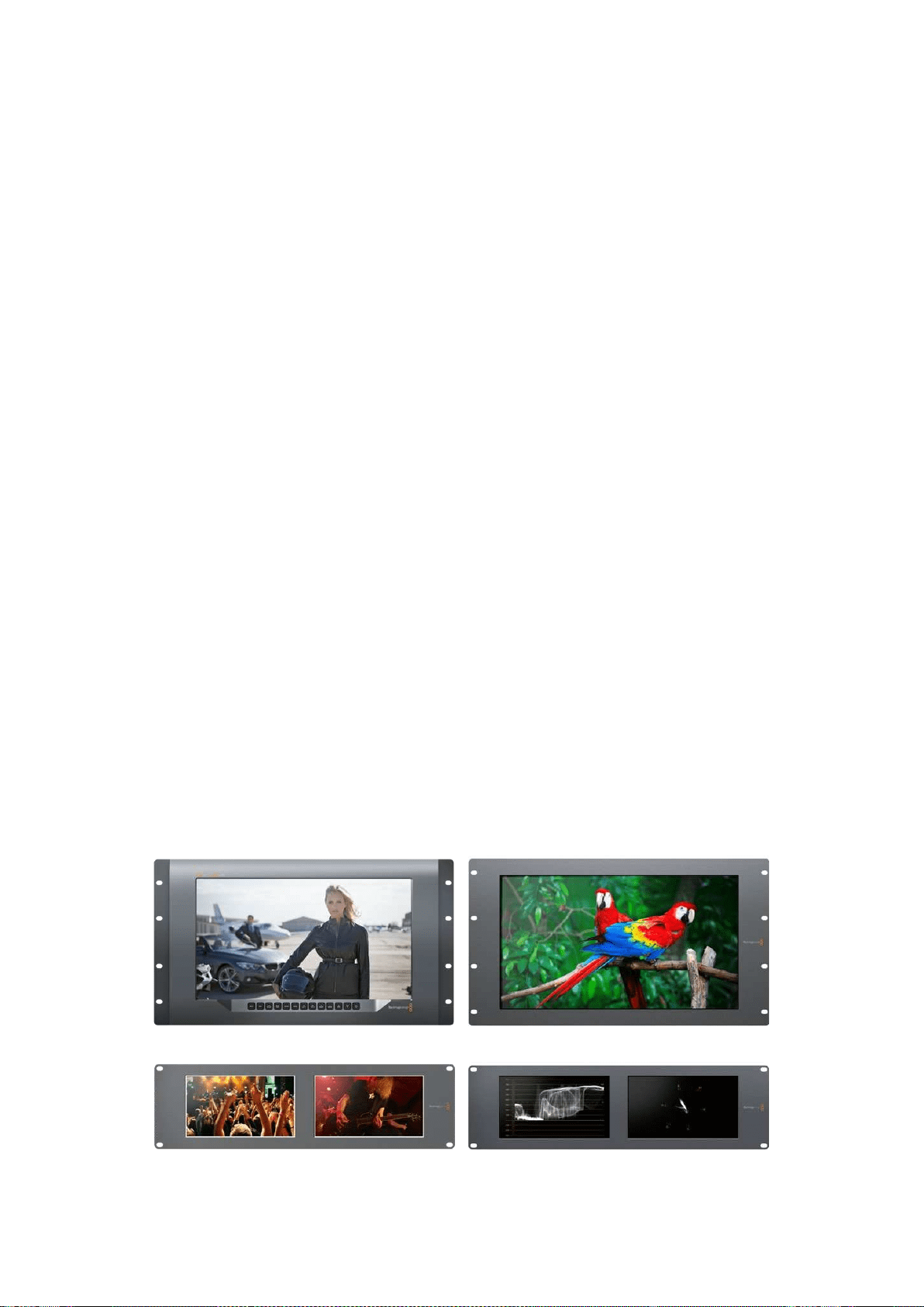
119Erste Schritte
Erste Schritte
SmartView und SmartScope
SmartView Monitore eignen sich perfekt für alle Einrichtungen mit rackbasierter Bildkontrolle.
Versorgen Sie Ihren SmartView zum Einstieg lediglich mit Strom und schließen Sie eine SDI-Quelle an.
Das Modell SmartView 4K hat ein 15,6Zoll großes LCD, auf dem Sie SD-, HD- und Ultra-HD-Video in
seiner nativen Pixelauflösung von 3840x2160 kontrollieren können. Über die Tasten auf dem
Frontbedienfeld können Sie spielend leicht Eingänge auswählen, die Helligkeit des Bildschirms
anpassen, den blauen Kanal auf Rauschen überprüfen, Informationen zu Austastlücken sichten,
3D-LUTs anwenden u.v.m.
Das 17Zoll große LCD des SmartView HD Modells eignet sich perfekt für zuverlässiges Monitoring
in vollaufgelöstem HD.
Der SmartView Duo verfügt über zwei Monitore für die gleichzeitige Ansicht zweier
unterschiedlicher Videosignale. Lassen Sie sich so bspw. auf dem einen Bildschirm ein YUV-4:2:2-
Signal und auf dem anderen ein RGB-4:4:4-Signal anzeigen. Alternativ könnte ein Monitor
NTSC-Video und der andere PAL-Video wiedergeben. Hierbei sind viele verschiedene
Kombinationen möglich. Welche Quelle Sie sich auch anzeigen lassen möchten, schließen Sie sie
einfach per SDI an.
Der SmartScope Duo 4K hat dieselben Funktionen wie der SmartView Duo, kann aber zusätzlich
Waveform-, Vektorskop- und andere gebräuchliche Messanzeigen für echtzeitbasiertes Video- und
Audio-Monitoring anzeigen. Darüber hinaus profitieren Sie von einer kompletten Ultra-HD-4K-
Unterstützung.
Die SDI-Eingänge aller SmartView und SmartScope Modelle erkennen SD-, HD- oder 3G-SDI- und
2K-Video automatisch. Der SmartView 4K erkennt außerdem Ultra HD, darunter Formate wie 2160p/60
via 12G-SDI. Der SmartScope Duo 4K hingegen erkennt Ultra-HD-4K-Video via 6G-SDI von selbst.
Wenn Sie die Einstellungen mehrerer SmartView und SmartScope Einheiten von einem Computer
aus ändern möchten, haben Sie die Möglichkeit, diese per Ethernet miteinander zu verbinden.
Sobrauchen Sie nicht jede Einheit einzeln per USB-Kabel mit Ihrem Computer zu verbinden, um
Einstellungen vorzunehmen.
Für den Anfang war das schon alles. Näheres zum Anschließen Ihres SmartView und SmartScope,
zum Konfigurieren der Monitoreinstellungen über Blackmagic SmartView Setup und zum Einbinden
in ein Netzwerk erfahren Sie im weiteren Verlauf dieses Handbuchs.
SmartView 4K SmartView HD
SmartView Duo SmartScope Duo 4K

120Erste Schritte
Anschließen von Videoquellen
SmartView und SmartScope Monitore verfügen über reguläre BNC-Anschlüsse, über die SDI-Geräte
wie Mischer, Kameras, Aufzeichnungskarten, MAZen und Diskrekorder angeschlossen werden können.
Bildmaterial auf dem Monitor sichten
Videobilder auf Ihrem SmartView oder SmartScope zu sichten ist kinderleicht. Versorgen Sie das
Gerät lediglich mit Strom und schließen Sie Ihre Videoquelle an einen SDI-Eingang an. Wurden
diese beiden Schritte ausgeführt, sollte Ihr Video sofort sichtbar sein. SD-, HD- und
2K-Signale werden vom SDI-Eingang sowie vom Durchschleifausgang automatisch erkannt.
SmartView 4K und SmartScope Duo 4K Modelle erkennen außerdem Ultra HD 4K.
Wird vom Gerät kein Video empfangen, erlischt die Hintergrundbeleuchtung. Dadurch wird bis zur
erneuten Erkennung eines gültigen Videosignals Strom gespart.
Reihenschaltung von Monitoren
Jeder SmartView und SmartScope Monitor verfügt über einen unabhängigen SDI-Eingang sowie
über einen Durchschleifausgang, damit Sie mehrere Monitore in Reihe schalten und dasselbe Signal
anzeigen können:
1 Schalten Sie Einheit 1 ein. Schließen Sie eine Videoquelle an den SDI-Eingang an. Ihr Video
sollte sofort sichtbar sein.
2 Schalten Sie Einheit 2 ein. Verbinden Sie nun per SDI-Kabel den Durchschleifausgang von
Einheit 1 mit dem SDI-Eingang von Einheit 2.
Sie können beliebig viele Einheiten aneinanderreihen.
Wenn Sie auf einem SmartScope Duo 4K vom Waveform-Monitoring Gebrauch machen, möchten
Sie wahrscheinlich die Ausgabe von Monitor 1 zu Monitor 2 durchschleifen, damit beide Monitore
dasselbe Eingabesignal verwenden.
Für das jetzt dargestellte Videobild können Sie nun entweder Monitoreinstellungen anpassen oder
Scopes für den SmartScope Duo 4K auswählen. Dies geschieht über die Blackmagic SmartView
Setup Software. Darüber lassen sich außerdem 3D-LUTs auf Ihren Blackmagic SmartView 4K laden.
SmartView 4K SmartView HD
SmartView Duo SmartScope Duo 4K
Anschließen Ihres Computers
Konfigurieren Sie die Monitoreinstellungen Ihres SmartView oder SmartScope, indem Sie Ihren
Computer per USB an das jeweilige Gerät anschließen und Blackmagic SmartView Setup installieren.
Über die USB-Verbindung lässt sich zudem die Produktsoftware aktualisieren. Laden Sie Software-
Aktualisierungen zunächst von der Blackmagic Design Website herunter. Software-Aktualisierungen
können Ihr Gerät um neue Funktionen, Kompatibilität mit neuer Hardware oder Unterstützung neuer
Formate erweitern. Blackmagic SmartView Setup läuft sowohl auf macOS als auch auf Windows.
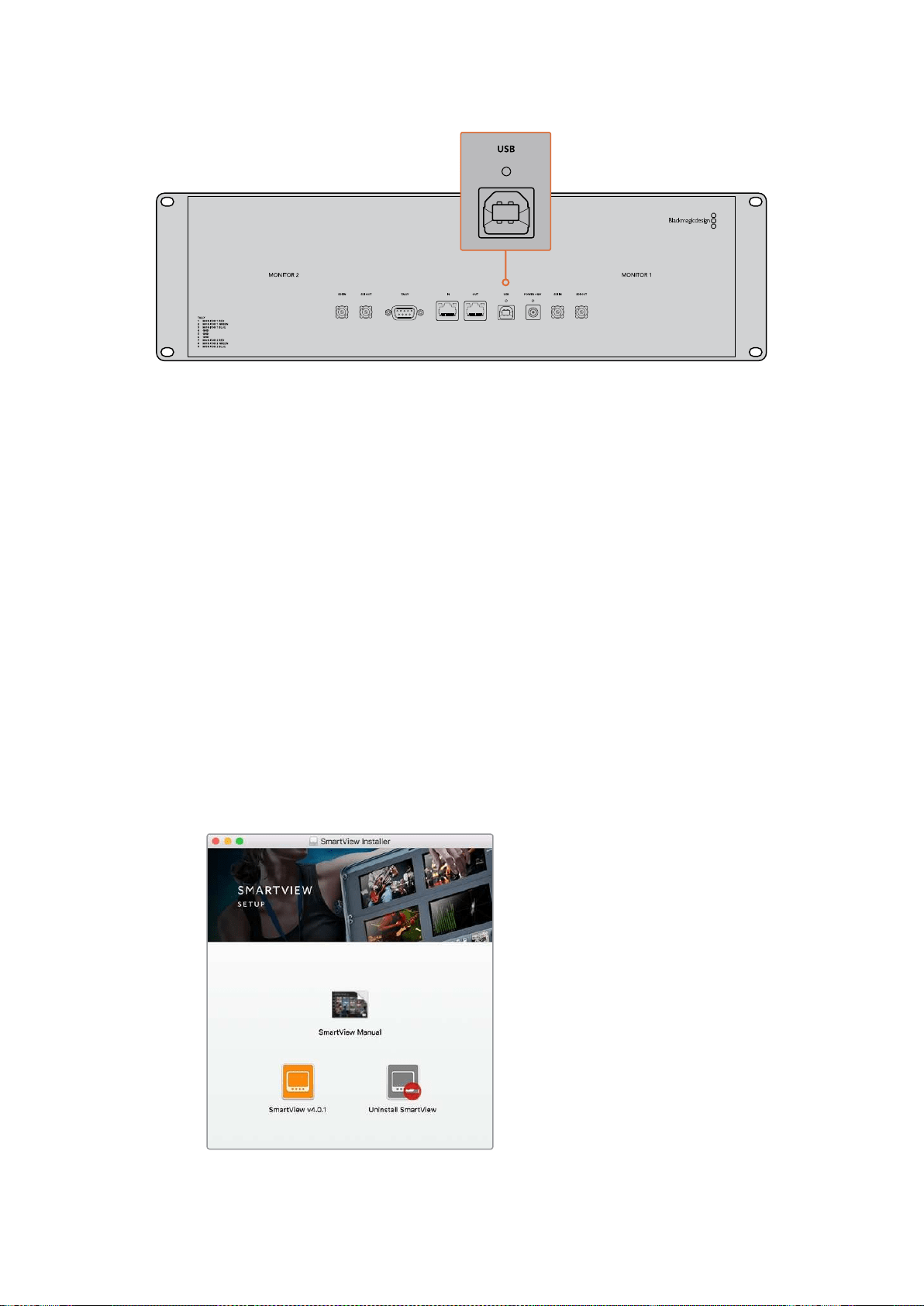
121Erste Schritte
Blackmagic SmartView Setup installieren
Blackmagic SmartView Setup läuft auf den aktuellsten Softwareversionen von Sierra und High Sierra
von macOS sowie auf allen 64-Bit-Versionen von Windows 8.1 und 10, bei denen die aktuellsten
Service Packs installiert wurden. Blackmagic SmartView Setup lässt sich bei Bedarf auf mehreren
Computern im Netzwerk installieren.
Die mit dem SmartView mitgelieferte SD-Karte enthält das Installationsprogramm. Dennoch empfehlen
wir Ihnen einen Besuch auf unsere Website unter www.blackmagicdesign.com/de/support,
um sicherzustellen, dass Sie im Besitz der aktuellsten Version sind.
Installation unter macOS:
Öffnen Sie die mitgelieferte SD-Karte oder laden Sie das Disk-Image herunter und führen Sie auf
dem Installations-Icon von SmartView einen Doppelklick aus. In Ihrem Programme-Ordner wird
daraufhin ein Ordner mit dem Namen „SmartView“ erstellt. Dieser enthält die Blackmagic SmartView
Setup Software, ein Deinstallationsprogramm zum Entfernen älterer Versionen im Falle einer
Aktualisierung und einen Dokumente-Ordner mit diesem Handbuch sowie anderen Informationen
zum SmartView.
Installation unter Windows:
Öffnen Sie auf Ihrem Windows-Computer die mitgelieferte SD-Karte oder die heruntergeladene
ZIP-Datei und führen Sie auf dem Installations-Icon von SmartView einen Doppelklick aus. Folgen
Sie den Bildschirmanweisungen zur Fertigstellung der Installation.
Öffnen Sie zur Installation unter macOS die Datei SmartView.dmg von
der mitgelieferten SD-Karte oder in Ihrem Downloads-Ordner und klicken
Sie anschließend auf das Installations-Icon von SmartView
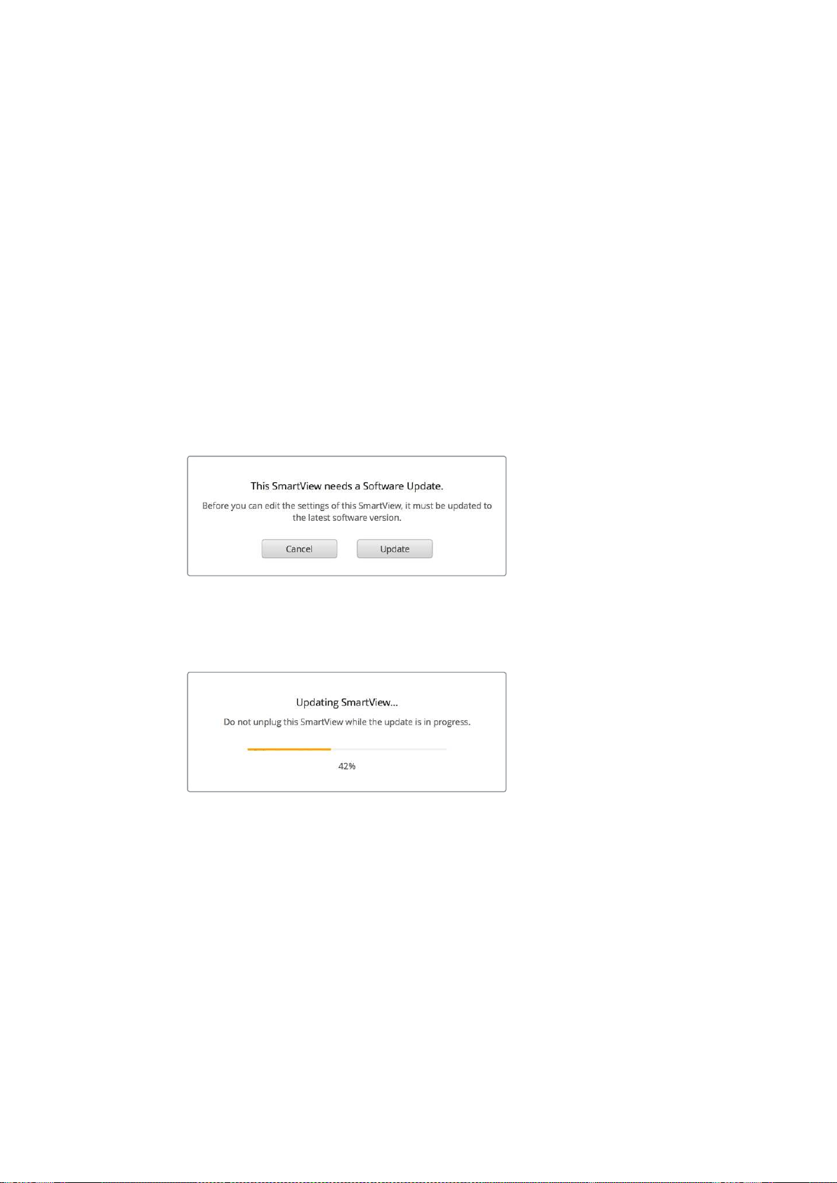
122Blackmagic SmartView SetupimEinsatz
Blackmagic SmartView SetupimEinsatz
Aktualisieren der Software
Ist Blackmagic SmartView Setup installiert und gestartet, klicken Sie auf das Einstellungs-Icon
unterhalb des Monitornamens. Sie werden ggf. aufgefordert, die Produktsoftware Ihres SmartView
oder SmartScope zu aktualisieren. Das geht so:
1 Verbinden Sie Ihren SmartView oder SmartScope per USB-Kabel oder Ethernet mit Ihrem
Computer und starten Sie Blackmagic SmartView Setup.
2 Sollten Sie aufgefordert werden, die Produktsoftware zu aktualisieren, klicken Sie auf
„Update“. Der Aktualisierungsvorgang kann ca. 5Minuten dauern.
3 Die Meldung „This SmartView has been updated“ sollte im Anschluss an die
abgeschlossene Aktualisierung erscheinen.
4 Klicken Sie zum Schließen auf „Close“.
Ist keine Aktualisierung der Produktsoftware notwendig, öffnet sich Blackmagic SmartView Setup
und es erscheint die Einstellungsseite für Ihren Monitor.
Wenn Sie SmartView Setup starten und auf das
Einstellungs-Icon eines angeschlossenen SmartView
oder SmartScope klicken, erscheint diese Meldung,
sollte eine Softwareaktualisierung erforderlich sein
Der Aktualisierungsvorgang dauert ca. 5Minuten
Anpassen der Monitoreinstellungen
Blackmagic SmartView Setup sucht bei jedem Start sofort nach verbundenen SmartView oder
SmartScope Einheiten, die per USB oder Ethernet verbunden sind. Diese werden dann auf der
Homepage von SmartView Setup angezeigt. Sollten Sie mehr als einen Blackmagic Monitor in Ihr
Netzwerk eingebunden haben, selektieren Sie den Monitor, dessen Einstellungen Sie anpassen
möchten, indem Sie auf den Links- oder Rechtspfeil seitlich der Homepage klicken. Ist Ihr
Blackmagic Monitor per USB verbunden, erscheint ein USB-Icon neben dem Monitornamen.
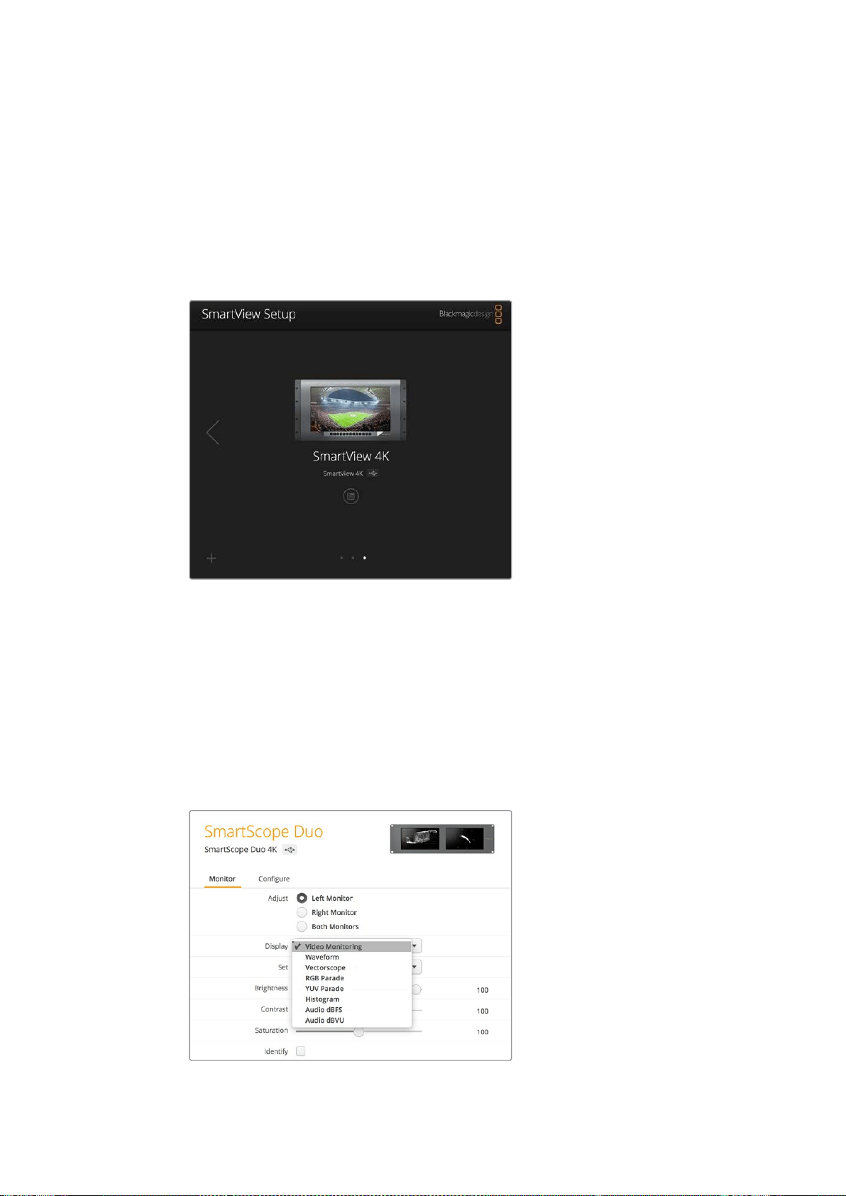
123Blackmagic SmartView SetupimEinsatz
Wählen Sie zum Anpassen der Einstellungen Ihren per Ethernet oder USB verbundenen Monitor
aus und klicken Sie auf das Einstellungs-Icon unter dem Monitornamen. Dadurch öffnet sich die
Einstellungsseite des ausgewählten Monitors. Haben Sie die Einstellungen nach Ihren Bedürfnissen
angepasst, klicken Sie auf „Save“, um Ihre Einstellungen zu speichern und zur SmartView Setup
Homepage zurückzukehren.
Im nächsten Abschnitt erfahren Sie mehr über die für Blackmagic Monitore verfügbaren
Einstellungen und wie Sie diese anwenden. Weitere Informationen zur Konfiguration von
Netzwerkeinstellungen mithilfe von SmartView Setup finden Sie im Kapitel „Anpassen von
Netzwerkeinstellungen“.
Blackmagic SmartView Setup sucht automatisch nach lokal per USB
angeschlossenen oder per Netzwerk eingebundenen SmartView und
SmartScope Einheiten. Vergewissern Sie sich bei der Aktualisierung
der Produktsoftware Ihres Monitors, dass dieser per USB oder Ethernet
verbunden ist. Ein USB-Icon erscheint dann neben dem Monitornamen.
Monitoreinstellungen
Um die Einstellungen und Displays eines jeden Monitors anzupassen, müssen diese per Ethernet
oder USB angeschlossen sein. Wählen Sie den einzustellenden Monitor aus, indem Sie auf der
SmartView Setup Homepage auf den Links- bzw. Rechtspfeil und anschließend auf das Einstellungs-
Icon unter dem Monitornamen klicken. Die Einstellungsseite zeigt jeweils die von Ihrem
ausgewählten Blackmagic Monitor unterstützten Funktionen an.
Beim SmartScope können Sie im Drop-down-Menü „Display“
zwischen den Optionen „Scopes“ und „Video Monitoring“ wählen
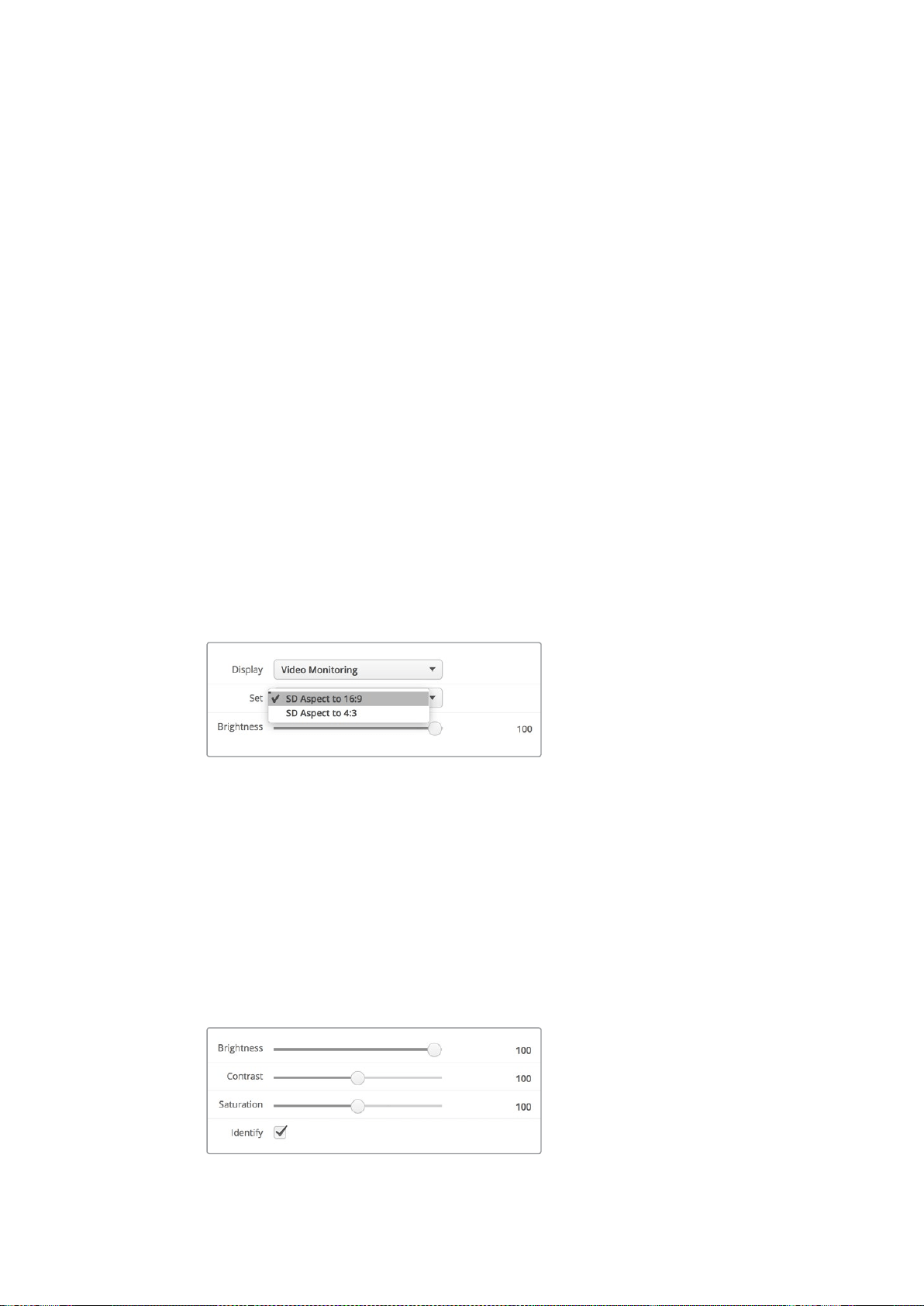
124Blackmagic SmartView SetupimEinsatz
Adjust
Bei einem SmartScope bzw. SmartView Duo legen Sie hiermit fest, welchen Monitor Sie anpassen
können. Wählen Sie für den linken Monitor, „Left Monitor“, für den rechten „Right Monitor“ oder für
beide Monitore „Both Monitors“ aus. Wenn die Option „Both Monitors“ aktiviert ist, werden jegliche
Anpassungen hinsichtlich Helligkeit, Kontrast und Sättigung auf beide Monitore des SmartView
Duo bzw. SmartScope Duo angewandt.
Display
Bei Einsatz eines SmartScope zeigt das Drop-down-Menü „Display“ auswählbare Scopes an.
Wählen Sie die Option „Video Monitoring“, wenn Sie das Videobild angezeigt bekommen wollen.
Set
Wenn Sie beim SmartScope die Display-Option „Video Monitoring“ vorgegeben haben, können Sie
für SD-Video im Drop-down-Menü „Set“ zwischen den Bildseitenverhältnissen „SD Aspect to 4:3“
oder „SD Aspect to 16:9“ wählen. Das Drop-down-Menü „Set“ bietet darüber hinaus zusätzliche
Optionen für das ausgewählte Display an, darunter „Vectorscope“, „Audio dBFS“ und „Audio dBVU“.
Video Monitoring: Wählen Sie diese Option, um das Videobild im 4:3- oder
16:9-Seitenverhältnis anzuzeigen.
Bei anamorphotischem SD-Video im Breitbildformat, wählen Sie das 16:9-Seitenverhältnis.
Bei traditionellem 4:3-Video in Standard Definition, wählen Sie das 4:3-Seitenverhältnis.
Vectorscope: Geben Sie vor, ob Ihre Eingabe auf Farbbalken-Testsignalen von 100% oder
75% basiert.
Audio dBFS: Wählen Sie das Audiokanalpaar, dessen Phasen Sie überprüfen möchten.
Audio dBVU: Wählen Sie das Audiokanalpaar, dessen Phasen Sie überprüfen möchten.
Wählen Sie „SD Aspect to 16:9“ für anamorphotisches Standard-Definition-Video
Brightness, Contrast, Saturation
Passen Sie mit diesen Schiebereglern Helligkeit, Kontrast und Sättigung an.
Identify
Ist das Kontrollkästchen „Identify“ mit einem Häkchen aktiviert, wird das Display des derzeit in
Blackmagic SmartView Setup ausgewählten Monitors weiß umrandet. Bei mehreren
angeschlossenen SmartView und SmartScope Einheiten, lässt sich der ausgewählte Monitor so
leicht visuell identifizieren.
Ist das Kontrollkästchen zusammen mit der Option „Both Monitors“ aktiviert, erscheint die weiße
Umrandung auf den Displays beider SmartView Duo oder SmartScope Duo 4K Monitore.
Ziehen Sie die Schieberegler nach links oder rechts, um die Einstellungen für
Helligkeit, Kontrast und Sättigung anzupassen. Setzen Sie im Kontrollkästchen
„Identify“ ein Häkchen, um den ausgewählten Monitor zu markieren
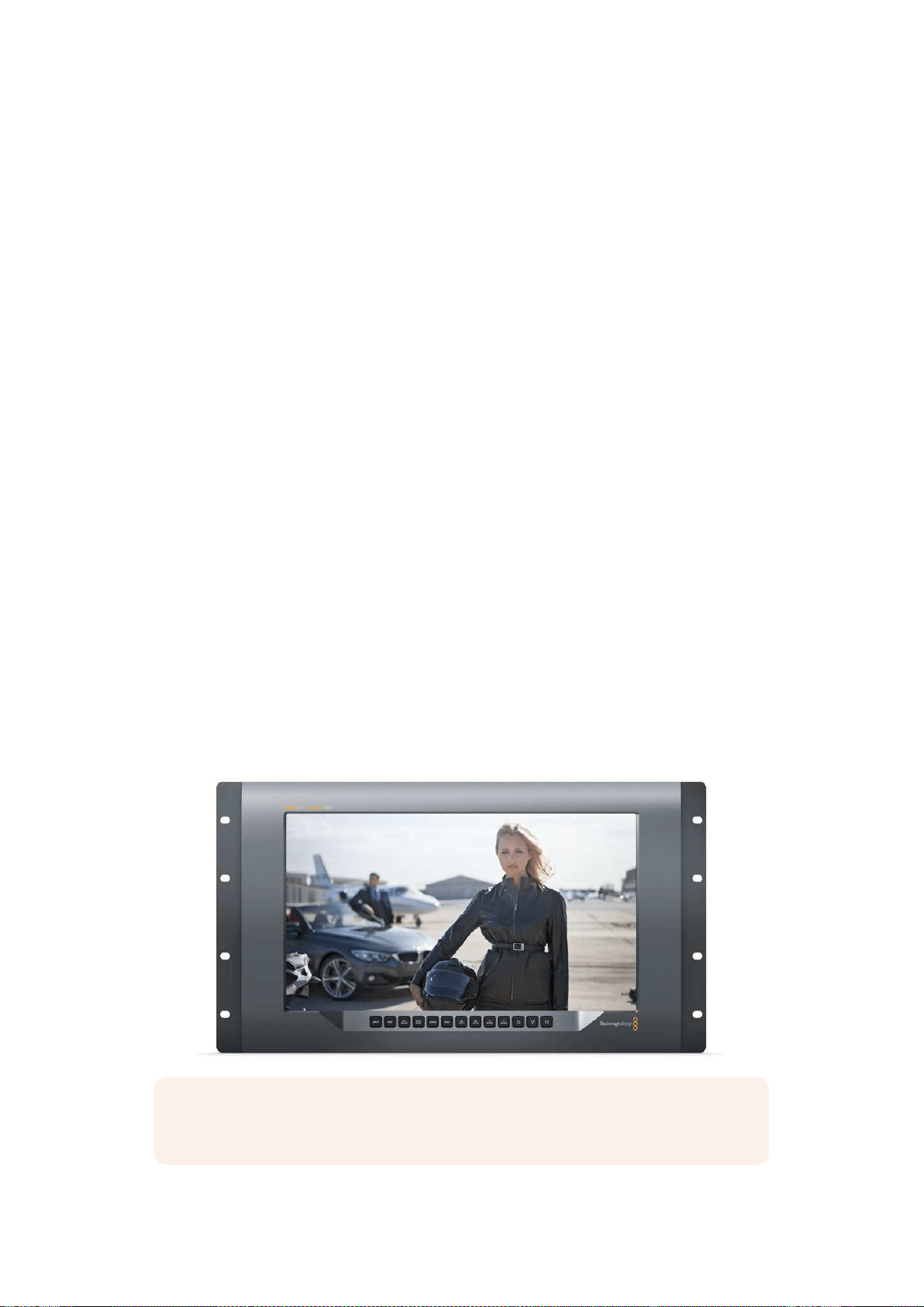
125Der SmartView 4K im Einsatz
Der SmartView 4K im Einsatz
Der Blackmagic SmartView 4K
Der SmartView 4K ist ein 6HE großer Broadcastmonitor mit 12G-SDI zur Darstellung von SD-, HD-
und sogar Ultra-HD-Video in nativem 2160p/60. Mit seinem hellen Display und breiten
Betrachtungswinkel sorgt er für lebhafte, kristallklare Bilder für akkurates Fokus- und
Farbmonitoring. Darüber hinaus unterstützt er praktisch jedes Videoformat.
Der SmartView 4K wurde sowohl fürs Studio als auch fürs Field-Broadcasting konzipiert und ist leicht
zu bedienen. Dank der seitlich angebrachten Anschlüsse und seiner VESA-Konformität findet der
Monitor auch auf beengtem Raum Platz. Alternativ lässt er sich an eine Wand montieren oder an
einer schwenkbaren Halterung befestigen. Der SmartView 4K lässt sich über das integrierte
Bedienfeld steuern. An Standorten, die keinen Zugang zum Frontbedienfeld gewähren, kann er auch
per Ethernet aus der Ferne gesteuert werden.
Zwei Multi-Rate-12G-SDI-Eingänge lassen Sie zwischen zwei SDI-Quellen wählen. Außerdem gibt es
einen SMPTE-konformen SFP-Modul-Käfig zum Anschließen eines SDI-Glasfasermoduls, damit Sie
Ihr Video per Glasfaser verbinden können. Über den 12G-SDI-Ausgang können Sie Ihre
Videosignale an anderes Equipment weiterleiten. Zwei Ethernet-Anschlüsse dienen indes zur
Netzwerkeinbindung, zur Fernsteuerung sowie als Durchschleifausgang bei der Reihenschaltung
mehrerer Monitore. Zu den übrigen Anschlüssen zählen ein Tally-Eingang für Live-Produktionen
und ein USB-Port für Aktualisierungen der Produktsoftware.
Mithilfe der Blackmagic SmartView Setup Software lassen sich sogar branchenübliche 3D-LUTs mit
der Dateierweiterung .cube oder auch in DaVinci Resolve generierte LUTs laden. Wenn Sie Ihren
SmartView 4K direkt an Ihre Kamera anschließen, können Sie Ihre Clips dank der LUT im
gewünschten Look sichten. Mit zwei Schärfestufen für Focus Peaking gehen Sie sicher, dass Ihre
Einstellungen immer perfekt fokussiert sind. Und aufgrund der Unterstützung für AC- sowie DC-
Strom bleibt es Ihnen überlassen, ob Sie den SmartView 4K per Netzstrom oder– wenn Sie am Set
frei beweglich bleiben möchten– per externem Akku betreiben.
Der SmartView 4K ist die perfekte Monitoring-Lösung für Broadcastproduktionen, ob unterwegs
oder im Studio. Er zeigt Video in SD, HD und Ultra HD in nativer 3840x2160 Pixelauflösung an.
HINWEIS Sollten Sie eine externe Stromquelle über den DC-Eingang anschließen,
vergewissern Sie sich, dass der Stromausgang dieser Quelle 24Watt bei 12Volt speist.
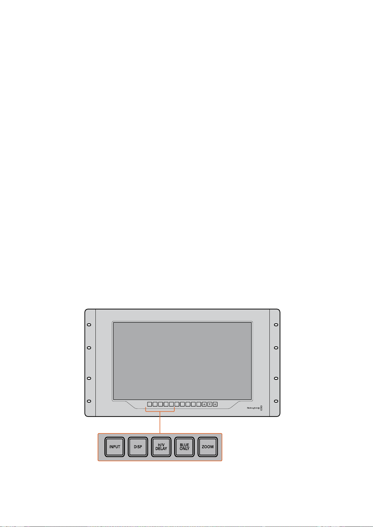
126Der SmartView 4K im Einsatz
Bedientasten
Das Bedienfeld verfügt über eine Reihe Tasten, mit denen Sie Einstellungen an Ihrem SmartView 4K
im Handumdrehen ändern können.
INPUT
Mit dieser Taste durchlaufen Sie alle Videosignale, die über die 12G-SDI-Eingänge bzw. den
optionalen SFP-Glasfaseranschluss an Ihren SmartView 4K gekoppelt sind. Liegt an einem Eingang
kein Videosignal vor, zeigt der SmartView 4K für diesen Eingang schwarzen Bildinhalt an. Wenn Sie
zwischen Eingängen hin und her schalten, werden in der linken oberen Monitorecke kurzzeitig
Informationen zum Eingabeformat angezeigt.
DISP
Mit der DISP-Taste passen Sie die Helligkeit des LCDs Ihres SmartView 4K an. Stellen Sie die
Helligkeit anhand der Aufwärts- und Abwärtspfeile nach Bedarf ein. Drücken Sie erneut auf DISP,
um die Einstellung zu schließen.
H/V DELAY
Anhand der Taste H/V DELAY lässt sich das Vorhandensein eingebetteter Zusatzdaten in Ihrem
SDI-Videosignal ruckzuck überprüfen. Beispiel: Drücken Sie die H/V-DELAY-Taste einmal, um
horizontale Zusatzdaten anzuzeigen. Drücken Sie die Taste erneut, um vertikale Zusatzdaten
anzuzeigen. Dabei handelt es sich oft um häufig verwendete Daten wie bspw. geschlossene Untertitel.
BLUE ONLY
Ist in einem digitalen Videosignal Bildrauschen vorhanden, tritt es am stärksten im blauen Kanal auf.
Dieses Bildrauschen im blauen Kanal lässt sich anhand der BLUE-ONLY-Taste überprüfen. Daraufhin
wird lediglich der blaue Kanal in Form eines Schwarzweißbilds angezeigt. Das Schwarzweißbild
können Sie auch als Hilfe beim Kontrollieren der Kamerafokussierung verwenden.
ZOOM
Gestochen scharfe Bilder durch exakten Kamerafokus erzielen Sie mit der ZOOM-Taste. Drücken Sie
die Taste einmal, um in das Bild hineinzuzoomen. Nun können Sie ganz klar sehen, ob ein Objekt
scharf fokussiert ist. Drücken Sie die ZOOM-Taste erneut, um zur normalen Ansicht zurückzukehren.
INPUT DISP
H/V
DELAY
3D
LUT 1
BLUE
ONLY
ZOOM PEAK
3D
LUT 2
H
MARK
V
MARK
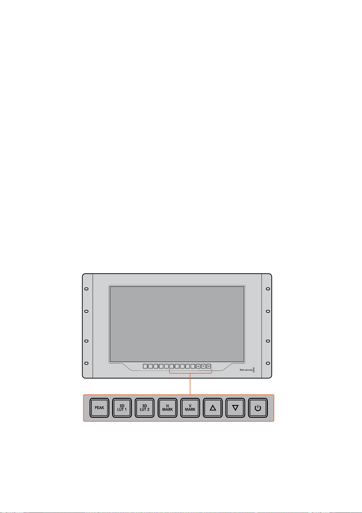
127Der SmartView 4K im Einsatz
PEAK
Der Kamerafokus lässt sich ganz leicht überprüfen, indem Sie die PEAK-Taste drücken und damit
Focus Peaking aktivieren. Dadurch wird eine grüne Markierung um die schärfsten Bereiche Ihres
Bilds herum eingeblendet. Es stehen zwei Schärfestufen für Peaking zur Verfügung. Wechseln Sie
durch mehrmaliges Drücken zwischen den unterschiedlichen Einstellungen hin und her. Sobald die
grünen Markierungen am stärksten sind, wissen Sie, dass Ihre Kamera fokussiert hat.
3D LUT 1 und 3D LUT 2
Mithilfe der LUT-Tasten können Sie Ihr Videobild mit LUTs anzeigen lassen. Das funktioniert sowohl
mit LUTs, die Sie selbst in Blackmagic DaVinci Resolve erstellt haben, als auch mit branchenüblichen
.cube-LUTs. Drücken Sie eine der LUT-Tasten, um die jeweilige LUT zu aktivieren. Drücken Sie die
Taste erneut, um die LUT zu deaktivieren. Weitere Informationen zur Verwendung von 3D-LUTs auf
dem SmartView 4K finden Sie im Abschnitt „3D-LUTs mit Blackmagic SmartView Setup laden“.
H MARK und V MARK
Mit den Tasten H MARK und V MARK können Sie Bildrandmarkierungen anzeigen und bearbeiten.
Bildrandmarkierungen unterstützen Sie bei der Komposition von Einstellungen und helfen dabei,
Informationen und Grafiken innerhalb des Schutzbereiches auf dem Bildschirm anzuzeigen. Je nach
Größe des Fernsehers wird mal mehr und mal weniger von den Kantenbereichen des Videosignals
wiedergegeben. Daher ist es praktisch, sich einen Schutzbereich anzeigen zu lassen. Beim
Schutzbereich handelt es sich um den Bereich des Bildschirms, der immer sichtbar ist, unabhängig
vom Modell des Fernsehers bzw. Monitors.
Um horizontale und vertikale Bildrandmarkierungen anzuzeigen, drücken Sie die entsprechende
Taste, also H MARK oder V MARK. Wenn Sie die Markierung anpassen wollen, drücken Sie die
jeweilige Taste erneut. Dadurch wird die entsprechende Markierung hervorgehoben. Mithilfe der
Pfeiltasten lässt sich nun die Position der Markierungen anpassen. Ein erneutes Drücken der
jeweiligen Taste bestätigt die neue Position. Mit einem weiteren Druck auf die Taste wird die
Markierung deaktiviert.
Pfeiltasten
Passen Sie Einstellungen wie bspw. die Display-Helligkeit oder Bildrandmarkierungen mithilfe der
Auf- und Abwärtspfeiltasten an.
INPUT DISP
H/V
DELAY
3D
LUT 1
BLUE
ONLY
ZOOM PEAK
3D
LUT 2
H
MARK
V
MARK
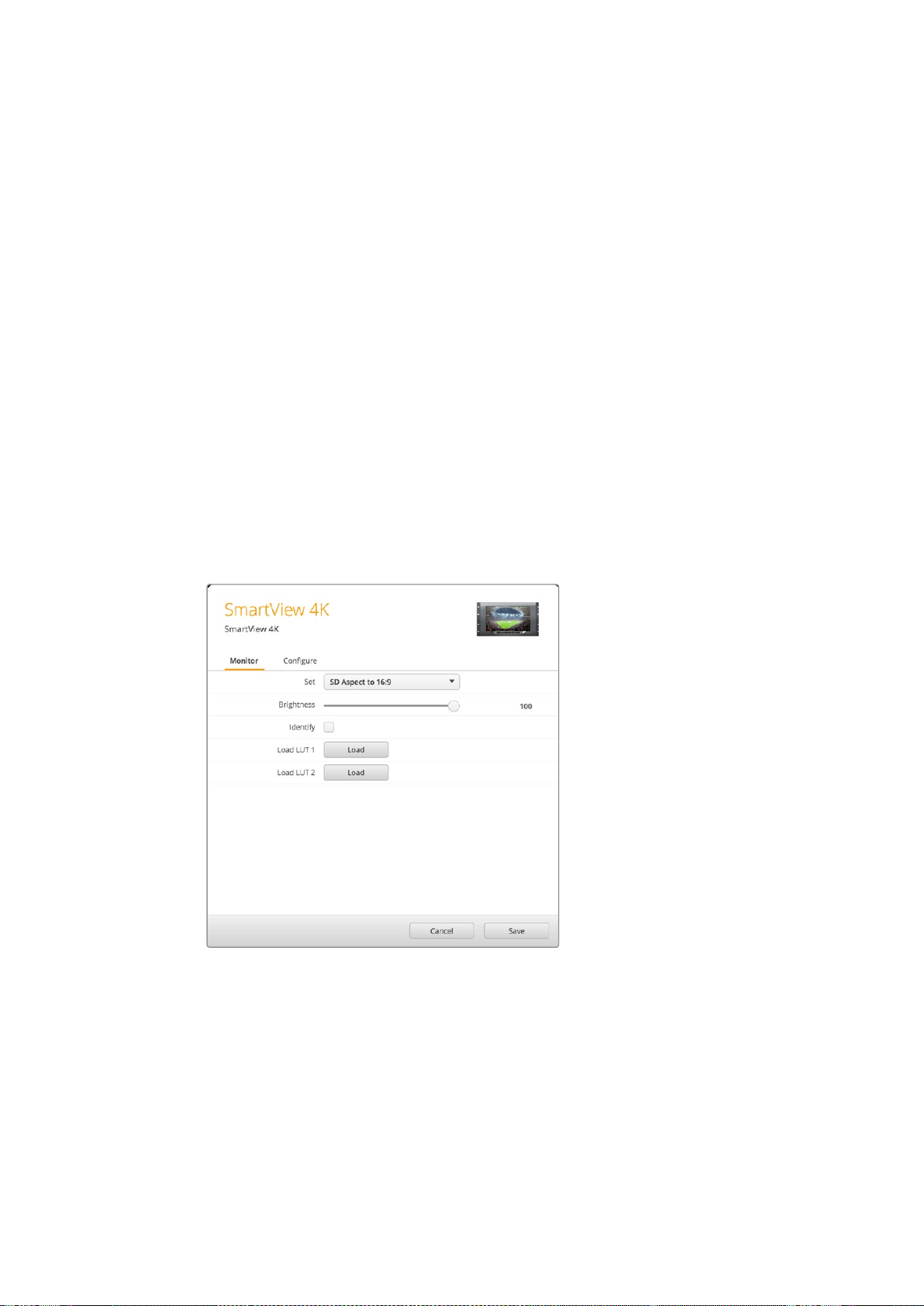
128Der SmartView 4K im Einsatz
Ein-/Austaste
Drücken Sie die Ein- und Ausschalttaste einmal, um Ihren SmartView 4K einzuschalten. Drücken Sie
sie erneut, um ihn auszuschalten.
3D-LUTs mit Blackmagic SmartView Setup laden
Mit dem SmartView 4K können Sie Ihr Video mit angewandten 3D-LUTs überprüfen. Somit haben Sie
die Möglichkeit, Ihren SmartView 4K anhand von professionellen LUTs zu kalibrieren oder Ihr Video
im angestrebten Look zu sichten. Darüber hinaus können Sie mit unterschiedlichen Looks
herumexperimentieren. LUTs werden über die Blackmagic SmartView Setup Software auf den
SmartView 4K geladen. Da der SmartView 4K branchenübliche LUT-Dateien mit der Erweiterung
.cube unterstützt, können Sie sogar eigens in Blackmagic DaVinci Resolve erstellte LUTs verwenden.
Details zur Erstellung von LUT-Dateien finden Sie im englischsprachigen DaVinci Resolve Handbuch.
So belegen Sie die Taste 3D LUT 1 mit einer 3D-LUT:
1 Starten Sie Blackmagic SmartView Setup.
2 Klicken Sie auf den „Load“-Button neben „Load LUT 1“. Es öffnet sich ein Fenster, das nach
dem Pfad der zu ladenden LUT-Datei fragt. Wählen Sie die gewünschte .cube-LUT-Datei
aus und öffnen Sie sie mit „Open“.
3 Um die soeben geladene LUT zu sichten, drücken Sie die Taste 3D LUT 1 auf dem
SmartView 4K Bedienfeld. Drücken Sie die Taste erneut, um die LUT zu deaktivieren.
Folgen Sie denselben Schritten, um die Taste 3D LUT 2 mit einer LUT zu belegen.
Laden Sie 3D-LUTs mithilfe von Blackmagic
SmartView Setup auf Ihren SmartView 4K

129Der SmartScope Duo 4K im Einsatz
Der SmartScope Duo 4K im Einsatz
Was ist der Blackmagic SmartScope?
Früher waren in der TV- und Postproduktion eingesetzte Messgerätefür Bild und Ton von
Broadcastqualität unglaublich kostspielige Maßlösungen. Trotzdem konnte jeweils nur eine einzige
Messanzeige auf einem winzigen Bildschirm angezeigt werden. Manche dieser Messgeräte sahen
geradezu unattraktiv aus und machten vor Kunden keinen guten Eindruck.
Mit dem SmartScope Duo 4K bekommen Sie zusätzlich zur Bildkontrolle die Funktionen eines
Waveform-Monitors. Behalten Sie so alle Aspekte Ihres Videosignals auf beiden Bildschirmen
echtzeitbasiert im Auge. Jegliche Änderungen am Eingabesignal in Blackmagic SmartView Setup
werden sofort auf dem SmartScope Duo 4K sichtbar. Jedes Eingabesignal kann über den
Durchschleifausgang an einen beliebigen der beiden Monitore gesendet werden. So können Sie
z.B. auf dem rechten Monitor ein Scope für das Videosignal des linken Monitors anzeigen.
Die Auswahl der jeweils auf dem SmartScope Duo 4K angezeigten Messanzeige wird in Blackmagic
SmartView Setup ausgewählt. Wählen Sie Ihr Scope aus dem Drop-down-Menü „Display“ aus.
Auf den folgenden Seiten erfahren Sie, wie die einzelnen Messanzeigen anzuwenden sind, damit
Sie einen Einblick bekommen, inwieweit die Anzeigen Ihnen helfen können.
Mithilfe von Blackmagic SmartView Setup lassen sich jedem
der beiden Monitore unterschiedliche Scopes zuweisen
Die Video-Monitoring-Anzeige
Die Video-Monitoring-Anzeige stellt das vom SmartScope empfangene Videobild dar und gibt Ihnen
beim Monitoring eine praktische visuelle Referenz.
Liegt Ihr Eingabesignal in SD vor, können Sie im Drop-down-Menü „Set“ zwischen den Ansichtsmodi
„SD Aspect to 4:3“ oder „SD Aspect to 16:9“ wählen. An der LCD-Helligkeit, den Kontrast- oder
Sättigungseinstellungen vorgenommene Änderungen werden in der Ansicht sofort sichtbar. Bitte
beachten Sie, dass sich diese Änderungen lediglich auf das Monitorbild auswirken, nicht auf das
Videosignal. Aus diesem Grund können Änderungen hinsichtlich Sättigung oder Helligkeit in den
Scopes nicht nachvollzogen werden.
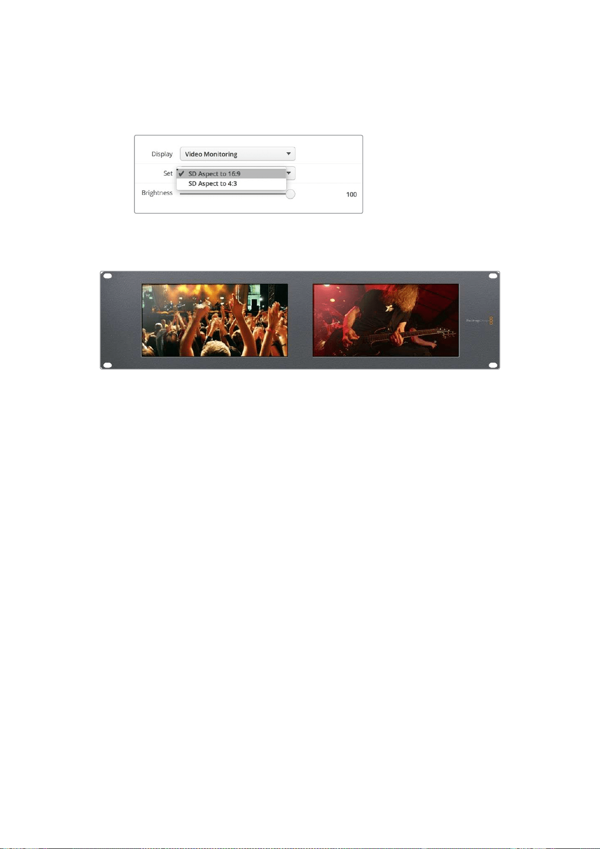
130Der SmartScope Duo 4K im Einsatz
Oft ist es hilfreich, einen Bildschirm als Video-Monitoring-Anzeige und den anderen als Scope zu
nutzen. Verbinden Sie hierzu mit einem kurzen Kabel den SDI-Durchschleifausgang von Monitor 1
mit dem SDI-Eingang von Monitor 2.
Lassen Sie sich SD-Video im 4:3-Pillarbox- oder 16:9-Breitbildformat anzeigen, indem
Sie die gewünschte Option im „Set“-Menü in Blackmagic SmartView Setup wählen.
Wählen Sie für anamorphotisches Video in Standard Definition „SD Aspect to 16:9“
Die Video-Monitoring-Anzeige zeigt das Videosignal so an,
wie es auf einem Fernseher oder Monitor erscheinen würde
Waveform-Anzeige
Die Waveform-Anzeige liefert eine digital kodierte Wellenform, die denen herkömmlicher Waveform-
Monitore für Luminanz ähnelt. Sie wird genutzt, um die Luma- bzw. Helligkeitspegel Ihres
Videosignals zu kontrollieren und anzupassen.
Herkömmliche Luminanz-Waveform-Monitore unterstützen nur analoges FBAS-Video in Standard
Definition. Der Waveform-Monitor des SmartScope Duo 4K funktioniert hingegen auch in Ultra HD,
HD und in SD. So sind Lumapegel auch beim Monitoring digitaler Videoformate in High Definition
durchgängig und mühelos anpassbar.
Wählen Sie in Blackmagic SmartView Setup im Drop-down-Menü „Display“ die Option „Waveform“
aus. Vergewissern Sie sich, dass die Schwarztöne im Kurvenverlauf nicht unter 0% und die
Weißtöne nicht über 100% liegen. Andernfalls geraten Ihre Lumawerte in den unzulässigen Bereich.
Der Waveform-Monitor zeigt eine grafische Repräsentation des Videobilds an, die die Lumawerte
entsprechend der Position innerhalb eines Bilds darstellt. Ist bspw. ein Teil des Himmels
überbelichtet, sehen Sie dies in der Waveform-Anzeige in derselben horizontalen Position, in der
sich die Überbelichtung auch im Einzelbild befindet.
Der Kurvenverlauf ändert sich je nach Bildinhalt. Wenn Sie kontrastreiche Videobilder kontrollieren,
kann es sein, dass in den mittleren Graubereichen keine Werte vorhanden sind. Das Bild unten zeigt
den Kurvenverlauf eines gleichmäßig belichteten Bilds an, mit einem dunklen Fleck auf der linken
Seite und helleren Werten, die sich von der Mitte des Bilds zur rechten Seite hinziehen.

131Der SmartScope Duo 4K im Einsatz
Ein Luminanzwerte darstellender Kurvenverlauf
Wählen Sie in Blackmagic SmartView Setup in den „Display“-Einstellungen die
Option „Waveform“ aus, um die Luminanzwerte Ihres Videosignals anzuzeigen
Vektorskop-Anzeige
Die Vektorskop-Anzeige veranschaulicht die in einem Videosignal enthaltenen Farben anhand eines
Vektors. Wählen Sie je nach Norm der in Ihrer Sendeanstalt eingesetzten Farbbalken-Testsignale in
Blackmagic SmartView Setup aus dem Drop-down-Menü „Set“ einfach die Option „100%“
oder „75%“.
Viele Benutzer glauben, dass sich mit einer Vektorskop-Anzeige unzulässige Pegel kontrollieren
lassen. Das ist jedoch nicht richtig. Nicht konforme Farben prüft man mit der RGB-Parade-Anzeige.
Für die Prüfung unzulässiger Pegel verbietet sich der Einsatz eines Vektorskops, da neben
Chromawerten außerdem Helligkeitswerte nötig sind. Beispielsweise können Farbwerte in der Nähe
des Weiß- oder Schwarzpunkts im Video nicht so stark gesättigt sein, wie die viel stärkeren Farben
in den mittleren Farbbereichen. Da die Vektorskop-Anzeige ausschließlich Farben, aber keine
Helligkeitswerte anzeigt, ist sie für die ausschließliche Prüfung unzulässiger Farben nicht geeignet.
Am besten eignet sich die Vektorskop-Anzeige, um die Farbpegel älterer, analoger Videobänder zu
prüfen, deren Chromawerte anzupassen sind. Spielen Sie einfach das Farbbalken-Segment des
Videobands ab und passen Sie dann die Chroma- und Farbtoneinstellungen an, sodass die Farben
des Videos in die rechteckigen Boxen der Markierung fallen.
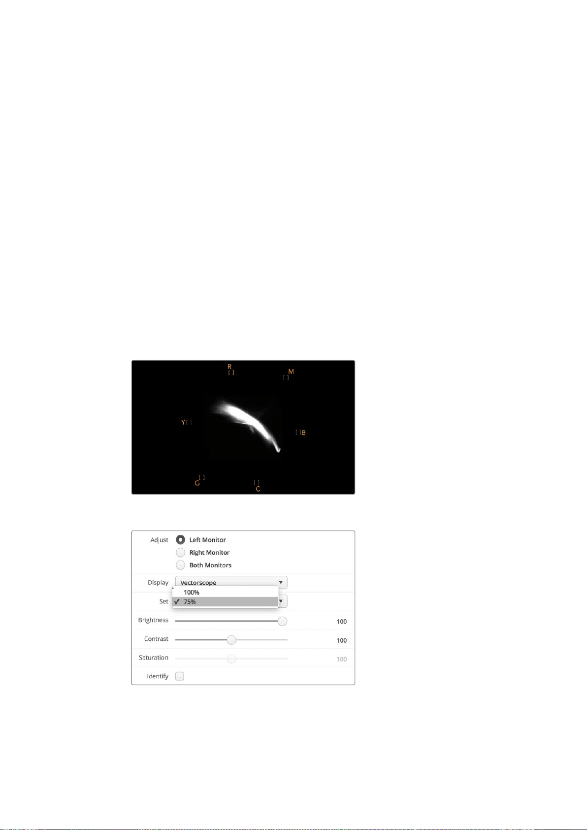
132Der SmartScope Duo 4K im Einsatz
Die Vektorskop-Anzeige bietet sich auch für die Farbkorrektur an, weil leicht erkennbar ist, ob der
Weißabgleich Ihres Videos stimmt oder ob es einen Farbstich hat. Sollte Ihr Video einen Farbstich
haben, erscheint die Vektorskop-Darstellung nicht mittig und Sie sehen ggf. zwei Punkte in der
Mitte. Normalerweise entsteht durch die Austastung im Videosignal ein Punkt in der Mitte des
Vektorskops. Dem ist so, weil die Austastlücke aus schwarzem Bildinhalt besteht. Austastlücken
geben einen nützlichen Anhaltspunkt und lassen schwarze Videobereiche ohne jegliche
Farbinformationen erkennen.
Weist Ihr Video einen Farbstich auf, sollte zu beobachten sein, dass sich die Schattenwerte von
den Farben und aus der Mitte entfernen. Der Verschiebungswinkel stellt den Grad des Farbstichs
in Ihrem Video dar. Die Verschiebung ist in den weißen und den schwarzen Details Ihres Videos
sichtbar. Aus diesem Grund ist die Vektorskop-Anzeige ein nützliches Werkzeug, um Farbstiche
zu entfernen und den korrekten Weißabgleich wiederherzustellen.
Mithilfe der Vektorskop-Anzeige können Sie die Farben in Ihrem Video bis an die Grenzen
ausreizen, ohne dabei den Schwarz- und Weißtönen versehentlich ungewollte Farbstiche zu
verleihen. Der Weißabgleich lässt sich zwar ebenso mit der RGB-Parade wie mit dem Vektorskop
prüfen, etwaige Probleme sind in der Vektorskop-Anzeige jedoch oftmals leichter erkennbar.
Für Farbkorrekturen an Bildmaterial mit Hauttönen empfiehlt es sich, die Sättigung der warmen
Farben auf dem Vektorskop entlang des feinen, diagonalen Strichs bei ca. 10Uhr zu konzentrieren.
Da die sogenannte Hauttonlinie sich nach der typischen Farbe von Blut an der Hautoberfläche
richtet, gilt sie für alle Hautpigmentierungen. Deshalb gibt es keine bessere Methode, um die
Hautfarbe Ihrer Darsteller natürlich erscheinen zu lassen.
Vektorskop, das die Hauttonlinie nahe der 10-Uhr-Position anzeigt
Stellen Sie Ihr Vektorskop auf ein Farbbalken-Testsignal
von 100 % oder 75% ein
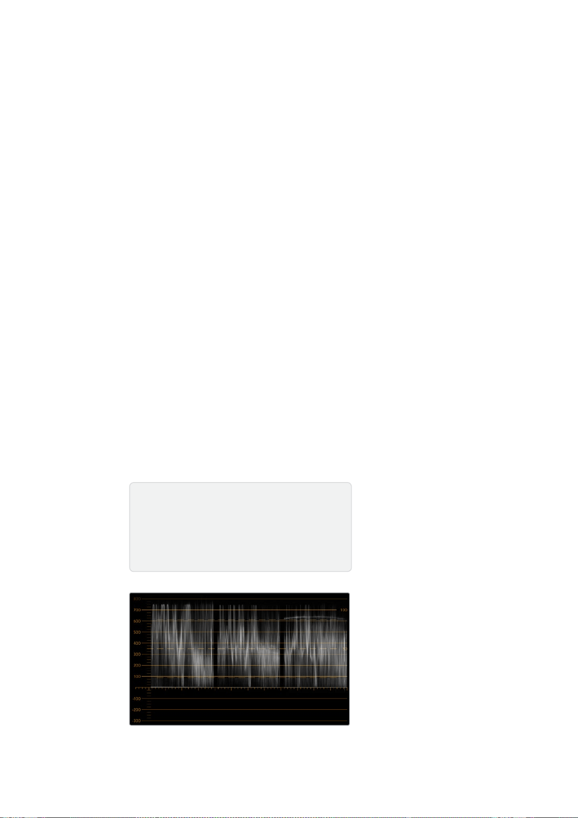
133Der SmartScope Duo 4K im Einsatz
Parade-Anzeige
RGB- und YUV-Parade-Anzeigen eignen sich perfekt für die Farbkorrektur, zur Kontrolle
unzulässiger Farben und zur Überprüfung von Pegeln.
Wählen Sie bei der Farbkorrektur in Blackmagic SmartView Setup im Drop-down-Menü „Display“ die
Option „RGB Parade“ aus. Die RGB-Parade stellt die gesamte Höhe des roten, grünen und blauen
Farbkanals dar. Die Kontrolle der Pegel eines jeden Farbkanals vereinfacht die Farbkorrektur und
macht es leicht, die Farbbalance des Videosignals in den dunklen, mittleren und hellen Bereichen
auszugleichen. Die RGB-Parade-Anzeige ermöglicht es Ihnen, gemeinsame Komponenten des
roten, grünen und blauen Farbkanals zu identifizieren. Das erleichtert den Farbabgleich und das
Entfernen unerwünschter Farbstiche.
Bei der Farbkorrektur ist es wichtig sicherzugehen, dass die Videopegel zwar voll ausschlagen,
jedoch nicht abgeschnitten werden. Achten Sie beim Anheben des Videopegels darauf, dass er
die obere RGB-Grenze nicht überschreitet, da dies zu nicht konformen Pegeln führt. Manche Geräte
lassen Sie keine unzulässigen 100%-RGB-Pegel generieren, andere jedoch schon. Auf dem
SmartScope Duo 4K können Sie auftretende unzulässige Videopegel sofort sehen.
Unzulässige Videopegel können ebenso in den Schwarz- wie auch in den Weißwerten vorkommen.
In einigen Farbkorrektursystemen können die Schwarzwerte unter den Schwarzpunkt von 0%
gesenkt werden. Wenn Sie ungültige Schwarzwerte feststellen, heben Sie lediglich Lift oder Gain
an. Prüfen Sie dabei jedoch die 100%-Marke des Gitternetzes und vergewissern Sie sich, dass das
gesamte Videosignal nicht übermäßig geliftet wurde und nun ungültige Farben in den hellen
Bereichen auftreten.
Um die YUV-Pegel zu überprüfen, wählen Sie im Drop-down-Menü „Display“ die Option „YUV
Parade“ aus. Diese Ansicht ist hilfreich, weil die Lumawerte für die Helligkeit von den Chromawerten
für Farben getrennt sind. Dies ist das gängige Format von Videosignalen bei Fernsehübertragungen.
Der linke Kurvenverlauf bezieht sich auf die Lumainformationen, der zweite und dritte Kurvenverlauf
auf die Chromainformationen. Die YUV-Parade eignet sich für die Kalibrierung der Chromawerte
eines Videosignals gemäß eines Farbbalken-Testmusters, damit Farben akkurat repräsentiert und
die übertragenen Signale von Fernsehern angezeigt werden können.
Die Farbkorrektur ist ein kontinuierlicher Anpassungsprozess, um atemberaubende Bilder zu
schaffen und unzulässige Pegel zu vermeiden.
RGB-Parade-Ansicht
Terminologie zur Farbkorrektur
Blacks– Schwarzwerte im Videosignal
Mids– Grauwerte im Videosignal
Whites– Weißwerte im Videosignal

134Der SmartScope Duo 4K im Einsatz
YUV-Parade-Ansicht
Wählen Sie in Blackmagic SmartView Setup im Drop-down-
Menü „Display“ die Option „RGB Parade“ oder „YUV Parade“
Histogramm-Anzeige
Grafikdesigner und Kameraleute sind mit der Histogramm-Anzeige besonders vertraut.
DieHistogramm-Anzeige stellt die Verteilung der weißen und schwarzen Bildinformationen dar und
lässt Sie kontrollieren, wie nahe diese Details an die Überpegel in den hellen und dunklen Bereichen
heranreichen, die abgeschnitten werden. Die Histogramm-Anzeige stellt auch dar, wie sich in den
mittelhellen Bildpartien Ihres Videos, dem sogenannten Gamma-Bereich, vorgenommene
Änderungen auswirken.
Schwarzwerte werden auf der linken Seite der Anzeige dargestellt und Weißwerte auf der rechten
Seite. Normalerweise sollten alle Videosignale im Bereich der Intervalle von 0–100% der
Histogramm-Anzeige liegen. Videopegel unter 0% oder über 100% werden abgeschnitten.
Während eines Drehs kann es zu übermäßigem Abschneiden von Videoüberpegeln, dem
sogenannten Clipping, kommen. Für spätere Farbkorrekturen in kontrollierter Umgebung müssen
die Details in den schwarzen und weißen Partien jedoch erhalten werden. Halten Sie Ihre
Videopegel beim Filmen über der schwarzen und unter der weißen Clipping-Grenze. So haben
Sie später ausreichend Spielraum bei der Farbanpassung, ohne dass die weißen und schwarzen
Bereiche dabei zu kontrast- oder detailarm wirken.
Vielleicht beschließen Sie bei der Farbkorrektur, Ihr Video in die Überpegel ausschlagen zu lassen.
In diesem Fall zeigt Ihnen das Histogramm den Clipping-Effekt im Video an und wie viel
abgeschnitten wird. Einen ähnlichen Look mit geringeren Videoüberpegeln bei gleichzeitiger
Beibehaltung von mehr Details können Sie sogar mit einer Gamma-Justage erzielen.
Zur Kontrolle unzulässiger Farbpegel ist ein Histogramm ungeeignet, es zeigt Ihnen aber
unzulässige Schwarz- und Weißtöne an. Da das Histogramm keine Farben darstellt, kann die
Histogramm-Anzeige den Anschein erwecken, als befänden sich die Pegel im gültigen Bereich,
selbst wenn Ihr Video unzulässige Farben enthält. Vorzugsweise benutzt man auch hier die
RGB-Parade, um unzulässige Pegel festzustellen, da sie sowohl die Farb- als auch die
Helligkeitselemente des Videosignals anzeigt.

135Der SmartScope Duo 4K im Einsatz
Die Histogramm-Anzeige stellt die Verteilung
der Weiß- und Schwarzwerte dar
Wählen Sie in Blackmagic SmartView Setup im Drop-down-
Menü „Display“ die Option „Histogram“ aus
Audiopegelmeter-Anzeige
Die Audiopegelmeter-Anzeige stellt die Audiopegel des eingebetteten Audios im SDI-Videosignal
dar. Bis zu 16 Kanäle eingebettetes Audio werden aus dem Videosignal isoliert und im dBVU- oder
dBFS-Format angezeigt.
Das bei älteren Geräten sehr gebräuchliche, benutzerfreundliche VU-Meter zeigt durchschnittliche
Signalpegel an. Das VU ist gemäß der SMPTE-Empfehlung mit einem auf -20dBFS eingestellten
1kHz-Tontestsignal kalibriert.
Die bei modernen tontechnischen Digitalgeräten gebräuchliche Einheit dBFS (vollständige
Dezibelskala) bezeichnet die Angabe des absoluten Tonpegels eines digitalen Audiosignals.
Das rechte Audio-Scope kann zwei Audiokanäle überwachen. Diese können aus dem Drop-down-
Menü „Set“ ausgewählt werden, z.B. „Ch 1 & 2“, „Ch 3 & 4“ usw. Das Audio-Scope stellt Audio in
einer X-Y-Ansicht dar. So ist sichtbar, ob es Probleme mit der Audiobalance oder falsche
Phasenlagen gibt und ob eine Audiospur in Mono oder Stereo vorliegt. Mono sollte in einer
vertikalen phasenkorrekten Linie erscheinen. Wird eine horizontale Linie angezeigt, so ist Ihr Audio
phasenverkehrt und könnte beim Empfang nachgeschalteter Geräte ausgelöscht werden (d.h.
Verlust von Audio). In großen Sendeanstalten, wo das Risiko falsch angeschlossener Kabel besteht,
zählen Audiophasenfehler zu den häufigsten Pannen.

136Anschließen an ein Netzwerk
Bei der Überwachung von Stereosignalen fächert sich die Linie des rechten Audio-Scopes aus, was
den Unterschied zwischen den linken und rechten Audiokanälen verbildlicht. Je mehr Stereoton in
einer Audiospur enthalten ist, desto kreisförmiger erscheint die Anzeige. Enthält das Audio minimale
Stereoinhalte, konzentriert sich die Anzeige stärker um die vertikale Achse.
Dialogton erscheint eher als vertikale Linie, wohingegen Musik mit viel Stereoinhalt das Scope
aufgeblasen wirken lässt. Dem ist so, weil Monoaudio L+R ist und auf der vertikalen Achse angezeigt
wird. Stereoinhalte sind hingegen L-R und werden auf der horizontalen Achse angezeigt, um den
Stereounterschied wiederzugeben.
Die Audiopegelmeter-Anzeige zeigt
Spitzenpegel und Audiobalance an
Wählen Sie im Drop-down-Menü „Set“
das zu kontrollierende Audiokanalpaar aus
Anschließen an ein Netzwerk
Wenn Sie einen SmartView oder SmartScope Monitor in ein Netzwerk einbinden, können Sie
Monitoreinstellungen für mehrere Einheiten aus der Ferne ändern.
SmartView und SmartScope Monitore zeigen Video ohne vorherige Konfiguration an.
Netzwerkeinstellungen müssen hingegen vor dem Einsatz vorgegeben werden. Die
Netzwerkkonfiguration ist ausschließlich über eine direkte USB-Verbindung zum Computer möglich.
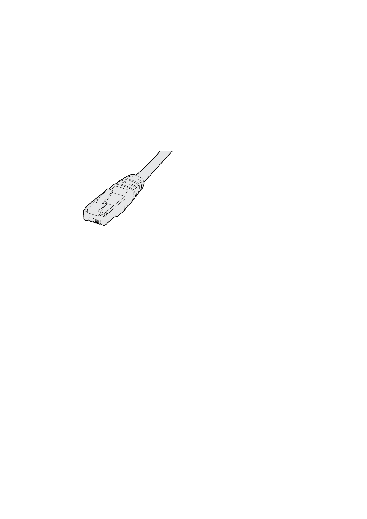
137Anschließen an ein Netzwerk
Direkte Ethernet-Verbindung
Über eine direkte Ethernet-Verbindung zu Ihrem Computer können Sie die Monitorkonfiguration aus
der Ferne vornehmen. Hierfür ist kein Netzwerk-Switch erforderlich. Das ist praktisch, wenn die
Installation und der Aufbau schnell gehen müssen. Zusätzliche Einheiten können über den aktiven
Ethernet-Durchschleifausgang einer jeden Einheit in Reihe geschaltet werden. Dabei muss jede
Einheit selbstständig mit Strom versorgt werden.
Wenn Sie mehrere Einheiten in Reihe schalten möchten, ohne IP-Adressen Ihres vorhandenen
Studionetzwerks zu verwenden, oder wenn kein Netzwerk verfügbar ist, koppeln Sie die Einheiten
einfach direkt an den Ethernet-Port Ihres Computers. Die Reihenschaltung von SmartView und
SmartScope Einheiten per Ethernet geht blitzschnell, weil keine Kabel zum Netzwerk-Switch verlegt
werden müssen.
Ethernet-Stecker
Ethernet-Netzwerk-Switch
Um mehrere Einheiten in Ihr Studionetzwerk einzubinden, brauchen Sie lediglich einen SmartView
oder SmartScope mit dem Netzwerk-Switch zu verbinden. Die übrigen Einheiten lassen sich über
den aktiven Ethernet-Durchschleifausgang eines jeden Geräts in Reihe schalten. Es wird also nur ein
einziger Port an Ihrem Netzwerk-Switch belegt. Das erspart Ihnen das Verlegen unzähliger Kabel
zum Netzwerk-Switch. Bei einer Reihenschaltung muss jede Einheit selbstständig mit Strom
versorgt werden.
Durch die Verbindung zu einem Netzwerk-Switch lassen sich die Einstellungen einer Einheit von
jedem beliebigen Computer aus ändern. Sofern Ihr Netzwerk über einen Wireless Access Point
verfügt, lassen sich mit einem Mac- oder Windows-Laptop Änderungen zudem über eine WLAN-
Verbindung vornehmen.
Um einen SmartView oder SmartScope in ein lokales IP-Netzwerk einzubinden, führen Sie folgende
Schritte aus.
1 Versorgen Sie Ihr Gerät über das mitgelieferte Netzteil mit Strom und schalten Sie es ein.
2 Schließen Sie die Einheit an einen Netzwerk-Switch oder über ein normgerechtes RJ45-
Ethernet-Kabel direkt an einen Computer an.
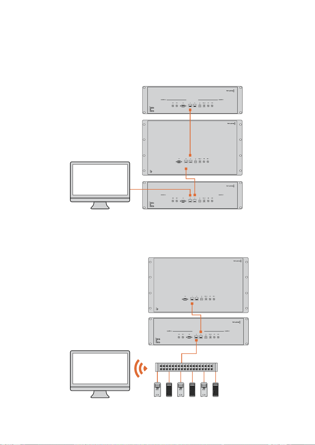
138Anschließen an ein Netzwerk
Anschlussdiagramm für direkte Ethernet-Verbindungen
Sie können den Ethernet-Port eines Computers ohne Umwege über einen Netzwerk-Switch direkt
mit Ihrer Einheit verbinden. Weitere Einheiten lassen sich dann miteinander verbinden. Das erspart
Ihnen das Verlegen mehrerer Kabel zum Netzwerk-Switch. Jede Einheit muss selbstständig mit
Strom versorgt werden.
Anschlussdiagramm für Ethernet-Netzwerk-Switches
Um mehrere Einheiten in Ihr vorhandenes Studionetzwerk einzubinden, brauchen Sie lediglich
eine Einheit an Ihren Netzwerk-Switch anzuschließen. Die übrigen Einheiten lassen sich dann
aneinanderreihen. Das erspart Ihnen das Verlegen mehrerer Kabel zum Netzwerk-Switch.
Jede Einheit muss selbstständig mit Strom versorgt werden.
SmartScope 4KDuo
SmartScope 4KDuo
Netzwerk-Switch
Ethernet
Nutzer-Computer

139Anpassen von Netzwerkeinstellungen
Anpassen von Netzwerkeinstellungen
Netzwerkeinstellungen
Gerätename
Damit jede Einheit im Netzwerk individuell erkannt werden kann, ist es empfehlenswert, jedem
SmartView oder SmartScope einen anderen Namen zuzuweisen, z.B. „Kamera 1 & 2“, „Multi-View-
Ausgabe“, „4K-Feeds“ usw.
Vergewissern Sie sich, dass Ihr Monitor per Ethernet oder USB verbunden ist, damit Sie seinen
Namen ändern können. Öffnen Sie Blackmagic SmartView Setup und klicken Sie anschließend auf
das Einstellungs-Icon unter dem Monitornamen. Klicken Sie auf der Einstellungsseite auf „Configure“
und ändern Sie im Abschnitt „Details“ den Namen Ihres Monitors. Sollte die Software einen
unzulässigen Namen erkennen, erscheint beim Tippen ein Warn-Icon neben dem Namen. Ist der
Name zulässig, erscheint ein grünes Häkchen. Mit der Enter-Taste auf Ihrer Computertastatur
bestätigen Sie die Namensänderung.
Netzwerkeinstellungen
Damit Sie in Blackmagic SmartView Setup Änderungen an den Netzwerkeinstellungen vornehmen
können, muss Ihr Blackmagic Monitor per USB an einen Computer angeschlossen sein.
Netzwerkeinstellungen lassen sich nicht über Ethernet vorgeben.
Standardmäßig wird dem SmartView oder SmartScope in Ihrem Netzwerk eine IP-Adresse über
DHCP zugewiesen.
Sollte kein DHCP-Server vorhanden sein, haben Sie die Möglichkeit, die Funktion „Internetfreigabe“
auf macOS bzw. die Funktion „Internetverbindungsfreigabe“ (ICS) auf Windows 8.1 oder Windows 10
zu aktivieren. Darüber werden DHCP-Adressen an alle direkt verbundenen Einheiten zugewiesen.
Die manuelle Zuweisung statischer IP-Adressen an einzelne Einheiten erübrigt sich damit. Sie
können die Funktion auch dann nutzen, wenn Ihr Computer über keine Internetverbindung verfügt.
Details zur Internetfreigabe finden Sie in der Hilfedokumentation zu macOS bzw. Windows
8.1 und 10.
Kann DHCP zur Konfiguration nicht verwendet werden, wählen Sie die Option „Static IP“. Fragen Sie
Ihren Systemadministrator nach einer freien IP-Adresse. Dadurch verhindern Sie IP-Konflikte in Ihrem
Netzwerk. Jede SmartView und SmartScope Einheit muss eine individuelle IP-Adresse sowie eine
gemeinsame Subnetzmaske zugewiesen werden. Der Standardwert im „Gateway“-Feld kann
beibehalten werden, es sei denn Sie möchten Ihre Einheiten an ein Netzwerk-Gateway wie einen
Internet-Router anschließen.
Werden keine SmartView oder SmartScope Monitore im Netzwerk gefunden, wurden den Einheiten
ggf. keine IP-Adressen via DHCP zugewiesen. In diesem Fall ist es notwendig, die
Netzwerkeinstellungen einer jeden Einheit manuell zu konfigurieren.
1 Verbinden Sie einen Blackmagic SmartView oder SmartScope Monitor per USB mit Ihrem
Computer und starten Sie Blackmagic SmartView Setup.
2 Der angeschlossene Monitor wird automatisch auf der Blackmagic SmartView Setup
Homepage angezeigt. Neben seinem Namen erscheint ein USB-Icon.
3 Passen Sie die Netzwerkeinstellungen des Monitors an.
4 Wiederholen Sie diese Schritte für alle weiteren Einheiten, denen keine IP-Adresse via
DHCP zugewiesen wurde.

140Anpassen von Netzwerkeinstellungen
Das USB-Icon neben dem Monitornamen deutet darauf hin, dass der
Monitor per USB mit Ihrem Computer verbunden ist. Eine USB-Verbindung
muss hergestellt werden, damit die Netzwerkeinstellungen
Ihres Blackmagic Monitors angepasst werden können
Für Netzwerkeinstellungen stehen die Optionen „DHCP“ oder „Static IP“
zur Verfügung und können ausschließlich via USB geändert werden
Hinzufügen eines Blackmagic Monitors
Wenn Sie die IP-Adresse eines SmartView oder SmartScope Duo 4K bereits kennen und diese nicht
automatisch auf der Blackmagic SmartView Setup Homepage erscheint, können Sie den Monitor
manuell hinzufügen. Das geht so:
1 Vergewissern Sie sich, dass Ihr Blackmagic Monitor per Ethernet verbunden ist. Um das
Fenster „Add a Blackmagic Monitor“ zu öffnen, klicken Sie in der linken unteren Ecke auf
das +-Icon.
2 Geben Sie die IP-Adresse des Monitors ein und klicken Sie auf „Add“.
3 Die Software verifiziert die Einheit nun und fügt sie zu den übrigen Blackmagic Monitoren
auf der Blackmagic SmartView Setup Homepage hinzu. Klicken Sie auf den Rechtspfeil,
um den neu hinzugefügten Monitor anzuzeigen.

141Arbeiten mit Tally
SmartView oder SmartScope Monitore können per Klick auf
das +-Icon und Eingabe der Monitor-IP-Adresse manuell zur
Liste der verbundenen Monitore hinzugefügt werden
Arbeiten mit Tally
Pinbelegung des Tally-Ports
Die Verwendung des Tally-Ports am SmartView oder SmartScope bleibt allein Ihnen überlassen.
Überspringen Sie dieses Kapitel, wenn Sie die Tally-Funktion nicht nutzen wollen.
SmartView und SmartScope Monitore verfügen über verschiedenfarbige Tally-Umrandungen in den
Farben Rot, Grün und Blau. Diese zeigen den Status eines Videosignals an, bspw. on air, Vorschau
oder Aufzeichnung.
Der 9-polige D-Sub-Port empfängt Signale von Mischern und Automationssystemen. Informationen
zur Verdrahtung des Tally-Ports für den Einsatz mit Ihrem Mischer oder Automationssystem finden
Sie im beigefügten Anschlussdiagramm.
Eine Beschreibung zur Verdrahtung des 9-poligen D-Sub-Ports ist zudem auf jeder Einheit
abgedruckt und zeigt die Pinbelegung für rote, grüne und blaue Tally-Umrandungen für jeden
Monitor an.
SmartView Duo mit grüner und roter Tally-Umrandung
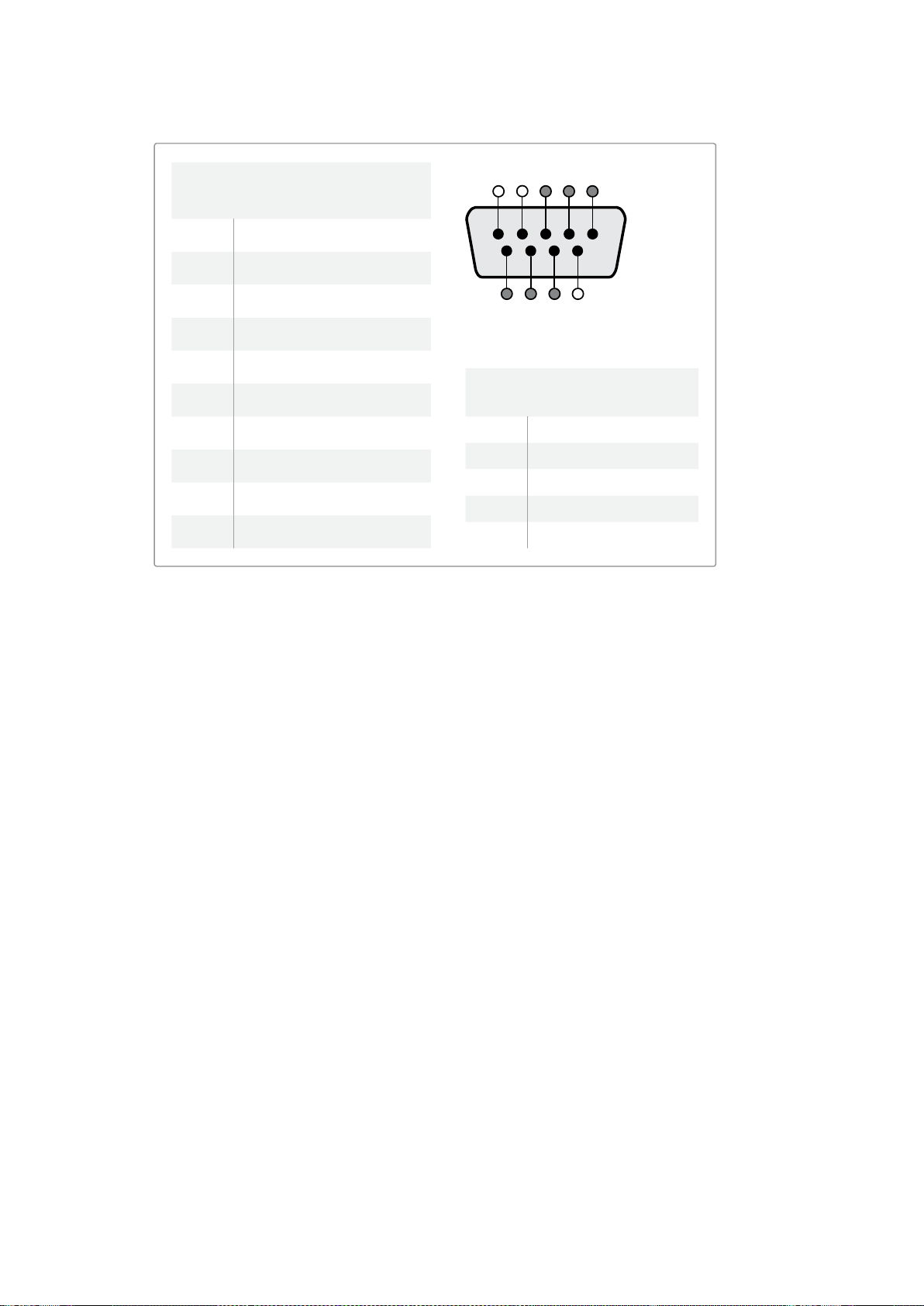
142Optimieren des Betrachtungswinkels
Optimieren des Betrachtungswinkels
Wenn SmartView Duo, SmartView HD oder SmartScope Monitore weit oben in einem Rack installiert
werden, möchten Sie die LCDs ggf. physikalisch invertieren, um den Betrachtungswinkel zu
optimieren. Wird eine Invertierung erkannt, richtet sich das LCD-Bild automatisch korrekt aus.
EinPozidriv-Schraubendreher der Größe 02 wird benötigt, um die Blende vom Gerät zu lösen.
Dieser Vorgang ist einfach, da die Rückseite des Gehäuses nicht geöffnet wird.
Im Folgenden wird beschrieben, wie das Gerät invertiert wird, während die korrekte Ausrichtung des
Blackmagic Design Logos und der Blende beibehalten werden. Wie bereits erwähnt wird hierfür ein
Pozidriv-Schraubendreher benötigt.
1 Entfernen Sie die oberen, unteren, linken und rechten Schrauben der Blende.
DerSmartView Duo und der SmartScope Duo 4K haben 10, der SmartView HD hat
18Schrauben.
2 Entfernen Sie die Blende wie abgebildet von der Rückseite des Gehäuses.
3 Invertieren Sie die Rückseite des Gehäuses.
4 Setzen Sie die Blende auf die invertierte Rückseite des Gehäuses auf.
5 Setzen Sie die Schrauben wieder ein und ziehen Sie sie fest.
Ihr SmartView oder SmartScope ist nun bereit zur Montage weit oben im Rack. Ist der SmartView mit
dem Rack verschraubt, bleibt auch dann der optimale Betrachtungswinkel erhalten, wenn der
Monitor Stöße abbekommt, da er keine externen Regler oder Knöpfe hat, die sich lösen könnten.
SmartView Duo und SmartScope Duo 4K
Pinbelegung des Tally-Ports
Pin Funktion
1 Monitor 1 Rot
2 Monitor 1 Grün
3 Monitor 1 Blau
4 Erdung
5 Erdung
6 Erdung
7 Monitor 2 Rot
8 Monitor 2 Grün
9 Monitor 2 Blau
SmartView HD und SmartView 4K
Pinbelegung des Tally-Ports
Pin Funktion
1 Rot
2 Grün
3 Blau
4 Erdung
5 4 3 2 1
9
8
7 6
SmartView Tally-Port
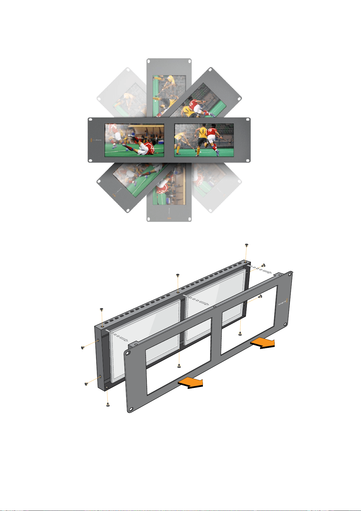

144Informationen für Entwickler (Englisch)
Informationen für Entwickler (Englisch)
Developing Custom Software Using Blackmagic Design Hardware
The Blackmagic SmartView Ethernet Protocol allows developers to remotely control Blackmagic
SmartView and SmartScope hardware with their own custom software. The Blackmagic SmartView
Ethernet Protocol is a text-based status and control protocol.
Downloading the Free SmartView EthernetProtocol
The Blackmagic SmartView Ethernet Protocol is free. It is included in this SmartView & SmartScope
manual and can be downloaded from http://www.blackmagicdesign.com/de/support
Joining the Blackmagic Design Developer List
The Blackmagic Developer mailing list is designed for technical questions regarding technologies
used by Blackmagic Design, e.g., QuickTime, Core Media, DirectShow, codecs, APIs, SDKs, etc.
Thefree mailing list is a forum where developers can discuss ideas and problems with other
developers. Any subscriber may reply and the Blackmagic Design engineers may also respond
when appropriate. You can subscribe to the mailing list at: http://lists.blackmagicdesign.com/
mailman/listinfo/bmd-developer
In some cases, we might request a brief outline of the software you are developing if it is not
immediately obvious from your domain name that your organization develops video software. Please
don’t take offence as we’re simply trying to keep the list free of spam and viruses as well as end-user
customers asking non-development questions, employment agents or sales people trying to
promote products on the list. The list is just for developers.
Contacting Blackmagic Design DeveloperAssistance
You can also contact us via developer@blackmagicdesign.com if you have any developer related
questions or wish to ask questions off the list.
Blackmagic 2K Format – Overview
Blackmagic Design products support 3G-SDI video, which allows twice the data rate of traditional
HD-SDI video. We thought it would be a really nice idea to add 2K film support,
via 3G-SDI technology, so we could simplify feature film workflows. With the popularity of
Blackmagic Design editing systems worldwide, now thousands of people can benefit from
a feature film workflow revolution.
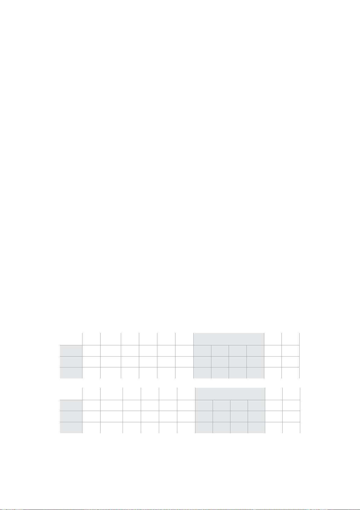
145Informationen für Entwickler (Englisch)
This information includes everything product developers need to know for building native 2K SDI
equipment. Of course, all Blackmagic products can be updated, so if the television industry adopts
an alternative SDI-based film standard, we can add support for that too!
Frame Structure
Transmitted at 23.98, 24 or 25 frames per second as a Progressive Segmented Frame.
Active video is 2048 pixels wide by 1556 lines deep.
Total lines per frame : 1650
Active words per line are 1535. One word consists of a 10-bit sample for each of the four
data streams, i.e., a total of 40 bits. See the diagram named Blackmagic 2K Format
- Data Stream Format.
Total active lines : 1556
Total words per line : 1875 for 23.98/24Hz and 1800 for 25Hz.
Fields per frame : 2, 825 lines each
Active lines located on lines 16-793 (field 1) and 841-1618 (field 2).
Transport Structure
Based on SMPTE 372M Dual Link mapping and SMPTE 425M-B support for mapping SMPTE
372M into a single 3 Gb/s link.
Timing reference signals, line number and line CRC insertion is the same as above.
During active video, 10-bit Red, Green and Blue data is sent in the following sequence:
Optional ancillary data is inserted into both virtual interfaces.
At present, only audio data is included: as per standard HD audio insertion (SMPTE S299M)
the audio data packets are carried on data stream two and audio control packets are carried
on data stream one.
Data stream 1: Green_1, Green_2, Green_3, Green_5...Green_2047
Data stream 2: Blue_1, Blue_2, Green_4, Blue_5...Green_2048.
Data stream 3: Red_1, Blue_3, Blue_4, Red_5...Blue_2048.
Data stream 4: Red_2, Red_3, Red_4, Red_6...Red_2048.
Blackmagic 2K Format – Vertical Timing Reference
This diagram shows the vertical timing details with line numbers and Field, Vertical and Horizontal
bits for the Timing Reference Signal codes.
Field 1 Active
F 1 0 0 0 0 0 0 0 0 0 0 0
V 1 1 1 1 1 1 0 0 0 0 1 1
LINE # 1650 1 2 ... 14 15 16 ... 792 793 ... 825
Field 2 Active
F 0 1 1 1 1 1 1 1 1 1 1 1
V 1 1 1 1 1 1 0 0 0 0 1 1
LINE # 825 826 827 ... 839 840 841 ... 1617 1618 ... 1650
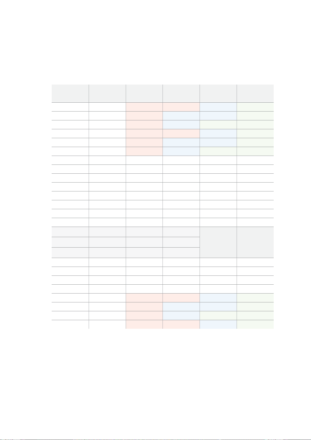
146Informationen für Entwickler (Englisch)
Blackmagic 2K Format – DataStream Format
This diagram shows the data stream formats around the optional ancillary data section of the horizontal line.
Note that each active pixel takes up three samples.
Data Stream 1
G2041
G2042
G2043
G2045
G2046
G2047
EAV(3FFh)
EAV(000h)
EAV(000h)
EAV(XYZh)
LN0
LN1
CRC0
CRC1
ANC/Audio Data
SAV(3FFh)
SAV(000h)
SAV(000h)
SAV(XYZh)
G1
G2
G3
G5
Data Stream 2
B2041
B2042
G2044
B2045
B2046
G2048
EAV(3FFh)
EAV(000h)
EAV(000h)
EAV(XYZh)
LN0
LN1
CRC0
CRC1
ANC/Audio Data
SAV(3FFh)
SAV(000h)
SAV(000h)
SAV(XYZh)
B1
B2
G4
B5
Data Stream 3
R2041
B2043
B2044
R2045
B2047
B2048
EAV(3FFh)
EAV(000h)
EAV(000h)
EAV(XYZh)
LN0
LN1
CRC0
CRC1
040
…
040
SAV(3FFh)
SAV(000h)
SAV(000h)
SAV(XYZh)
R1
B3
B4
R5
Data Stream 4
R2042
R2043
R2044
R2046
R2047
R2048
EAV(3FFh)
EAV(000h)
EAV(000h)
EAV(XYZh)
LN0
LN1
CRC0
CRC1
200
…
200
SAV(3FFh)
SAV(000h)
SAV(000h)
SAV(XYZh)
R2
R3
R4
R6
Word#
23.98/24 PsF
1870
1871
1872
1873
1874
1875
1
2
3
4
5
6
7
8
9
…
335
336
337
338
339
340
341
342
343
Word#
25 PsF
1795
1796
1797
1798
1799
1800
1
2
3
4
5
6
7
8
9
…
260
261
262
263
264
265
266
267
268

147Informationen für Entwickler (Englisch)
Blackmagic SmartView Ethernet Protocol v1.3
Summary
The Blackmagic SmartView Ethernet Protocol is a text-based status and control protocol, very similar
in structure to the Videohub protocol, that is accessed by connecting to TCP port 9992 on a
SmartView or SmartScope device.
Upon connection, the SmartView or SmartScope device sends a complete dump of the state
of the device. After the initial dump, state changes are sent asynchronously.
The device sends information in blocks which have an identifying header, followed by a colon.
Ablock can span multiple lines and is terminated by a blank line.
To be resilient to future protocol changes, clients should ignore blocks they do not recognize, up to
the trailing blank line. Within recognized blocks, clients should ignore lines they do not recognize.
Version 1.3 of the Blackmagic SmartView Ethernet
Protocol was released with SmartView 1.3 software.
Protocol Preamble
The first block sent by the SmartView Server is always the protocol preamble:
PROTOCOL PREAMBLE:↵
Version: 1.3 ↵
↵
The version field indicates the protocol version. When the protocol is changed in a compatible way,
the minor version number will be updated. If incompatible changes are made, the major version
number will be updated.
Device Information
The next block contains general information about the connected SmartView or SmartScope device.
SMARTVIEW DEVICE:↵
Model: SmartView Duo↵
Hostname: stagefront.studio.example.com↵
Name: StageFront↵
Mo nitor s: 2↵
Inverted: false↵
↵
This example shows the output for a SmartView Duo device, which has two LCDs.
The INVERTED flag indicates whether the device has detected that it has been mounted in an
inverted configuration to optimize LCD viewing angle.
Legend
↵ carriage return
… and so on

148Informationen für Entwickler (Englisch)
Network Configuration
The next block shows the TCP/IP networking configuration:
NETWORK:↵
Dynamic IP: true↵
Static address: 192.168.2.2↵
St atic netm as k: 255.255.255.0↵
St atic gatew ay: 192.168.2.1↵
C u rr e nt ad d r e ss: 192.168.1.101↵
C u rr e nt netm a sk: 255.255.255.0↵
C u rr e nt g ate w ay: 192.168.1.1↵
↵
The network settings prefixed with CURRENT show the active TCP/IP settings, and are read-only.
The CURRENT settings reflect either the DHCP or Static configuration, depending on the
DYNAMIC IP flag.
Changing Networking Settings
The network can be configured to use either DHCP or a static configuration. To enable DHCP:
NETWORK:↵
Dynamic IP: true↵
↵
To set a fixed IP address, supply all static parameters, thus:
NETWORK:↵
Dynamic IP: false↵
Static address: 192.168.2.2↵
St atic netm as k: 255.255.255.0↵
St atic gatew ay: 192.168.2.1↵
↵
The parameters with the CURRENT prefix are read-only, and show the active configuration,
regardless of the static or dynamic setting.
Changing the device name, or any network settings, will cause the IP connection to be dropped.
The device will restart its networking and advertise its new name on the network.
Changing Monitor Settings
The display settings for each monitor are specified individually. One or more parameters can
be modified at the same time and multiple settings can be supplied in one block.
The valid range for numeric values is 0-255. The CONTRAST and SATURATION properties are
zero-centered, so the normal value is 127, such that the displayed picture is the same as the original.
A value greater than 127 in either channel will cause the contrast or saturation to be increased,
and similarly a value less than 127 will cause a decrease.
For example, to set the brightness to 50% and desaturate the image to Black & White:
MONITOR A:↵
Brightness: 127↵
Saturation: 0↵
↵

149Informationen für Entwickler (Englisch)
Displaying SD in 16:9
The following command sets standard definition video to display in 16:9:
MONITOR A:↵
WidescreenSD: ON↵
Displaying SD in 4:3
The following command sets standard definition video to display in 4:3:
MONITOR A:↵
WidescreenSD: OFF↵
Identification and Tally Settings
The Identify flag is transient, and will cause a white border to be displayed around the entire picture
for a duration of 15 seconds, after which it will be reset. This feature is primarily aimed at identifying
which monitor is currently being configured when it is mounted in a rack comprising multiple units.
To turn on:
MONITOR A:↵
Ide ntify: tr u e↵
↵
The IDENTIFY border will temporarily override any other border setting in effect.
The BORDER property can be used to programmatically set the soft Tally colored borders to one
of the primary colors: RED, GREEN, BLUE, WHITE or NONE. This setting can be overridden by the
electrical Tally signals at the DB-9 input on the device itself. For example, to set the soft
Tally to green:
MONITOR B:↵
Border: green↵
↵
The hard wired tally will always override the soft tally. The full state report will always show the
current valid border.
SmartScope Settings
On SmartScope Duo 4K, each monitor can be set to display a different scope. The values for
activating specific scopes are mapped as follows:
AudioDbfs
AudioDbvu
Histogram
ParadeRGB
ParadeYUV
Picture (This is the same as Video Monitor)
Vector100
Vector75
WaveformLuma
MONITOR A:↵
ScopeMode: Picture↵
↵
In the example above, Monitor A has been set as a video monitor.

150Informationen für Entwickler (Englisch)
Displaying SD in 16:9
The set Video Monitor mode to display standard definition video in 16:9:
MONITOR A:↵
ScopeMode: Picture↵
WidescreenSD: ON↵
Displaying SD in 4:3
To set Video Monitor mode to display standard definition video in 4:3:
MONITOR A:↵
ScopeMode: Picture↵
WidescreenSD: OFF↵
When setting one of SmartScope Duo 4K’s monitors to audio metering, you can also select which
channels to show. The values for selecting which audio channels are mapped in the following way:
0: Channels 1 and 2
1: Channels 3 and 4
2: Channels 5 and 6
3: Channels 7 and 8
4: Channels 9 and 10
5: Channels 11 and 12
6: Channels 13 and 14
7: Channels 15 and 16
MONITOR B:↵
ScopeMode: AudioDbvu↵
AudioChannel: 0↵
↵
In the example above, Monitor B has been selected to display Audio Metering in Dbvu with audio
channels 1 and 2 selected for the phase meter.
Selecting LUTs for SmartView 4K
To select 3D LUTs using SmartView 4K:
MONITOR A:↵
LUT: 0 LUT 1
1 LUT 2
NONE DISABLE
↵
↵

151Hilfe
Hilfe
Hilfestellung
Es gibt vier Möglichkeiten, sich Hilfe zu holen.
1 Holen Sie sich die neuesten Informationen im Blackmagic Design Support-Center unter
www.blackmagicdesign.com/de/support.
2 Rufen Sie Ihren Blackmagic Design Händler an.
Ihr lokaler Händler verfügt über die aktuellsten Informationen von Blackmagic Design und
sollte in der Lage sein, Ihnen sofort behilflich zu sein. Darüber hinaus empfehlen wir Ihnen,
sich über die Support-Optionen Ihres Händlers zu informieren, da dieser Ihnen
entsprechend Ihrer Workflow-Anforderungen unter die Arme greifen kann.
3 Oder kontaktieren Sie uns mit Ihren Fragen per E-Mail, indem Sie unter
www.blackmagicdesign.com/de/support auf „Senden Sie uns eine E-Mail“ klicken.
4 Rufen Sie eine Blackmagic Design Support-Stelle an. Klicken Sie hierfür unten auf der
Support-Seite auf „Finden Sie Ihr lokales Support-Team“.
Bitte stellen Sie uns so viele Informationen und Systemspezifikationen zur Verfügung wie Sie
können, damit wir schnellstmöglich auf Ihr technisches Problem eingehen können.
152Gesetzliche Vorschriften undSicherheitshinweise
Gesetzliche Vorschriften
undSicherheitshinweise
Gesetzliche Vorschriften
Entsorgung von elektrischen und elektronischen Geräten innerhalb der Europäischen Union
Das auf dem Produkt abgebildete Symbol weist darauf hin, dass dieses Gerät nicht
zusammen mit anderen Abfallstoffen entsorgt werden darf. Altgeräte müssen daher zur
Wiederverwertung an eine dafür vorgesehene Sammelstelle übergeben werden.
Mülltrennung und Wiederverwertung von Altgeräten tragen zum nachhaltigen Umgang
mit natürlichen Ressourcen bei. Gleichzeitig wird sichergestellt, dass die
Wiederverwertung nicht zulasten der menschlichen Gesundheit und der Umwelt geht.
Weitere Informationen zur Entsorgung von Altgeräten sowie zu den Standorten der
zuständigen Sammelstellen erhalten Sie von Ihren örtlichen Müllentsorgungsbetrieben
sowie vom Händler, bei dem Sie dieses Produkt erworben haben.
Dieses Gerät wurde geprüft und entspricht den Grenzwerten für Digitalgeräte der
Klasse A gemäß Abschnitt 15 der FCC-Bestimmungen für Funkentstörung. Diese
Grenzwerte dienen dem angemessenen Schutz vor schädlichen Störungen bei Betrieb
des Geräts in einer kommerziellen Einrichtung. Geräte dieser Art erzeugen und
verwenden Hochfrequenzen und können diese auch ausstrahlen. Bei Nichteinhaltung
der Installations- und Gebrauchsvorschriften können sie zu Störungen beim
Rundfunkempfang führen. Der Betrieb solcher Geräte im Wohnbereich führt mit großer
Wahrscheinlichkeit zu Funkstörungen. In diesem Fall kann vom Betreiber verlangt
werden, selbst für die Beseitigung solcher Störungen aufzukommen.
Der Betrieb unterliegt den folgenden zwei Bedingungen:
1 Dieses Gerät darf keine schädigenden Störungen hervorrufen.
2 Dieses Gerät muss alle Störungen annehmen, einschließlich Störungen, die
einen unerwünschten Betrieb zur Folge haben.
Sicherheitshinweise
Dieses Gerät muss an ein vorschriftsmäßig geerdetes Stromnetz angeschlossen werden.
Um das Risiko eines elektrischen Schlages zu verringern, setzen Sie das Gerät weder
Tropfen noch Spritzern aus.
Das Gerät eignet sich für den Einsatz in tropischen Gebieten mit einer
Umgebungstemperatur von bis zu 40ºC.
Achten Sie auf eine ausreichende Luftzufuhr um das Gerät herum, sodass die Belüftung
nicht eingeschränkt wird.
Achten Sie bei der Installation im Rack darauf, dass die Luftzufuhr nicht durch andere
Geräte eingeschränkt wird.
Es befinden sich keine durch den Anwender zu wartenden Teile im Inneren des Gehäuses.
Wenden Sie sich für die Wartung an ein Blackmagic Design Service Center in Ihrer Nähe.
Nicht in Höhen von über 2000m über dem Meeresspiegel einsetzen.
Dieses Produkt bietet die Möglichkeit, ein Small-Form-Factor-Glasfasermodul (SFP)
anzuschließen. Es dürfen nur SFP-Glasfasermodule der Laserklasse 1 eingesetzt werden.
Blackmagic Design empfiehlt die nachstehenden SFP-Module:
3G-SDI: PL-4F20-311C
6G-SDI; PL-8F10-311C

153Garantie
Warnhinweise für autorisiertes Wartungspersonal
Vergewissern Sie sich, dass die Verbindung zum Stromnetz vor Beginn der
Wartung getrennt wurde.
Vorsicht– Doppelpol/Neutrale Sicherung
Die in diesem Gerät enthaltenen Außen- und Neutralleiter sind beide durch
eineSicherung geschützt. Daher ist das Gerät für den Anschluss an das
IT-Energieverteilungssystem in Norwegen geeignet.
Garantie
12 Monate eingeschränkte Garantie
Für dieses Produkt gewährt die Firma Blackmagic Design eine Garantie auf Material- und
Verarbeitungsfehler von 12 Monaten ab Kaufdatum. Sollte sich ein Produkt innerhalb dieser
Garantiezeit als fehlerhaft erweisen, wird die Firma Blackmagic Design nach ihrem Ermessen das
defekte Produkt entweder ohne Kostenerhebung für Teile und Arbeitszeit reparieren oder Ihnen das
defekte Produkt ersetzen.
Zur Inanspruchnahme der Garantieleistungen müssen Sie als Kunde Blackmagic Design über den
Defekt innerhalb der Garantiezeit in Kenntnis setzen und die entsprechenden Vorkehrungen für die
Leistungserbringung treffen. Es obliegt dem Kunden, für die Verpackung und den bezahlten Versand
des defekten Produkts an ein spezielles von Blackmagic Design benanntes Service Center zu
sorgen und hierfür aufzukommen. Sämtliche Versandkosten, Versicherungen, Zölle, Steuern und
sonstige Abgaben im Zusammenhang mit der Rücksendung von Waren an uns, ungeachtet des
Grundes, sind vom Kunden zu tragen.
Diese Garantie gilt nicht für Mängel, Fehler oder Schäden, die durch unsachgemäße Handhabung
oder unsachgemäße oder unzureichende Wartung und Pflege verursacht wurden. Blackmagic
Design ist im Rahmen dieser Garantie nicht verpflichtet, die folgenden Serviceleistungen zu
erbringen: a) Behebung von Schäden infolge von Versuchen Dritter, die Installation, Reparatur oder
Wartung des Produkts vorzunehmen, b) Behebung von Schäden aufgrund von unsachgemäßer
Handhabung oder Anschluss an nicht kompatible Geräte, c) Behebung von Schäden oder
Störungen, die durch die Verwendung von nicht Blackmagic-Design-Ersatzteilen oder
-Verbrauchsmaterialien entstanden sind, d) Service für ein Produkt, das verändert oder in andere
Produkte integriert wurde, sofern eine solche Änderung oder Integration zu einer Erhöhung des
Zeitaufwands oder zu Schwierigkeiten bei der Wartung des Produkts führt. ÜBER DIE IN DIESER
GARANTIEERKLÄRUNG AUSDRÜCKLICH AUFGEFÜHRTEN ANSPRÜCHE HINAUS ÜBERNIMMT
BLACKMAGIC DESIGN KEINE WEITEREN GARANTIEN, WEDER AUSDRÜCKLICH NOCH
STILLSCHWEIGEND. DIE FIRMA BLACKMAGIC DESIGN UND IHRE HÄNDLER LEHNEN JEGLICHE
STILLSCHWEIGENDEN GARANTIEN IN BEZUG AUF AUSSAGEN ZUR MARKTGÄNGIGKEIT UND
GEBRAUCHSTAUGLICHKEIT FÜR EINEN BESTIMMTEN ZWECK AB. DIE VERANTWORTUNG VON
BLACKMAGIC DESIGN, FEHLERHAFTE PRODUKTE ZU REPARIEREN ODER ZU ERSETZEN, IST DIE
EINZIGE UND AUSSCHLIESSLICHE ABHILFE, DIE GEGENÜBER DEM KUNDEN FÜR ALLE
INDIREKTEN, SPEZIELLEN, NEBEN- ODER FOLGESCHÄDEN ZUR VERFÜGUNG GESTELLT WIRD,
UNABHÄNGIG DAVON, OB BLACKMAGIC DESIGN ODER DER HÄNDLER VON DER MÖGLICHKEIT
SOLCHER SCHÄDEN ZUVOR IN KENNTNIS GESETZT WURDE. BLACKMAGIC DESIGN IST NICHT
HAFTBAR FÜR JEGLICHE WIDERRECHTLICHE VERWENDUNG DER GERÄTE DURCH DEN
KUNDEN. BLACKMAGIC HAFTET NICHT FÜR SCHÄDEN, DIE SICH AUS DER VERWENDUNG DES
PRODUKTS ERGEBEN. NUTZUNG DES PRODUKTS AUF EIGENE GEFAHR.
© Copyright 2018 Blackmagic Design. Alle Rechte vorbehalten. „Blackmagic Design“, „DeckLink“, „HDLink“, „Workgroup
Videohub“, „Multibridge Pro“, „Multibridge Extreme“, „Intensity“ und „Leading the creative video revolution“ sind eingetragene
Warenzeichen in den USA und in anderen Ländern. Alle anderen Unternehmens- und Produktnamen sind möglicherweise
Warenzeichen der jeweiligen Firmen, mit denen sie verbunden sind.


Bienvenido
Ojalá compartas nuestro sueño de transformar la industria televisiva en un sector verdaderamente
creativo, donde todos tengan acceso a la mejor calidad en materia de imagen.
La supervisión de señales audiovisuales es fundamental en todo tipo de instalaciones. El monitor
SmartView 4K presenta un diseño elegante de 6U con una pantalla LCD para monitorizar imágenes
UHD y un panel de control que permite modificar ajustes con rapidez. La versión SmartView
HD incluye una pantalla LCD de 17 pulgadas en un tamaño de 6U y menos de 4centímetros de
espesor. Por su parte, el modelo SmartView Duo cuenta con dos pantallas LCD de 8 pulgadas
completamente independientes en un tamaño de 3U y menos de 4 centímetros de espesor,
mientras que la versión SmartScope Duo 4K ofrece las mismas características y ofrece instrumentos
de medición para ajustar los diversos aspectos de la señal sobre la marcha. Todos los monitores
SmartView brindan conectividad SDI 3G y admiten imágenes en definición SD, HD y 2K. A su vez,
cabe destacar que los modelos SmartScope Duo 4K y SmartView 4K incluyen conexiones SDI 6G y
12G, respectivamente, que facilitan la monitorización de material UHD 4K.
Los dispositivos están diseñados para funcionar de forma inmediata una vez adquiridos, y al
mismo tiempo nuestro programa utilitario gratuito ofrece al usuario una herramienta de
configuración fácil e intuitiva.
El manual de instrucciones contiene toda la información necesaria para instalar el producto, aunque
recomendamos consultar a un técnico si no estás seguro de lo que es una dirección IP o no tienes
demasiados conocimientos sobre redes informáticas. A pesar de que la instalación de los distintos
modelos SmartView y SmartScope es sencilla, quizás sea necesario modificar algunos ajustes una
vez finalizado este procedimiento.
Estimamos que puede completarse en aproximadamente 5 minutos. En nuestra página de soporte
técnico encontrarás la versión más reciente de este manual y del software para la línea de monitores
SmartView. Por último, no olvides registrarte al descargar las actualizaciones, a fin de que podamos
mantenerte informado sobre nuevos lanzamientos. Trabajamos constantemente para desarrollar
herramientas innovadoras y superarnos, de modo que nos encantaría conocer tu opinión.
Grant Petty
Director ejecutivo de Blackmagic Design

Índice
SmartView y SmartScope
Primeros pasos 157
SmartView y SmartScope 157
Conexión de fuentes 158
Conexión de equipos informáticos 158
Instalación del programa SmartView Setup 159
Uso del programa SmartView Setup 160
Actualizaciones 160
Ajustes del monitor 160
SmartView 4K 163
Introducción 163
Botones del panel de control 164
Aplicar LUT 3D con SmartView Setup 166
SmartScope Duo 4K 167
¿Qué es Blackmagic SmartScope? 167
Imágenes 167
Forma de onda 168
Vectorscopio 169
Luminancia y crominancia 171
Histograma 172
Medición del audio 173
Conexión a redes 174
Conexión Ethernet directa 175
Conmutador de red 175
Ajustes de red 177
Configuración de la red 177
Agregar monitores a la red 178
Sistemas de señalización 179
Conexión 179
Mejora del ángulo de visión 180
Información para desarrolladores 182
Formato 2K de Blackmagic – Información general 182
Formato 2K de Blackmagic – Referenciadetemporizaciónvertical 183
Formato 2K de Blackmagic – Transmisión de datos 184
Protocolo de Ethernet Blackmagic SmartView v1.3 185
Ayuda 189
Información sobre normativas yseguridad 190
Garantía 191
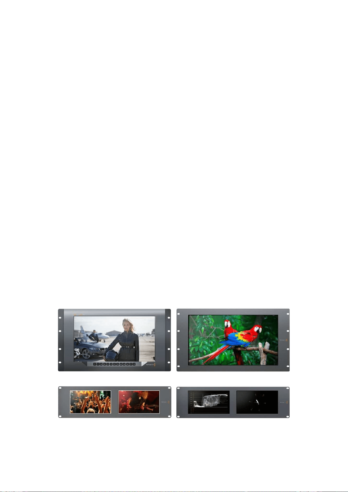
157Primeros pasos
Primeros pasos
SmartView y SmartScope
Los monitores SmartView son ideales para instalaciones donde es necesario supervisar señales
audiovisuales mediante equipos en bastidores. Para comenzar a usarlos, solo es necesario
enchufarlos a una toma de corriente y conectar una fuente SDI.
El modelo SmartView 4K cuenta con una pantalla LCD de 15.6 pulgadas que permite supervisar
imágenes SD, HD o UHD en su resolución original. Los botones del panel frontal permiten
seleccionar distintas entradas con facilidad, ajustar el brillo de la pantalla, comprobar el ruido en el
canal azul, ver la información contenida en el intervalo de supresión y aplicar tablas de conversión,
entre otras funciones.
El modelo SmartView HD dispone de una pantalla LCD de 17 pulgadas que resulta ideal para
monitorizar contenidos con absoluta confianza.
Por su parte, la versión SmartView Duo incluye dos monitores para ver dos señales diferentes.
A modo de ejemplo, una pantalla puede mostrar imágenes YUV 4:2:2, y la otra en contenidos
formato RGB 4:4:4.De esta forma, es posible ver señales NTSC y PAL simultáneamente. Basta con
conectar solo un cable SDI a cada monitor.
El modelo SmartScope Duo 4K ofrece las mismas funciones de la versión SmartView Duo y además
muestra la onda de la señal, la crominancia y otras representaciones gráficas para supervisar
diversos parámetros audiovisuales en tiempo real. Cabe destacar asimismo que admite
imágenes UHD 4K.
Las entradas SDI de ambos dispositivos detectan automáticamente señales SD, HD o 3G, e incluso
con resolución 2K. Además, el modelo SmartView 4K es compatible con formatos 2160p60, gracias
a su conectividad SDI12G. Por otro lado, la tecnología SDI6G de la versión SmartScope Duo4K
permite detectar automáticamente señales UHD 4K.
La conexión Ethernet brinda la posibilidad de modificar los ajustes de varias unidades en forma
remota desde un equipo informático, lo cual evita tener que conectarlo a cada una de ellas cuando
es preciso cambiar la configuración.
Esto es todo lo que necesita saber para comenzar. Continúe leyendo para obtener más información
acerca de los dispositivos y su conexión a una red Ethernet.
SmartView 4K SmartView HD
SmartView Duo SmartScope Duo 4K
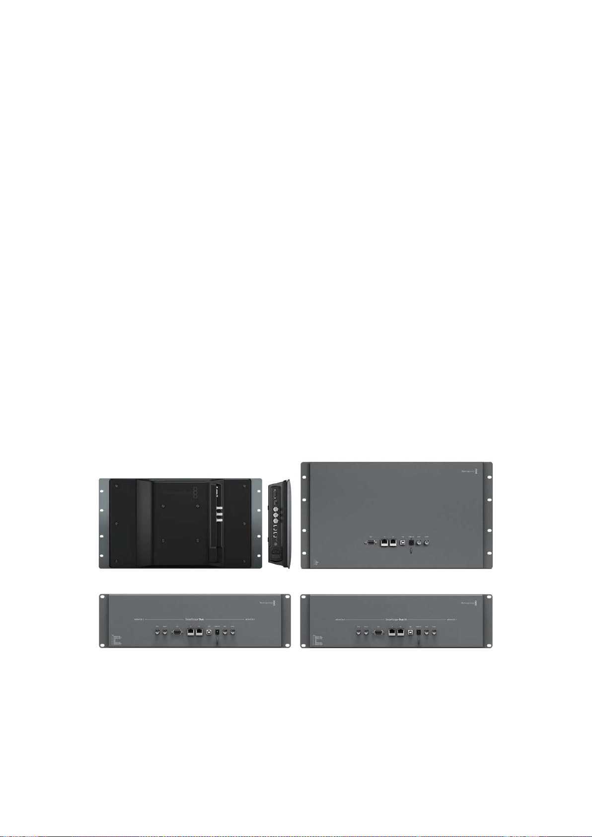
158Primeros pasos
Conexión de fuentes
Los modelos SmartView y SmartScope incluyen conectores BNC convencionales que permiten
emplearlos con equipos SDI, tales como mezcladores, cámaras, grabadores y tarjetas de captura.
Visualización de imágenes
Es sumamente sencillo ver las imágenes. Basta con encender el dispositivo y conectar una fuente
a una entrada SDI. A continuación, estas deberían visualizarse en forma inmediata. Tanto la entrada
SDI como las conexiones derivadas detectan automáticamente señales en definición SD, HD o 2K.
Cabe mencionar además que los modelos SmartView 4K y SmartScope Duo 4K son compatibles
con imágenes UHD 4K.
Cuando no hay una fuente conectada al dispositivo, la unidad de retroiluminación se apagará para
ahorrar energía. Esta se encenderá nuevamente al detectarse una señal compatible.
Conexión de unidades en serie
Cada modelo SmartView y SmartScope dispone de una entrada SDI independiente y una salida
derivada que permite conectar varias unidades en serie.
1 Encienda la unidad 1. Conecte una fuente a una entrada SDI. La imagen debería verse
inmediatamente.
2 Encienda la unidad 2. Conecte la salida derivada de la unidad 1 a una entrada SDI de la
unidad 2 mediante un cable SDI.
Es posible conectar tantas unidades como sea necesario.
Al supervisar la onda de la señal mediante el modelo SmartScope Duo 4K, es aconsejable conectar
el monitor 1 al monitor 2 para que ambos muestren la misma señal.
Una vez que la imagen se ve en la pantalla, es posible modificar los ajustes de los dispositivos
o seleccionar una de las representaciones gráficas disponibles en el modelo SmartScope Duo 4K
mediante el programa SmartView Setup. Cabe mencionar que esta aplicación también permite
aplicar tablas de conversión tridimensionales en la versión SmartView 4K.
SmartView 4K SmartView HD
SmartView Duo
SmartScope Duo 4K
Conexión de equipos informáticos
Conecte su PC al monitor mediante un cable USB 2.0 e instale el programa SmartView Setup para
configurar el dispositivo.
La conexión USB permite además instalar actualizaciones para el sistema operativo interno
descargadas desde nuestro sitio web. Estas ofrecen funciones adicionales, así como compatibilidad
con nuevos formatos y equipos. El programa SmartView Setup puede instalarse en sistemas
operativos macOS y Windows.
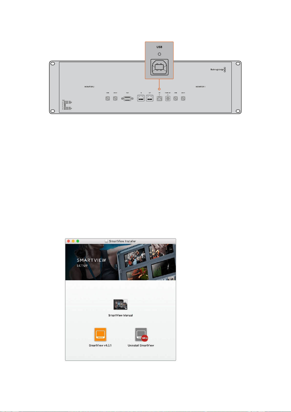
159Primeros pasos
Instalación del programa SmartView Setup
Esta aplicación funciona en las últimas versiones Sierra y High Sierra del sistema operativo macOS,
así como en versiones de 64 bits de Windows 8.1 y 10 con las actualizaciones más recientes
instaladas. El programa también puede instalarse en varios equipos informáticos que formen parte
de una red.
La tarjeta SD suministrada con el dispositivo contiene un instalador, aunque recomendamos visitar
nuestro sitio web para descargar la versión más reciente.
Instalación en macOS:
Acceda al contenido de la tarjeta o de la imagen descargada y haga doble clic en el ícono de
instalación. Se creará una carpeta en Aplicaciones con el programa, el desinstalador, que permite
borrar versiones previas de la aplicación, y varios documentos que incluyen este manual y otros
datos con relación al dispositivo.
Instalación en Windows:
Acceda al contenido de la tarjeta SD o del archivo comprimido descargado y haga doble clic en
el instalador. Siga las instrucciones que aparecen en la pantalla para instalar el programa.
Para instalar el programa en macOS, abra el archivo SmartView.dmg
descargado o incluido en la tarjeta SD que viene con el dispositivo.
A continuación, haga doble clic en el ícono de instalación.
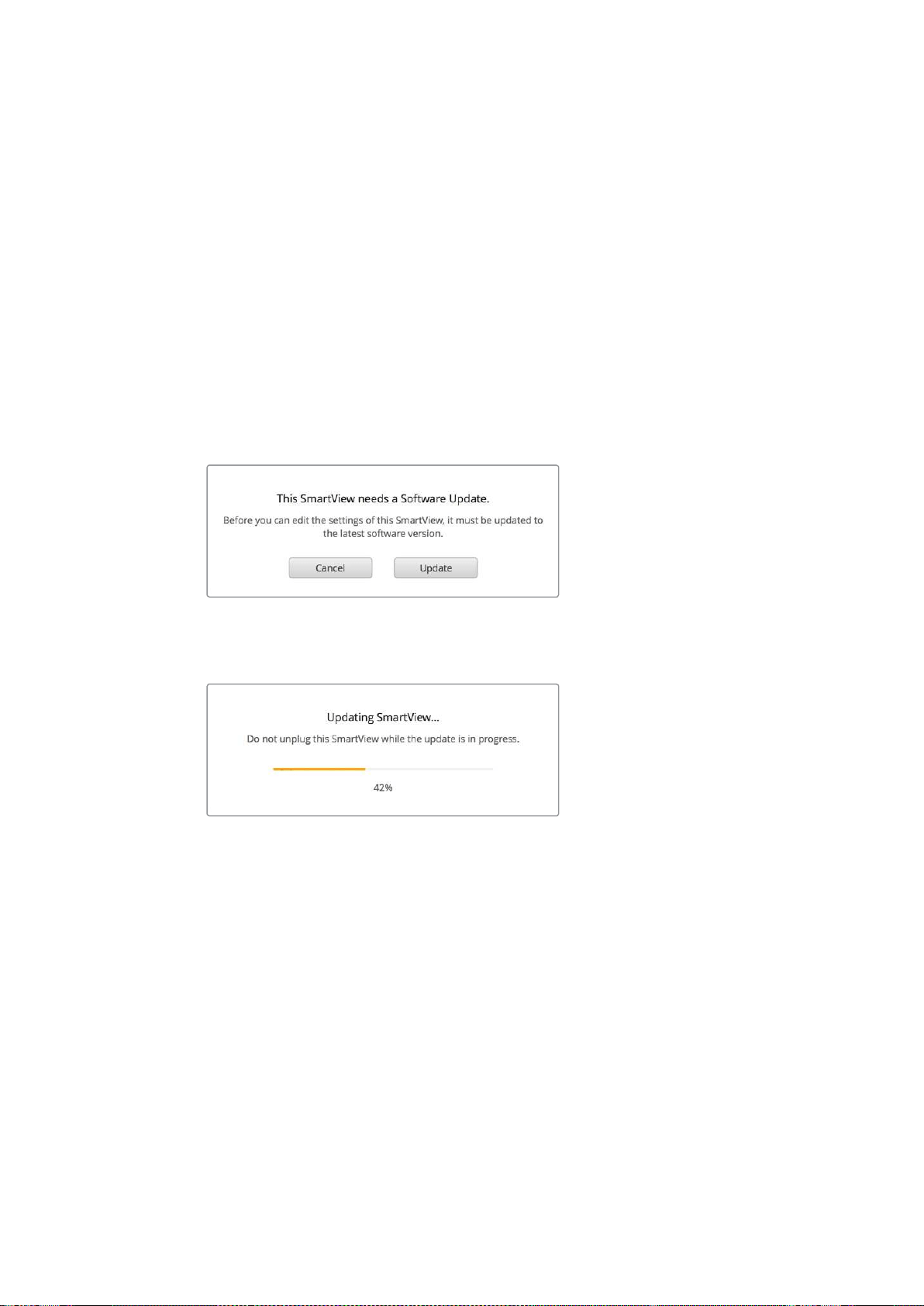
160Uso del programa SmartView Setup
Uso del programa SmartView Setup
Actualizaciones
Ejecute el programa una vez instalado y haga clic en el ícono de configuración situado debajo
del nombre del monitor. El programa le solicitará que actualice el sistema operativo interno del
dispositivo si es necesario. Para ello, siga los pasos descritos a continuación.
1 Conecte su PC al dispositivo mediante un cable USB o a través de una red Ethernet
y ejecute el programa SmartView Setup.
2 Cuando aparezca el mensaje indicando que es necesario actualizar el dispositivo aviso,
haga clic en el botón Update. Este procedimiento tarda aproximadamente 5 minutos.
3 Al finalizar, aparecerá otro mensaje para indicar que el dispositivo se ha actualizado.
4 Haga clic en el botón Close.
Si no es necesario actualizar el dispositivo, el programa mostrará la pestaña de ajustes del monitor.
Al ejecutar el programa SmartView Setup y hacer clic en el ícono
de configuración, aparecerá un mensaje si es necesario actualizar
el sistema operativo interno del dispositivo.
La actualización tarda aproximadamente 5 minutos.
Ajustes del monitor
Al abrir el programa, las unidades conectadas se detectan automáticamente y se muestran en la
ventana de inicio. Si hay más de un monitor conectado a la red, haga clic en las flechas situadas
en el margen izquierdo y derecho de la ventana para seleccionar uno de ellos. En caso de que el
dispositivo esté conectado a través del puerto USB, verá el ícono correspondiente junto a
su nombre.
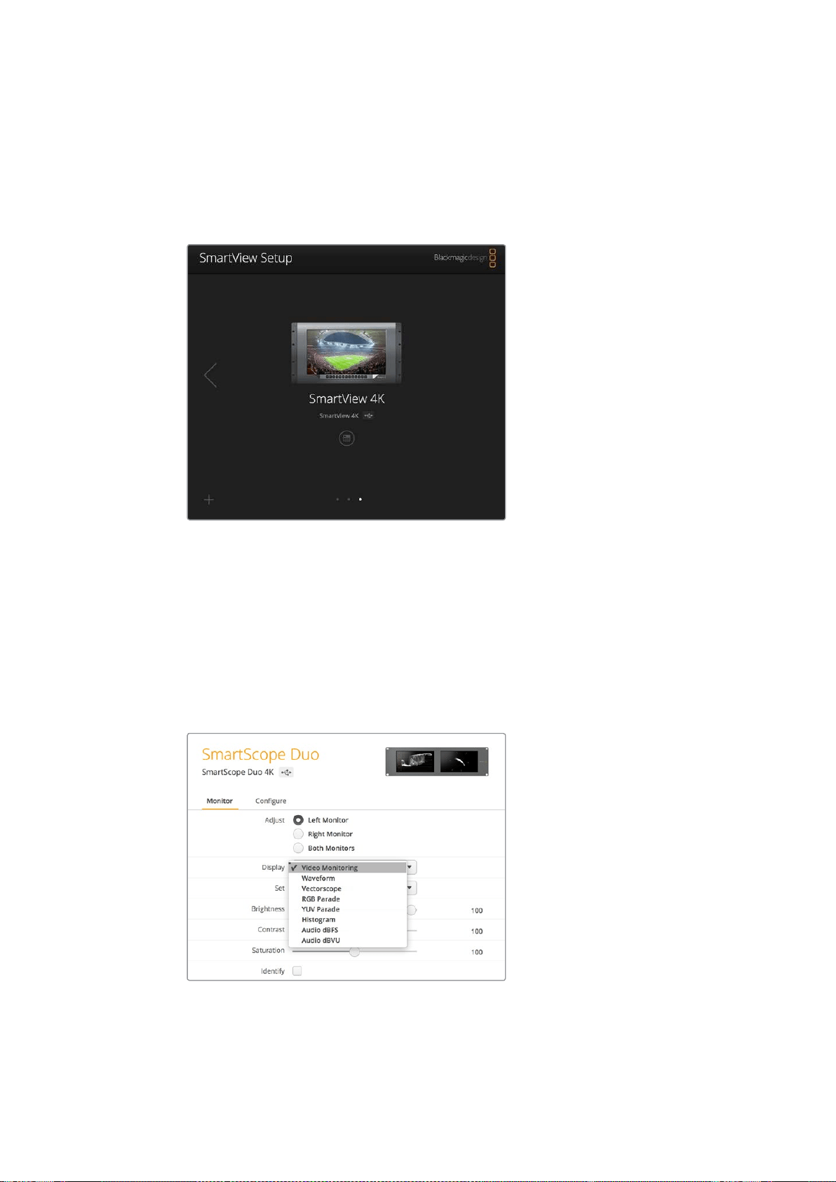
161Uso del programa SmartView Setup
Para cambiar las opciones, seleccione la unidad conectada y haga clic en el ícono de configuración
debajo del nombre. Esto permite acceder al panel de ajustes. Una vez realizados los cambios
necesarios, haga clic en el botón Save para guardarlos y volver a la ventana de inicio.
Consulte el apartado siguiente a fin de obtener información adicional sobre las opciones
disponibles para cada modelo. Consulte el apartado “Ajustes de red” para saber más sobre la
configuración de redes mediante el programa SmartView Setup.
El programa busca automáticamente las unidades conectadas
en forma local mediante un cable USB o a través de una red.
Compruebe que el dispositivo esté conectado antes de actualizarlo.
El ícono de la conexión USB aparece junto al nombre del monitor.
Ajustes del monitor
Para cambiar los ajustes del monitor, este debe estar conectado al equipo informático mediante
un cable USB o una red local. Seleccione la unidad mediante las flechas situadas en el margen
izquierdo y derecho de la ventana de inicio. A continuación, haga clic en el ícono de configuración
debajo del nombre del dispositivo. La pestaña de ajustes mostrará las opciones disponibles para
la unidad seleccionada.
Opciones disponibles en el modelo SmartScope
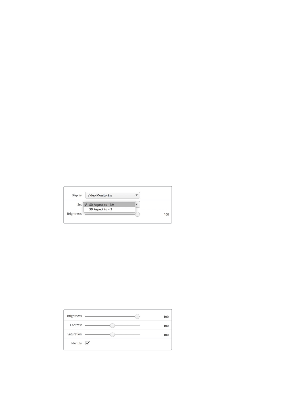
162Uso del programa SmartView Setup
Ajustar
En el caso de los modelos SmartScope y SmartView Duo, el panel Adjust permite seleccionar
el monitor que se desea ajustar. Al escoger la opción Both Monitors, los cambios en el brillo,
el contraste y la saturación afectarán a ambas pantallas.
Mostrar
En el caso del modelo SmartScope, el menú desplegable Display permite elegir la representación
gráfica que se muestra en la pantalla. Para ver la señal, seleccione la opción Video Monitoring.
Relación de aspecto
En el caso del modelo SmartScope, el menú desplegable Set permite determinar la relación de
aspecto para las imágenes en definición estándar. Asimismo, existen otros ajustes adicionales
según la opción elegida en el menú desplegable Display.
Monitorización: Al seleccionar la opción Video Monitoring, es posible escoger una
relación de aspecto de 4:3 o 16:9 para las imágenes que se muestran en la pantalla.
La opción 16:9 resulta adecuada para ver imágenes anamórficas en definición estándar
con formato de pantalla ancha. Por el contrario, elija la opción 4:3 para el formato habitual
en televisión.
Vectorscopio: Al seleccionar la opción Vectorscope, es posible elegir barras de color
al 75% o al 100% para la señal de ajuste.
Audio dBFS: Permite seleccionar el par de canales de audio que se desea monitorizar.
Audio dBVU: Permite seleccionar el par de canales de audio que se desea monitorizar.
Seleccione la opción SD Aspect to 16:9 para ver
imágenes anamórficas en definición estándar.
Brillo, contraste y saturación
Ajuste los controles Brightness, Contrast y Saturation según los valores deseados.
Identificación del monitor
Cuando la casilla Identify está marcada, la unidad seleccionada en el programa SmartView Setup
mostrará un borde blanco en la pantalla. Esta función permite identificar fácilmente el dispositivo
si hay varios conectados a una misma red.
Al emplear esta función junto con la opción Both Monitors, el borde blanco aparecerá en ambas
pantallas de los modelos SmartView Duo y SmartScope Duo 4K.
Deslice los controles para ajustar el brillo, el contraste y la saturación.
Marque la casilla Identify para identificar la unidad seleccionada.
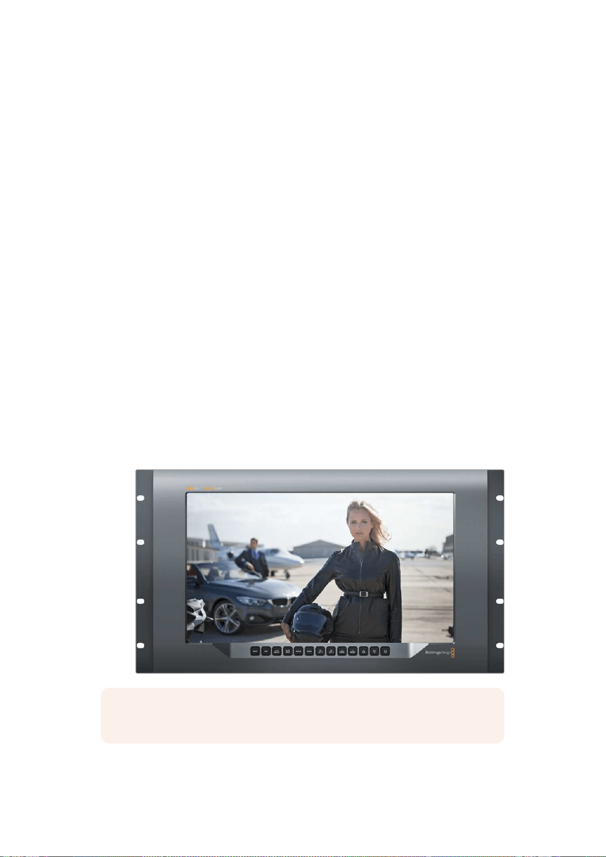
163SmartView 4K
SmartView 4K
Introducción
El modelo SmartView 4K es un monitor profesional UHD de 6U que incluye conectividad SDI 12G
y permite ver imágenes con una resolución original de 2160p60. Es compatible con una amplia
variedad de formatos y dispone de una pantalla brillante con un amplio ángulo de visión que ofrece
una imagen extraordinariamente nítida, a fin de facilitar el enfoque y la monitorización del color.
Diseñado tanto para estudios como exteriores, este modelo es muy sencillo de usar. Incluye
conectores laterales y puede colocarse en espacios pequeños, paredes o brazos articulados,
gracias a su compatibilidad con soportes tipo VESA. Cabe mencionar que es posible controlar
el dispositivo mediante el panel frontal o en forma remota, a través de una red Ethernet.
Las entradas SDI12G permiten alternar entre dos fuentes distintas, mientras que la conexión para
transceptores SFP brinda la posibilidad de utilizar módulos de fibra óptica. Por su parte, la salida
SDI12G facilita la transmisión de señales a otros equipos, y los dos conectores Ethernet hacen
posible el uso de redes informáticas para controlar el dispositivo en forma remota. Además, la salida
derivada proporciona un medio sencillo de conectar varias unidades en serie. Este modelo incluye
asimismo una conexión para luces piloto que resulta de gran utilidad durante producciones en
directo y un puerto USB para actualizar el sistema operativo interno.
El programa SmartView Setup permite aplicar tablas de conversión 3D (.cube) convencionales o
creadas en DaVinci Resolve. De esta forma, al conectar una cámara al monitor, es posible ver cómo
quedarían las imágenes una vez realizado el etalonaje. Por otra parte, los dos niveles del indicador
de enfoque brindan la oportunidad de lograr una nitidez extraordinaria. A su vez, el equipo puede
alimentarse mediante corriente alterna o continua, lo cual facilita el uso de baterías externas para
ofrecer una mayor portabilidad.
El modelo SmartView 4K es la solución ideal para supervisar contenidos audiovisuales en distintas
definiciones a una resolución máxima de 3840 x 2160.
NOTA: Al conectar una fuente de alimentación externa a la entrada para corriente continua,
compruebe que esta sea capaz de suministrar una potencia de 24 vatios a 12 voltios.
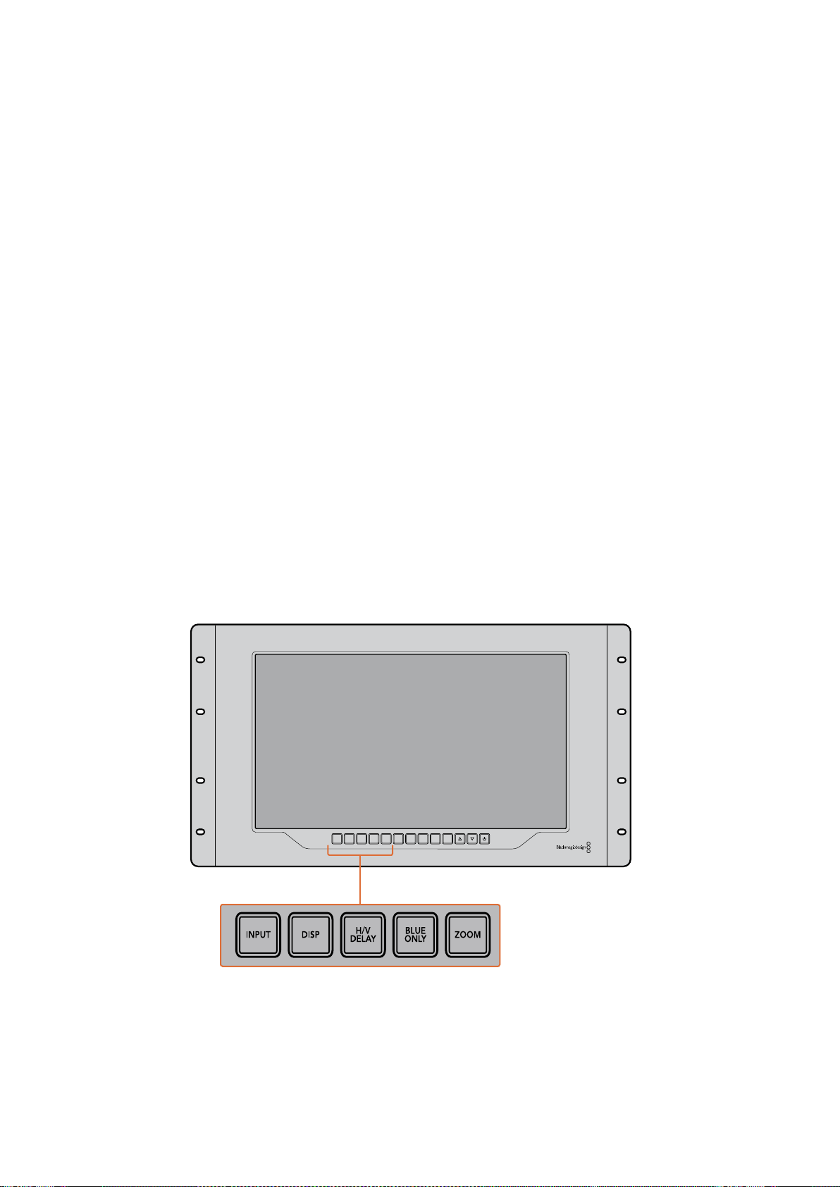
164SmartView 4K
Botones del panel de control
Los botones en la parte frontal del dispositivo permiten modificar diversos ajustes con rapidez.
Entrada
El botón INPUT permite alternar entre las fuentes conectadas a las dos entradas SDI12G del
dispositivo o al transceptor óptico SFP. Si no se detecta una señal, la pantalla mostrará una imagen
en negro. Al cambiar de una entrada a otra, se indica brevemente el formato de la señal en la
esquina superior izquierda del monitor.
Pantalla
El botón DISP permite aumentar o disminuir el brillo de la pantalla presionando las flechas
correspondientes. Oprima dicho botón nuevamente para salir.
Datos auxiliares
El botón H/V DELAY permite confirmar rápidamente la presencia de datos auxiliares integrados
en la señal SDI. Presiónelo una vez para ver la información contenida en el intervalo de supresión
horizontal. Oprímalo nuevamente para ver los datos en el intervalo de supresión vertical, tales como
subtítulos opcionales (CC).
Solo azul
El ruido en una señal digital se manifiesta principalmente en el canal azul. Para comprobarlo,
presione el botón BLUE ONLY. Este permite ver dicho canal representado como una imagen
en blanco y negro que también puede utilizarse para verificar el enfoque de la cámara.
Distancia focal
El botón ZOOM permite mejorar el enfoque de la cámara. Presiónelo para acercar la imagen
en la pantalla, a fin de poder comprobar si algún objeto determinado se encuentra fuera de foco.
Oprima este botón nuevamente para regresar al modo de visualización habitual.
INPUT DISP
H/V
DELAY
3D
LUT 1
BLUE
ONLY
ZOOM PEAK
3D
LUT 2
H
MARK
V
MARK
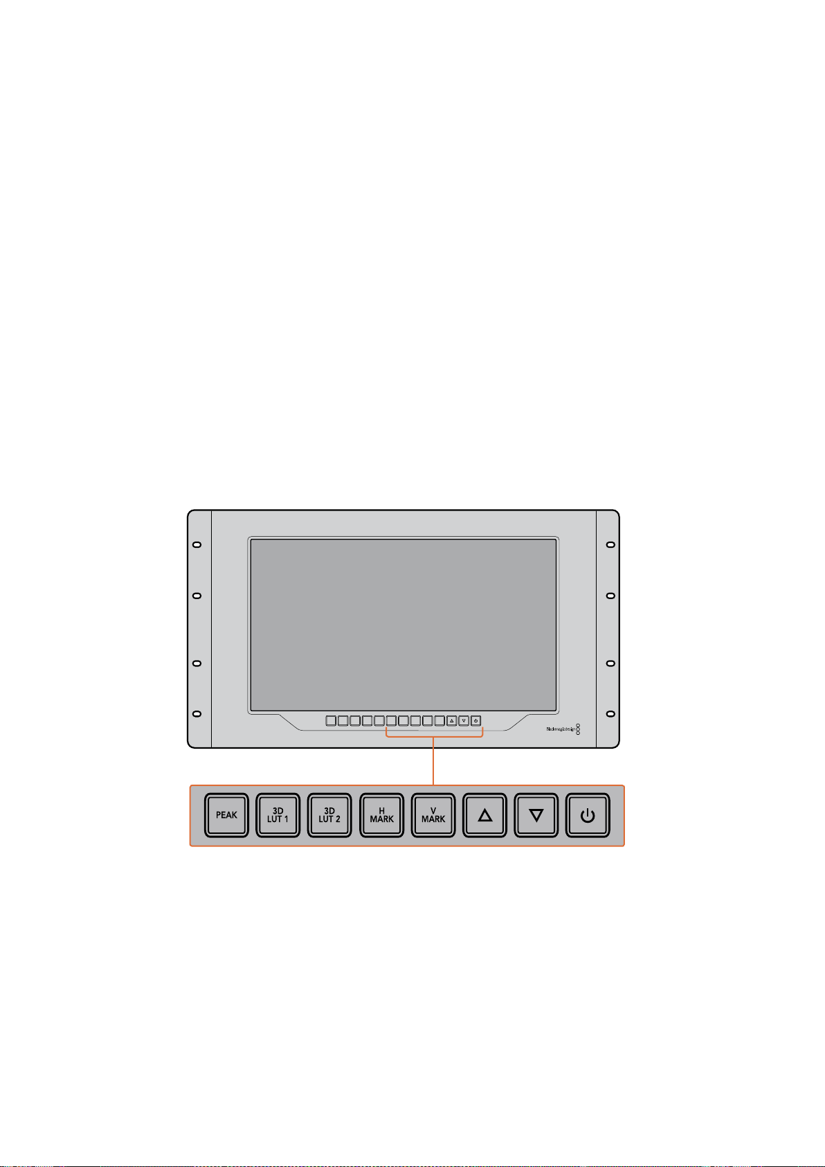
165SmartView 4K
Indicador de enfoque
El botón PEAK permite activar el indicador de enfoque, que muestra un borde verde brillante en
torno a los puntos más nítidos de la imagen. Al oprimirlo, también es posible alternar entre los dos
niveles disponibles. Cuando el color del borde es más intenso, la cámara está enfocada
correctamente.
LUT 3D
Los botones 3D LUT 1 y 3D LUT 2 permiten aplicar tablas de conversión convencionales (.cube) o
creadas en DaVinci Resolve. Presiónelos para activar o desactivar una tabla determinada. Consulte
el apartado “Aplicar LUT 3D con SmartView Setup” para obtener más información al respecto.
Guía vertical / horizontal
Los botones H MARK y V MARK permiten ver las guías de encuadre y cambiar su posición. Estas
líneas facilitan la composición de planos para mantener ciertos elementos gráficos o información
importante dentro del área visible de la pantalla. La imagen grabada puede ser levemente mayor
o menor a la superficie de la pantalla de un televisor. El área de seguridad corresponde a la parte
de la señal que siempre es visible, independientemente del monitor o televisor utilizado.
Presione el botón H MARK o V MARK para ver el margen horizontal o vertical, respectivamente.
Oprímalos una vez más para cambiar su posición. A continuación, utilice las flechas para
desplazarlo. Para confirmar, presione nuevamente el botón correspondiente. Oprímalo una vez
más para ocultar las guías.
Flechas
Las flechas permiten cambiar diferentes parámetros, tales como el brillo de la pantalla o la posición
de las guías.
Encendido
Presione el botón de encendido una vez para prender el dispositivo. Oprímalo nuevamente
para apagarlo.
INPUT DISP
H/V
DELAY
3D
LUT 1
BLUE
ONLY
ZOOM PEAK
3D
LUT 2
H
MARK
V
MARK

166SmartView 4K
Aplicar LUT 3D con SmartView Setup
El modelo SmartView 4K permite supervisar imágenes aplicando tablas de conversión
tridimensionales. Esto brinda la posibilidad de calibrar el dispositivo o apreciar cómo se vería el
producto final una vez realizado el etalonaje. A su vez, las tablas proporcionan una manera rápida
de probar distintas apariencias. Estas se aplican por medio del programa SmartView Setup, que
ofrece la oportunidad de emplear archivos con extensión .cube o versiones creadas en DaVinci
Resolve. Consulte el manual de DaVinci Resolve para obtener más información al respecto.
Para aplicar una tabla de conversión:
1 Ejecute el programa SmartView Setup.
2 Haga clic en el botón Load junto a la opción Load LUT 1. Se abrirá una ventana para
elegir el archivo que contiene la tabla. Una vez seleccionado, haga clic en el botón Open.
3 Para aplicar la tabla seleccionada, presione el botón 3D LUT 1 en el panel frontal del
dispositivo. Para desactivarla, oprima dicho botón nuevamente.
Repita el mismo procedimiento para aplicar una segunda tabla de conversión tridimensional
mediante la opción Load LUT 2.
El programa SmartView Setup permite aplicar tablas de conversión
tridimensionales a las imágenes visualizadas en el dispositivo.

167SmartScope Duo 4K
SmartScope Duo 4K
¿Qué es Blackmagic SmartScope?
Antes los instrumentos para medir los diferentes aspectos de una señal audiovisual en estudios de
televisión y posproducción eran extraordinariamente caros y solo permitían ver un aspecto de la
misma en una pantalla muy pequeña. Además, algunos de estos dispositivos son desagradables
y no lucen bien frente al cliente.
El modelo SmartScope Duo 4K ofrece la posibilidad de ver cualquier aspecto de la señal al instante
en dos monitores. Los ajustes realizados en la fuente mediante el programa SmartView Setup
pueden apreciarse inmediatamente en las pantallas del dispositivo. Asimismo, la señal recibida
puede transmitirse a cualquiera de ellas a través de la salida SDI derivada, lo cual permite ver las
imágenes en el monitor izquierdo y las representaciones gráficas correspondientes en el derecho.
Los diferentes indicadores disponibles se seleccionan mediante el programa SmartView Setup
desde el menú desplegable Display.
A continuación se brinda una descripción más detallada de las representaciones gráficas y la forma
en que facilitan la supervisión de las señales.
El programa SmartView Setup permite ver representaciones
gráficas diferentes en cada pantalla del dispositivo.
Imágenes
La opción Video Monitoring permite ver las imágenes correspondientes a la señal recibida.
Si su definición es estándar, es posible seleccionar una relación de aspecto de 4:3 o 16:9 desde
el menú desplegable Set. Cualquier variación del brillo, el contraste o la saturación se aprecia
inmediatamente en la pantalla. Cabe mencionar que estos ajustes solo afectan al monitor y no
a la imagen en sí misma. Por lo tanto, no se observarán cambios en las representaciones gráficas.

168SmartScope Duo 4K
Puede resultar útil emplear una de las pantallas para supervisar las imágenes y la otra para ver los
indicadores. A tales efectos, conecte un cable corto desde la salida SDI derivada del monitor 1
a la entrada correspondiente del monitor 2.
Las imágenes en definición estándar pueden verse con una relación
de aspecto de 4:3 o 16:9 eligiendo la opción correspondiente en el
menú Set. Seleccione SD Aspect to 16:9 para contenidos anamórficos.
La opción Video Monitoring permite observar la señal tal como se vería
normalmente en la pantalla de un monitor o televisor.
Forma de onda
La opción Waveform permite ver la onda de la señal codificada digitalmente, en forma similar
a un osciloscopio tradicional, a fin de ajustar el brillo de la imagen.
Los monitores de luminancia convencionales solo ofrecen la posibilidad de supervisar señales
analógicas compuestas en definición estándar. Sin embargo, el modelo SmartScope Duo 4K
también admite imágenes HD y UHD, facilitando de esta manera el ajuste del brillo en señales con
diversos formatos.
Seleccione la opción Waveform en el menú desplegable Display del programa SmartView Setup.
Compruebe que los valores para el color negro no caigan por debajo de 0%, y que aquellos
correspondientes al blanco no superen el 100%, a fin de garantizar que la luminancia se encuentre
dentro del rango permitido.
Esta representación gráfica muestra los valores del brillo en las distintas partes de la imagen.
Por ejemplo, si una parte del cielo está sobreexpuesta, se reflejará en la misma posición horizontal
en la gráfica.
La forma de onda será diferente según el material grabado. Si este es de alto contraste, es posible
que no se aprecien valores en los tonos grises intermedios. La siguiente ilustración muestra la
gráfica correspondiente a una imagen cuya exposición es pareja, con una zona oscura a la izquierda
y mayor brillo desde el centro hacia la derecha.

169SmartScope Duo 4K
Representación gráfica de la luminancia en la imagen
Seleccione la opción Waveform en el menú desplegable Display para
ver una representación gráfica de la luminancia en la señal.
Vectorscopio
Como su nombre lo indica, esta es una representación vectorial de los colores presentes en la
señal. Seleccione la opción 100% o 75% en el menú desplegable Set según la carta de ajuste
utilizada.
A pesar de que algunas personas piensan que es posible identificar valores cromáticos no
adecuados mediante el vectorscopio, esto no es así. Para ello, es necesario recurrir a la gráfica
de colores primarios. La razón por la cual el vectorscopio no resulta apropiado a tal fin es que se
necesitan tanto parámetros de crominancia como de luminancia. Por ejemplo, los colores cercanos
a las partes blancas o negras de la imagen tienen menos posibilidades de saturarse que aquellos
más intensos utilizados en los tonos intermedios. Dado que esta representación no indica los
valores de luminancia sino solo los matices cromáticos, no permite determinar si existen niveles
de color inadecuados.
El vectorscopio es una herramienta ideal para comprobar dichos niveles en señales analógicas
cuando es necesario ajustar la crominancia. Basta con reproducir el segmento de la secuencia que
contiene las barras de color y luego ajustar el matiz y la crominancia según las casillas en la gráfica.
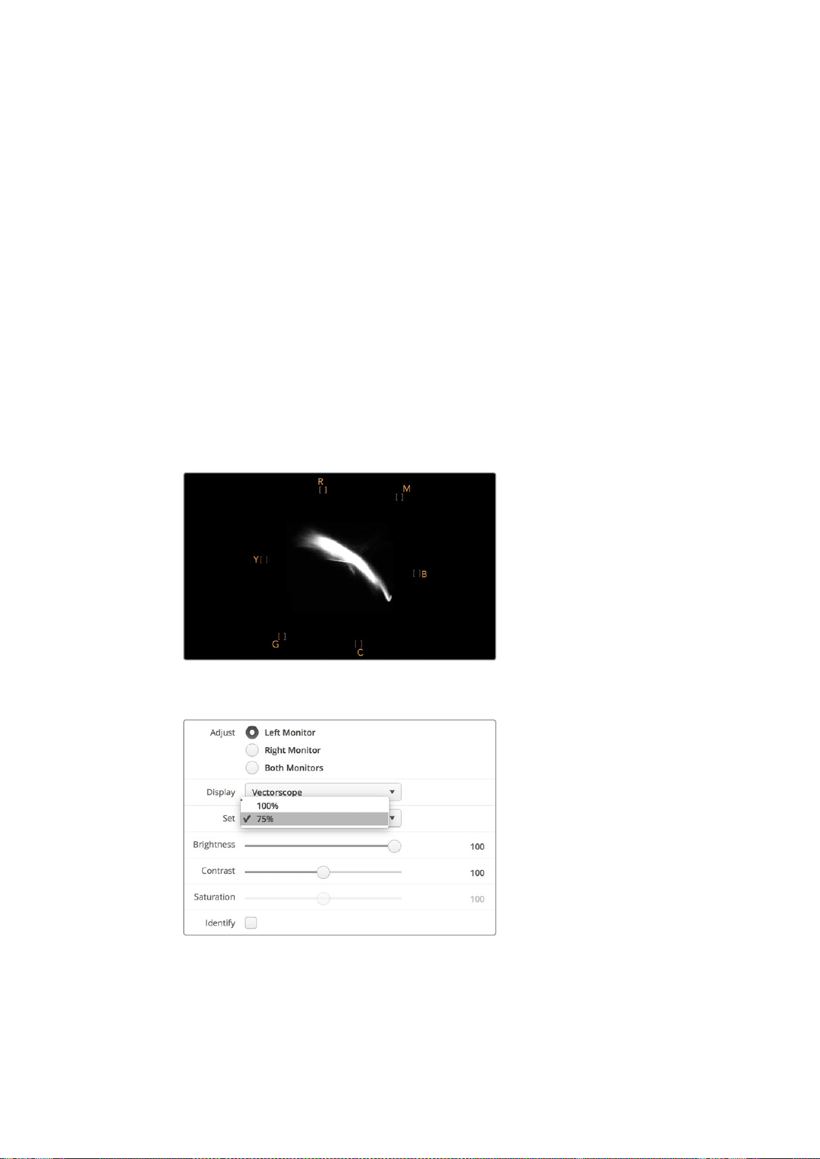
170SmartScope Duo 4K
Asimismo, este indicador resulta óptimo al llevar a cabo el etalonaje, ya que permite determinar si el
balance de blancos es adecuado. En caso de que exista cierto matiz cromático, la gráfica se alejará
del centro y posiblemente aparezcan dos puntos centrales. En general, el intervalo de supresión en
la señal generará un punto en el centro del vectorscopio, dado que corresponde a una parte de la
imagen completamente oscura. Este constituye un punto de referencia útil que facilita el
reconocimiento de las áreas sin información cromática.
Si la imagen presenta algún matiz, la representación gráfica se alejará de los puntos de referencia
y del centro. La magnitud del cambio es proporcional al grado del matiz y se puede apreciar tanto
en las zonas claras como oscuras de la imagen. Por esta razón, el vectorscopio resulta de gran
ayuda para eliminar cualquier tonalidad y lograr un balance de blancos adecuado.
Por otra parte, el vectorscopio permite incrementar la intensidad de los colores sin agregar matices
no deseados a las partes más brillantes y oscuras de la imagen. Aunque tanto la gráfica de colores
primarios como el vectorscopio permiten determinar el balance de blancos, este último brinda la
oportunidad de identificar posibles problemas con mayor facilidad.
Al corregir los tonos de piel, especialmente en los rostros, los valores correspondientes a la
saturación de los colores cálidos deben reflejarse a lo largo de una línea que apunta
aproximadamente a la hora 10. Esta línea, conocida como “flesh tone line”, se basa en el color de la
sangre debajo de la superficie de la piel. Por consiguiente, este método puede aplicarse a cualquier
tipo de pigmentación y es la mejor manera de asegurarse de que los tonos de piel luzcan naturales.
Imagen del vectorscopio que muestra la
representación gráfica de los tonos de piel
Seleccione la opción 100% o 75% en el menú
desplegable Set del programa SmartView Setup.
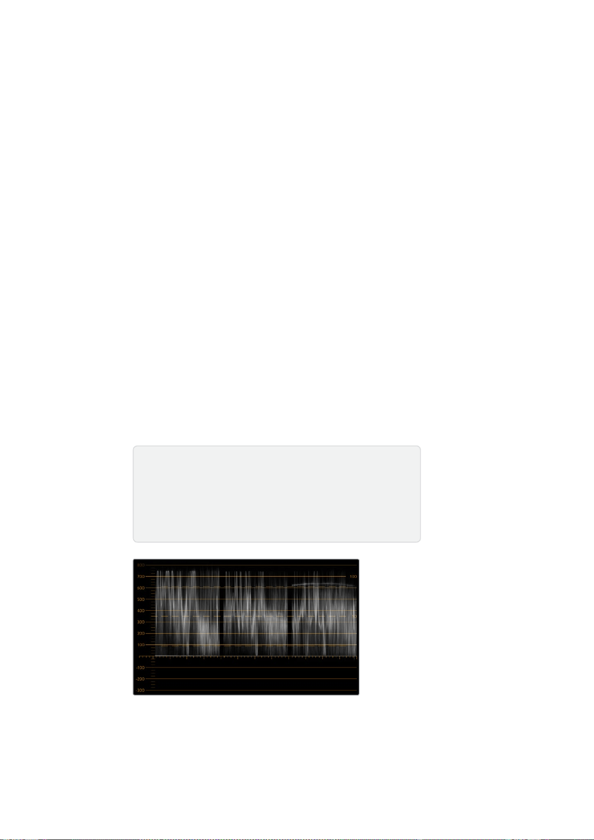
171SmartScope Duo 4K
Luminancia y crominancia
Las gráficas RGB y YUV son ideales para establecer niveles cromáticos adecuados.
Al realizar el etalonaje, seleccione la opción RGB Parade en el menú desplegable Display del
programa SmartView Setup. Esta permite ver una representación de los canales rojo, verde y azul
que hace posible determinar sus niveles, facilitando de este modo la comprobación del balance de
color en las zonas más claras y oscuras de la imagen, así como en los tonos intermedios. A su vez,
esto brinda la oportunidad de identificar problemas comunes a los tres canales, simplificando de
esta forma la eliminación de matices no deseados.
Al etalonar las imágenes, es importante aprovechar al máximo el rango cromático sin excederse de
los límites permitidos. Si desea aumentar los niveles, compruebe que no superen el límite superior
de la gráfica. Aunque algunos dispositivos no permiten establecer valores fuera de dicho rango,
otros no cuentan con esta función. El modelo SmartScope Duo 4K ofrece la posibilidad de
determinar si los parámetros son adecuados.
Lo mismo sucede con los valores para el blanco y el negro. Algunos sistemas de etalonaje permiten
disminuir el nivel del negro por debajo de 0%. Si observa un nivel de negro inadecuado, ajuste la
ganancia, pero también compruebe la retícula para verificar que no se hayan alterado los valores
de las zonas más claras de la imagen.
Para ver la gráfica de luminancia, seleccione la opción YUV Parade en el menú desplegable
Display. Esta es de suma utilidad, puesto que el brillo está separado del color y, por otra parte,
es el formato que se emplea en la teledifusión de material audiovisual. La primera forma de onda
situada a la izquierda brinda información sobre la luminancia; la segunda y la tercera, sobre la
crominancia. Esta gráfica es ideal para calibrar una señal empleando barras de color como carta
de ajuste, de manera que los colores se representen con precisión, para que el contenido
transmitido pueda verse en cualquier televisor.
Cabe destacar que es necesario realizar ajustes cromáticos constantemente, a fin de lograr
la mejor calidad de imagen, sin excederse de los niveles permitidos.
Gráfica RGB
Terminología
Negro – Intensidad del color negro en la señal.
Tonos intermedios – Intensidad de los tonos grisáceos en la señal.
Blanco – Intensidad del color blanco en la señal.
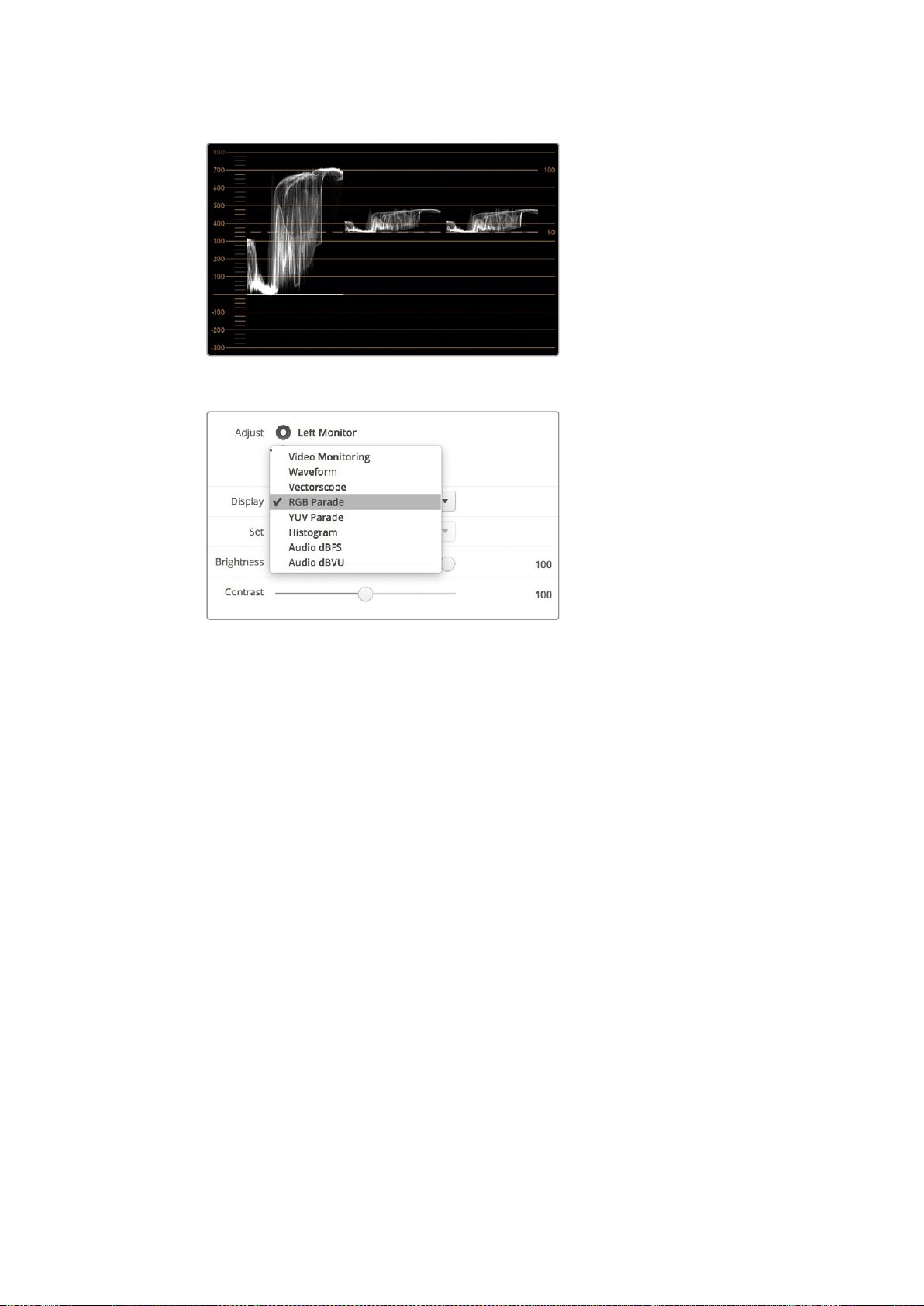
172SmartScope Duo 4K
Gráfica YUV
Las opciones RGB Parade y YUV Parade
están disponibles en el menú Display.
Histograma
Este indicador es el más utilizado por los diseñadores gráficos y operadores de cámara. Muestra la
distribución del blanco y el negro, y permite comprobar qué tan cerca se está de perder información
en la imagen. Asimismo, permite ver el efecto causado al modificar los tonos intermedios de
la imagen.
Las zonas más oscuras corresponden a la izquierda de la gráfica, y las más claras, a la derecha.
Generalmente, la señal debe permanecer dentro del rango 0–100%. Fuera de este, se perderá
información en la imagen. Es preciso evitar que esto suceda durante el rodaje, ya que los detalles
de las zonas más claras y oscuras deben conservarse para poder realizar ajustes cromáticos
posteriormente en un entorno controlado. Durante la filmación, es necesario mantener la señal
dentro del rango mencionado, a fin de tener mayor flexibilidad a la hora de ajustar los colores sin
que el blanco o el negro luzcan apagados.
Al etalonar material audiovisual, a veces se permite que los valores se sitúen fuera de dicho rango
para lograr un cierto efecto, en cuyo caso el histograma mostrará el resultado del cambio, indicando
además cuánta información se pierde. Asimismo, es posible ajustar los tonos intermedios para crear
una apariencia similar conservando más detalles.
De hecho, es posible recurrir al histograma para comprobar todos los valores de la imagen, sino
solo aquellos correspondientes al blanco y al negro. El histograma no brinda información cromática,
por lo cual puede indicar niveles normales cuando en realidad los valores de la imagen son
inadecuados. Como se mencionó anteriormente, la gráfica de componentes cromáticos (o RGB) es
la herramienta ideal para comprobar dichos niveles, ya que indica tanto la crominancia como la
luminancia de la señal.
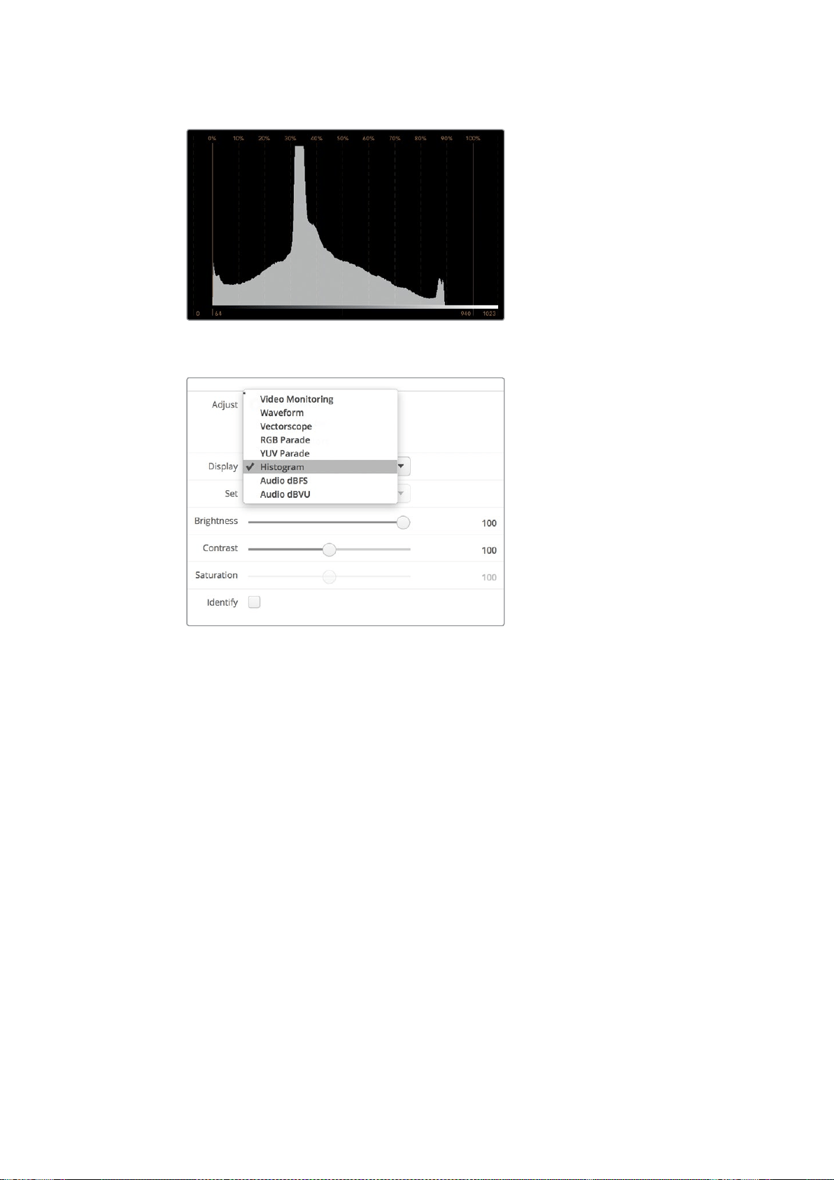
173SmartScope Duo 4K
El histograma muestra las zonas más claras y oscuras de la imagen.
Seleccione la opción Histogram en el menú
desplegable Display del programa SmartView Setup.
Medición del audio
Este modo de visualización indica la intensidad del audio integrado en la señal SDI. Permite ver
información sobre un máximo de 16 canales en decibelios a escala completa o en formato VU.
El vúmetro indica el nivel promedio de la señal y es más común en dispositivos de mayor
antigüedad. Está calibrado según la recomendación de la SMPTE, con un volumen predeterminado
de -20dBFS para un tono de 1kHz (señal de prueba).
Esta unidad de medida permite medir la señal de audio digital en general y es común en equipos
más modernos.
El indicador derecho brinda la posibilidad de monitorizar dos canales de audio seleccionándolos
en el menú desplegable Set. La información se presenta en un gráfico que permite identificar
problemas en el balance del audio y determinar si la señal está desfasada, o si una determinada
pista es monoaural o estéreo. El audio monoaural debería aparecer representado como una línea
vertical. Una horizontal indica que el audio está desfasado, y la señal podría perderse al ser recibida
por otro equipo. Este es uno de los problemas más comunes en grandes instalaciones donde los
cables pueden estar mal conectados.

174Conexión a redes
Al monitorizar señales en estéreo, la línea a la derecha del indicador se despliega a modo de
abanico para representar las diferencias entre los canales izquierdo y derecho. La forma que
dicha línea adoptará será más circular si la pista de audio es más estereofónica. En caso contrario,
la gráfica tenderá a concentrarse alrededor del eje vertical.
Generalmente los diálogos se ven como una línea vertical, mientras que en el caso de música en
estéreo, la gráfica se extenderá. Esto se debe a que el audio monoaural (L+R) se muestra sobre
el eje vertical, mientras que el sonido en estéreo (L-R) se representa sobre el eje horizontal para
indicar la diferencia entre ambos canales.
El vúmetro muestra los picos en la señal y el balance de audio.
En el menú Set, seleccione el par de canales que desea monitorizar.
Conexión a redes
Al conectar un monitor SmartView o SmartScope a una red, es posible realizar ajustes en varias
unidades remotamente.
Aunque no es necesario configurar los dispositivos para ver una señal en la pantalla, es preciso
verificar los ajustes de la red en forma previa. Esto solo es posible mediante una conexión USB
directa al equipo informático.
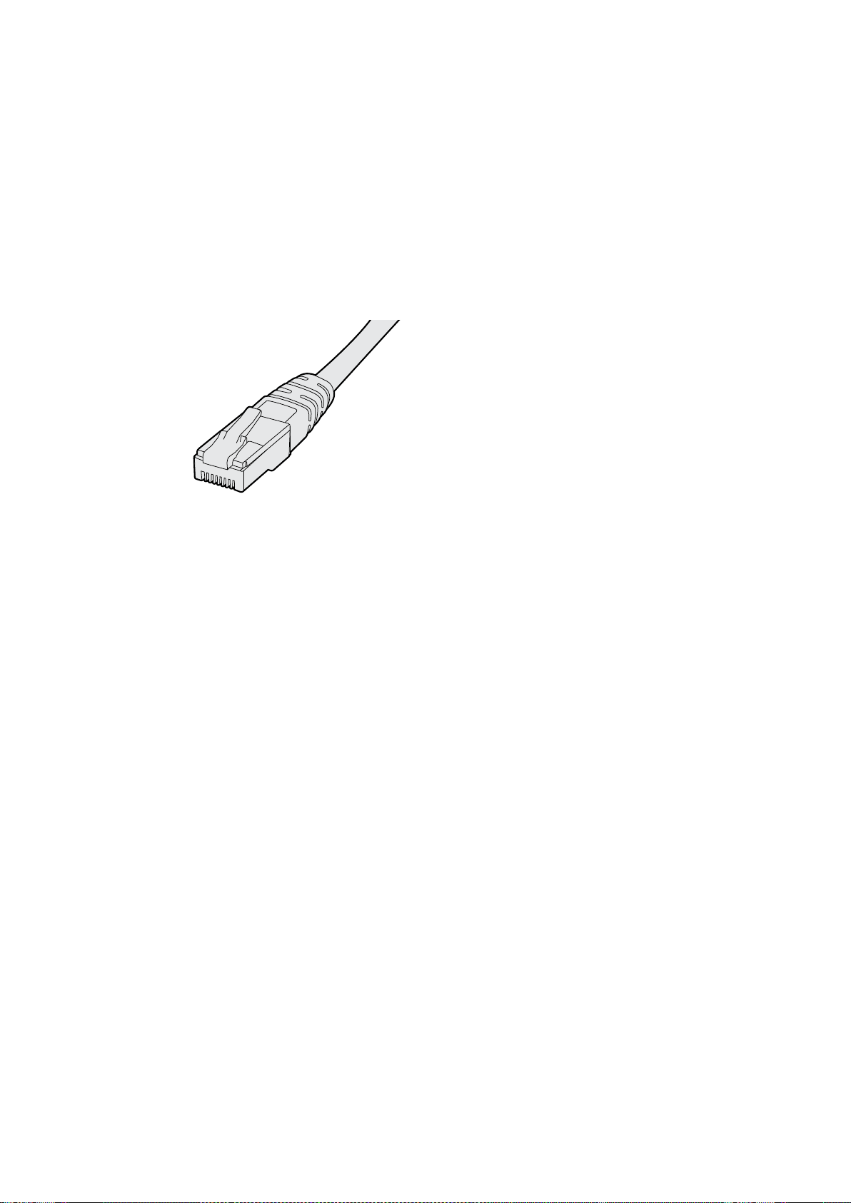
175Conexión a redes
Conexión Ethernet directa
El monitor puede configurarse remotamente mediante una conexión Ethernet directa al equipo
informático. No es necesario utilizar un conmutador de red, lo cual permite instalar el dispositivo
rápidamente. Cabe destacar además que es posible conectar varias unidades en serie mediante
el puerto Ethernet de cada una. Nótese que todas ellas deberán contar con suministro eléctrico.
En caso de no disponer de una red, o para utilizar varias unidades sin direcciones IP, conéctelas
directamente al puerto Ethernet del equipo informático. Esto ofrece una manera rápida de conectar
unidades SmartView y SmartScope, dado que no es necesario emplear cables adicionales ni un
conmutador de red.
Conector Ethernet
Conmutador de red
Para utilizar varias unidades en una misma red, es suficiente con conectar un monitor SmartView
o SmartScope al conmutador de red. El resto puede conectarse en serie mediante el puerto
Ethernet de cada unidad, a fin de ocupar solo una conexión en el conmutador. De esta forma,
es posible prescindir del uso de cables adicionales. Nótese que todas las unidades deberán
contar con suministro eléctrico.
Un conmutador facilita la configuración de las unidades desde cualquier equipo informático
conectado a la red. Asimismo, si esta incluye un punto de acceso inalámbrico, es posible lograr
este cometido desde cualquier equipo Mac o Windows.
Siga los pasos descritos a continuación para conectar un monitor SmartView o SmartScope
a una red IP local.
1 Conecte la fuente de alimentación de la unidad y enciéndala.
2 Conecte la unidad a un conmutador de red o directamente a un equipo informático
mediante un cable RJ-45.
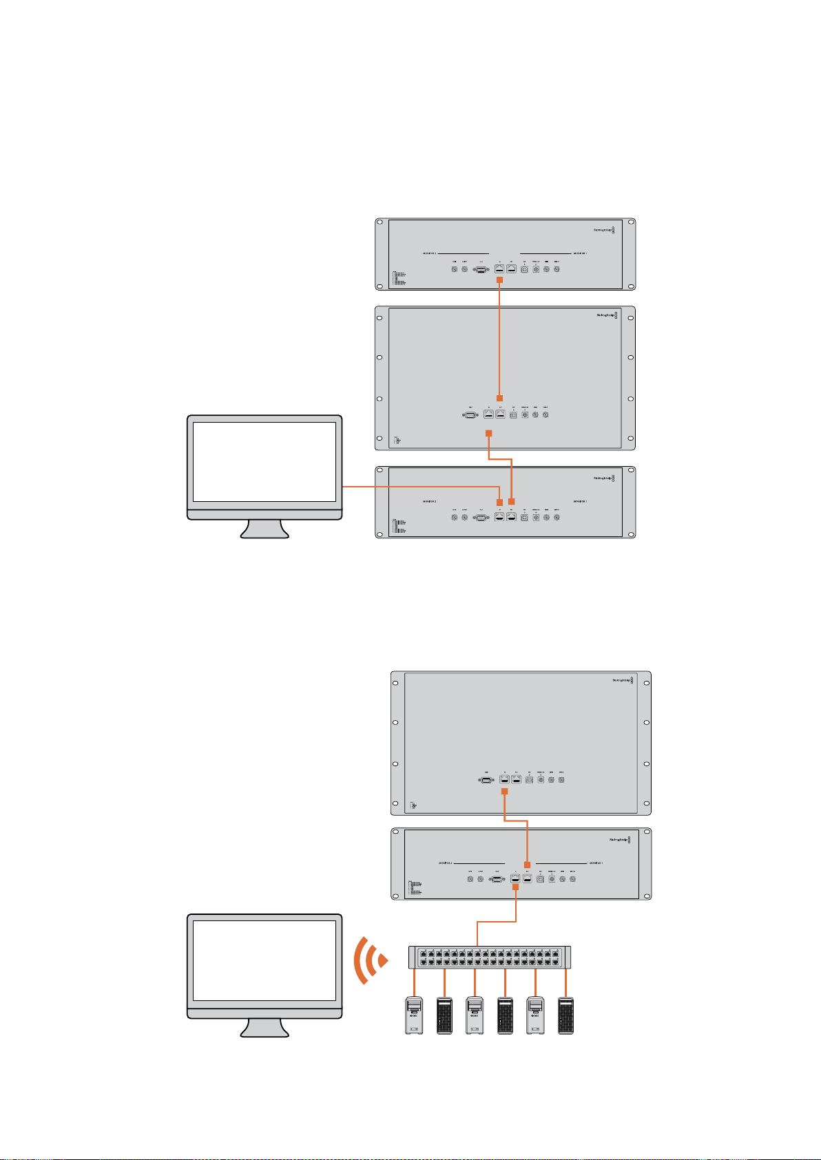
176Conexión a redes
Diagrama de conexión
Es posible conectar el puerto Ethernet de una unidad directamente al equipo informático sin un
conmutador de red. Las unidades restantes pueden conectarse en serie, lo cual permite prescindir
del uso de cables adicionales. Nótese que todas ellas deberán contar con suministro eléctrico.
Diagrama de conexión con un conmutador de red
Para utilizar varias unidades en una misma red, es suficiente con conectar solo una de ellas al
conmutador. Las restantes pueden conectarse en serie, lo cual permite prescindir del uso de cables
adicionales. Nótese que todas ellas deberán contar con suministro eléctrico.
SmartScope 4KDuo
SmartScope 4KDuo
Conmutador
Ethernet
Clientes

177Ajustes de red
Ajustes de red
Configuración de la red
Nombre del dispositivo
Es recomendable cambiar el nombre de cada monitor a fin de facilitar la identificación de las
unidades en la red.
Para ello, compruebe que el monitor esté conectado mediante un puerto USB o Ethernet. Ejecute el
programa SmartView Setup y haga clic en el ícono de configuración debajo del nombre del monitor.
En la pestaña Configure, haga clic sobre el nombre del monitor en el panel Details para cambiarlo.
Si el nombre no es válido, aparecerá un ícono de advertencia. De lo contrario, verá un visto verde
junto al mismo. Presione la tecla de retorno en el equipo informático para confirmar el cambio.
Configuración de la red
Para cambiar la configuración de red, el monitor debe estar conectado al equipo informático.
Cabe destacar que no es posible llevar a cabo este procedimiento mediante una conexión Ethernet.
De forma predeterminada, los dispositivos SmartView y SmartScope obtienen una dirección IP
automáticamente a través de la red, por medio del protocolo DHCP.
Si no cuenta con este protocolo, active la función Compartir Internet en macOS o Conexión
compartida a Internet (ICS) en Windows 8.1 o Windows 10 para asignar direcciones DHCP a las
unidades conectadas De este modo, no será necesario asignar una dirección IP fija a cada una
de ellas. Dicha función permite asignar direcciones IP incluso si el equipo informático no está
conectado a Internet. Consulte la documentación relativa a los sistemas operativos mencionados
para obtener más información al respecto.
Si no es posible emplear un protocolo DHCP para la configuración, utilice direcciones IP fijas.
Solicite una al administrador del sistema para evitar conflictos en la red. Cabe señalar que es
preciso indicar una dirección IP única para cada SmartView y SmartScope, así como una máscara
de subred común. No es necesario cambiar los valores del campo Gateway, a menos que se
proponga conectar las unidades a una puerta de enlace.
Si no se detecta ningún dispositivo en la red, es posible que las unidades no hayan recibido una
dirección IP mediante el protocolo DHCP, en cuyo caso será necesario configurar los ajustes
correspondientes en cada una de ellas.
1 Conecte el monitor al equipo informático mediante un cable USB y ejecute el programa
SmartView Setup.
2 La ventana principal del programa mostrará el dispositivo conectado y el ícono de la
conexión USB junto a su nombre.
3 Cambie la configuración de la red.
4 Repita este procedimiento para las restantes unidades que no hayan recibido una
dirección IP mediante el protocolo DHCP.
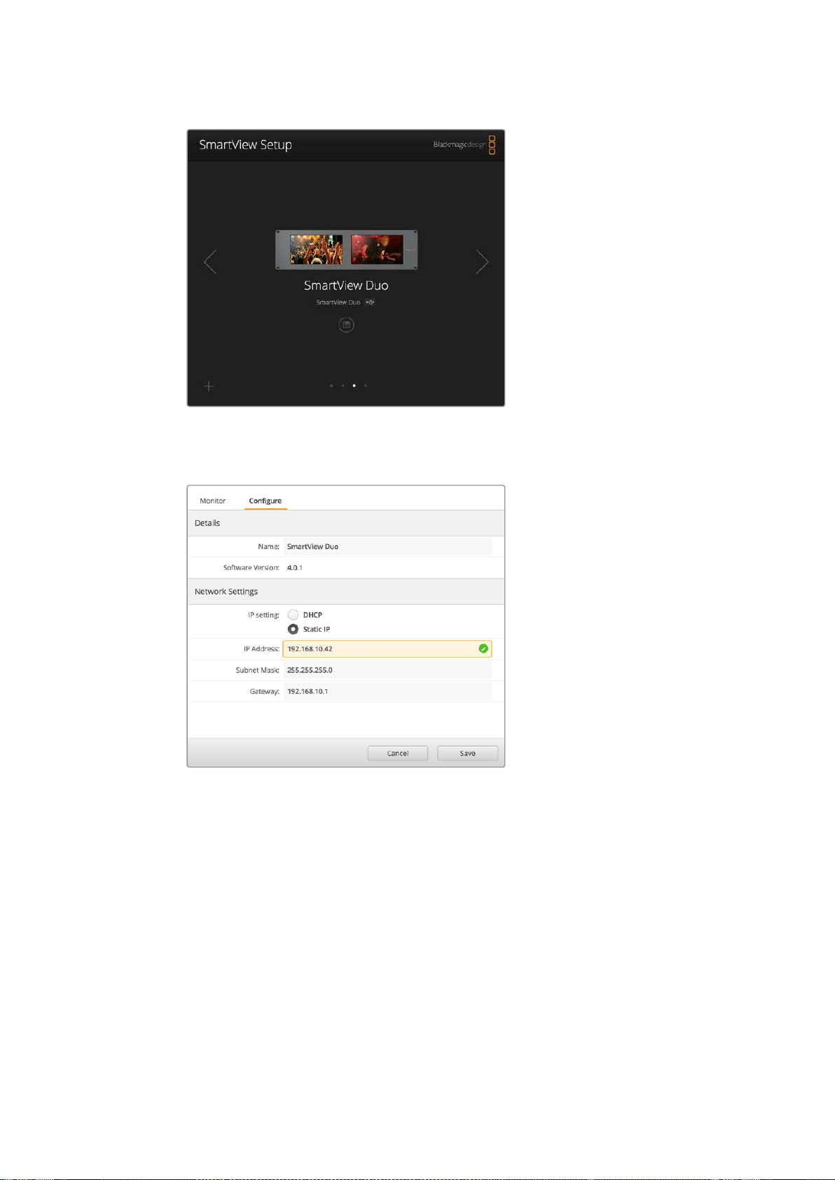
178Ajustes de red
El ícono junto al nombre del dispositivo indica que está
conectado al equipo informático a través del puerto USB.
Esto es necesario para poder cambiar la configuración de red.
Al configurar la red, es posible utilizar el protocolo
DHCP o direcciones IP fijas. Nótese que los ajustes
solo se pueden modificar a través de la conexión USB.
Agregar monitores a la red
Si conoce la dirección IP del monitor, es posible agregarlo a la red manualmente en caso de
que no aparezca en la ventana principal del programa SmartView Setup. Para ello, siga los pasos
descritos a continuación.
1 Compruebe que el monitor esté conectado mediante el puerto Ethernet. Haga clic en
el símbolo + situado en la esquina inferior izquierda de la interfaz para abrir la ventana
que permite añadir unidades.
2 Escriba la dirección IP del monitor y haga clic en el botón Add.
3 El programa verificará la presencia del monitor y lo agregará a la lista de unidades
conectadas. Haga clic sobre la flecha derecha para ver el monitor agregado.
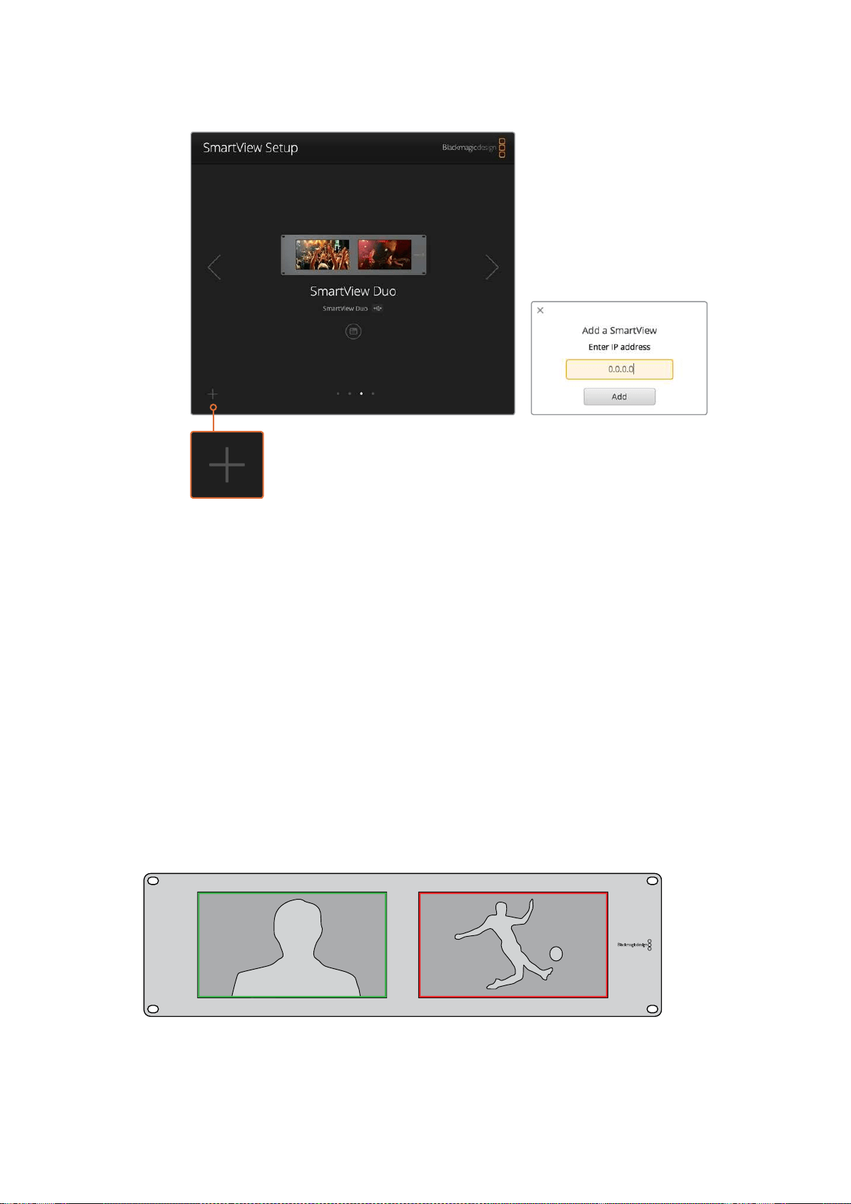
179Sistemas de señalización
Es posible agregar un monitor a la lista de unidades conectadas
haciendo clic en el símbolo + para introducir su dirección IP.
Sistemas de señalización
Conexión
No es necesario conectar la salida TALLY de los monitores ni leer este apartado si no pretende
utilizar esta función.
Cada dispositivo indica el estado de la señal al aire mediante un borde rojo, verde o azul alrededor
de la pantalla.
La conexión D de nueve pines admite señales provenientes de mezcladores y sistemas de
automatización. Consulte el diagrama ilustrado a continuación para obtener más información
al respecto.
El diagrama de conexión está impreso en la parte posterior de la unidad y describe cada uno de
los contactos que permiten utilizar el sistema de señalización.
Modelo SmartView Duo con bordes indicadores alrededor de cada pantalla

180Mejora del ángulo de visión
Mejora del ángulo de visión
Cuando el monitor se instala en la parte superior de un bastidor, es posible invertir la pantalla para
mejorar el ángulo de visión. En este caso, las imágenes se ajustarán automáticamente según la
orientación del dispositivo. Es necesario contar con un destornillador Pozidriv 02 para desmontar
y volver a colocar la parte frontal de la unidad. Este es un procedimiento sumamente sencillo que
no requiere la apertura de la parte trasera.
A continuación se describe la forma de invertir la unidad manteniendo a su vez el logotipo de
Blackmagic en la posición correcta. Nótese que es necesario contar con un destornillador
Pozidriv 02.
1 Quite los tornillos situados en la parte superior, inferior, izquierda y derecha de la testera.
Los modelos SmartView Duo y SmartScope Duo 4K incluyen 10 tornillos, y la versión
SmartView HD tiene 18.
2 Separe la testera de la parte trasera de la unidad, como se ilustra en la figura.
3 Gire la parte trasera de la unidad.
4 Instale nuevamente la testera.
5 Coloque los tornillos nuevamente y apriételos.
El dispositivo está listo para montarse en la parte superior de un bastidor. Una vez instalado,
continuará mostrando el ángulo de visión más adecuado, ya que no dispone de mandos o controles
externos que puedan desajustarse accidentalmente.
SmartView Duo y SmartScope Duo 4K
Conexiones
Pin Función
1 Monitor 1 rojo
2 Monitor 1 verde
3 Monitor 1 azul
4 Tierra
5 Tierra
6 Tierra
7 Monitor 2 rojo
8 Monitor 2 verde
9 Monitor 2 azul
SmartView HD y SmartView 4K
Conexiones
Pin Función
1 Red
2 Green
3 Blue
4 Tierra
5 4 3 2 1
9 8 7 6
Puerto D9


182Información para desarrolladores
Información para desarrolladores
Desarrollo de aplicaciones personalizadas con productos de Blackmagic Design
El protocolo de Ethernet desarrollado por Blackmagic permite controlar remotamente los
dispositivos SmartView y SmartScope mediante aplicaciones informáticas personalizadas.
Cabe destacar que se trata de un protocolo basado en texto.
Cómo obtener el protocolo de Ethernet
El protocolo es gratis. Puede descargarse desde la página de soporte técnico de Blackmagic
Design y sus funciones principales se describen en este manual.
Lista de desarrolladores de Blackmagic Design
Esta lista de distribución ha sido creada para ayudar a responder dudas técnicas relativas
a las diversas tecnologías empleadas por Blackmagic Design. Constituye un foro donde los
desarrolladores pueden discutir diferentes ideas con otros colegas y resolver problemas.
Cualquier persona suscrita puede intervenir en las distintas discusiones, así como los ingenieros
de Blackmagic Design cuando resulte apropiado. Para suscribirse, visite la siguiente página:
http://lists.blackmagicdesign.com/mailman/listinfo/bmd-developer
En algunos casos, solicitamos que se proporcione una breve descripción de la aplicación si el tipo
de software desarrollado no resulta evidente a partir del nombre de dominio. Solo lo hacemos para
evitar mensajes no deseados o preguntas de usuarios finales referidas a otras cuestiones, o que la
lista se vea afectada por un virus. Conviene subrayar que es una plataforma solo para
desarrolladores.
Cómo obtener asistencia
Por otras cuestiones relativas al desarrollo de aplicaciones, o si desea realizar preguntas fuera de la
lista, puede escribirnos a la siguiente dirección: de[email protected]
Formato 2K de Blackmagic – Información general
Los productos de Blackmagic Design permiten procesar señales SDI 3G, las cuales brindan la
posibilidad de transmitir datos al doble de velocidad que una señal en alta definición. Pensamos que
sería una buena idea que también fueran compatibles con imágenes en resolución 2K, a fin de
simplificar las dinámicas de trabajo en la industria cinematográfica. Gracias a la popularidad de los
sistemas de edición de Blackmagic Design, ahora miles de personas pueden sacar provecho de las
prestaciones que estos ofrecen.

183Información para desarrolladores
A continuación se proporciona toda la información necesaria para desarrollar equipos compatibles
con señales SDI en resolución 2K. Dado que todos nuestros productos pueden actualizarse, también
podemos ofrecer compatibilidad con otros formatos que la industria cinematográfica adopte en el futuro.
Estructura de cuadros
Transmisión a 23.98, 24 o 25 cuadros por segundo en formato PSF.
Imagen activa: 2048 pixeles x 1556 líneas.
Total de líneas por cuadro: 1650
Palabras activas por línea: 1535. Una palabra consta de una muestra de 10 bits para cada
uno de los cuatro flujos de datos, es decir, 40 bits en total. Consulte la tabla que figura en
la siguiente página.
Total de líneas activas: 1556
Total de palabras por línea: 1875 para 23.98/24Hz, y 1800 para 25Hz.
Campos por cuadro: 2 de 825 líneas cada uno.
Líneas activas: 16-793 (campo 1) y 841-1618 (campo 2).
Estructura de transporte
Basada en distribución de señales SMPTE 372M mediante dos enlaces y compatibilidad con
el estándar SMPTE 425M-B para transmitir señales SMPTE 372M mediante un enlace 3Gb/s.
Señales de referencia, número de línea e inserción CRC, según se describió anteriormente.
Durante una señal activa, los datos de 10bits relativos a los colores rojo, verde y azul se
envían en la siguiente secuencia:
Los datos auxiliares opcionales se insertan en ambas interfaces virtuales.
Actualmente, solo se incluye información relativa al audio. Según la norma SMPTE S299M,
los paquetes de audio se transmiten mediante el flujo 2, mientras que los paquetes de
control se envían a través del flujo 1.
Flujo de datos 1: Green_1, Green_2, Green_3, Green_5... Green_2047
Flujo de datos 2: Blue_1, Blue_2, Green_4, Blue_5... Green_2048
Flujo de datos 3: Red_1, Blue_3, Blue_4, Red_5... Blue_2048
Flujo de datos 4: Red_2, Red_3, Red_4, Red_6... Red_2048
Formato 2K de Blackmagic –
Referenciadetemporizaciónvertical
El siguiente diagrama brinda información sobre la temporización vertical con los números de línea y
los bits relativos al campo, el intervalo vertical y el intervalo horizontal para los códigos de la señal
de referencia.
Campo 1 Activo
F 1 0 0 0 0 0 0 0 0 0 0 0
V 1 1 1 1 1 1 0 0 0 0 1 1
LÍNEA 1650 1 2 ... 14 15 16 ... 792 793 ... 825
Campo 2 Activo
F 0 1 1 1 1 1 1 1 1 1 1 1
V 1 1 1 1 1 1 0 0 0 0 1 1
LÍNEA 825 826 827 ... 839 840 841 ... 1617 1618 ... 1650
184Información para desarrolladores
Formato 2K de Blackmagic – Transmisión de datos
El siguiente diagrama indica los formatos de los flujos de datos en torno al intervalo de la línea
horizontal para datos auxiliares opcionales. Nótese que cada pixel activo ocupa tres muestras.
Data Stream 1
G2041
G2042
G2043
G2045
G2046
G2047
EAV(3FFh)
EAV(000h)
EAV(000h)
EAV(XYZh)
LN0
LN1
CRC0
CRC1
ANC/Audio Data
SAV(3FFh)
SAV(000h)
SAV(000h)
SAV(XYZh)
G1
G2
G3
G5
Data Stream 2
B2041
B2042
G2044
B2045
B2046
G2048
EAV(3FFh)
EAV(000h)
EAV(000h)
EAV(XYZh)
LN0
LN1
CRC0
CRC1
ANC/Audio Data
SAV(3FFh)
SAV(000h)
SAV(000h)
SAV(XYZh)
B1
B2
G4
B5
Data Stream 3
R2041
B2043
B2044
R2045
B2047
B2048
EAV(3FFh)
EAV(000h)
EAV(000h)
EAV(XYZh)
LN0
LN1
CRC0
CRC1
040
…
040
SAV(3FFh)
SAV(000h)
SAV(000h)
SAV(XYZh)
R1
B3
B4
R5
Data Stream 4
R2042
R2043
R2044
R2046
R2047
R2048
EAV(3FFh)
EAV(000h)
EAV(000h)
EAV(XYZh)
LN0
LN1
CRC0
CRC1
200
…
200
SAV(3FFh)
SAV(000h)
SAV(000h)
SAV(XYZh)
R2
R3
R4
R6
Word#
23.98/24 PsF
1870
1871
1872
1873
1874
1875
1
2
3
4
5
6
7
8
9
…
335
336
337
338
339
340
341
342
343
Word#
25 PsF
1795
1796
1797
1798
1799
1800
1
2
3
4
5
6
7
8
9
…
260
261
262
263
264
265
266
267
268

185Información para desarrolladores
Protocolo de Ethernet Blackmagic SmartView v1.3
Resumen
Este protocolo de control basado en texto es muy similar, en cuanto a su estructura, al protocolo
para productos Videohub, y se evalúa conectándose al puerto TC 9992 en un dispositivo
SmartView o SmartScope.
Una vez conectado, el dispositivo transmite un volcado inicial completo con información sobre su
estado. Luego del mismo, los cambios de estado se envían de forma asincrónica.
El dispositivo transmite la información en bloques con un encabezado identificatorio seguido de dos
puntos. Cada uno de ellos puede abarcar varias líneas y finaliza con una línea en blanco.
A fin de evitar posibles problemas que pudiesen surgir debido a futuras modificaciones en el
protocolo, el cliente deberá ignorar los bloques no reconocidos que figuren antes de la línea en
blanco final. Asimismo, es preciso ignorar las líneas que no es posible identificar en cada bloque.
La versión 1.3 de este protocolo se publicó junto con el programa SmartView 1.3.
Preámbulo
El primer bloque que el dispositivo transmite es el preámbulo del protocolo.
PROTOCOL PR EA M BLE:↵
Version: 1.3 ↵
↵
El número indica la versión del protocolo. Cuando se efectúan cambios compatibles, el dígito
secundario se actualiza. De ser incompatibles, cambia el dígito principal.
Información del dispositivo
El siguiente bloque contiene información sobre el dispositivo conectado.
SMARTVIEW DE VICE:↵
Model: SmartView Duo↵
Hostname: stagefront.studio.exam ple.co m↵
Nam e: StageFront↵
Monitors: 2↵
Inverted: false↵
↵
Este ejemplo hace referencia a un dispositivo SmartView Duo con dos pantallas. El término Inverted
indica si el monitor se ha girado al montarlo en un bastidor para optimizar el ángulo de visión de
la pantalla.
Leyenda
↵ retorno
… Etc.

186Información para desarrolladores
Configuración de red
El siguiente bloque muestra la configuración de la red TCP/IP:
NETWORK:↵
Dynamic IP: tr ue↵
Static address: 192.168.2.2↵
Static netmask: 255.255.255.0↵
Static gateway: 192.168.2.1↵
Current address: 192.168.1.101↵
Current netmask: 255.255.255.0↵
Current gateway: 192.168.1.1↵
↵
Los ajustes que contienen la palabra Current indican la configuración actual de la red y no pueden
modificarse. Asimismo, reflejan el uso del protocolo DHCP o de direcciones IP fijas, según el
parámetro Dynamic IP.
Modificación de los ajustes de red
La red puede configurarse mediante direcciones IP fijas o el protocolo DHCP. Para activar dicho
protocolo:
NETWORK:↵
Dynamic IP: tr ue↵
↵
En el caso de una dirección IP fija, deberá proporcionar todos los parámetros:
NETWORK:↵
Dynamic IP: false↵
Static address: 192.168.2.2↵
Static netmask: 255.255.255.0↵
Static gateway: 192.168.2.1↵
↵
Los ajustes que contienen la palabra Current indican la configuración actual de la red,
independientemente del uso de direcciones dinámicas o fijas, y no pueden modificarse.
La conexión se interrumpirá si se cambia el nombre del dispositivo o cualquier otro parámetro
de la red. El dispositivo restablecerá la conexión y mostrará el nombre nuevo.
Cambio de los ajustes del monitor
Los ajustes para cada pantalla se especifican individualmente. Es posible modificar uno o varios
valores en forma simultánea, así como incluir múltiples parámetros en un mismo bloque.
El rango permitido para valores numéricos es 0-255. El contraste y la saturación se centran
en torno al 0, de manera que el valor normal es 127. En este caso, la imagen mostrada es igual
a la original. Al incrementar dicho valor, aumentará el contraste o la saturación, y viceversa.
Por ejemplo, para ajustar el brillo a 50% y desaturar la imagen:
MONITOR A:↵
Brightness: 127↵
Saturation: 0↵
↵

187Información para desarrolladores
Visualización de imágenes SD en formato 16:9
El siguiente formato permite ver imágenes en definición estándar con una relación de
aspecto de 16:9.
MONITOR A:↵
WidescreenSD: ON↵
Visualización de imágenes SD en formato 4:3
El siguiente formato permite ver imágenes en definición estándar con una relación de
aspecto de 4:3.
MONITOR A:↵
WidescreenSD: OFF↵
Identificación y señalización
La opción Identify es transitoria y permite ver un borde blanco en torno a la imagen durante 15
segundos. Su función principal es la de identificar el monitor cuyos ajustes se están modificando
cuando hay varias unidades instaladas en un bastidor. Para activarla:
MONITOR A:↵
Identify: tr u e↵
↵
Conviene subrayar que se cancelará cualquier otro parámetro activo correspondiente al borde.
El parámetro BORDER puede emplearse a fin de seleccionar un color primario para los bordes
identificatorios. Las opciones disponibles son rojo, verde, azul o ninguno. Esta función quedará
invalidada por las señales eléctricas recibidas a través de la entrada DB-9 del dispositivo. Por
ejemplo, para seleccionar el color verde:
MONITOR B:↵
Border: green↵
↵
Nótese que siempre prevalecerán las señales transmitidas por cable. El informe de estado indica
el parámetro válido actual.
Ajustes del modelo SmartScope
En el modelo SmartScope Duo 4K, es posible configurar cada pantalla de forma independiente.
A continuación se describen los comandos para activar opciones específicas.
AudioDbfs
AudioDbvu
Histogram
ParadeRGB
ParadeYUV
Picture (corresponde a la imagen principal)
Vector100
Vector75
WaveformLuma
MONITOR A:↵
ScopeMode: Picture↵
↵
En este ejemplo, se ha configurado el monitor A para que muestre la imagen principal.

188Información para desarrolladores
Visualización de imágenes SD en formato 16:9
Para ver la imagen en definición estándar con una relación de aspecto de 16:9:
MONITOR A:↵
ScopeMode: Picture↵
WidescreenSD: ON↵
Visualización de imágenes SD en formato 4:3
Para ver la imagen en definición estándar con una relación de aspecto de 4:3:
MONITOR A:↵
ScopeMode: Picture↵
WidescreenSD: OFF↵
Al configurar una de las pantallas del modelo SmartScope Duo para mostrar los vúmetros, también
es posible seleccionar los canales. A continuación se indican los valores correspondientes.
0: Canales 1 y 2
1: Canales 3 y 4
2: Canales 5 y 6
3: Canales 7 y 8
4: Canales 9 y 10
5: Canales 11 y 12
6: Canales 13 y 14
7: Canales 15 y 16
MONITOR B:↵
Scope Mode: AudioDbvu↵
AudioCh a n nel: 0↵
↵
En este ejemplo, se ha configurado el monitor B para que muestre el vúmetro (dbVU) y se han
seleccionado los canales 1 y 2 para el medidor de fases.
Selección de tablas de conversión en el modelo SmartView 4K
Para seleccionar una tabla de conversión tridimensional:
MONITOR A:↵
LUT: 0 LUT 1
1 LUT 2
NONE DISABLE
↵
↵

189Ayuda
Ayuda
Cómo obtener ayuda
Existen cuatro maneras de obtener ayuda:
1 Visite la página de soporte técnico de Blackmagic Design para obtener el material de
apoyo más reciente.
2 Póngase en contacto con su distribuidor de productos Blackmagic.
3 El distribuidor cuenta con las últimas actualizaciones para los productos de la empresa y
podrá brindarle asistencia inmediatamente. Asimismo, recomendamos obtener información
sobre las distintas opciones que este ofrece para su dinámica de trabajo en particular.
4 Otra opción es enviarnos un correo electrónico mediante el botón correspondiente en
nuestra página de soporte técnico.
5 Comuníquese telefónicamente con una oficina de Blackmagic Design. Para encontrar
el centro de atención más cercano, haga clic en el botón Soporte técnico local, ubicado
en la parte inferior de nuestra página de soporte técnico.
No olvide brindarnos la mayor cantidad de información posible sobre el problema técnico y las
especificaciones del sistema para que podamos responderle rápidamente.

190Información sobre normativas yseguridad
Información sobre normativas yseguridad
Normativas
Tratamiento de residuos de equipos eléctricos y electrónicos en la Unión Europea:
Este símbolo indica que el dispositivo no debe desecharse junto con otros residuos
domésticos. A tales efectos, es preciso llevarlo a un centro de recolección para su posterior
reciclaje. Esto ayuda a preservar los recursos naturales y garantiza que dicho
procedimiento se realice protegiendo la salud y el medioambiente. Para obtener más
información al respecto, comuníquese con el distribuidor o el centro de reciclaje
más cercano.
Según las pruebas realizadas, este equipo cumple con los límites indicados para
dispositivos digitales Clase A, en conformidad con la sección 15 de las normas establecidas
por la Comisión Federal de Comunicaciones. Esto permite proporcionar una protección
razonable contra interferencias nocivas al operar el dispositivo en un entorno comercial.
Este equipo usa, genera y puede irradiar energía de radiofrecuencia, y si no se instala o
utiliza de acuerdo con el manual de instrucciones, podría ocasionar interferencias nocivas
para las comunicaciones radiales. El funcionamiento de este equipo en una zona
residencial podría ocasionar interferencias nocivas, en cuyo caso el usuario deberá
solucionar dicho inconveniente por cuenta propia.
El funcionamiento de este equipo está sujeto a las siguientes condiciones:
1 El dispositivo no debe causar interferencias nocivas.
2 El dispositivo debe admitir cualquier interferencia recibida, incluidas aquellas que
pudieran provocar un funcionamiento incorrecto del mismo.
Seguridad
Este equipo debe conectarse a una toma de corriente que disponga de un cable a tierra.
A fin de reducir el riesgo de descarga eléctrica, evite exponer el equipo a goteras o
salpicaduras.
Este equipo puede utilizarse en climas tropicales, a una temperatura ambiente máxima
de 40ºC.
Compruebe que haya suficiente ventilación en torno a la unidad.
Al instalar el equipo en un bastidor, verifique que el dispositivo contiguo no impida la
ventilación.
La reparación de los componentes internos del equipo no debe ser llevada a cabo por el
usuario. Comuníquese con nuestro centro de atención más cercano para obtener
información al respecto.
Evite utilizar el equipo a una altura mayor de 2000 metros.
Este dispositivo puede conectarse fácilmente a un transceptor óptico SFP. En tal sentido,
conviene subrayar que solo es compatible con módulos láser clase 1.
Blackmagic Design recomienda los siguientes modelos:
SDI 3G: PL-4F20-311C
SDI 6G: PL-8F10-311C

191Garantía
Advertencias para el personal técnico
Desconecte la alimentación de ambas tomas de entrada antes de reparar el
dispositivo.
Precaución: fusible doble (polo activo/neutro)
La fuente de alimentación en este equipo incluye fusibles, tanto en el conductor
de línea como en el neutro, y permite su conexión al sistema de distribución
eléctrico noruego.
Garantía
12 meses de garantía limitada
Blackmagic Design garantiza que el producto adquirido no presentará defectos en los materiales
o en su fabricación por un período de 12 meses a partir de la fecha de compra. Si un producto
resulta defectuoso durante el período de validez de la garantía, Blackmagic Design podrá optar por
reemplazarlo o repararlo sin cargo alguno por concepto de piezas y/o mano de obra.
Para acceder al servicio proporcionado de acuerdo con los términos de esta garantía, el Cliente
deberá dar aviso del defecto a Blackmagic Design antes del vencimiento del período de garantía
y encargarse de los arreglos necesarios para la prestación del mismo. El Cliente será responsable
del empaque y el envío del producto defectuoso al centro de servicio técnico designado por
Blackmagic Design, y deberá abonar las tarifas postales por adelantado. El Cliente será responsable
de todos los gastos de envío, seguros, aranceles, impuestos y cualquier otro importe que surja con
relación a la devolución de productos por cualquier motivo.
Esta garantía carecerá de validez ante defectos o daños causados por un uso indebido del
producto, o por falta de cuidado y mantenimiento. Blackmagic Design no tendrá obligación de
prestar el servicio estipulado en esta garantía para (a) reparar daños provocados por intentos de
personal ajeno a Blackmagic Design de instalar el producto, repararlo o realizar un mantenimiento
del mismo; (b) reparar daños resultantes del uso de equipos incompatibles o conexiones a los
mismos; (c) reparar cualquier daño o mal funcionamiento provocado por el uso de piezas o
repuestos no suministrados por Blackmagic Design; o (d) brindar servicio técnico a un producto que
haya sido modificado o integrado con otros productos, cuando dicha modificación o integración
tenga como resultado un aumento de la dificultad o el tiempo necesario para reparar el producto.
ESTA GARANTÍA OFRECIDA POR BLACKMAGIC DESIGN REEMPLAZA CUALQUIER OTRA
GARANTÍA, EXPRESA O IMPLÍCITA. POR MEDIO DE LA PRESENTE, BLACKMAGIC DESIGN Y SUS
DISTRIBUIDORES RECHAZAN CUALQUIER GARANTÍA IMPLÍCITA DE COMERCIALIZACIÓN O
IDONEIDAD PARA UN PROPÓSITO PARTICULAR. LA RESPONSABILIDAD DE BLACKMAGIC
DESIGN EN CUANTO A LA REPARACIÓN O SUSTITUCIÓN DE PRODUCTOS DEFECTUOSOS
CONSTITUYE UNA COMPENSACIÓN COMPLETA Y EXCLUSIVA PROPORCIONADA AL CLIENTE
POR CUALQUIER DAÑO INDIRECTO, ESPECIAL, FORTUITO O EMERGENTE, AL MARGEN DE QUE
BLACKMAGIC DESIGN O SUS DISTRIBUIDORES HAYAN SIDO ADVERTIDOS CON ANTERIORIDAD
SOBRE LA POSIBILIDAD DE TALES DAÑOS. BLACKMAGIC DESIGN NO SE HACE RESPONSABLE
POR EL USO ILEGAL DE EQUIPOS POR PARTE DEL CLIENTE. BLACKMAGIC DESIGN NO SE HACE
RESPONSABLE POR DAÑOS CAUSADOS POR EL USO DE ESTE PRODUCTO. EL USUARIO UTILIZA
EL PRODUCTO BAJO SU PROPIA RESPONSABILIDAD.
© Copyright 2018 Blackmagic Design. Todos los derechos reservados. Blackmagic Design, DeckLink, HDLink, Videohub
Workgroup, Multibridge Pro, Multibridge Extreme, Intensity y «Leading the creative video revolution» son marcas registradas
en Estados Unidos y otros países. Todos los demás nombres de compañías y productos pueden ser marcas comerciales de las
respectivas empresas a las que estén asociados.


欢迎辞
我们的梦想是希望人人都能拥有最优质的视频设备,从而使电视业成为真正充满创意的行业。
视频监看是一件不可缺少的设备。
SmartView
4K
配有原生
4K
LCD
屏 幕 ,让 您 能 以 全 分 辨
率监看
Ultra
HD
视 频 。此 外 ,它 的
6RU
精致机身还配备控制面板,能让您快速更改各项设
置。
SmartView
HD
配备一块
17
英寸的
LCD
大屏幕,以及厚度不到一英寸的
6RU
机身。
SmartView
Duo
则配备两个完全独立的
8
英寸
LCD
屏 幕 ,其
3RU
机身厚度也不到一英寸。
SmartScope
Duo
4K
则拥有两块独立的
8
英寸
LCD
屏幕,可进行波形监看,让您能在繁忙工作时监看视频各项指
标 。所 有
SmartView
监视器都配备
3G-SDI
接口, 并支持
SD
、
HD
,以 及
2K
视频。
SmartScope
Duo
4K
和
SmartView
4K
还分别配备
6G-SDI
和
12G-SDI
接 口 ,因 此 还 能 支 持
Ultra
HD
4K
影像!
视频监看设备的设计十分简洁,开箱即可投入使用。我们的
Blackmagic
SmartView
Setup
软
件也可为用户们提供简单直观的配置工具。
本操作手册应涵盖您安装
SmartView
或
SmartScope
所 需 的 一 切 信 息 。如 果 不 明 确
IP
地址或
不熟悉计算机网络设置,请向技术人员咨询相关事宜。
SmartView
和
SmartScope
安装步骤
简单,安装完成后您只需设置几项技术偏好即可。
完成安装大约需要
5
分 钟 。请 登 陆 我 公 司 网 站
www.blackmagicdesign.com/cn
,点 击 支 持 页 面
下载
SmartView
软件以及本手册最新升级资料。最后,请您在下载软件更新时完成设备注册,
以便我们在发布新软件时能第一时间通知您。我们不断致力于产品的功能开发和改进,因此
我们热忱期待您的意见和建议!
Grant
Petty
Blackmagic
Design
首席执行官

目录
SmartView
和
SmartScope
入门 195
SmartView和SmartScope产品简介 195
连接视频源 196
连接到计算机 196
安装Blackmagic SmartView Setup 197
使用Blackmagic SmartView Setup 198
软件更新 198
调整监视器设置 198
使用SmartView 4K 201
Blackmagic SmartView 4K简介 201
控制面板按钮 202
使用Blackmagic SmartView Setup加载3D LUT 204
使用SmartScope Duo 4K 205
什么是Blackmagic SmartScope? 205
视频监看显示 205
波形显示 206
矢量示波器 207
分量示波器 209
直方图显示 210
音频表显示 211
连接到网络 213
直接连接以太网 213
以太网交换机 213
调整网络设置 215
网络设置 215
添加一台Blackmagic监视器 216
使用Tally 217
Tally端口引脚连接 217
调整最佳监看角度 218
Developer Information 220
Blackmagic 2K Format
–
Overview 220
Blackmagic
2K Format
–
Vertical Timing Reference
221
Blackmagic
2K Format
–
Data
Stream Format
222
Blackmagic
SmartView Ethernet
Protocol v1
.
3
223
帮助 227
监管告知与安全信息 228
保修 229
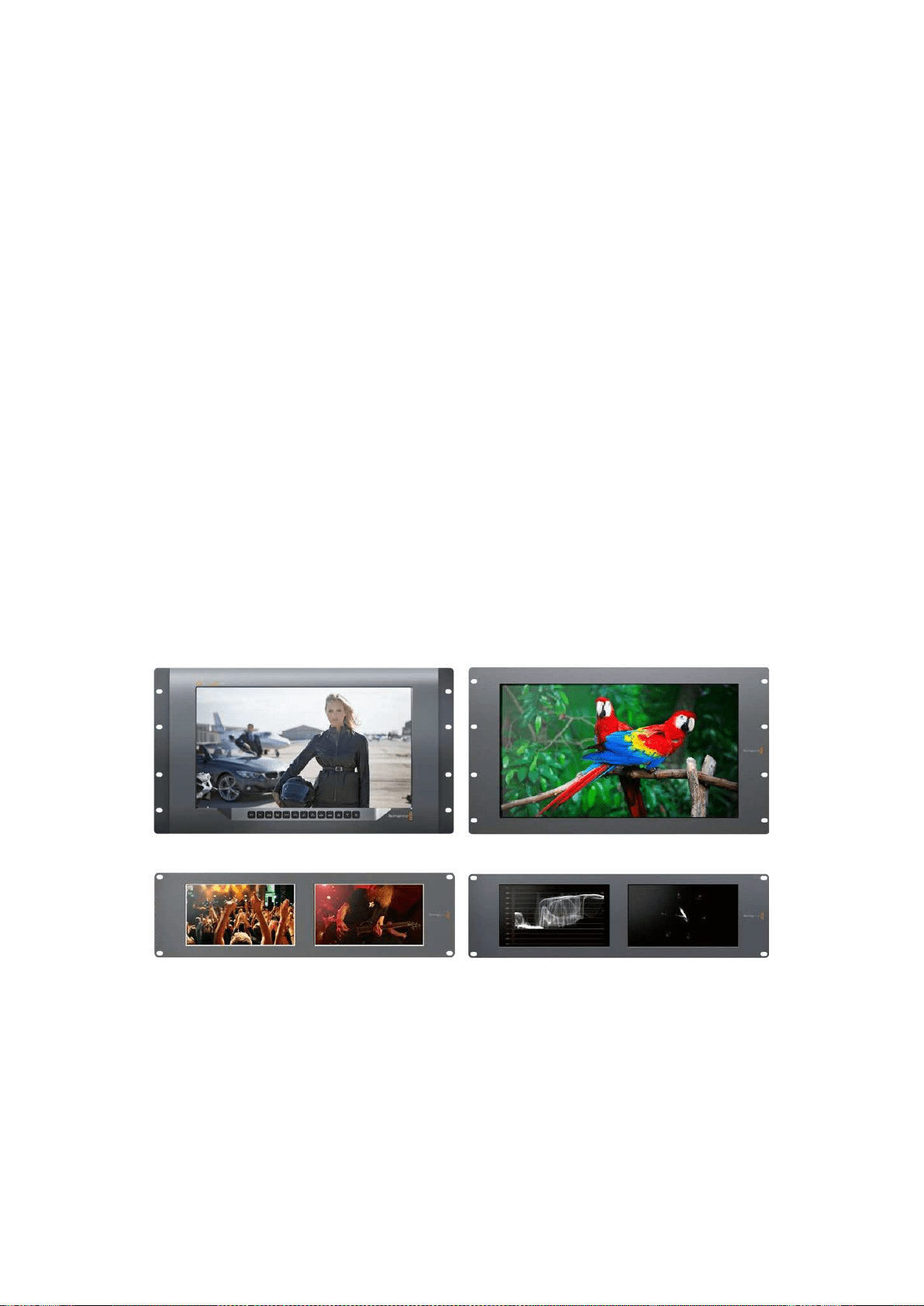
195
入门
入门
SmartView和SmartScope产品简介
SmartView
监视器可完美纳入各类机架式监看设备中。只需通过简单步骤连接电源和
SDI
视频
源便可开始监看工作!
SmartView
4K
配有一块
15.6
英寸
4K
LCD
显 示 屏 ,能 以 原 生
3840x2160
像素分辨率监看
SD
、
HD
或
Ultra
HD
视频。此外,它还设有前面板控制按钮,能轻松选择输入,调节屏幕亮度、检查蓝色通道噪
点 ,查 看 消 隐 信 息 ,以 及 应 用
3D
LUT
等多项功能。
SmartView
HD
配有一块
17
英寸
LCD
显示屏,能以全分辨率提供精准的
HD
监看。
SmartView
Duo
配有两块监视屏,可同时显示不同视频信号。例如,一块显示屏可显示
YUV
4:2:2
信
号,而另一块则可接收
RGB
4:4:4
信 号 。或 者 一 块 显 示
NTSC
制 式 ,另 一 块 显 示
PAL
制式。各款设备可
有各种不同组合,但都只需要单根
SDI
线缆分别连接各监视器即可!
SmartScope
Duo
4K
和
SmartView
Duo
功能一样,但是前者还可实时显示波形、矢量图及其他常见
波形,用于监测视音频的各项指标。此外,它还全面支持
Ultra
HD
4K
!
SmartView
和
SmartScope
监视器上的所有
SDI
输入接口都支持自动检测
SD
、
HD
或
3G-SDI
,包 括
2K
视频。
SmartView
4K
还可检测包括通过
12G-SDI
输入的
2160p60
等
Ultra
HD
信号。
SmartScope
Duo
4K
则可通过其
6G-SDI
接口自动检测
Ultra
HD
4K
视频。
如果需要从计算机远程调整多台
SmartView
和
SmartScope
的各项设置,只需将设备连接到以太网
即可。这意味着您无需亲自带着电脑和
USB
连接线反复去到机房将它们逐个进行调整了。
准备完毕后便可开始工作了! 有关如何连接
SmartView
和
SmartScope
、如 何 通 过
Blackmagic
SmartView
Setup
软件配置监视器设置以及如何连接网络的具体信息,请继续阅读接下来的章节。
SmartView 4K SmartView HD
SmartView Duo SmartScope Duo 4K
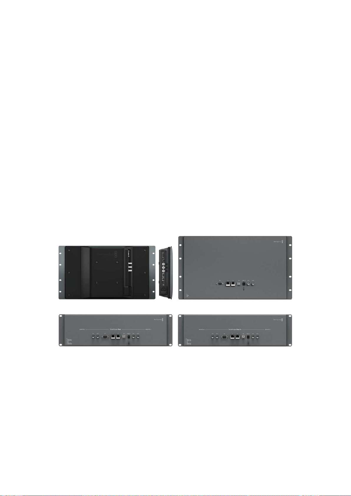
196
入门
连接视频源
SmartView
和
SmartScope
监视器都配有
BNC
接口,可连接的
SDI
设备包括各类切换台、摄影机、采
集卡、录机以及硬盘录机等。
获取画面
显示视频非常简单, 只需开启设备,并将视频源连接到
SDI
输 入 口 即 可 。开 启 并 连 接 到 设 备 后 ,视 频
应可立即显示。
SDI
输入和环通输出接口可自动检测
SD
、
HD
以及
2K
信号。
SmartView
4K
和
SmartScope
Duo
4K
还可检测
Ultra
HD
4K
信号。
当设备未接收到任何视频信号时,背光灯会关闭以节省电源,等接收到下一个信号时再次亮起。
菊链式连接监视器
每台
SmartView
和
SmartScope
监视器都具备其独立的
SDI
输入及环通输出,以便您通过菊链式将多
台监视器连接在一起,显示相同输入信号:
1 开启
1
号 设 备 。将 视 频 源 连 接 到
SDI
输入口。视频应立即显示。
2 开启
2
号 设 备 。用
SDI
连接线从
1
号设备的环通输出口连接到
2
号设备的
SDI
输入口。
连接的设备数量并无限制。
使用
SmartScope
Duo
4K
监 看 波 形 时 ,您 可 能 需 要 将
1
号监视器环通输出到
2
号 监 视 器 ,以 便 两 台 显
示器都可以使用同一个输入信号。
视频显示后,您可以调整监视器设置,或使用
Blackmagic
SmartView
Setup
软件选择需要在
SmartScope
Duo
4K
上显示的波形,该软件还可将
3D
LUT
加载到
Blackmagic
SmartView
4K
上。
SmartView
4K SmartView
HD
SmartView
Duo
SmartScope Duo 4K
连接到计算机
通过
USB
连接到您的计算机并安装
Blackmagic
SmartView
Setup
软件后即可为
SmartView
或
SmartScope
监视器配置各项设置。
USB
接口还可用于执行内部软件更新(软件可从
Blackmagic
Design
网站下载)。软件更新后可获得
更多新增功能、更大的硬件兼容力和更多格式支持。
Blackmagic
SmartView
Setup
软件支持
macOS
和
Windows
计算机。
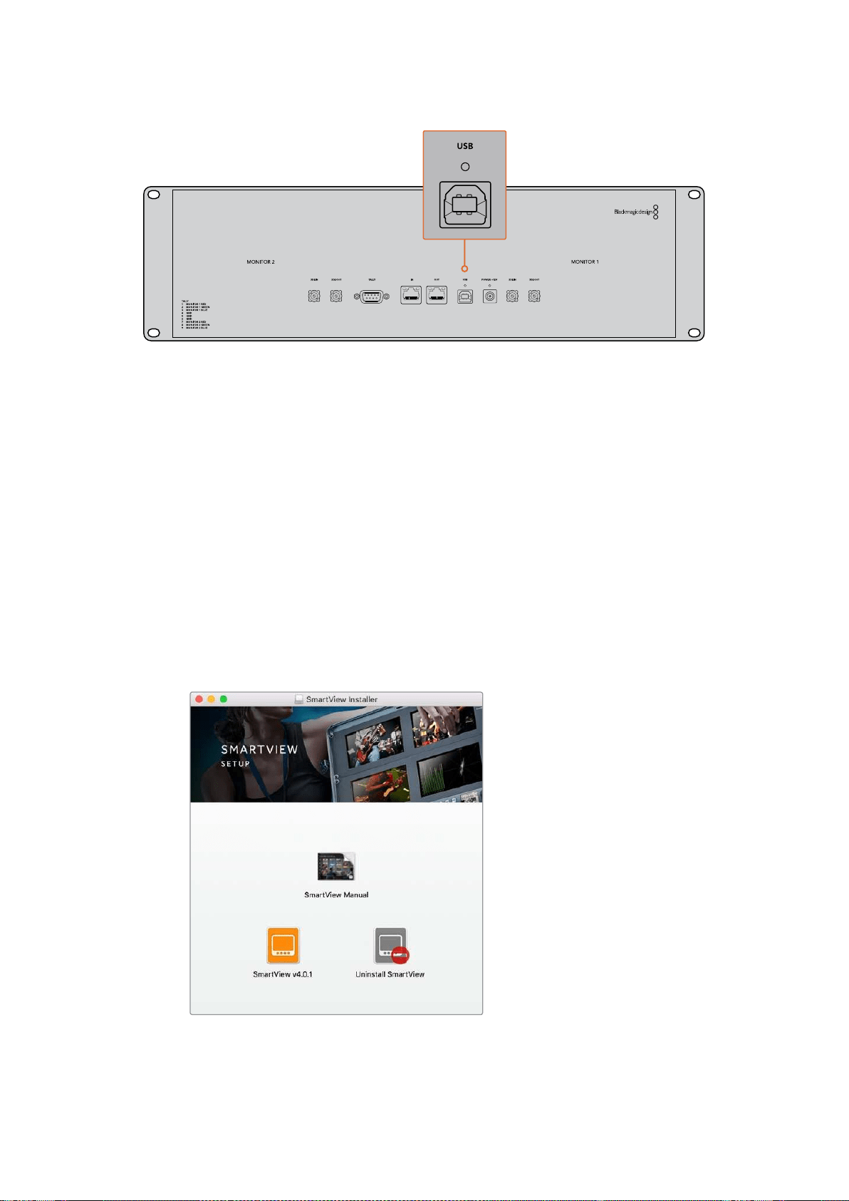
197
入门
安装Blackmagic SmartView Setup
Blackmagic
SmartView
Setup
可在最新的
Sierra
和
High
Sierra
版本
macOS
,以及安装了最新升级服
务包的
64
位版本
Windows
8.1
和
10
系统上运行。如有需要,
Blackmagic
SmartView
Setup
可安装
在多台联网计算机上。
SmartView
自带附有安装程序的
SD
卡,同时,我们仍推荐您访问公司网站
www.blackmagicdesign.
com/cn/support
以确保您安装的是最新版本。
在macOS系统下安装:
打开自带的
SD
卡后者下载的磁盘图像,然后双击安装
SmartView
图标。系统会在您的“应用程序”
文 件 夹 下 创 建 一 个 名 为“
Smartview
”的 文 件 夹 ,当 中 含 有
SmartView
Setup
软 件 ,一 个 卸 载 程 序( 更
新时用于移除旧版本),以及一个含有本操作手册以及
SmartView
其他信息的文档文件夹。
在Windows系统下安装:
在
Windows
系 统 下 ,打 开 内 附
SD
卡或点击下载后的压缩文件,然后双击
SmartView
安 装 程 序 。请 根
据屏幕提示完成软件安装。
如果在
macOS
系 统 下 安 装 ,请 运 行 内 附
SD
卡或下载文件夹中的
SmartView.dmg
文 件 ,然 后 双 击
SmartView
安装图标
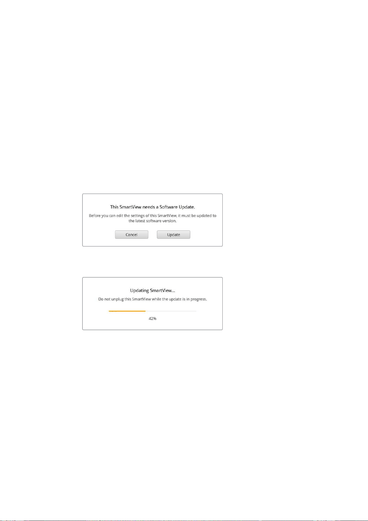
198
使用
Blackmagic
SmartView
Setup
使用
Blackmagic
SmartView
Setup
软件更新
安装并运行
Blackmagic
SmartView
Setup
后,点击监视器名称下方的设置图标。该软件可能会提示
您更新
SmartView
或
SmartScope
的 内 部 软 件 。具 体 操 作 步 骤 如 下 :
1 通过
USB
接口或以太网将
SmartView
或
SmartScope
和 计 算 机 连 接 ,然 后 运 行
Blackmagic
SmartView
Setup
。
2 弹 出 对 话 框 之 后 ,点 击“
Update
”(更新)。更新过程可能需要
5
分钟左右。
3 更新完成后会弹出 “
This
SmartView
has
been
updated
”(
SmartView
已 完 成 更 新 )消
息 ,提 示 您 更 新 已 完 成 。
4 点 击“
Close
”( 关 闭 ) 。
如果无需升级内部软件,
Blackmagic
SmartView
Setup
会打开监视器设置页面。
运行
SmartView
Setup
并打开所连接
SmartView
或
SmartScope
的设置图标时,如果需要进行内部软件更
新 ,系 统 会 弹 出 以 上 信 息 。
更新过程可能需要
5
分钟左右。
调整监视器设置
Blackmagic
SmartView
Setup
打开时会立即搜索任何通过
USB
或者以太网连接的
SmartView
或
SmartScope
设 备 ,并 在
SmartView
Setup
软件主页上显示。如果您的网络中连接了多台
Blackmagic
监视器,请点击主页两侧的左右箭头图标选择需要调整的监视器。如果您的
Blackmagic
监视器是通
过
USB
连接,那么监视器名称边上会显示一个
USB
图标。
调 整 设 置 时 ,请 选 择 通 过 以 太 网 或
USB
连接的监视器,然后点击监视器名称下方的设置图标。该操
作将会打开您所选监视器的设置页面。设置妥善后,请点击“
Save
”按钮来保存您的设置并回到
SmartView
Setup
主页。
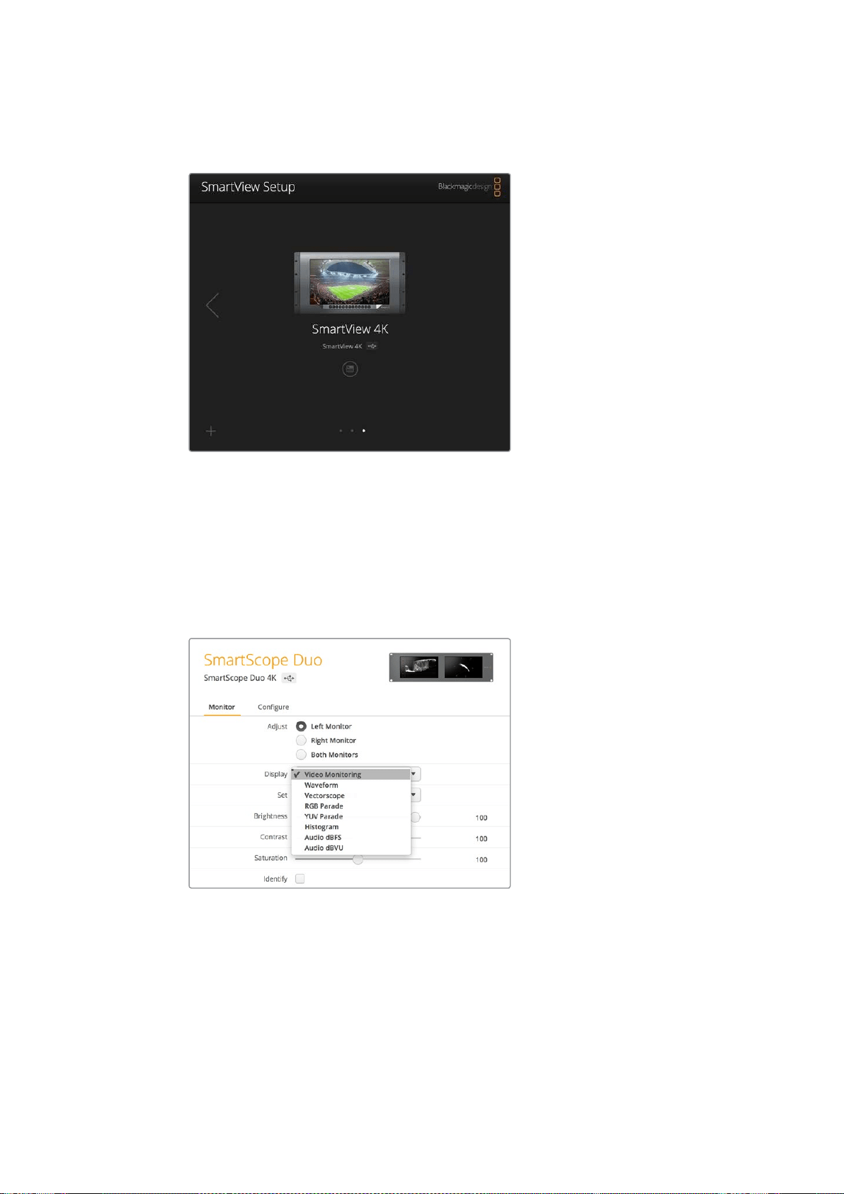
199
使用
Blackmagic
SmartView
Setup
更多关于
Blackmagic
监 视 器 的 可 用 设 置 及 其 应 用 的 内 容 ,请 参 考 下 文 。更 多 关 于 使 用
Blackmagic
SmartView
Setup
配置网络设置的内容,请参考“调整网络设置”章节。
Blackmagic
SmartView
Setup
会自动搜索通过
USB
或网络获得本
地连接的
SmartView
和
SmartScope
设 备 。为 您 的 监 视 器 更 新 内
部 软 件 时 ,请 确 保 监 视 器 通 过
USB
或以太网连接。监视器名称一
旁会出现
USB
图标。
监视屏设置
要为每台监视器调整设置和显示,请务必通过以太网或
USB
连 接 设 备 。点 击
SmartView
Setup
主页
左右两侧的箭头图标来选择您想要设置的监视器,然后点击监视器名称下方的设置图标。设置页面
将自动进行自定义调整,以便与您所选
Blackmagic
监视器所支持的功能相配套。
如使用
SmartScope
,您可以选择不同波形以及从“
Display
”
(显示)下拉菜单中选择需要监看的视频。
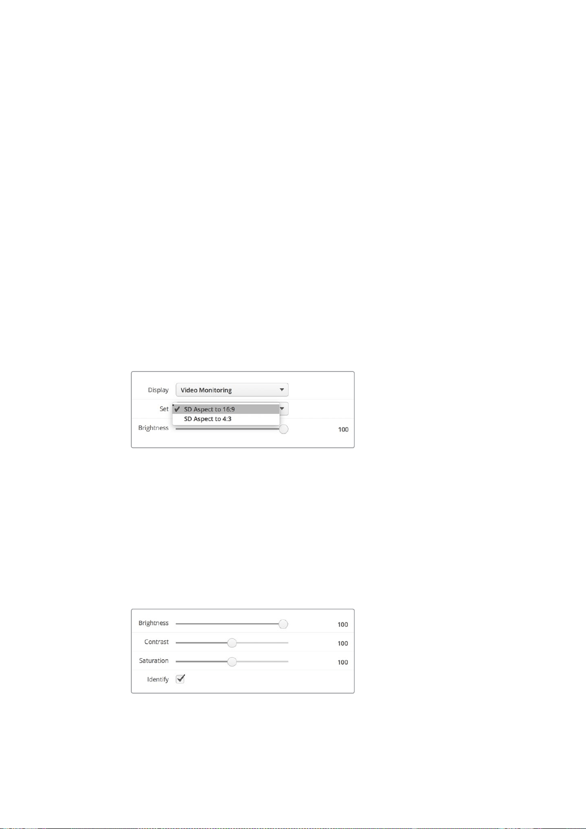
200
使用
Blackmagic
SmartView
Setup
Adjust
(调整)
使用
SmartScope
或
SmartView
Duo
时 ,请 根 据 情 况 勾 选“
Left
Monitor
”( 左 侧 监 视 屏 ) 、“
Right
Monitor
”(右侧监视屏)以及可进行同时调整的“
Both
Monitors
”(两侧监视屏)选项来选择想要调
整 的 监 视 屏 。启 用“
Both
Monitors
”设置之后,所有针对亮度、对比度以及饱和度所应用的调整会对
SmartView
Duo
和
SmartScope
监视器同时生效。
Display
(显示)
使用
SmartScope
时 ,“
Display
”(显示)下拉菜单可提供不同波形供您选择。如要监看视频画面,请
选 择“
Video
Monitoring
”( 视 频 监 看 ) 。
Set
(设置)
使用
SmartScope
监 看 标 清 视 频 时 ,“
Set
”(设置)下拉菜单可用来选择
4:3
或
16:9
宽高比用于视频监
看 显 示 。“
Set
”下拉菜单可为选中显示器提供更多选项,如矢量图、音频
dBFS
以及音频
dBVU
等。
Video
Monitoring
(视频监看):
视频画面监看可在
4:3
或
16:9
宽高比之间选择。
当监看宽屏变形标清视频时,请选择
16:9
宽 高 比 。当 监 看 传 统
4:3
标清视 频时,
请选择
4:3
宽高比。
Vectorscope
(矢量示波器):
请为您的输入选择
100%
或
75%
彩条测试信号。
Audio
dBFS
(音频
dBFS
):
选择一对音频通道来监看相位。
Audio
dBVU
(音频
dBVU
):
选择一对音频通道来监看相位。
监 看 变 形 标 清 视 频 时 ,请 设 置 为“
SD
Aspect
to
16:9
”。
Brightness
(亮度)、
Contrast
(对比度)及
Saturation
(饱和度)
调节滑块可应用不同的亮度、对比度以及饱和度设置。
识别监视器
启 用“
Identify
”( 识 别 ) 复 选 框 时 ,
Blackmagic
SmartView
Setup
中的所有选定监视器均会显示白
色边框。通过网络连接多台
SmartView
和
SmartScope
设备时,使用这一设置后所选监视器可一目了然。
如果使用这一设置的同时结合使用“
Both
Monitors
”( 两 侧 监 视 屏 ) 选 项 , 那 么
SmartView
Duo
或
SmartScope
Duo
4K
的两块监视屏上会同时显示白色边框。
左右拖动滑块调节亮度、对比度以及饱和度设置。
检 查“
Identify
”(识别)设置,以便清楚查看到您所选择的监视器。
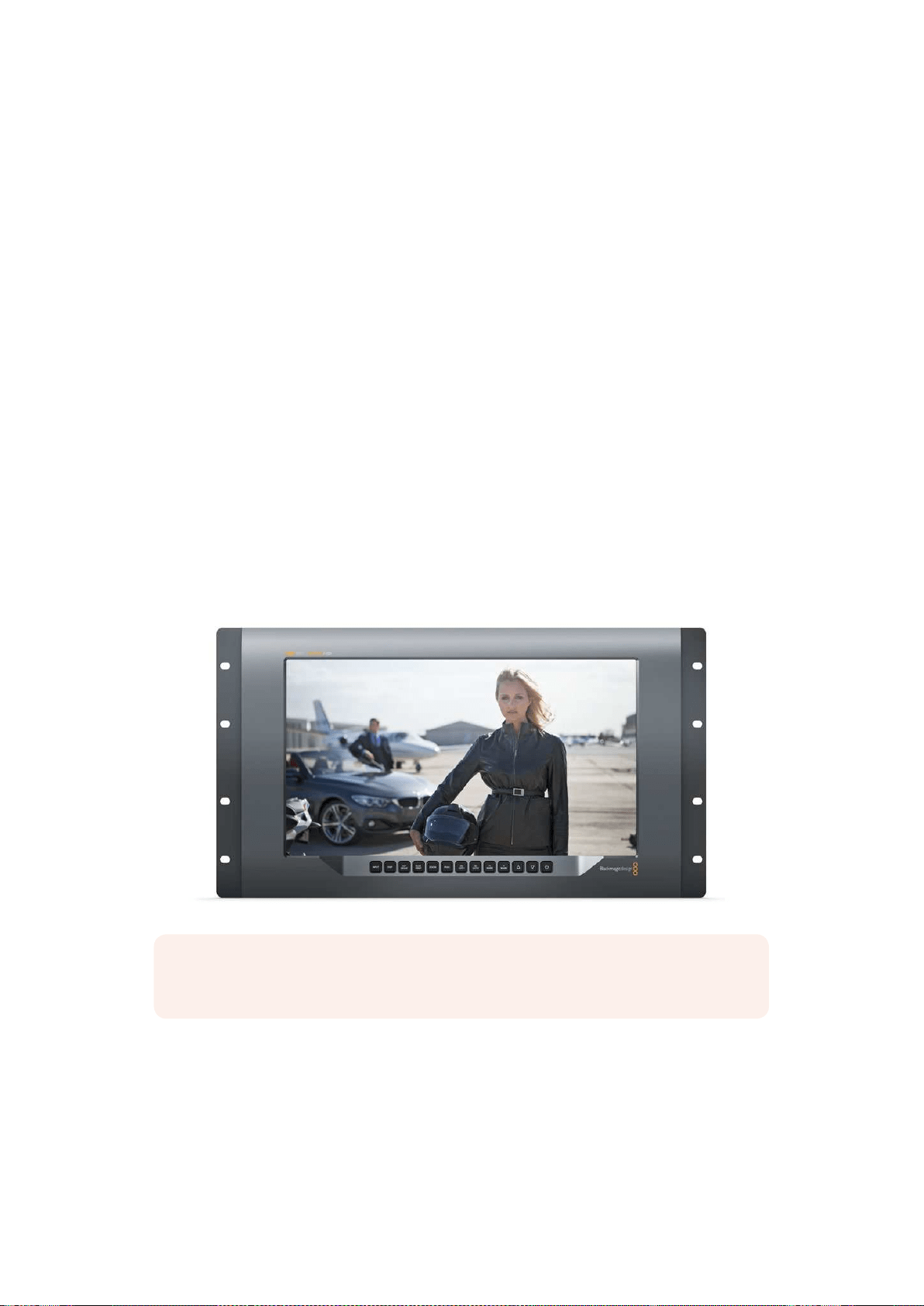
201
使用
SmartView
4K
使用
SmartView
4
K
Blackmagic SmartView 4K简介
SmartView
4K
是一款
6RU
大小的
Ultra
HD
12G-SDI
广 播 级 监 视 器 ,可 显 示
SD
和
HD
影 像 ,并 可 查 看
高达
2160p60
的
Ultra
HD
视频。这款监视器拥有明亮的显示屏和超宽可视角度,画面生动清晰,能
为您带来准确对焦和色彩监看,并支持几乎任何视频格式。
SmartView
4K
专为演播厅和户外播出环境设计,使用极其便捷。它的两侧设有众多接口,并支持
VESA
安装标准,可安装在狭小空间,或固定于墙面以及显示器支架上。
SmartView
4K
可通过其内
置的控制面板进行操控,当您无法触及前面板时,它也可通过以太网实现远程控制。
它设有两个多速率
12G-SDI
输 入 ,可 选 择 两 个
SDI
信 号 源 ;一 个
SMPTE
兼容
SFP
模 块 槽 ,可 用 于 添 加
光纤
SDI
模块从而通过光纤连接视频; 一路
12G-SDI
输出,以便将视频信号连接到其他设备上;两
个以太网接口,用于网络连接、远程控制以及和其他监视器通过菊链式连接在一起实现环通输出。
其他接口还包括用于现场制作的
Tally
输 入 接 口 ,以 及 用 于 内 部 软 件 更 新 的
USB
端口。
您甚至可以使用
Blackmagic
SmartView
Setup
软件来加载带有
.cube
扩展名的行业标准
3D
LUT
或
DaVinci
Resolve
生成的
LUT
! 有了
3D
LUT
,您 就 可 以 将 您 的
SmartView
4K
直接连接到摄影机上,
以尽可能接近调色成品的画面查看拍摄片段。
SmartView
4K
拥 有 两 个 级 别 的 峰 值 对 焦 设 置 ,可 确 保
您的拍摄镜头完美对焦。此外,它同时支持
AC
和
DC
电源,可提供不同电源连接选择,让您直接连接
主电源,或连接外部电池,在工作现场获得便携方案。
SmartView
4K
是便携式以及演播室播出制作的完美监看方案,能以原生
3840x2160
像素分辨率显
示
SD
、
HD
以及
Ultra
HD
视频。
备注
:
如果通过
DC
电源输入连接了外部电源,请确保您的外部电源输出可提供
24
瓦
12
伏
电源。
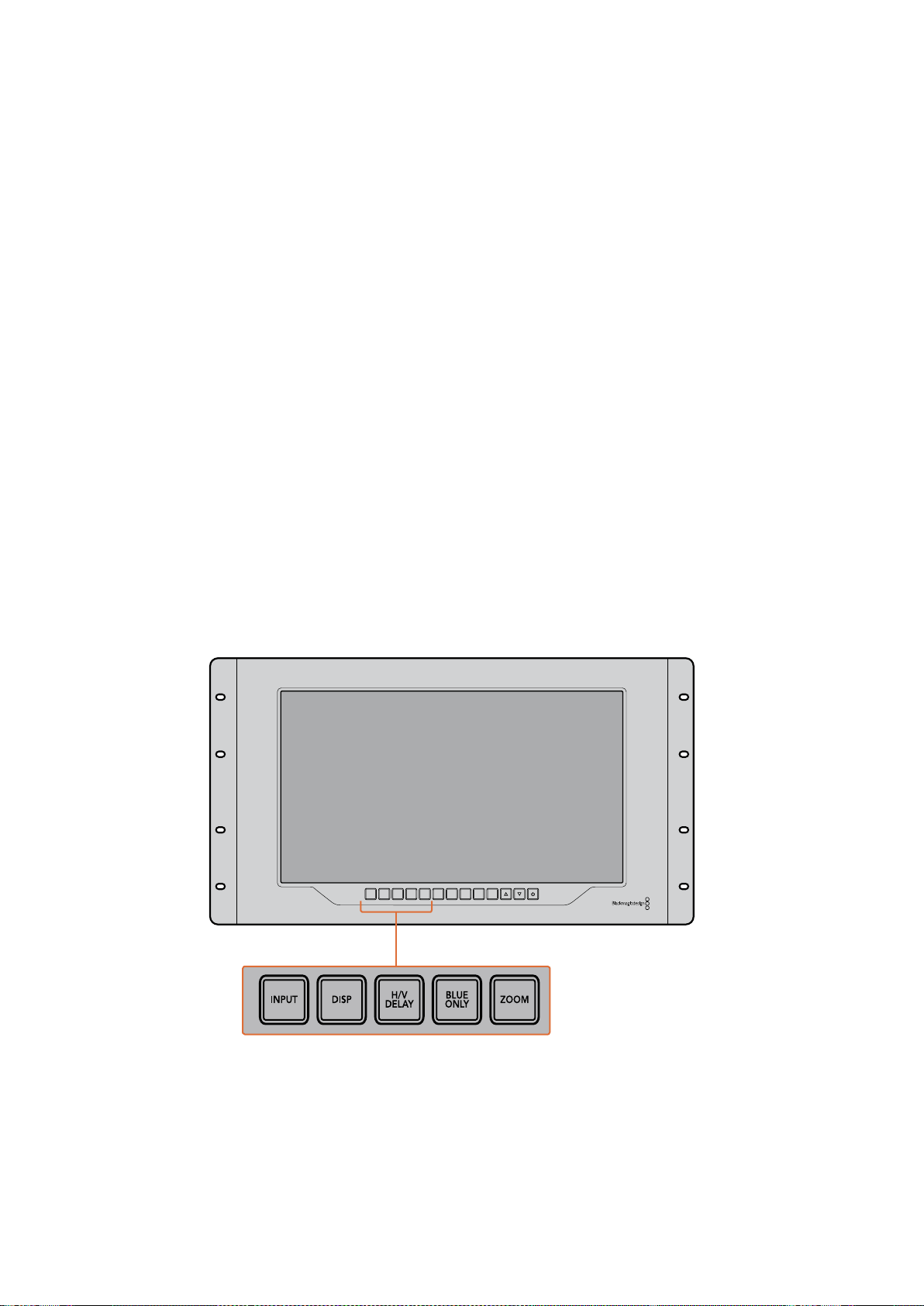
202
使用
SmartView
4K
控制面板按钮
SmartView
4K
的控制面板配有一排按钮,可快速调整监视器的设置。
Input(输入)
按此按钮可逐个浏览所有连接到
SmartView
4K
两路
12G-SDI
输入接口以及选配光纤
SFP
模块输入接
口上的视频信号。如果某路输入接口上未连接任何视频,
SmartView
4K
将为该路输入显示为黑屏。
在各路输入间切换时,所连接的输入信号格式信息将短暂显示在监视屏左上角。
DISP(显示)
“
DISP
”按 钮 可 用 来 调 整
SmartView
4K
监视器
LCD
屏幕的亮度设置。按向上和向下箭头按钮可调整
亮 度 。再 次 按 下“
DISP
”按 钮 可 关 闭 该 设 置 。
H
/
V DELAY(水平
/
垂直延迟)
按 下“
H/V
DELAY
”按 钮 可 快 速 确 认 您 的
SDI
视频信号中嵌入的辅助数据。举例说明,按“
H/V
DELAY
”
按钮一次可查看水平辅助数据。再次按下“
H/V
DELAY
”按钮可查看垂直辅助数据,该数据常用
于隐藏式字幕等数据。
BLUE ONLY(纯蓝模式)
如果数字视频信号中出现噪点,蓝色通道可显著体现出这一信息。您可以按下“
BLUE
ON LY
”按 钮
通过蓝色通道来轻松检查噪点情况。这一模式可仅显示纯蓝通道,并以黑白图像的形式表现。这一
黑白图像还可在检查摄影机对焦时起到辅助作用。
ZOOM(缩放)
使 用“
ZOOM
”按钮可令摄影机获得清晰对焦。按此按钮一次可放大图像, 以便清晰查看拍摄主体
是否精准对焦。再次按下该按钮可回到正常查看大小。
INPUT DISP
H/V
DELAY
3D
LUT 1
BLUE
ONLY
ZOOM PEAK
3D
LUT 2
H
MARK
V
MARK

203
使用
SmartView
4K
PEAK(峰值)
按“
PEAK
”按钮可启用峰值对焦功能,轻松检查摄影机对焦。该功能可在画面中锐度最高的部分显
示明亮的绿色边缘。峰值对焦强度共有两个级别,您可以连续按下“
PEAK
”按 钮 加 以 切 换 。当 绿 色
边缘采用最强级别时,您可以确保摄影机对焦。
3D LUT 1和3D LUT 2
这两个
LUT
按钮可使用
Blackmagic
DaVinci
Resolve
生成的自定义
3D
LUT
或者行业标准
.cube
LUT
查 看 画 面 。按 其 中 一 个
LUT
按钮一次可启用该
LUT
。再次按下该按钮可禁用该
LUT
。更 多 关 于 如 何 在
SmartView
4K
上使用
3D
LUT
的 信 息 ,请 查 阅“ 使 用
Blackmagic
SmartView
Setup
加载
3D
LUT
”部 分 的 内 容 。
H MARK(水平标记线)和V MARK(垂直标记线)
您 可 以 使 用“
H
MARK
”和“
V
MARK
”按钮来查看并编辑帧导栏。帧导栏能帮助您进行镜头取景和
构图,还能将重要信息或图文保持在屏幕安全区。由于不同型号的电视机会显示更多或更少的视频
信号边缘,因此查看安全区是一项非常有用的功能。安全区指的是不论使用何种型号的电视机或监
视器,其屏幕中都能始终查看到的画面区域。
要 查 看 水 平 和 垂 直 帧 导 栏 ,可 分 别 按“
H
MARK
”和“
V
MARK
”按钮。要编辑帧导栏,请再次按下相
应的按钮使该帧导栏高亮显示即可。这样您就能使用上下箭头来编辑每个帧导栏标记的位置了。连
续按下每个相应按钮将确认您编辑的新位置。再次按下相应按钮可关闭帧导栏标记。
上下箭头按钮
当您编辑某项设置,例如调整显示器亮度或编辑帧导栏位置时,可使用上下箭头按钮。
功耗
按电源按钮一次可开启
SmartView
4K
。再 次 按 下 可 关 闭 设 备 。
INPUT DISP
H/V
DELAY
3D
LUT 1
BLUE
ONLY
ZOOM PEAK
3D
LUT 2
H
MARK
V
MARK
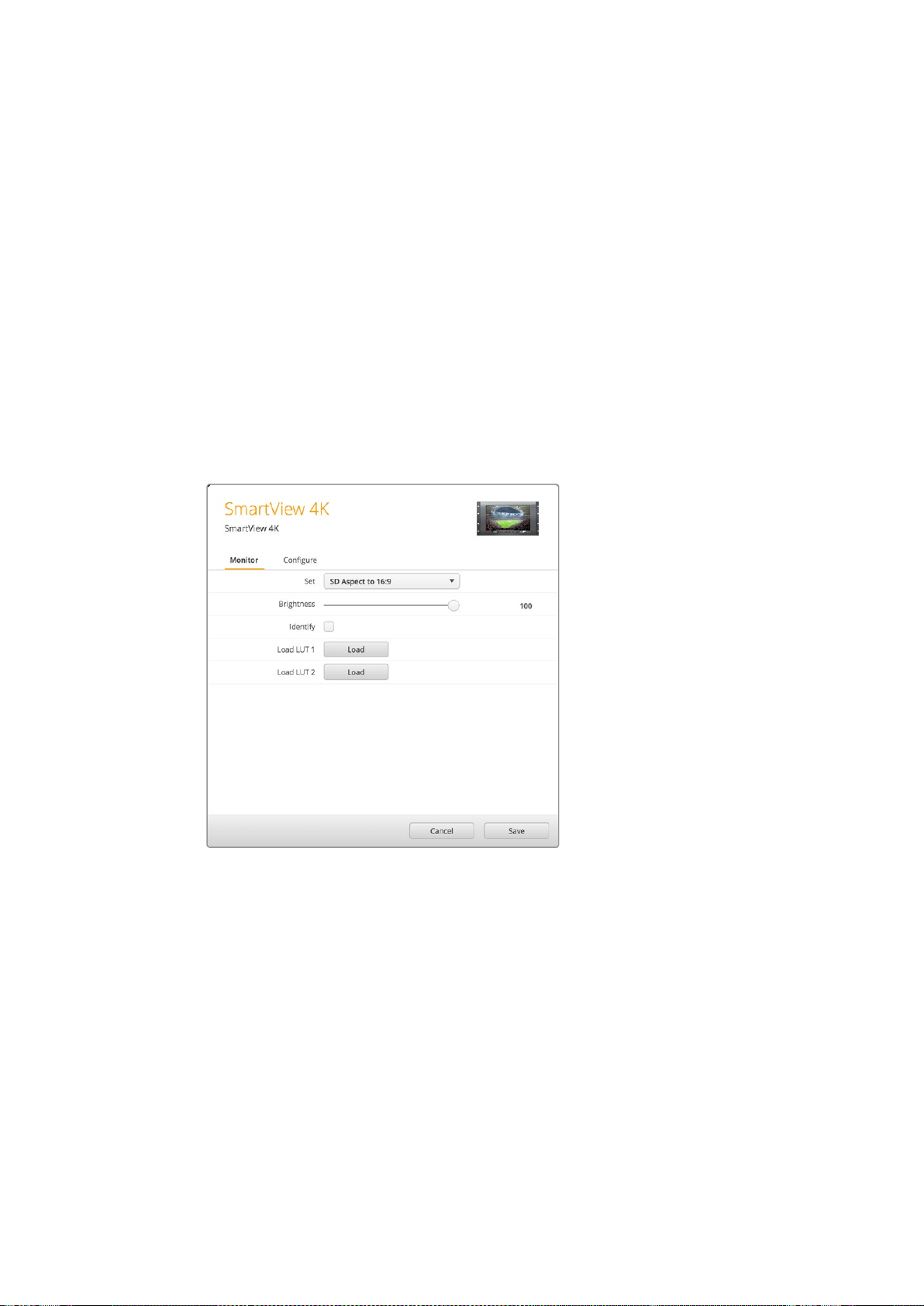
204
使用
SmartView
4K
使用Blackmagic SmartView Setup加载3D LUT
SmartView
4K
可使用
3D
LUT
来监看您的视频。这样能便于您使用专业的校准
LUT
来校准您的
SmartView
4K
,或者以尽可能接近最终调色成品的画面来查看您的视频。您还能使用
3D
LUT
来尝
试不同画面风格。
LUT
可通过
Blackmagic
SmartView
Setup
软件加载到
SmartView
4K
上 。此 外 ,由
于
SmartView
4K
支持以
.cube
作为文件扩展名的行业标准
LUT
文 件 ,您 甚 至 还 能 加 载 由
Blackmagic
DaVinci
Resolve
生成的自定义
LUT
。更 多 关 于 生 成
LUT
文 件 的 信 息 ,请 查 阅
DaVinci
Resolve
操作手册。
将一个3D LUT加载到3D LUT 1:
1 运行
Blackmagic
SmartView
Setup
。
2 按“
Load
LUT
1
”加载按钮。系统将弹出窗口询问您想要加载的
LUT
文件的位置。选择相应
的
.cube
LUT
文 件 ,然 后 按“
Open
”( 打 开 ) 按 钮 。
3 要查看您刚才加载的
LUT
,可 按
SmartView
4K
控制面板上的“
3D
LUT
1
”按 钮 。再 次 按 下
该按钮可关闭相应
LUT
。
请使用相同步骤将一个
LUT
文件加载到
3D
LUT
2
中。
使用
Blackmagic
SmartView
Setup
在
SmartView
4K
上加载
3D
LUT
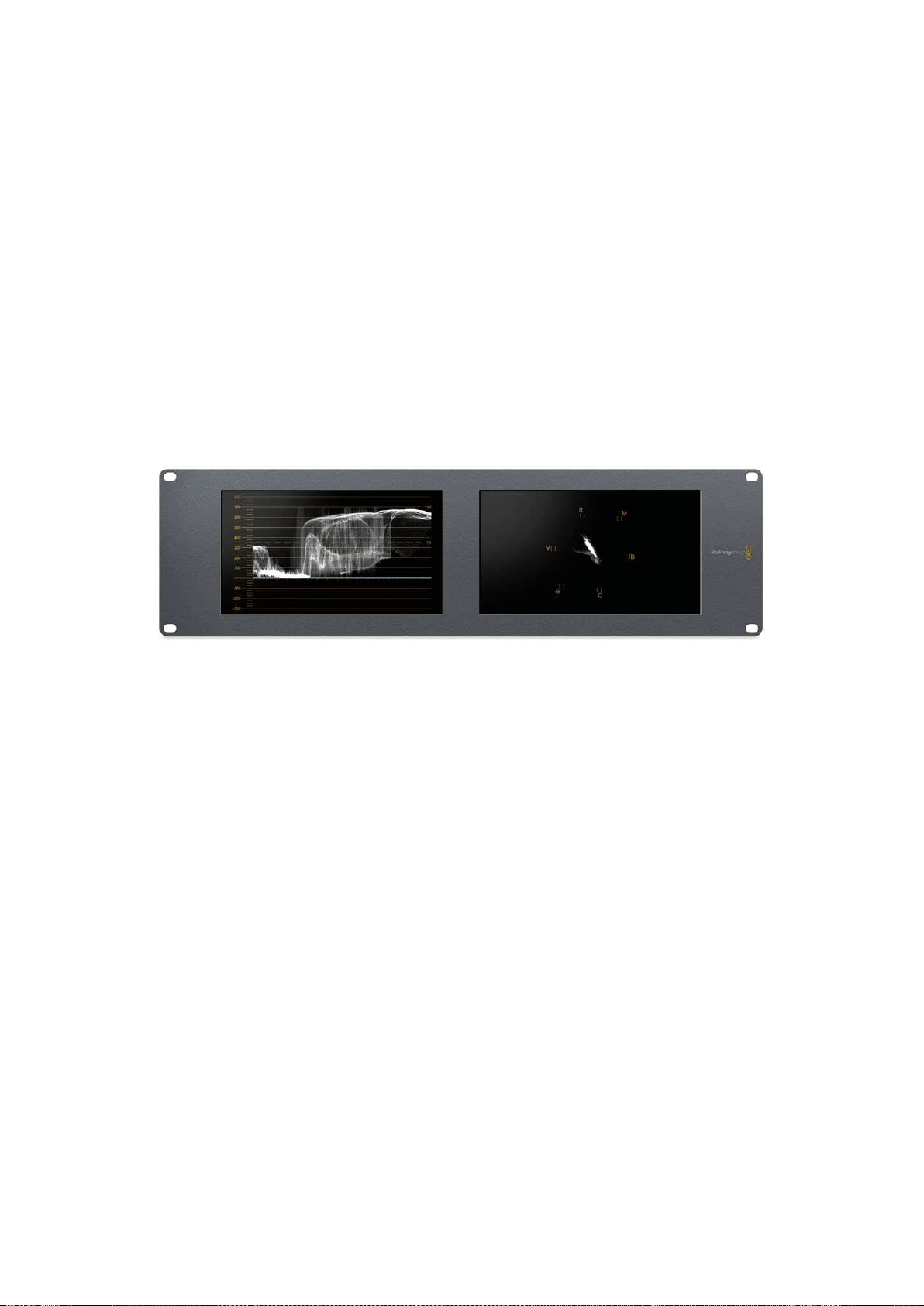
205
使用
SmartScope
Duo
4K
使用
SmartScope
Duo
4
K
什么是Blackmagic SmartScope?
以前,广播级电视机和后期制作示波器都是非常昂贵的自定义方案,而且它们一次只能监看一种波
形,屏幕也十分狭小。有些示波器外形欠佳,无法向客户展示。
有了
SmartScope
Duo
4K
,您 可 以 再 获 得 额 外 的 波 形 监 视 器 ,通 过 两 块 监 视 屏 实 时 监 看 视 频 信 号 的
各类指标。您在
Blackmagic
SmartView
Setup
中对输入信号所做的任何调整都能立即通过
SmartScope
Duo
4K
查看到。此外,每路输入信号都可经由
SDI
环通输出到任意一个监视屏上,也就是说,您可以
使用左边的监视屏接收信号,使用右边的监视屏显示该信号的波形。
SmartScope
Duo
4K
所显示的波形可通过
Blackmagic
SmartView
Setup
软 件 选 择 。从“
Display
”
(显示)下拉菜单中选择需要监看的波形。
接下来的几页中,本手册会向您介绍各类波形的含义及用途,以便您进一步了解并对其加以充分利用。
使用
Blackmagic
SmartView
Setup
软件可简单地将您的
BlackmagicSmartScope
Duo
4K
设置成在每块显
示屏上显示不同波形。
视频监看显示
Video
Monitoring
(视频监看)显示具有准确和便捷的特点,您可以监看到
SmartScope
接收到的视频。
如果输入信号是
SD
,那 么 在“
Set
”(设置)下拉菜单中有“
4:3
Pillarbox
”或“
16:9
”两种显示模式可
以 选 择 。您 对
LCD
屏 幕 的“
Brightness
”( 亮 度 ) 、“
Contrast
”( 对 比 度 ) 或 “
Saturation
”( 饱 和 度 )
所做的任何更改都会立即体现在画面上。请注意,这些设置改动只对监视屏有效,并不会影响视频
信号。因此各类波形也不会因为改变了饱和度或亮度等而受到影响。

206
使用
SmartScope
Duo
4K
您还能将其中一个监视屏设置成“
Video
Monitoring
”(视频监看),而另一个监视屏用于监看波形。
要进行这一操作,请使用一根短连接线将“
MONITOR
1
”这 一 侧 的
SDI
OUT
环通输出接口连
接“
MONITOR
2
”这 一 侧 的
SDI
IN
输入接口。
您可以在
Blackmagic
SmartView
Setup
软 件 的“
Set
”选 项 中 进 行 选 择 ,
从而以
4:3
左右加黑边或
16:9
宽屏模式来查看
SD
视频。
监 看 变 形 标 清 视 频 时 ,请 设 置 为“
SD
Aspect
to
16:9
”。
“
Video
Monitoring
”(视频监看)显示设置能呈现电视机或监视器屏幕所显示的视频信号。
波形显示
“
Waveform
”(波形)显示可提供和传统亮度波形监视器类似的数字编码波形,可用于监看和调整
视频信号的亮度电平指标。
传统的亮度波形监视器只支持复合模拟标清视频。但是,
SmartScope
Duo
4K
显示的波形视图支持
Ultra
HD
、
HD
和
SD
,因此即使您在监看高清数字视频格式时也可以轻松调整亮度电平从而确保一致。
从
Blackmagic
SmartView
Setup
软 件 的“
Display
”(显示)下拉菜单中选择波形。请务必确保波形
中的黑色部分不低于
0%
,白 色 部 分 不 高 于
100%
,否则会存在非法亮度值。
波形监视器可将画面信息以图形的方式呈现出来,显示画面中相同位置所对应的亮度值。举例说明,
如果图像中的天空部分出现过曝现象,那么波形图中的相同水平位置会相应体现出来。
不同的视频素材,其波形显示各有不同。如果您监看的视频具有高对比度,那么波形图中可能不会
显示任何中灰色数值。下图所示的是曝光均匀的图像波形,该图左侧有一小块黑色区域,而较为明
亮的部分则分布在画面中部到右部。

207
使用
SmartScope
Duo
4K
波形视图可反映出亮度值
在
Blackmagic
SmartView
Setup
的“
Display
”( 显 示 )
设 置 中 选 择“
Waveform
”(波形)选项来查看您视频信号中的亮度值信息。
矢量示波器
“
Vectorscope
”(矢量)示波器以矢量视图方式体现视频信号中的不同颜色。请根据设备所使用的
彩条测试信号标准,从
Blackmagic
SmartView
Setup
的“
Set
”(设置)下拉菜单中相应选择
100%
或
75%
。
有些使用者认为矢量示波器可用来检查非法电平,这一认识是错误的。非法色彩需使用分量
RGB
波形
显示才能检查。因为您需要同时有色度和亮度两种信息才能检查非法电平,所以矢量示波器并不适用。
例如,视频中接近黑场和白色的颜色饱和度没有浓艳的色彩饱和度高,这些色彩可在中性灰中使用。
由于
Vectorscope
(矢量示波器)只显示颜色,并非亮度数值,因此无法用于专门检查非法色彩。
矢量示波器显示最适合用来检查老式模拟录像带中的色彩电平,以帮助您调整色度电平。请先播放
录像带中彩条的部分,然后调整色度和色相设置,将视频的各个色彩限定在刻度线内的方格中。
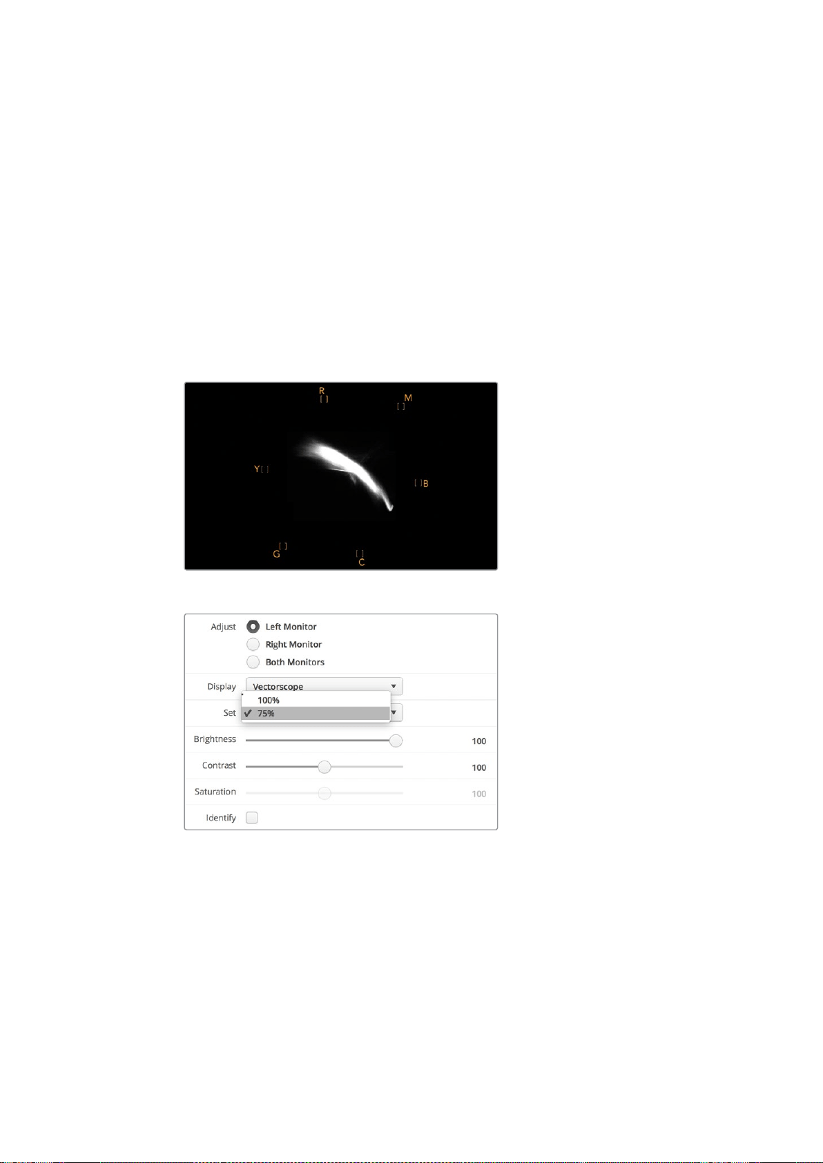
208
使用
SmartScope
Duo
4K
此外,矢量示波器还十分适合进行调色时使用,因为它能直观地告诉您视频的白平衡设置是否正
确,以及是否出现偏色。如果视频存在偏色现象,矢量示波器显示会从中间向外偏移,您可能会见
到两个中心点。通常情况下,消隐的视频信号会在矢量示波器中心形成一个点,这是因为消隐的视
频是不带任何色彩黑场视频。消隐可提供十分有用的参照点,有助于识别出无任何色彩
信息的黑场视频区域。
如果您的视频存在偏色问题,就会发现矢量示波器中的暗部会偏离色彩并偏离中心。偏离的程度代
表了视频中偏色的程度,您可以看到视频中亮部和暗部细节部分的偏离情况。因此
Vectorscope
(矢量示波器)显示能移除偏色并重新得到恰当的白平衡值。
矢量示波器能让您使视频中的颜色看起来尽可能艳丽,但不会不小心在暗部和亮部造成不必要的偏色。
虽然色彩平衡可通过
RGB
分量显示以及矢量示波器显示监看,但是通常后者较易发现色彩平衡问题。
当为素材中的肤色部分,尤其是人物面部进行调色时,请尽量将矢量示波器中的暖色调饱和度线条
与指向十点钟方向的轴线对齐。这条轴线俗称“
Fleshtone
Line
”(肤色轴线),它是以皮肤表层下的
血色为基准的。因此,肤色轴线可用于针对肤色瑕疵的校准,让演员的拥有自然肤色。
图中的矢量示波器显示出指向十点钟方向的“肤色轴线”。
将“
Vectorscope
”( 矢 量 示 波 器 ) 设 置 为
100%
或
75%
彩条测试信号。
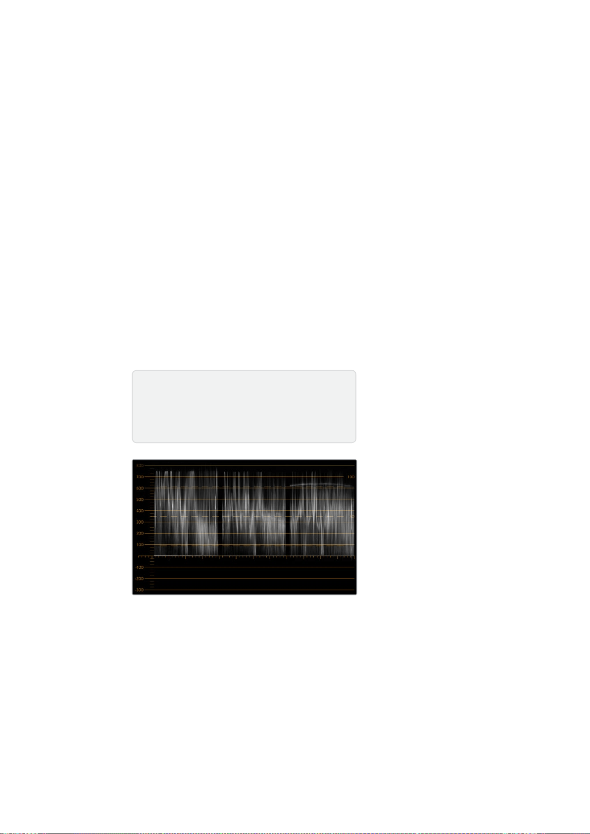
209
使用
SmartScope
Duo
4K
分量示波器
RGB
和
YUV
分量显示十分适合调色、检查非法色彩以及检查电平时使用。
调 色 时 ,从
Blackmagic
SmartView
Setup
的“
Display
”( 显 示 ) 下 拉 菜 单 中 选 择 “
RGB
Parade
”(
RGB
分 量 )。
RGB
Parade
(
RGB
分量)视图将单独显示红、绿、蓝色彩通道的全高图。能对每个通道进行
单独监看使得调色变得简单直接,而且也能更容易检查视频信号中暗部、中间调以及亮部的平衡。
RGB
Parade
(
RGB
分量)能让您注意到红、绿、蓝色彩通道中常见的各个细节,从而更好地控制
色彩平衡并移除偏色。
调色的时候有一点很重要,就是要确保视频的电平达到饱满但不出现限幅现象。如果您想要提高视
频 电 平 ,请 务 必 确 保 其 不 超 过
RGB
限度,否则会产生非法电平。虽然有些设备不允许生成非法的
100%RGB
电平,但是还是有设备会依然允许生成非法电平的。
SmartScope
Duo
4K
能在产生非法
电平时予以即时反馈。
黑电平和白电平都有可能出现非法视频。有些调色系统可以把黑电平降低到
0%
黑 场 以 下 。如 果 发 现
非 法 黑 电 平 ,只 需 调 高“
Lift
”或“
Gain
”即 可 消 除 非 法 黑 电 平 ,同 时 请 检 查
100%
刻 度 ,以 确 保 整 体 视
频信号的亮部未超标并产生非法色彩。
若要检查
YUV
电 平 ,请 在“
Display
”( 显 示 ) 下 拉 菜 单 中 选 择 “
YUV
Parade
”(
YUV
分 量 )。这 一 视 图
非 常 有 用 ,因 为 它 把
Luma
( 亮 度 值 )和
Chroma
( 色 度 值 )分 开 了,这 正 是 电 视 播 出 机 构 视 频 信 号 的
格式。左边的波形表示亮度信息,第二个和第三个波形显示色度信息。
YUV
分量视图很适合将视频
信号的色度值和彩条测试图案进行校准,从而确保色彩准确性,以便让播出信号可以在电视机上显示。
调色是不断调整颜色达到最佳图像效果,并保证不出现非法电平的过程。
RGB
分量视图
调色术语
暗部
–
视频信号中的黑电平
中间调
–
视频信号中的中灰电平
亮部
–
视频信号中的白电平

210
使用
SmartScope
Duo
4K
YUV
分量视图
从
Blackmagic
SmartView
Setup
的“
Display
”( 显 示 ) 下 拉 菜
单 中 选 择“
RGB
Parade
”(
RGB
分 量 示 波 器 )或“
YUV
Parade
”
(
YUV
分 量 示 波 器 )。
直方图显示
“
Histogram
”(直方图)显示对于平面设计师以及摄影师来说并不陌生。直方图反映的是亮部和暗
部信息的分布,让您能监看到视频中亮部和暗部细节接近被限幅的程度。直方图能让您直观地监测
到视频中
Gamma
值的变化所产生的影响。
视频暗部显示在屏幕左侧,亮部显示在右侧。视频在直方图中的波形一般都介于
0%
到
100%
区间。
视频的波形低于
0%
或超过
100%
的部分都会被限幅。拍摄时应尽量避免出现视频限幅,因为如果您
之后需要进行较好的调色,那么画面中暗部和亮部的细节必须要同时保留。拍摄时,将视频波形控
制在黑场裁切以上,白场裁切以下,这样才能在之后的调色环节获得最大限度的还原力,避免出现
暗部和亮部模糊以及细节丢失的问题。
调色时,您可能需要对视频进行限幅,此时直方图可反映视频限幅后的效果及限幅的幅度。您甚至
可使用
Gamma
曲线来达到类似效果,减少限幅的同时保留更多细节。
虽然直方图可用来观察暗部和亮部的非法信息,但是它不能用于监看非法电平。直方图并不显示颜色,
因此即使您的视频中存在非法色彩,它也只显示合法电平。
RGB
Parade
(
RGB
分 量 示 波 器 )才 是 最 适
合监看非法色彩电平的波形显示,因为它能反映视频信号中的色彩和亮度两种元素。

211
使用
SmartScope
Duo
4K
“
Histogram
”(直方图)设置可显示视频中亮部到暗部的信息分布。
从
Blackmagic
SmartView
Setup
软 件 的“
Display
”( 显 示 )
下 拉 菜 单 中 选 择“
Histogram
”( 直 方 图 ) 显 示 。
音频表显示
“
Audio
”音 频 表 显 示 可 以 告 诉 您
SDI
视频信号中嵌入音频的电平。共有多达
16
组嵌入式音频可被解
嵌 ,并 能 以
dBVU
或
dBFS
格式显示。
VU
表可显示平均信号电平,它使用方便,在老式设备中也较为常用。
VU
表依照
SMPTE
(电影电视工
程 师 协 会 )建 议 的 基 准 电 平 ,将
1kHz
的声音测试信号校准为
-20
dBFS
。
dBFS
是衡量数字音频信号整体情况的必要工具,它在如今的数字设备中十分常见。
右侧的音频示波器可监看两个声道,您可通过“
Set
”下 拉 菜 单 中 选 择 例 如
1
号和
2
号声道、
3
号和
4
号
声 道 等 。音 频 示 波 器 使 用
X-Y
轴视图来表示,这样您便能清楚查看音频平衡、异相情况以及音频轨
道是单声道还是立体声等。单声道音频表现为一条垂直的“
in
phase
”(同相)直线。如果该直线显
示为横向,这就表示您的音频出现“
out
of
phase
”(异相),并有可能在发送到下游设备时出现音
频 抵 消( 即 音 频 缺 失 )。音 频 相 位 问 题 在 大 型 设 备 中 经 常 出 现 ,通 常 由 错 误 连 接 线 缆 导 致 。
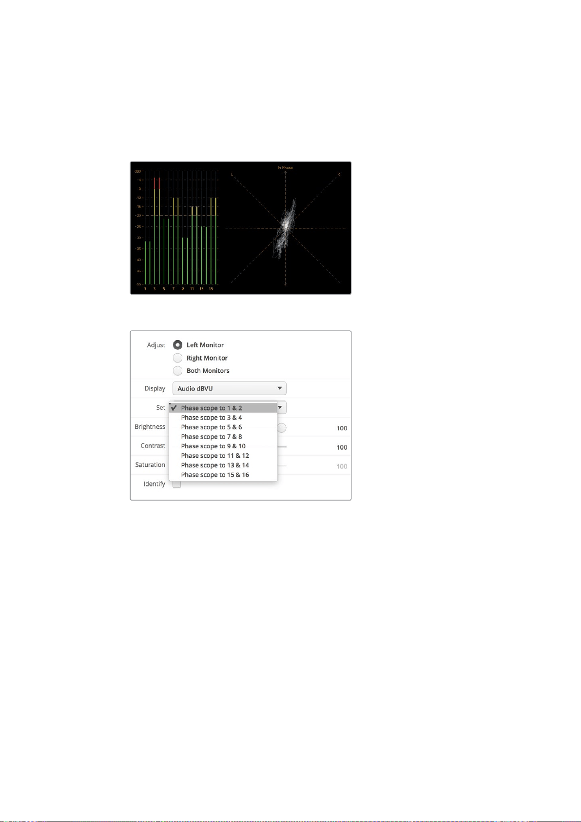
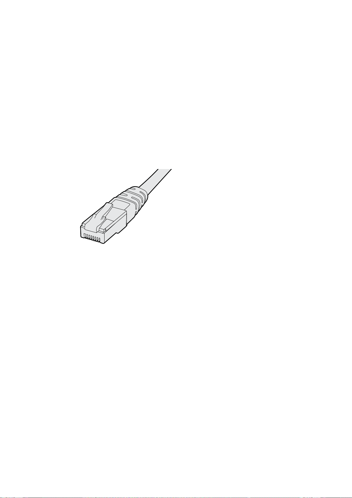
213
连接到网络
连接到网络
将
SmartView
或
SmartScope
联网后,您可以遥控调整多台设备的监视器设置。
SmartView
和
SmartScope
的监视器无需配置即可显示视频,但需要在部署之前设调整好网络设置。
网络设置只能通过
USB
接口连接计算机才能配置。
直接连接以太网
将计算机直接连接到以太网之后便可远程控制监视器配置。进行这一配置无需网络切换,因此十分
适合您进行快速安装和设置准备。如要连接更多设备,只需将各设备环通输出
Ethernet
OUT
(以太
网输出接口)以菊链式连接即可。请为联网的所有设备连接电源。
如果您想连接多台设备,但是不想使用现成的工作室网络
IP
地址,或者您没有现成的网络,只需将
它们直接连接到计算机上的以太网端口即可。这也是将
SmartView
和
SmartScope
设备连接到以太
网的最快方法,因为您不需要在网络交换机之间部署任何线缆。
以太网接头
以太网交换机
如果您想要在工作室网络上连接多台设备,那么只需将一台
SmartView
或
SmartScope
连接至网络
交换机,然后其余设备可通过开启的环通以太网输出端口相互菊链式连接,这样只需占用交换机上
的一个端口, 也无需在网络交换机上连接多条线缆了。请为所有设备连接电源,以便菊链正常运行。
连接至网络交换机的方式可让您在网络上任意一台计算机上对设备设置进行更改。如果您的网络
设 有 无 线 连 接 ,那 么 任 意 一 台
Mac
或
Windows
笔记本电脑也都可通过
WiFi
无线网络来更改设置。
按照以下步骤可将
SmartView
或
SmartScope
连接至
IP
局域网:
1 确保设备连接电源并打开设备电源开关。
2 通过标准
RJ45
以太网连接线将设备连接至网络交换机,或直接连至计算机。
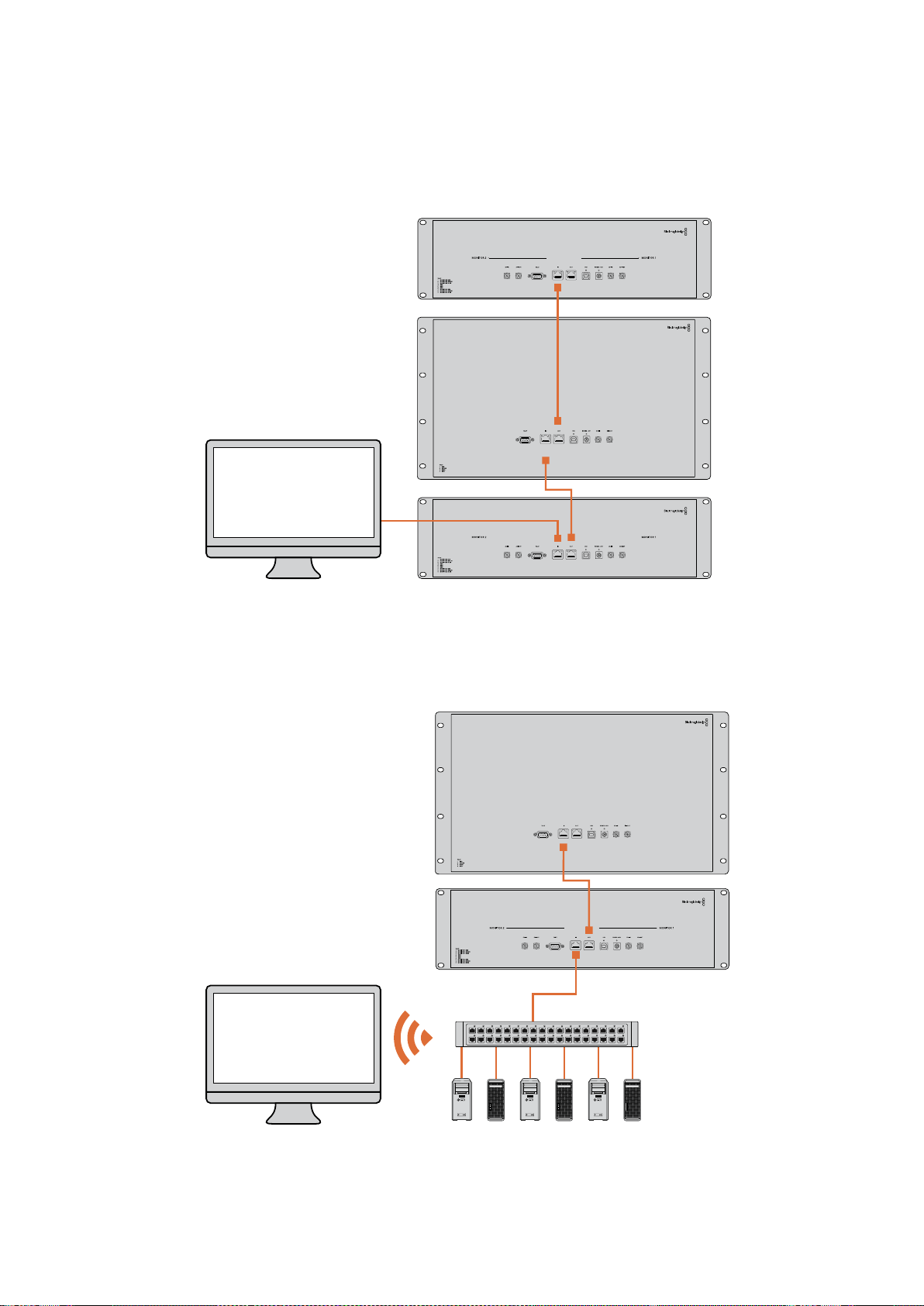

215
调整网络设置
调整网络设置
网络设置
设备名称
建议您为监视器更改名称,这样能便于区分网络中的各台
SmartView
或
SmartScope
, 例 如 :“ 现 场
摄影机
1
和
2
” 、“
Multi-View
输 出 ” 、“
4K
信 号 ”等 等 。
请确保监视器已通过以太网或
USB
连 接 ,这 样 才 能 更 改 监 视 器 名 称 。运 行
Blackmagic
SmartView
Setup
软件,并点击监视器名称下方的设置图标。在设置页面中,点击“
Network
Settings
”( 网 络 设
置 ),在“
Details
”(详细信息)部分编辑您的监视器名称。若软件检测到名称无效,您正在输入的
名称旁边将出现警告图标。若名称有效,将出现一个绿色的勾。在您的计算机键盘上按回
车键以确定名称更改。
网络设置
您的
Blackmagic
监视器必须通过
USB
连 接 至 计 算 机 ,才 能 在
Blackmagic
SmartView
Setup
中更改
网络设置。网络设置不能通过以太网连接进行更改。
默 认设 置下,
SmartView
和
SmartScope
使用
DHCP
可自动从网络中获取
IP
地址。
没有
DHCP
服 务 器 时 ,您 可 以 开 启
macOS
系 统 的“ 互 联 网 共 享 ”功 能 ,或
Windows
8.1
或
Windows
10
系 统 的“
Internet
连 接 共 享 ”(
ICS
)功能,从而为任意一台直接连接的设备提供
DHCP
地 址 。这 样 可
以避免为每台设备手动指派静态
IP
地址的步骤。您甚至可以在计算机没有网络连接的情况下,使用
此方法来为设备提供
DHCP
地 址 。请 阅 读
macOS
、
Windows
8.1
和
10
的帮助信息获取有关
网络共享的详细信息。
如配置中无法使用
DHCP
,请 使 用“
Static
IP
”( 静 态
IP
)配置其地址。请询问您的系统管理员获取一
个空余
IP
地址,从而避免网络中的
IP
地址冲突。您需要为每台
SmartView
和
SmartScope
设定一个特
有的
IP
地址,以及常用的子网掩码。除非您是有意将互联网路由器等设备连接至网络网关,否则无
需 更 改“
Gateway
”( 网 关 ) 栏 中 的 默 认 值 。
如果网络中无法找到
SmartView
或
SmartScope
监 视 器 ,可 能 是 设 备 没 有 通 过
DHCP
接收到
IP
地址,
此时您需要为每个设备手动配置合适的网络设置,步骤如下:
1 通过
USB
将
Blackmagic
SmartView
或
SmartScope
连 接 至 您 的 计 算 机 ,运 行
Blackmagic
SmartView
Setup
软件。
2 您所连接的监视器将自动显示在
SmartView
Setup
软 件 主 页 中 ,其 名 称 旁 边 将
显示一个
USB
图标。
3 调整您的监视器网络设置。
4 为其余未通过
DHCP
接收到
IP
地址的所有设备重复以上步骤。

216
调整网络设置
监视器名称旁边的
USB
图标代表了此监视器是通 过
USB
连接至您的计算机。
您的
Blackmagic
监视器需要通过
USB
连接才可调整网络设置。
网络设置可使用
DHCP
或静态
IP
地址设置,且仅可通过
USB
连接进行更改。
添加一台Blackmagic监视器
如果您已知道
SmartView
或
SmartScope
Duo
4K
的
IP
地址,但该地址未能自动显示在
Blackmagic
SmartView
Setup
软件的主页时,就需要手动添加监视器。具体操作步骤如下:
1 请确保您的
Blackmagic
监 视 器 通 过 以 太 网 连 接 。在 左 下 角 点 击“
+
”图 标 ,打 开“
Add
a
Blackmagic
Monitor
”( 添 加
Blackmagic
监 视 器 )窗 口 。
2 键入监视器的
IP
地 址 并 点 击“
Add
”( 添 加 ) 。
3 软件将验证添加设备,并将其添加到
SmartView
Setup
主页所包含的
Blackmagic
监视器
中。点击向右箭头图标可看到您最新添加的监视器。
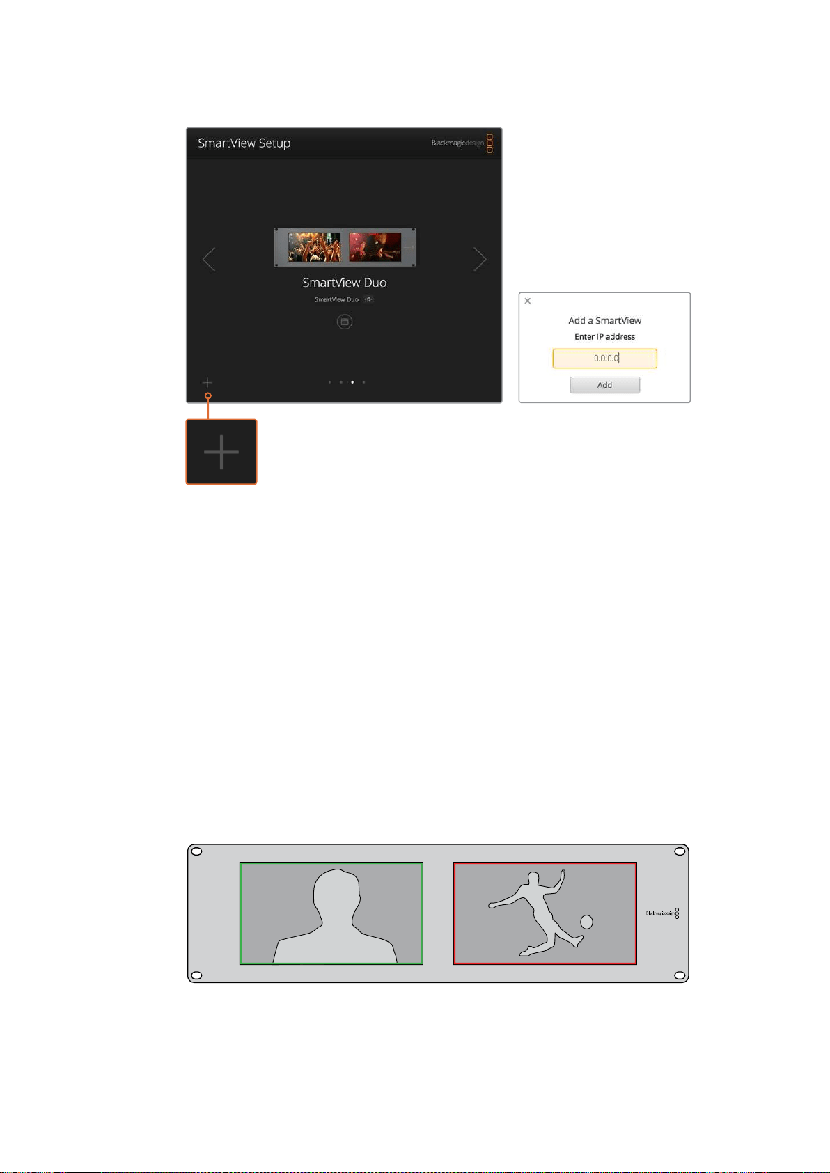
217
使用
Tally
您 可 以 点 击“
+
”图 标 并 键 入 该 监 视 器 的
IP
地 址 ,从 而 手 动 将
SmartView
或
SmartScope
监视器添加到所连接监视器列表中。
使用
Tally
Tally端口引脚连接
如果您不打算使用
Tally
功 能 ,那 就 无 需 连 接
SmartView
或
SmartScope
的
Tally
端口,因此可以跳过这
部分内容。
每台
SmartView
和
SmartScope
的监视屏都可独立显示
Tally
边框,可显示红色、绿色或是蓝色,分别
用来指示视频信号正在播出、预览或是记录的状态。
9
针
D-sub
Tally
端口允许来自切换台和自动系统的触点闭合信号。使用您的切换台或自动系统时,
请参考所附的
Tally
引脚连接图所提供的
Tally
端口配线图信息。
9
针
D
端口配线信息印于设备的后侧,提供在每个独立监视屏上显示为红色、绿色或是蓝色
Tally
边框的触点闭合信息。
显示有绿色和红色
Tally
边框的
SmartView
Duo
。
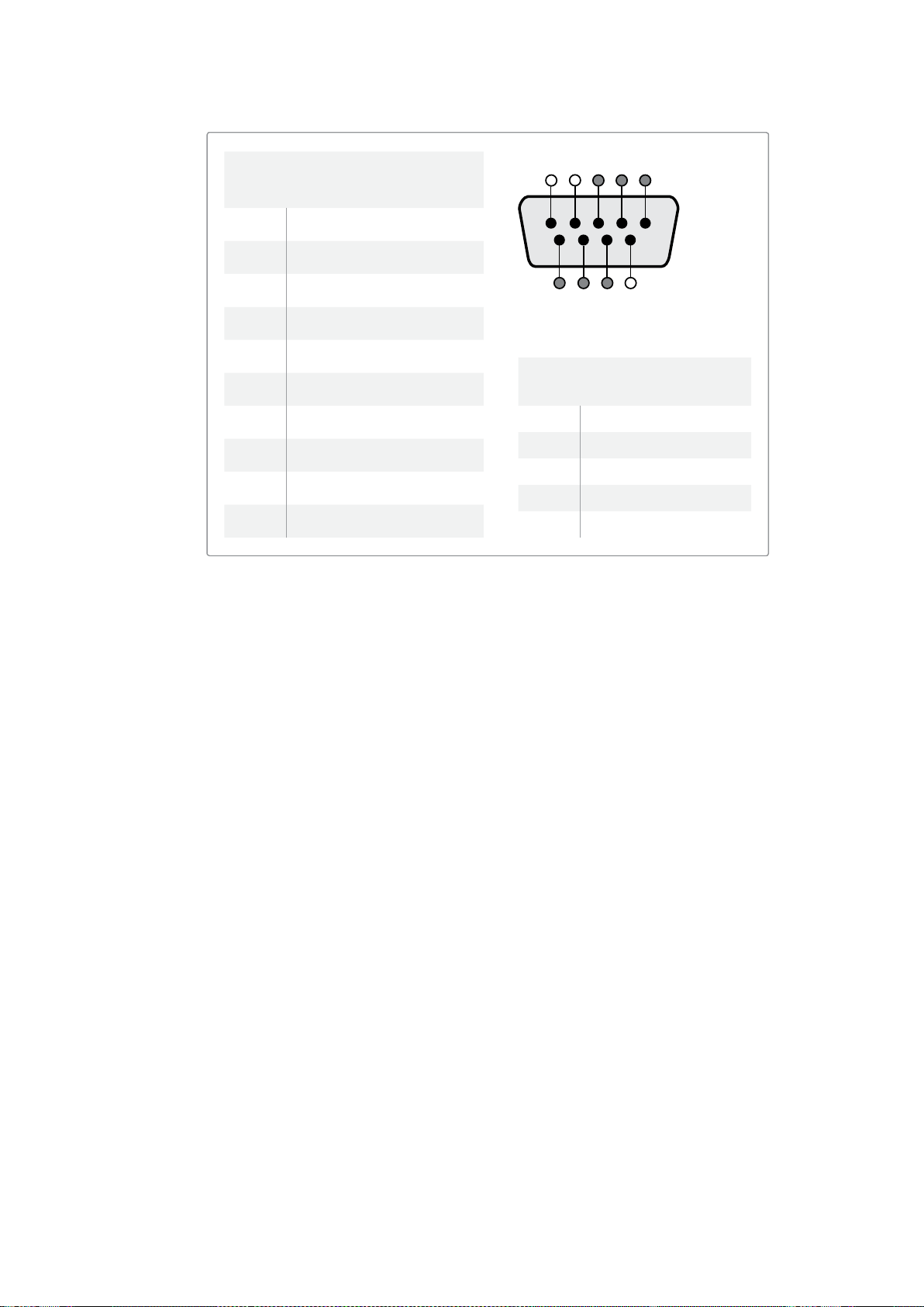
218
调整最佳监看角度
调整最佳监看角度
如果在设备机架的高处安装
SmartView
Duo
、
SmartView
HD
或是
SmartScope
监 视 器 ,那 么 您 可 能
想要反转
LCD
屏幕从而获得最佳的监看角度。当检测到屏幕翻转时,
LCD
屏幕上的图像将自动反转
到正确的角度。将设备前面板与后半部分分离并重新安装回原位,需要用到
Pozidriv
2
号 螺 丝 刀 。这
一步骤非常简单,不用打开设备后半部分的组装。
以下步骤介绍了设备如何反转安装设备,并同时让前面板上的
Blackmagic
Design
商标保持正确位
置 。此 处 需 要 用 到
Pozidriv
2
号螺丝刀。
1 卸下前面板顶部、底部、左侧以及右侧的螺丝。
SmartView
Duo
和
SmartScope
Duo
4K
设
有
10
枚螺丝,
SmartView
HD
设有
18
枚螺丝。
2 如图所示,将前面板提起,使其与后半部分离。
3 将后半部分反转。
4 将前面板安装到已反转的后半部分设备上。
5 重新将螺丝固定到机身。
您的
SmartView
或
SmartScope
已准备就绪,可以安装到机架高处了。当安装到机架后,即使有任何颠
簸,
SmartView
都可继续以最佳可视角度显示,因为没有任何可能导致出错或松动的外部旋钮或调整。
SmartView
Duo
和
SmartScope
Duo
4K
Tally
引脚连接图
引脚功能
1
监视屏
1
红色
2
监视屏
1
绿色
3
监视屏
1
蓝色
4
接地
5
接地
6
接地
7
监视屏
2
红色
8
监视屏
2
绿色
9
监视屏
2
蓝色
SmartView
HD
和
SmartView
4K
Tally
引脚连接图
引脚功能
1
红
2
绿色
3
蓝色
4
接地
5 4 3 2 1
9 8 7 6
SmartView
Tally
端口
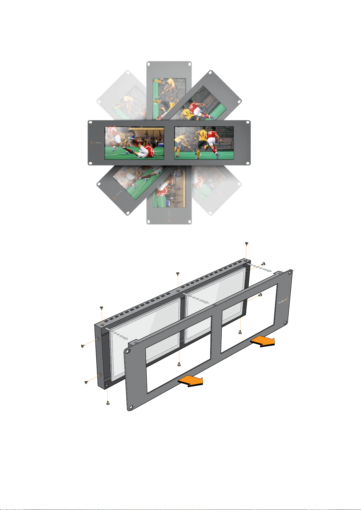

220
Developer
Information
Developer
Information
Developing
Custom
Software
Using
Blackmagic
Design
Hardware
The
Blackmagic
SmartView
Ethernet
Protocol
allows
developers
to
remotely
control
Blackmagic
SmartView
and
SmartScope
hardware
with
their
own
custom
software.
The
Blackmagic
SmartView
Ethernet
Protocol
is
a
text-based
status
and
control
protocol.
Downloading
the
Free
SmartView
Ethernet
Protocol
The
Blackmagic
SmartView
Ethernet
Protocol
is
free.
It
is
included
in
this
SmartView
&
SmartScope
manual
and
can
be
downloaded
from
www.blackmagicdesign.com/cn/support
Joining
the
Blackmagic
Design
Developer
List
The
Blackmagic
Developer
mailing
list
is
designed
for
technical
questions
regarding
technologies
used
by
Blackmagic
Design,
e.g.,
QuickTime,
Core
Media,
DirectShow,
codecs,
APIs,
SDKs,
etc.
Thefree
mailing
list
is
a
forum
where
developers
can
discuss
ideas
and
problems
with
other
developers.
Any
subscriber
may
reply
and
the
Blackmagic
Design
engineers
may
also
respond
when
appropriate.
You
can
subscribe
to
the
mailing
list
at:
http://lists.blackmagicdesign.com/
mailman/listinfo/bmd-developer
In
some
cases,
we
might
request
a
brief
outline
of
the
software
you
are
developing
if
it
is
not
immediately
obvious
from
your
domain
name
that
your
organization
develops
video
software.
Please
don
’
t
take
offence
as
we
’
re
simply
trying
to
keep
the
list
free
of
spam
and
viruses
as
well
as
end-user
customers
asking
non-development
questions,
employment
agents
or
sales
people
trying
to
promote
products
on
the
list.
The
list
is
just
for
developers.
Contacting
Blackmagic
Design
Developer
Assistance
You
can
also
contact
us
via
developer@blackmagicdesign.com
if
you
have
any
developer
related
questions
or
wish
to
ask
questions
off
the
list.
Blackmagic 2K Format
–
Overview
Blackmagic
Design
products
support
3G-SDI
video,
which
allows
twice
the
data
rate
of
traditional
HD-SDI
video.
We
thought
it
would
be
a
really
nice
idea
to
add
2K
film
support,
via
3G-SDI
technology,
so
we
could
simplify
feature
film
workflows.
With
the
popularity
of
Blackmagic
Design
editing
systems
worldwide,
now
thousands
of
people
can
benefit
from
a
feature
film
workflow
revolution.

221
Developer
Information
This
information
includes
everything
product
developers
need
to
know
for
building
native
2K
SDI
equipment.
Of
course,
all
Blackmagic
products
can
be
updated,
so
if
the
television
industry
adopts
an
alternative
SDI-based
film
standard,
we
can
add
support
for
that
too!
Frame
Structure
Transmitted
at
23.98,
24
or
25
frames
per
second
as
a
Progressive
Segmented
Frame.
Active
video
is
2048
pixels
wide
by
1556
lines
deep.
Total
lines
per
frame
:
1650
Active
words
per
line
are
1535.
One
word
consists
of
a
10-bit
sample
for
each
of
the
four
data
streams,
i.e.,
a
total
of
40
bits.
See
the
diagram
named
Blackmagic
2K
Format
-
Data
Stream
Format.
Total
active
lines
:
1556
Total
words
per
line
:
1875
for
23.98/24Hz
and
1800
for
25Hz.
Fields
per
frame
:
2,
825
lines
each
Active
lines
located
on
lines
16-793
(field
1)
and
841-1618
(field
2).
Transport
Structure
Based
on
SMPTE
372M
Dual
Link
mapping
and
SMPTE
425M-B
support
for
mapping
SMPTE
372M
into
a
single
3
Gb/s
link.
Timing
reference
signals,
line
number
and
line
CRC
insertion
is
the
same
as
above.
During
active
video,
10-bit
Red,
Green
and
Blue
data
is
sent
in
the
following
sequence:
Optional
ancillary
data
is
inserted
into
both
virtual
interfaces.
At
present,
only
audio
data
is
included:
as
per
standard
HD
audio
insertion
(SMPTE
S299M)
the
audio
data
packets
are
carried
on
data
stream
two
and
audio
control
packets
are
carried
on
data
stream
one.
Data
stream
1:
Green_1,
Green_2,
Green_3,
Green_5...Green_2047
Data
stream
2:
Blue_1,
Blue_2,
Green_4,
Blue_5...Green_2048.
Data
stream
3:
Red_1,
Blue_3,
Blue_4,
Red_5...Blue_2048.
Data
stream
4:
Red_2,
Red_3,
Red_4,
Red_6...Red_2048.
Blackmagic 2K Format
–
Vertical Timing Reference
This
diagram
shows
the
vertical
timing
details
with
line
numbers
and
Field,
Vertical
and
Horizontal
bits
for
the
Timing
Reference
Signal
codes.
Field
1 Active
F
1 0 0 0 0 0 0 0 0 0 0 0
V
1 1 1 1 1 1 0 0 0 0 1 1
LINE
#
1650 1 2 ... 14 15 16 ... 792 793 ... 825
Field
2 Active
F
0 1 1 1 1 1 1 1 1 1 1 1
V
1 1 1 1 1 1 0 0 0 0 1 1
LINE
#
825 826 827 ... 839 840 841 ... 1617 1618 ... 1650
222
Developer
Information
Blackmagic 2K Format
–
Data
Stream Format
This
diagram
shows
the
data
stream
formats
around
the
optional
ancillary
data
section
of
the
horizontal
line.
Note
that
each
active
pixel
takes
up
three
samples.
Data
Stream
1
G2041
G2042
G2043
G2045
G2046
G2047
EAV(3FFh)
EAV(000h)
EAV(000h)
EAV(XYZh)
LN0
LN1
CRC0
CRC1
ANC/Audio
Data
SAV(3FFh)
SAV(000h)
SAV(000h)
SAV(XYZh)
G1
G2
G3
G5
Data
Stream
2
B2041
B2042
G2044
B2045
B2046
G2048
EAV(3FFh)
EAV(000h)
EAV(000h)
EAV(XYZh)
LN0
LN1
CRC0
CRC1
ANC/Audio
Data
SAV(3FFh)
SAV(000h)
SAV(000h)
SAV(XYZh)
B1
B2
G4
B5
Data
Stream
3
R2041
B2043
B2044
R2045
B2047
B2048
EAV(3FFh)
EAV(000h)
EAV(000h)
EAV(XYZh)
LN0
LN1
CRC0
CRC1
040
…
040
SAV(3FFh)
SAV(000h)
SAV(000h)
SAV(XYZh)
R1
B3
B4
R5
Data
Stream
4
R2042
R2043
R2044
R2046
R2047
R2048
EAV(3FFh)
EAV(000h)
EAV(000h)
EAV(XYZh)
LN0
LN1
CRC0
CRC1
200
…
200
SAV(3FFh)
SAV(000h)
SAV(000h)
SAV(XYZh)
R2
R3
R4
R6
Word#
23.98/24
PsF
1870
1871
1872
1873
1874
1875
1
2
3
4
5
6
7
8
9
…
335
336
337
338
339
340
341
342
343
Word#
25
PsF
1795
1796
1797
1798
1799
1800
1
2
3
4
5
6
7
8
9
…
260
261
262
263
264
265
266
267
268

223
Developer
Information
Blackmagic SmartView Ethernet
Protocol v1
.
3
Summary
The
Blackmagic
SmartView
Ethernet
Protocol
is
a
text-based
status
and
control
protocol,
very
similar
in
structure
to
the
Videohub
protocol,
that
is
accessed
by
connecting
to
TCP
port
9992
on
a
SmartView
or
SmartScope
device.
Upon
connection,
the
SmartView
or
SmartScope
device
sends
a
complete
dump
of
the
state
of
the
device.
After
the
initial
dump,
state
changes
are
sent
asynchronously.
The
device
sends
information
in
blocks
which
have
an
identifying
header,
followed
by
a
colon.
Ablock
can
span
multiple
lines
and
is
terminated
by
a
blank
line.
To
be
resilient
to
future
protocol
changes,
clients
should
ignore
blocks
they
do
not
recognize,
up
to
the
trailing
blank
line.
Within
recognized
blocks,
clients
should
ignore
lines
they
do
not
recognize.
Version
1.3
of
the
Blackmagic
SmartView
Ethernet
Protocol
was
released
with
SmartView
1.3
software.
Protocol
Preamble
The
first
block
sent
by
the
SmartView
Server
is
always
the
protocol
preamble:
PROTOCOL PREAMBLE:↵
Version: 1.3 ↵
↵
The
version
field
indicates
the
protocol
version.
When
the
protocol
is
changed
in
a
compatible
way,
the
minor
version
number
will
be
updated.
If
incompatible
changes
are
made,
the
major
version
number
will
be
updated.
Device
Information
The
next
block
contains
general
information
about
the
connected
SmartView
or
SmartScope
device.
SMARTVIEW DEVICE:↵
Model: SmartView Duo↵
Hostname: stagefront.studio.example.com↵
Name: StageFront↵
M on itors: 2↵
Inverted: false↵
↵
This
example
shows
the
output
for
a
SmartView
Duo
device,
which
has
two
LCDs.
The
INVERTED
flag
indicates
whether
the
device
has
detected
that
it
has
been
mounted
in
an
inverted
configuration
to
optimize
LCD
viewing
angle.
Legend
↵ carriage return
…
and
so
on

224
Developer
Information
Network
Configuration
The
next
block
shows
the
TCP/IP
networking
configuration:
NETWORK:↵
Dynamic IP: true↵
Static ad dress: 192.168.2.2↵
Static net m ask: 255.255.255.0↵
Static g ate w ay: 192.168.2.1↵
C u r r e nt ad d r ess: 192.168.1.101↵
C u r re nt n etm a sk: 255.255.255.0↵
C u r r e nt gate wa y: 192.168.1.1↵
↵
The
network
settings
prefixed
with
CURRENT
show
the
active
TCP/IP
settings,
and
are
read-only.
The
CURRENT
settings
reflect
either
the
DHCP
or
Static
configuration,
depending
on
the
DYNAMIC
IP
flag.
Changing
Networking
Settings
The
network
can
be
configured
to
use
either
DHCP
or
a
static
configuration.
To
enable
DHCP:
NETWORK:↵
Dynamic IP: true↵
↵
To
set
a
fixed
IP
address,
supply
all
static
parameters,
thus:
NETWORK:↵
Dynamic IP: false↵
Static ad dress: 192.168.2.2↵
Static net m ask: 255.255.255.0↵
Static g ate w ay: 192.168.2.1↵
↵
The
parameters
with
the
CURRENT
prefix
are
read-only,
and
show
the
active
configuration,
regardless
of
the
static
or
dynamic
setting.
Changing
the
device
name,
or
any
network
settings,
will
cause
the
IP
connection
to
be
dropped.
The
device
will
restart
its
networking
and
advertise
its
new
name
on
the
network.
Changing
Monitor
Settings
The
display
settings
for
each
monitor
are
specified
individually.
One
or
more
parameters
can
be
modified
at
the
same
time
and
multiple
settings
can
be
supplied
in
one
block.
The
valid
range
for
numeric
values
is
0-255.
The
CONTRAST
and
SATURATION
properties
are
zero-centered,
so
the
normal
value
is
127,
such
that
the
displayed
picture
is
the
same
as
the
original.
A
value
greater
than
127
in
either
channel
will
cause
the
contrast
or
saturation
to
be
increased,
and
similarly
a
value
less
than
127
will
cause
a
decrease.
For
example,
to
set
the
brightness
to
50%
and
desaturate
the
image
to
Black
&
White:
MONITOR A:↵
Brightness: 127↵
Saturation: 0↵
↵

225
Developer
Information
Displaying
SD
in
16
:
9
The
following
command
sets
standard
definition
video
to
display
in
16:9:
MONITOR A:↵
WidescreenSD: ON↵
Displaying
SD
in
4
:
3
The
following
command
sets
standard
definition
video
to
display
in
4:3:
MONITOR A:↵
WidescreenSD: OFF↵
Identification
and
Tally
Settings
The
Identify
flag
is
transient,
and
will
cause
a
white
border
to
be
displayed
around
the
entire
picture
for
a
duration
of
15
seconds,
after
which
it
will
be
reset.
This
feature
is
primarily
aimed
at
identifying
which
monitor
is
currently
being
configured
when
it
is
mounted
in
a
rack
comprising
multiple
units.
To
turn
on:
MONITOR A:↵
Ide ntify: tr ue↵
↵
The
IDENTIFY
border
will
temporarily
override
any
other
border
setting
in
effect.
The
BORDER
property
can
be
used
to
programmatically
set
the
soft
Tally
colored
borders
to
one
of
the
primary
colors:
RED,
GREEN,
BLUE,
WHITE
or
NONE.
This
setting
can
be
overridden
by
the
electrical
Tally
signals
at
the
DB-9
input
on
the
device
itself.
For
example,
to
set
the
soft
Tally
to
green:
MONITOR B:↵
Border: green↵
↵
The
hard
wired
tally
will
always
override
the
soft
tally.
The
full
state
report
will
always
show
the
current
valid
border.
SmartScope
Settings
On
SmartScope
Duo
4K,
each
monitor
can
be
set
to
display
a
different
scope.
The
values
for
activating
specific
scopes
are
mapped
as
follows:
AudioDbfs
AudioDbvu
Histogram
ParadeRGB
ParadeYUV
Picture
(This
is
the
same
as
Video
Monitor)
Vector100
Vector75
WaveformLuma
MONITOR A:↵
ScopeMode: Picture↵
↵
In
the
example
above,
Monitor
A
has
been
set
as
a
video
monitor.

226
Developer
Information
Displaying
SD
in
16
:
9
The
set
Video
Monitor
mode
to
display
standard
definition
video
in
16:9:
MONITOR A:↵
ScopeMode: Picture↵
WidescreenSD: ON↵
Displaying
SD
in
4
:
3
To
set
Video
Monitor
mode
to
display
standard
definition
video
in
4:3:
MONITOR A:↵
ScopeMode: Picture↵
WidescreenSD: OFF↵
When
setting
one
of
SmartScope
Duo
4K
’
s
monitors
to
audio
metering,
you
can
also
select
which
channels
to
show.
The
values
for
selecting
which
audio
channels
are
mapped
in
the
following
way:
0:
Channels
1
and
2
1:
Channels
3
and
4
2:
Channels
5
and
6
3:
Channels
7
and
8
4:
Channels
9
and
10
5:
Channels
11
and
12
6:
Channels
13
and
14
7:
Channels
15
and
16
MONITOR B:↵
ScopeMode: AudioDbvu↵
AudioChannel: 0↵
↵
In
the
example
above,
Monitor
B
has
been
selected
to
display
Audio
Metering
in
Dbvu
with
audio
channels
1
and
2
selected
for
the
phase
meter.
Selecting
LUTs
for
SmartView
4K
To
select
3D
LUTs
using
SmartView
4K:
MONITOR A:↵
LUT: 0 LUT 1
1 LUT 2
NONE DISABLE
↵
↵

227
帮助
帮助
获得帮助
获得帮助的渠道有以下四种:
1 查看
Blackmagic
Design
支持中心网址
www.blackmagicdesign.com/cn/support
获得致电
Blackmagic
Design
经销商。
2 您所在地区的经销商拥有
Blackmagic
Design
的最新技术信息,并能立即为您提供帮助。
3 我们同时建议您查看经销商所提供的支持选择,因为他们可以根据您的工作流程需要
安排不同的支持计划。
4 您还可以通过
www.blackmagicdesign.com/cn/support
网 站 里 的“ 给 我 们 发 送 电 子 邮 件 ”
按钮通过电子邮件向我们询问问题。
5 致电
Blackmagic
Design
支持中心。您可以点击支持页面下方的“查找您所在地区的支持
团队”按钮,找到距离您最近的支持中心获得帮助。
请尽可能详尽描述您所遇到的技术问题和系统规格,以便我们能尽快解答您的疑问。
228
监管告知与安全信息
监管告知与安全信息
监管告知
在欧盟范围内处置电子垃圾和电子设备的注意事项。
根据产品所附的提示标志,本设备不得与其它废弃材料共同处置。处置废弃设备时,必
须交给指定收集点进行回收。对废弃设备进行单独收集并回收能够节省自然资源,且
回收方式不会损害环境和人体健康。获取更多关于废弃设备回收点的信息,请联系您
所 在 城 市 的 回 收 站 ,或 当 时 购 买 设 备 的 经 销 商 。
本 设 备 经 过 测 试 ,符 合
FCC
规则的第
15
部分对
A
类数字设备的限制。这些限制旨在为运
行于商业环境中的设备提供合理保护,使其免受有害干扰的影响。本设备可生成、使用
且辐射射频能量,如果未按照安装手册来安装和使用本设备,则可能导致对无线电通
信的有害干扰。在住宅区运行本产品可能会产生有害干扰,在这种情况下将由用户自行
承担消除干扰的费用。
必须满足以下条件后方可操作:
1 设备不会造成有害干扰。
2 设备必须能够承受任何干扰,包括可能导致意外操作的干扰。
安全信息
设备必须连接在配有保护地线的电源插座。
为了降低触电风险,请勿将设备放在会滴水或溅水的地方。
设备适合在环境温度低于
40ºC
的热带地区使用。
确保设备四周留有足够的空间,不受阻碍。
安装在机架上时,确保相邻设备不会阻碍通风。
设备内部没有操作人员可维护的零件。维修服务请联系当地
Blackmagic
Design
服务中心。
请在海平面高度为
2000
米以下的地区使用。
本 产 品 具 备 连 接 小 型 收 发 器(
SFP
)光 纤 模 块 的 功 能 。仅 使 用
Laser
Class
1
光纤
SFP
模块。
建议使用的
Blackmagic
Design
SFP
模块:
3G-SDI:
PL-4F20-311C
6G-SDI;
PL-8F10-311C
授权维修人员警告
请确保电源从插座拔出后方可进行维护。
注意
-
双极
/
中线熔断
设 备 电 源 配 有 火 线 和 中 性 线 ,适 合 连 接 挪 威 的
IT
配电系统。

229
保修
保修
12个月有限保修
Blackmagic
Design
保证本产品自购买之日起
12
个月内不会有材料和工艺上的缺陷。若本产品在保修期
内出现质量问题,
Blackmagic
Design
可选择为产品提供免费修理或更换零部件,或者更换缺陷产品。
为确保消费者有权享受本保修条款中的服务,如遇产品质量问题请务必在保修期内联系
Blackmagic
Design
并妥善安排保修事宜。消费者应将缺陷产品包装并运送到
Blackmagic
Design
的指定服务中
心进行维修,运费由消费者承担并预先支付。若消费者因任何原因退货,所有运费、保险费、关税等
各项税务以及其他费用均由消费者承担。
本保修条款不适用于任何因使用、维护不当或保养不周造成的缺陷、故障或损坏。根据本保修服
务,
Blackmagic
Design
的保修服务范围不包括以下内容:
1.
对由非
Blackmagic
Design
专门人员进
行的安装、维修或保养所造成的损坏进行维修,
2.
对因使用不当或连接到不兼容设备所造成的损
坏进行维修,
3.
对因使用了非
Blackmagic
Design
生产的零部件所导致的损坏或故障进行维修,及
4.
对经过改装或和其他产品进行组装的产品进行保养维修(因为产品经改装或组装后会增加保养
维修所需时间或保养难度)。本保修条款由
BLACKMAGIC
DESIGN
提 供 ,它 可 取 代 所 有 其 他 明 示 或
隐含的保修。
BLACKMAGIC
DESIGN
及其供应商对任何有关适销性及就特定用途的适用性等隐含
保证不作任何担保。
BLACKMAGIC
DESIGN
负责为消费者提供缺陷产品的维修或更换服务是完整
和 排 他 性 补 救 措 施 ,不 论
BLACKMAGIC
DESIGN
或其供应商是否事先获悉发生间接、特殊、偶然或
必然损坏等损坏的可能性。若消费者对本设备进行非法使用,
BLACKMAGIC
DESIGN
概 不 负 责 。对
因使用本产品造成的损失,
BLACKMAGIC
DESIGN
概不负责。本产品的操作风险由用户自行承担。
©
Copyright
2018
Blackmagic
Design
保 留 一 切 权 利 。“
Blackmagic
Design
” 、“
DeckLink
” 、“
HDLink
” 、“
Workgroup
Videohub
” 、“
Multibridge
Pro
” 、“
Multibridge
Extreme
” 、“
Intensity
”以 及“
Leading
the
creative
video
revolution
”均 为 美 国 及
其他国家的注册商标。所有其他公司名称及产品名称可能是其他所有者的注册商标。


English
환영합니다
.
모두가 고화질의 비디오를 사용할 수 있도록 하여
TV
산업을 진정한 창조 산업으로 발전시켜
나가려는 저희의 꿈에 동참할 수 있기를 희망합니다
.
비디오 모니터링은 시설 어디에서나 필요합니다
.
SmartView
4K
는 기본
4K
LCD
를 탑재해
UHD
비디오를 풀 해상도로 확인할 수 있으며
,
두께가 얇은
6RU
크기의 하우징에 컨트롤 패널까지
탑재해 설정을 신속하게 변경할 수 있습니다
.
SmartView
HD
는
6RU
크기의 랙 하우징에 놀라운
17
인치
LCD
를 탑재했으며 두께는
1
인치 미만입니다
.
SmartView
Duo
는
3RU
크기의 하우징에
완전히 독립적이고 아름다운 두 개의
8
인치
LCD
를 탑재했으며 두께는
1
인치 미만입니다
.
SmartScope
Duo
4K
는 파형 스코프 기능을 지원하는 두 개의 개별
8
인치
LCD
를 탑재해 비디오
레벨을 실시간으로 확인할 수 있습니다
.
모든
SmartView
모니터는
3G-SDI
를 통해
SD/HD/2K
비디오를 지원합니다
.
SmartScope
Duo
4K
와
SmartView
4K
는 각각
6G-SDI
및
12G-SDI
를 통해
UHD
4K
또한 지원합니다
.
비디오 모니터링은 구입하자마자 바로 사용할 수 있으며
,
사용이 쉽고 직관적인 환경 설정
도구인
Blackmagic
SmartView
설치 소프트웨어까지 제공됩니다
.
본 사용 설명서는
SmartView
또는
SmartScope
의 설치와 관련된 모든 정보를 담고 있지만
,
IP
주소나 컴퓨터 네트워크에 대한 지식이 부족할 경우에는 기술 지원을 요청하는 것이 좋습니다
.
SmartView
와
SmartScope
는 설치가 간단하지만 설치를 마친 후에 몇 가지 기술적 설정 사항을
적용해야 할 수도 있습니다
.
설치가 완료되기까지는 약
5
분 정도의 시간이 소요됩니다
.
저희 웹사이트
(www.blackmagicdesign.com/kr)
에 방문하여 고객 지원 페이지에서 최신 버전의 설명서와
SmartView
소프트웨어를 다운로드하세요
.
소프트웨어를 다운로드할 때 사용자 정보를
등록하시면
,
새로운 소프트웨어가 출시될 때마다 업데이트 소식을 받아보실 수 있습니다
.
저희는
새로운 기능과 제품 개선을 위해서 끊임없이 노력하고 있으며 항상 고객 여러분의 의견을
기다립니다
!
Blackmagic
Design
의
CEO
그랜트 패티

목차
SmartView
&
SmartScope
시작하기 233
SmartView
및
SmartScope
소개
233
비디오 소스 연결하기
234
컴퓨터에 연결하기
234
Blackmagic
SmartView
Setup
소프트웨어 설치하기
235
Blackmagic
SmartView
Setup
소프트웨어 사용하기
236
소프트웨어 업데이트
236
모니터 설정 조정하기
236
SmartView
4K
사용하기
238
Blackmagic
SmartView
4K
소개
239
컨트롤 패널 버튼
240
Blackmagic
SmartView
Setup
을 사용해
3D
LUT
로딩하기
242
SmartScope
Duo
4K
사용하기
243
Blackmagic
SmartScope
이란
?
243
비디오 모니터링
(Video
Monitoring)
디스플레이
243
파형
(Waveform)
디스플레이
244
벡터 스코프
(Vectorscope)
디스플레이
245
퍼레이드
(Parade)
디스플레이
247
히스토그램
(Histogram)
디스플레이
248
오디오 미터링 표시
249
네트워크에 연결하기 250
다이렉트 이더넷
250
이더넷 네트워크 스위치
251
네트워크 설정 조정하기 253
네트워크 설정
253
Blackmagic
모니터 추가하기
254
탈리 사용 255
탈리 포트 핀 연결
255
시야각 최적화하기 256
Blackmagic
2K
Format
–
Overview
258
Blackmagic
2K
Format
–
Vertical
Timing
Reference
259
Blackmagic
2K
Format
–
Data
Stream
Format
260
Blackmagic
SmartView
Ethernet
Protocol
v1.3
261
지원 265
지원 받기
265
규제 사항 및 안전 정보 266
보증 267

시작하기
SmartView
및
SmartScope
소개
SmartView
모니터는 랙 기반의 모니터링을 필요로 하는 모든 시설에서 사용하기에 완벽합니다
.
전원을 연결하여
SDI
소스를 연결해주기만 하면 곧바로 사용할 수 있습니다
.
SmartView
4K
는
15.6
인치
4K
LCD
를 탑재해
SD,
HD,
UHD
비디오를 원본
3840x2160
픽셀 해상도로
모니터링할 수 있습니다
.
전면 컨트롤 패널 버튼을 통해 입력 선택과 화면 밝기 조정
,
블루 채널
노이즈 확인
,
블랭킹 정보 보기
,
3D
LUT
적용 등의 작업을 수월하게 진행할 수 있습니다
.
SmartView
HD
는
17
인치
HD
LCD
모니터를 탑재해 풀 해상도의
HD
영상을 자신감 있게
모니터링할 수 있습니다
.
SmartView
Duo
는 서로 다른 비디오 신호를 동시에 디스플레이할 수 있는 두 개의 모니터를
탑재했습니다
.
예를 들어
,
한 모니터에서
RGB
4:4:4
를 수신하는 동안 다른 모니터에서
YUV
4:2:2
신호를 디스플레이할 수 있습니다
.
두 모니터에서 각각
NTSC
와
PAL
신호를 디스플레이할 수
있습니다
.
여러 가지 조합이 가능하지만 이들 모두 싱글
SDI
케이블을 각 모니터에 연결하는
것만큼이나 간단합니다
.
SmartScope
Duo
4K
는
SmartView
Duo
의 모든 기능을 지원할 뿐 아니라 파형
,
벡터 스코프
,
인기
스코프를 디스플레이하여 비디오 및 오디오 레벨을 실시간으로 모니터링할 수 있습니다
.
여기에
UHD
4K
까지 완벽하게 지원합니다
!
SmartView
및
SmartScope
모니터의 모든
SDI
입력 연결은
2K
비디오를 포함한
SD,
HD,
3G-SDI
자동 감지 기능을 지원합니다
.
SmartView
4K
에서는
12G-SDI
를 통해
2160p60
등의
UHD
포맷 또한
감지합니다
.
SmartScope
Duo
4K
에서는
6G-SDI
를 통해
UHD
4K
비디오를 자동으로 감지합니다
.
한 대의 컴퓨터에서 여러 대의
SmartView
및
SmartScope
유닛의 설정을 원격으로 조절하려면
이들 모두 이더넷을 통해 연결하세요
.
다시 말해
,
설정을 변경할 때마다 컴퓨터 연결용
USB
케이블을
들고 각 유닛 사이를 돌아다닐 필요가 없습니다
.
이제 사용 준비가 모두 완료되었습니다
!
본 사용 설명서를 계속 읽으면서
SmartView
및
SmartScope
연결과
Blackmagic
SmartView
설치 프로그램에서의 모니터 설정 환경 설정
,
네트워크 연결에 관한
자세한 정보를 확인하세요
.
SmartView
4K SmartView
HD
SmartView
Duo SmartScope
Duo
4K
233
시작하기
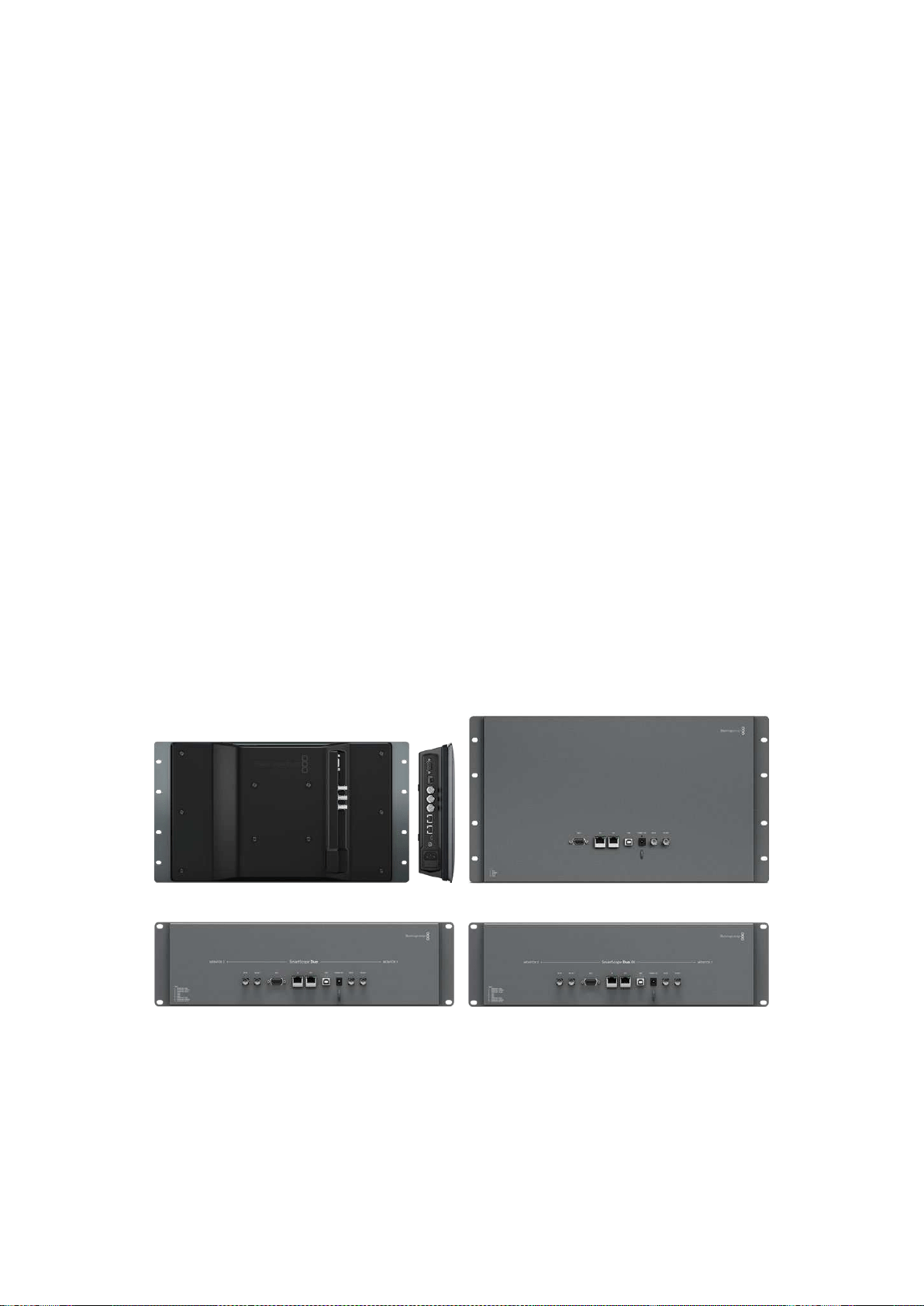
비디오 소스 연결하기
SmartView
및
SmartScope
모니터는 일반
BNC
커넥터를 탑재해 스위처
,
카메라
,
캡처 카드
,
데크
,
디스크 레코더 등의
SDI
장비를 연결할 수 있습니다
.
살펴보기
비디오를 쉽게 디스플레이할 수 있습니다
!
유닛 전원을 켜고 비디오 소스를
SDI
입력에 연결하기만
하면 됩니다
.
전원을 연결해 소스를 연결하고 나면 비디오가 나오는 것을 바로 확인할 수 있습니다
.
SD,
HD,
2K
신호는
SDI
입력 및 루프스루 출력 연결을 통해 자동 감지됩니다
.
SmartView
4K
와
SmartScope
Duo
4K
에서는
UHD
4K
까지 감지합니다
.
유닛에 비디오가 전송되지 않으면 유효 신호가 전송될 때까지 전원을 절약하기 위해 배면광에 불이
들어오지 않습니다
.
데이지 체이닝 모니터
각
SmartView
및
SmartScope
모니터에는 루프스루 출력뿐 아니라 개별
SDI
입력이 탑재되어 있어
여러 대의 모니터를 함께 연결해 동일한 입력 신호를 디스플레이할 수 있습니다
.
첫 번째 유닛의 전원을 켜세요
.
비디오 소스 신호를
SDI
입력에 연결하세요
.
비디오가
화면에 바로 나타납니다
.
두 번째 유닛의 전원을 켜세요
.
SDI
케이블을 사용해 첫 번째 유닛의 루프스루 출력과 두 번째
유닛의
SDI
입력을 연결하세요
.
원하는 유닛을 무제한으로 체인 연결할 수 있습니다
.
SmartScope
Duo
4K
를 사용해 파형을 모니터링하는 경우 모니터
1
출력을 모니터
2
로 루프 출력해
두 디스플레이 모두 동일한 입력 신호를 사용하게 할 수도 있습니다
.
비디오가 디스플레이되면
Blackmagic
SmartView
설치 프로그램을 사용해
SmartScope
Duo
4K
의
모니터 설정을 조정하거나 스코프를 선택할 수 있으며
,
Blackmagic
SmartView
4K
에
3D
LUT
을
로딩할 수도 있습니다
.
SmartView
4K SmartView
HD
SmartView
Duo SmartScope
Duo
4K
컴퓨터에 연결하기
USB
를 통해 컴퓨터와
SmartView
또는
SmartScope
를 연결한 뒤
,
Blackmagic
SmartView
Setup
소프트웨어를 설치해 모니터 설정을 조정할 수 있습니다
.
USB
연결을 통해
Blackmagic
Design
웹사이트에서 다운로드한 내부 소프트웨어를 업데이트할
수도 있습니다
.
소프트웨어 업데이트는 새로운 기능과 새로운 하드웨어 호환성
,
새로운 포맷 지원
기능 등을 제공합니다
.
Blackmagic
SmartView
Setup
소프트웨어는
macOS
와
Windows
를
모두 지원합니다
.
234
시작하기
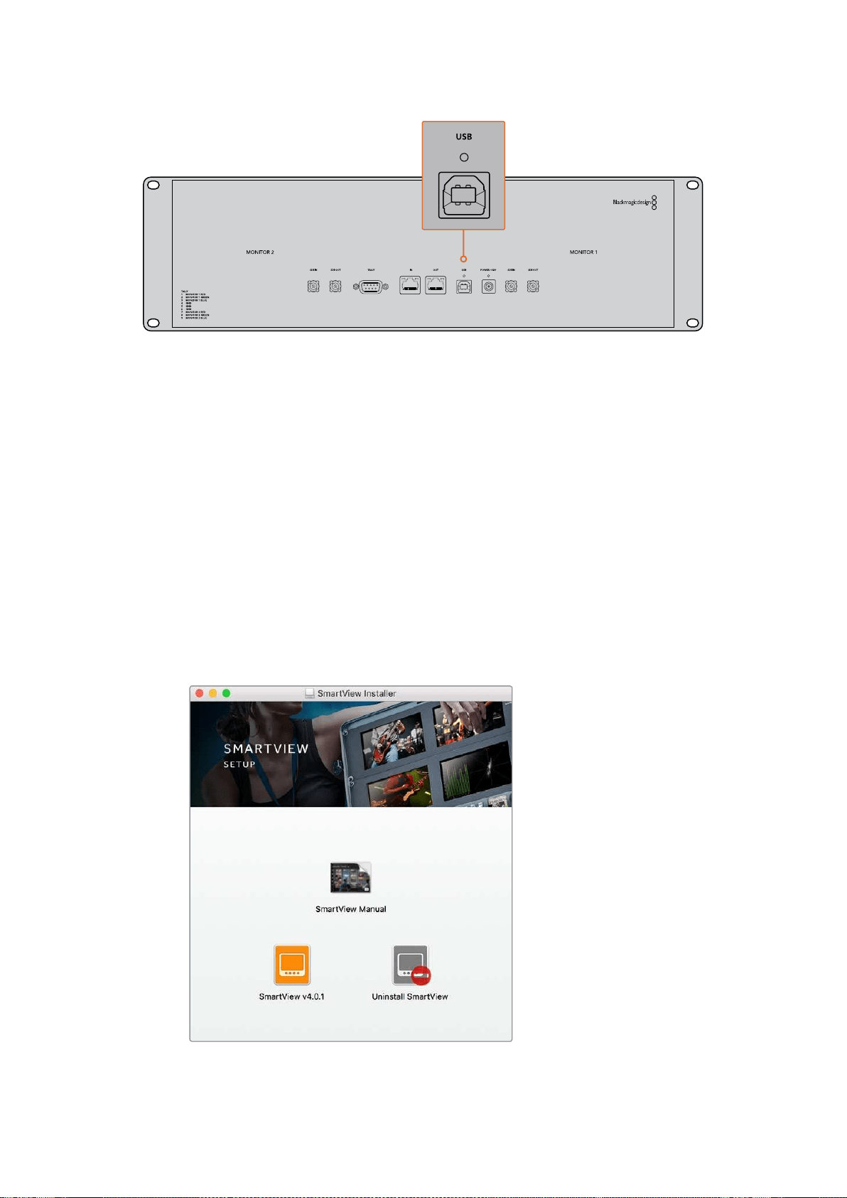
Blackmagic
SmartView
Setup
소프트웨어 설치하기
Blackmagic
SmartView
Setup
소프트웨어는
macOS
최신 버전인
Sierra
및
High
Sierra
와
,
최신
서비스 팩이 설치된
64
비트 버전의
Windows
8.1/10
에서 운용됩니다
.
원할 경우
,
Blackmagic
SmartView
Setup
소프트웨어를 네트워크에 연결된 여러 대의 컴퓨터에 설치할 수 있습니다
.
SmartView
와 함께 제공되는
SD
카드에 소프트웨어 설치자가 포함되어 있지만
www.blackmagicdesign.com/kr/support
에서 최신 버전의 소프트웨어를 다운받는 것이 좋습니다
.
macOS
에 설치하는 방법
제품에 포함된
SD
카드나 다운로드한 디스크 이미지를 열고
,
Install
SmartView
아이콘을 더블
클릭하세요
.
응 용 프 로 그램 폴더에
SmartView
폴더가 생성되며
,
여기엔
SmartView
Setup
소프트웨어와
기존 버전 제거 프로그램
,
본 사용 설명서 및 기타
SmartView
정보가 담긴
Documents
폴더가
포함되어 있습니다
.
Windows
에 설치하는 방법
Windows
에서 제품에 포함된
SD
카드나 다운로드한 압축 파일을 열고
,
Install
SmartView
설치
프로그램을 더블 클릭하세요
.
화면에 나타나는 지시 사항에 따라 소프트웨어를 설치하세요
.
macOS
에 설치하려면 제품과 함께 제공된
SD
카드나 다운로드 폴더에 있는
SmartView.dmg
파일을 실행한 뒤
,
Install
SmartView
아이콘을 더블 클릭하세요
.
235
시작하기
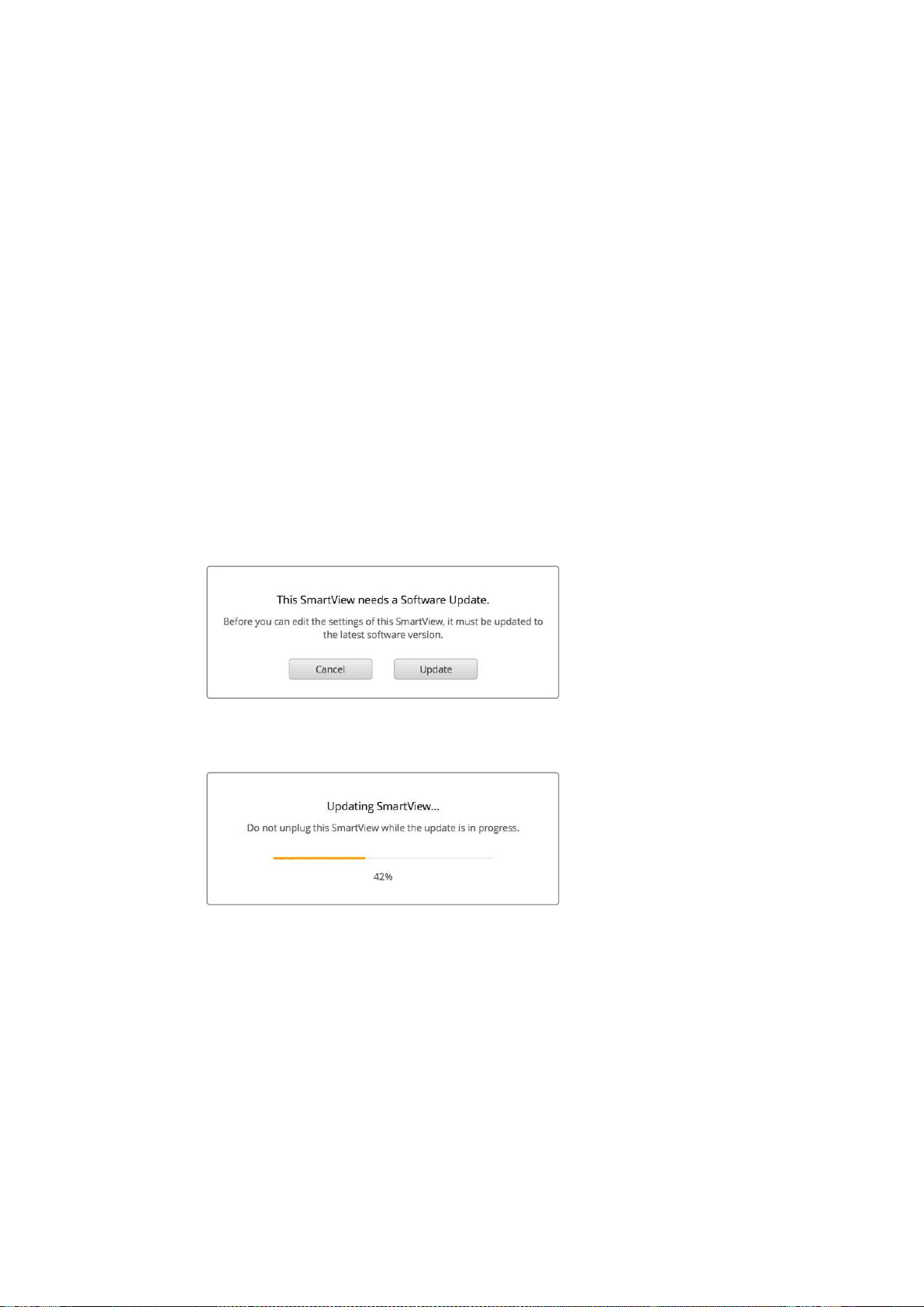
Blackmagic
SmartView
Setup
소프트웨어 사용하기
소프트웨어 업데이트
Blakmagic
SmartView
Setup
소프트웨어를 설치 및 실행한 뒤
,
현재 연결된 모니터 이름 아래쪽에
있는 설정 아이콘을 클릭하세요
.
SmartView
또는
SmartScope
의 내부 소프트웨어를 업데이트하라는
메시지가 나타납니다
.
다음 순서에 따라 업데이트를 진행하세요
.
1
USB
나 이더넷을 통해
SmartView
또는
SmartScope
를 컴퓨터와 연결한 뒤
,
Blackmagic
SmartView
Setup
소프트웨어를 실행하세요
.
2
메시지 창이 나타나면 간단히
Update
를 클릭하세요
.
업데이트가 완료되기까지
5
분 정도 소요됩니다
.
3 업데이트가 완료되면
[This
SmartView
has
been
updated]
라는 메시지가 나타납니다
.
4
[Close]
버튼을 누르세요
.
내부 소프트웨어를 업데이트할 필요가 없는 경우
Blackmagic
SmartView
Setup
소프트웨어에서
모니터 설정 페이지가 열립니다
.
SmartView
Setup
소프트웨어를 실행한 뒤 연결된
SmartView
또는
SmartScope
의 설정 아이콘을 열었을 때
,
내부 소프트웨어
업데이트가 필요하면 해당 메시지가 나타납니다
.
업데이트가 완료되기까지
5
분 정도 소요됩니다
.
모니터 설정 조정하기
Blackmagic
SmartView
Setup
소프트웨어를 실행하면
USB
나 이더넷을 통해 연결된 모든
SmartView
또는
SmartScope
를 즉각 검색한 뒤
,
해당 유닛을
SmartView
Setup
홈페이지에 나타냅니다
.
네트워크에 연결된
Blackmagic
모니터가 한 대 이상일 경우 홈페이지 양쪽에 있는 좌
/
우 화살표
아이콘을 사용해 조정하고자 하는 모니터를 선택하세요
.
USB
를 통해
Blackmagic
모니터를 연결한
경우
,
모니터 이름 옆에
USB
아이콘이 나타납니다
.
236Blackmagic
SmartView
Setup
소프트웨어 사용하기
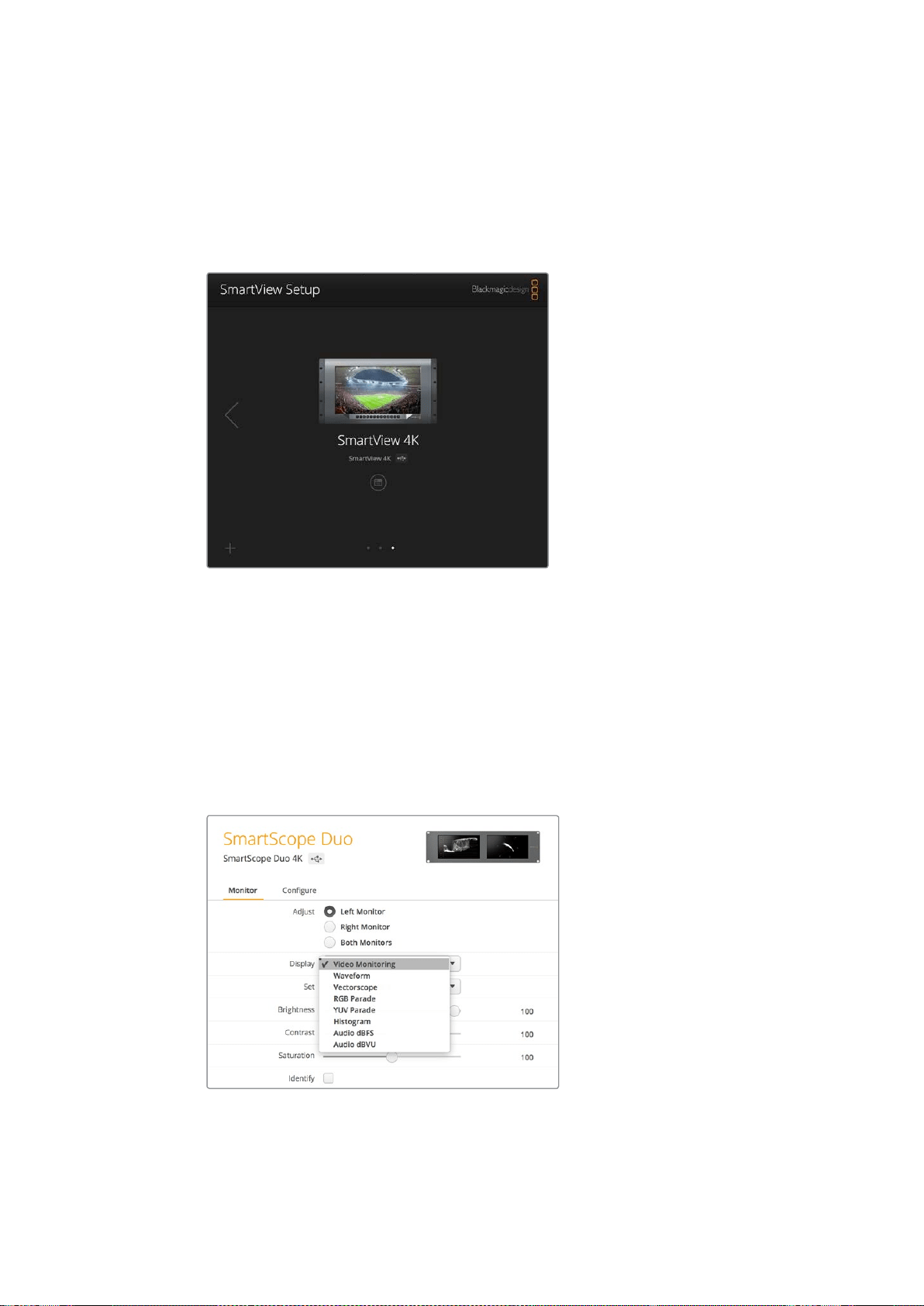
설정을 조정하려면 이더넷 또는
USB
를 통해 연결된 모니터를 선택한 뒤
,
해당 모니터 이름 아래
있는 설정 아이콘을 클릭하세요
.
그러면 선택한 모니터의 설정 페이지가 열립니다
.
원하는 설정으로
변경했다면
Save
버튼을 눌러 설정을 저장하고
SmartView
Setup
시작 화면으로 돌아가세요
.
Blackmagic
모니터에서 사용 가능한 설정과 이를 적용하는 방법에 대한 정보는 다음 섹션에서
확인하실 수 있습니다
.
Blackmagic
SmartView
Setup
소프트웨어를 사용해 네트워크 설정을
조정하는 방법에 대한 자세한 정보는
[
네트워크 연결 조정하기
]
부분을 참고하세요
.
Blackmagic
SmartView
Setup
소프트웨어에서는
USB
또는
네트워크를 통해 연결된 모든
SmartView
및
SmartScope
유닛을
자동으로 검색합니다
.
모니터의 내부 소프트웨어 업데이트 시
모니터가
USB
또는 이더넷을 통해 연결되어 있는지 반드시
확인하세요
.
모니터 이름 옆에
USB
아이콘이 나타납니다
.
모니터 설정
각 모니터의 설정 및 디스플레이 조정은 모니터가
USB
또는 이더넷을 통해 연결되어 있는 경우에만
가능합니다
.
SmartView
Setup
홈페이지에 있는 좌
/
우 화살표 아이콘을 사용해 설정하고자 하는
모니터를 선택한 다음 모니터 이름 옆에 아래에 있는 설정 아이콘을 클릭하세요
.
이 설정 페이지는
선택한
Blackmagic
모니터에서 지원하는 기능에 맞게 자동으로 커스터마이즈됩니다
.
SmartScope
의 경우
,
Display
드롭다운 메뉴에서 스코프 또는
비디오 모니터링 중 원하는 것을 선택할 수 있습니다
.
237Blackmagic
SmartView
Setup
소프트웨어 사용하기
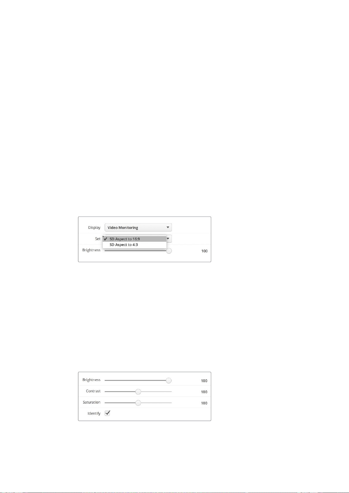
조정
(Adjust)
SmartScope
또는
SmartView
Duo
를 사용할 경우
,
Left
Monitor/Right
Monitor/Both
Monitors
중
하나를 골라 조정하고자 하는 모니터를 선택하세요
.
두 모니터를 동시에 조정할 수도 있습니다
.
Both
Monitors
를 선택한 다음 밝기
/
콘트라스트
/
채도를 변경할 경우
,
해당 변경 사항이
SmartView
Duo
및
SmartScope
의 양쪽 모니터에 적용됩니다
.
디스플레이
(Display)
SmartScope
를 사용할 경우
,
Display
드롭다운 메뉴에 선택 가능한 스코프 옵션이 나타납니다
.
비디오 이미지를 확인하고자 할 경우엔
Video
Monitoring
을 선택하세요
.
설정
(Set)
SmartScope
에서
SD
비디오를 사용할 경우
,
Set
드롭다운 메뉴를 통해 비디오 모니터링 디스플레이를
위한
4:3
또는
16:9
종횡비를 선택할 수 있습니다
.
Set
드롭다운 메뉴에서는 선택한 디스플레이를
위한 벡터 스코프
,
오디오
dBFS,
오디오
dBVU
등의 추가 옵션을 제공합니다
.
Video Monitoring: 비디오 이미지를
4:3
또는
16:9
종횡비 보기로 선택할 수 있습니다
.
와이드스크린 애너모픽
SD
비디오를 모니터링할 경우
,
16:9
종횡비를 선택하세요
.
기존의
4:3
SD
비디오를 모니터링할 경우
,
4:3
종횡비를 선택하세요
.
Vectorscope: 입력을 기반으로
100%
또는
75%
컬러바 테스트 신호를 선택하세요
.
Audio dBFS: 위상 모니터링에 사용할 오디오 채널을 선택하세요
.
Audio dBVU: 위상 모니터링에 사용할 오디오 채널을 선택하세요
.
애너모픽
SD
비디오를 모니터링할 경우
,
[SD
Aspect
to
16:9]
로 설정하세요
.
밝기
,
콘트라스트
,
채도
(Brightness,
Contrast,
Saturation)
슬라이더를 조절해 밝기
,
콘트라스트
,
채도 설정을 적용하세요
.
모니터 테두리 표시
Identify
확인란을 활성화하면
Blackmagic
SmartView
Setup
에서 선택한 모든 모니터에 흰색
테두리가 나타납니다
.
네트워크를 통해 여러 대의
SmartView
및
SmartScope
유닛을 연결한 경우
이 설정을 통해 선택된 모니터를 쉽게 식별할 수 있습니다
.
이 설정을
Both
Monitors
설정과 함께 사용할 경우
SmartView
Duo
또는
SmartScope
Duo
4K
의
모든 모니터에 흰색 테두리가 나타납니다
.
슬라이더를 좌
/
우로 드래그하여 대비
,
채도 설정을 조절합니다
.
선택한
모니터를 시각적으로 확인하려면
Identify
설정을 확인하세요
.
SmartView
4K
사용하기
238SmartView
4K
사용하기
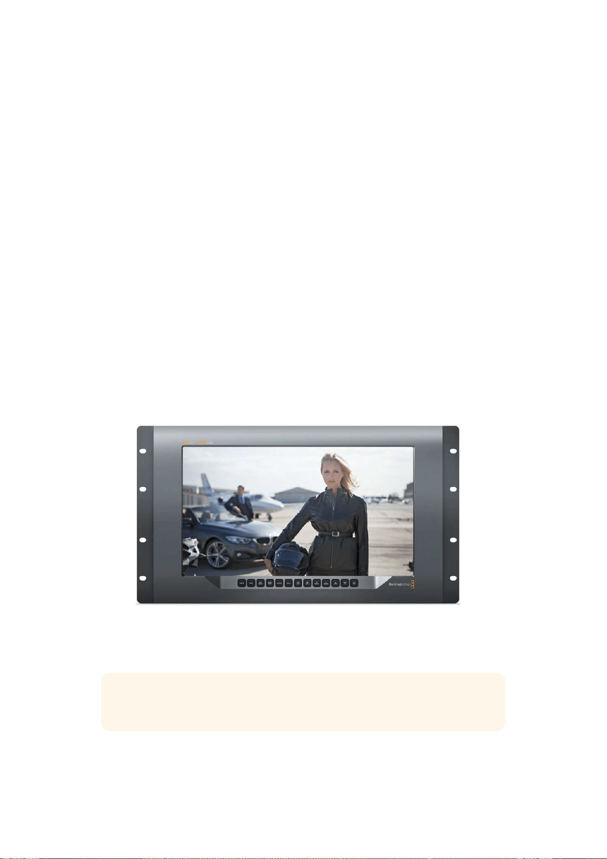
Blackmagic
SmartView
4K
소개
SmartView
4K
는
6RU
크기의
UHD
12G-SDI
방송용 모니터로
SD,
HD,
그리고 최대
2160p60
의
원본
UHD
비디오를 디스플레이합니다
.
밝은 디스플레이와 넓은 시야각을 제공하는
SmartView
4K
는
정확한 초점 및 색상 모니터링을 위해 크리스탈처럼 선명한 영상을 지원하며 거의 모든 비디오
포맷을 지원합니다
.
스튜디오 및 야외 방송 환경을 위해 제작된
SmartView
4K
는 사용법이 굉장히 간단합니다
.
측면에
탑재된 커넥터와
VESA
지원 기능을 통해 협소한 공간뿐 아니라 벽이나 연접식 암에 설치할 수
있습니다
.
SmartView
4K
는 내장 컨트롤 패널에서 운영할 수 있으며 전면 패널에 접근이 불가능한
경우 이더넷 연결을 통해 원격으로 제어할 수 있습니다
.
두 개의 멀티 레이트
12G-SDI
입력을 통해 두
SDI
소스 및
SMPTE
호환
SFP
모듈 소켓 중에서
선택할 수 있어
,
광섬유
SDI
모듈 추가 시 광섬유로 비디오를 연결할 수 있습니다
.
12G-SDI
출력을
제공해 비디오 피드를 다른 장비에 전송할 수 있을 뿐 아니라 네트워크
,
원격 제어
,
루프 출력을
위한 두 개의 이더넷 커넥터를 통해 다른 모니터와 데이지 체인 방식으로 연결할 수 있습니다
.
다른
커넥터로는 라이브 프로덕션용 탈리 입력과 내부 소프트웨어 업데이트용
USB
포트가 있습니다
.
Blackmagic
SmartView
Setup
소프트웨어를 사용해
.cube
확장자 형식의 표준
3D
LUT
이나
DaVinci
Resolve
에서 생성한
LUT
을 로딩할 수도 있습니다
.
3D
LUT
을 사용해
SmartView
4K
를 카메라에
직접 연결하면 최종 그레이딩 작업 결과물에 최대한 가까운 클립 영상을 확인할 수 있습니다
.
2
단계의 포커스 피킹을 통해 숏의 포커스가 정확한지 확인할 수 있으며
,
AC/DC
전원 옵션을 지원해
SmartView
4K
를 주전원에 연결해 사용하거나 야외 촬영 현장에서의 휴대성을 위해 외부 배터리에
연결할 수 있습니다
.
SmartView
4K
는 휴대용 및 스튜디오 방송용 프로덕션 디스플레이를 위한 완벽한 모니터링
솔루션으로
,
비디오 영상을
SD/HD/UHD
비디오를 원본
3840x2160
픽셀 해상도로
모니터링할 수 있습니다
.
참고
DC
전원 입력을 통해 외부 전원을 연결할 경우 외부 전원이
12V
의
24
와트 전력
공급을 지원하는지 확인하세요
.
239SmartView
4K
사용하기
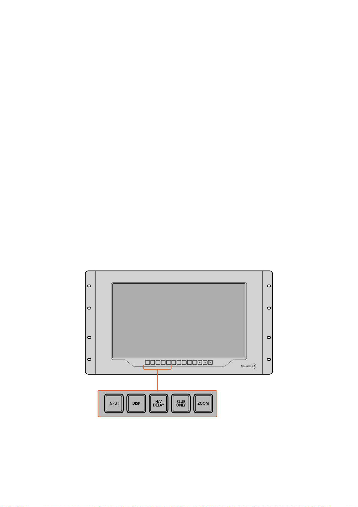
컨트롤 패널 버튼
SmartView
4K
컨트롤 패널에는 여러개의 버튼이 탑재되어 있어 설정을 신속하게 변경 할 수 있습니다
.
INPUT
이 버튼을 눌러
SmartView
4K
의 두
12G-SDI
입력에 연결된 비디오 신호와 광섬유
SFP
모듈 입력
간을 이동할 수 있습니다
.
입력에 연결된 비디오가 없을 경우 해당 입력이
SmartView
4K
에서 검은
화면으로 나타납니다
.
입력 간을 전환할 경우 연결된 입력의 포맷에 대한 정보가 모니터 좌측 하단에
잠시 동안 표시됩니다
.
DISP
DISP
버튼을 사용해
SmartView
4K
의
LCD
밝기를 조정할 수 있습니다
.
위
/
아래 화살표 버튼을
사용해 밝기를 조정하세요
.
DISP
버튼을 다시 누르면 설정 창이 사라집니다
.
H/V
DELAY
H/V
DELAY
버튼을 눌러
SDI
비디오 신호에 임베드된 보조 데이터를 신속하게 확인할 수 있습니다
.
예를 들어
,
H/V
DELAY
버튼을 한 번 누르면 수평 보조 데이터를 확인할 수 있습니다
.
H/V
DELAY
버튼을 다시 한 번 누르면 폐쇄 자막과 같은 데이터에 자주 사용되는 수직 보조 데이터를
확인할 수 있습니다
.
BLUE
ONLY
디지털 비디오 신호에서 발생하는 노이즈의 대부분은 블루 채널 내에서 발생합니다
..
BLUE
ON LY
버튼을 누르면 블루 채널의 노이즈를 쉽게 검사할 수 있습니다
.
그러면 블루 채널 정보만 흑백으로
나타납니다
.
흑백 이미지는 카메라 초점을 확인할 시에도 사용할 수 있습니다
.
ZOOM
ZOOM
버튼을 사용하면 선명한 카메라 초점을 얻을 수 있습니다
.
이 버튼을 한 번 누르면 영상이
확대됩니다
.
이제 피사체의 초점이 잘 맞는지 제대로 확인할 수 있습니다
.
ZOOM
버튼을 다시 누르면
일반 크기로 되돌아갑니다
.
INPUT DISP
H/V
DELAY
3D
LUT 1
BLUE
ONLY
ZOOM PEAK
3D
LUT 2
H
MARK
V
MARK
240SmartView
4K
사용하기
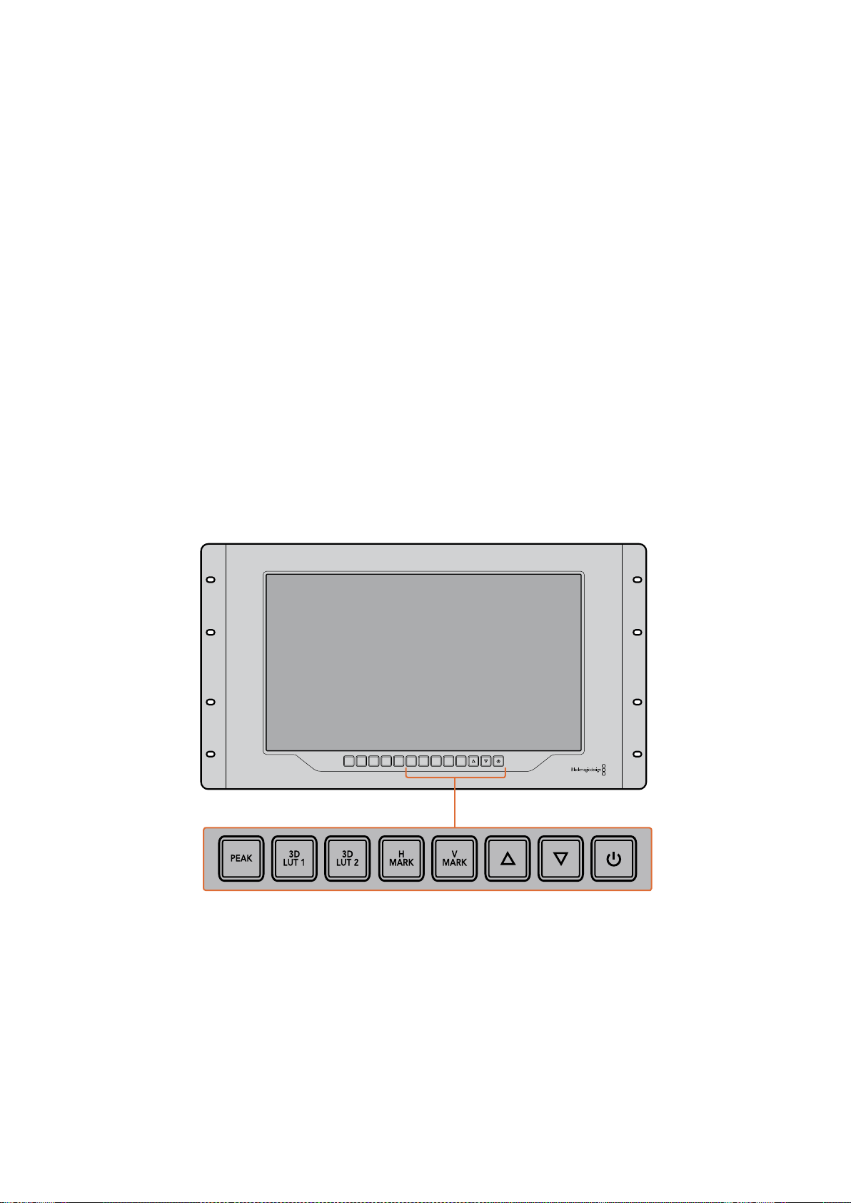
PEAK
PEAK
버튼을 눌러 포커스 피킹을 활성화하면 카메라 초점을 쉽게 확인할 수 있습니다
.
이 경우
영상 속 가장 선명한 부분의 주변에 밝은 초록색 테두리가 나타납니다
.
PEAK
버튼을 연속해서
누르면 피킹 강도를
2
단계로 조절해가며 사용할 수 있습니다
.
초록색 테두리가 뚜렷하게 나타나는
것은 카메라 초점이 잘 맞춰져 있음을 뜻합니다
.
3D
LUT
1
및
3D
LUT
2
LUT
버튼을 사용하면
Blackmagic
DaVinci
Resolve
또는 업계 표준
.cube
LUT
에서 생성된 커스텀
3D
LUT
이미지를 확인할 수 있습니다
.
LUT
을 활성화하려면
LUT
버튼을 한 번 누르세요
.
버튼을
다시 한 번 누르면
LUT
이 비활성화됩니다
.
SmartView
4K
에서
3D
LUT
을 사용하는 방법에 대한
자세한 정보는
[Blackmagic
SmartView
Setup
을 사용해
3D
LUT
로딩하기
]
섹션을 참고하세요
.
H
Mark
및
V
Mark
H
Mark
및
V
Mark
버튼을 사용해 프레임 마커를 확인 및 편집할 수 있습니다
.
프레임 마커를 통해
숏을 합성하거나 화면 안전 영역 내의 주요 정보 또는 그래픽을 보존할 수 있습니다
.
TV
모델에
따라 비디오 신호의 가장자리가 조금씩 나타나기도 하기 때문에 간편하게안전 영역을 확인할 수
있습니다
.
화면의 안전 영역은 영상 확인을 위해 사용하는
TV
나 모니터 종류에 관계없이 항상
확인할 수 있는 영역입니다
.
H
Mark
및
V
Mark
버튼을 누르면 수평 및 수직 프레임 마커가 나타납니다
.
각 버튼을 다시 한 번
누르면 각 가이드에 하이라이트가 적용되어 마커를 편집할 수 있습니다
.
이 경우 위
/
아래 화살표를
사용해 마커의 위치를 편집할 수 있습니다
.
이후 각 버튼을 다시 누르면 새로운 위치 설정이
완료됩니다
.
버튼을 한 번 더 누르면 마커가 사라집니다
.
위
/
아래 화살표 버튼
설정 편집 시 위
/
아래 화살표 버튼을 사용해 디스플레이 밝기를 조정하거나 프레임 마커 위치를
편집할 수 있습니다
.
전원
전원 버튼을 한 번 누르면
SmartView
4K
의 전원이 켜집니다
.
버튼을 한 번 더 누르면 전원이 꺼집니다
.
INPUT DISP
H/V
DELAY
3D
LUT 1
BLUE
ONLY
ZOOM PEAK
3D
LUT 2
H
MARK
V
MARK
241SmartView
4K
사용하기
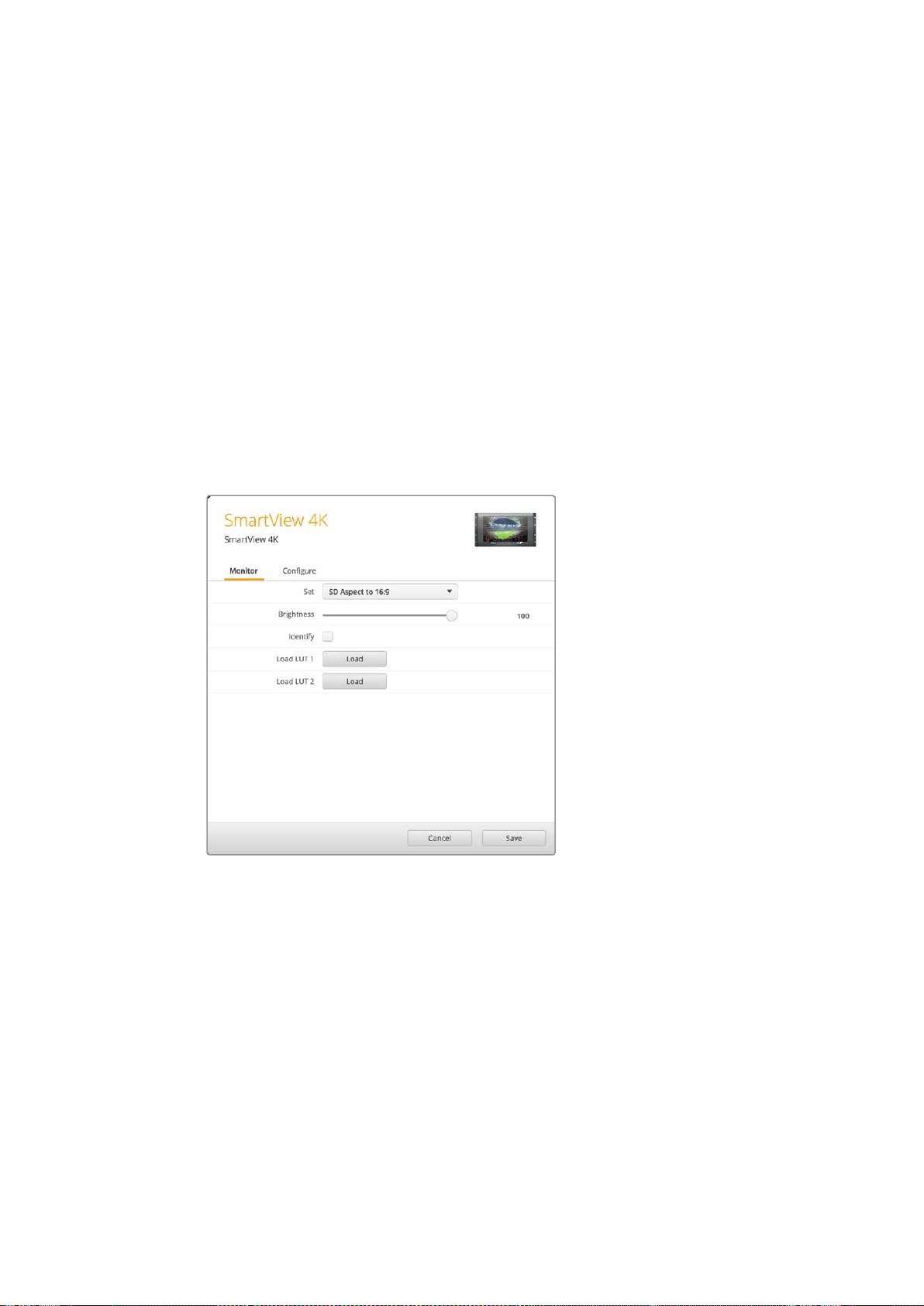
Blackmagic
SmartView
Setup
을 사용해
3D
LUT
로딩하기
SmartView
4K
에서는
3D
LUT
을 사용해 비디오를 모니터링할 수 있습니다
.
이를 통해 전문 보정
LUT
으로
SmartView
4K
를 보정하거나 최종 그레이징 작업을 마친 결과물과 가장 흡사한 영상을
확인할 수 있습니다
.
3D
LUT
을 사용해 각기 다른 영상룩을 적용해볼 수도 있습니다
.
Blackmagic
SmartView
Setup
소프트웨어를 사용해
LUT
을
SmartView
4K
에 로딩할 수 있습니다
.
SmartView
4K
는
.cube
파일 확장자 형식의 업계 표준
LUT
을 지원하기 때문에
Blackmagic
DaVinci
Resolve
에서
생성된 커스텀
LUT
을 로딩할 수도 있습니다
.
LUT
파일 생성에 관한 자세한 정보는
DaVinci
Resolve
설명서를 참고하세요
.
3D
LUT
1
에
3D
LUT
을 로딩하는 방법
Blackmagic
SmartView
Setup
소프트웨어를 실행하세요
.
Load
LUT
1
에 있는
Load
버튼을 누르세요
.
불러오려는
LUT
파일의 위치를 묻는 창이 나타납니다
.
원하는
.cube
LUT
파일을 선택한 뒤
,
Open
버튼을 누르세요
.
방금 로딩한
LUT
파일을 보려면
SmartView
4K
컨트롤 패널에 있는
3D
LUT
1
버튼을 누르세요
.
이 버튼을 다시 누르면
LUT
기능이 해제됩니다
.
같은 과정을 반복해
LUT
파일을
3D
LUT
2
에 로딩할 수 있습니다
.
Blackmagic
SmartView
Setup
을 사용하여
SmartView
4K
에
3D
LUT
을 로딩하세요
.
242SmartView
4K
사용하기
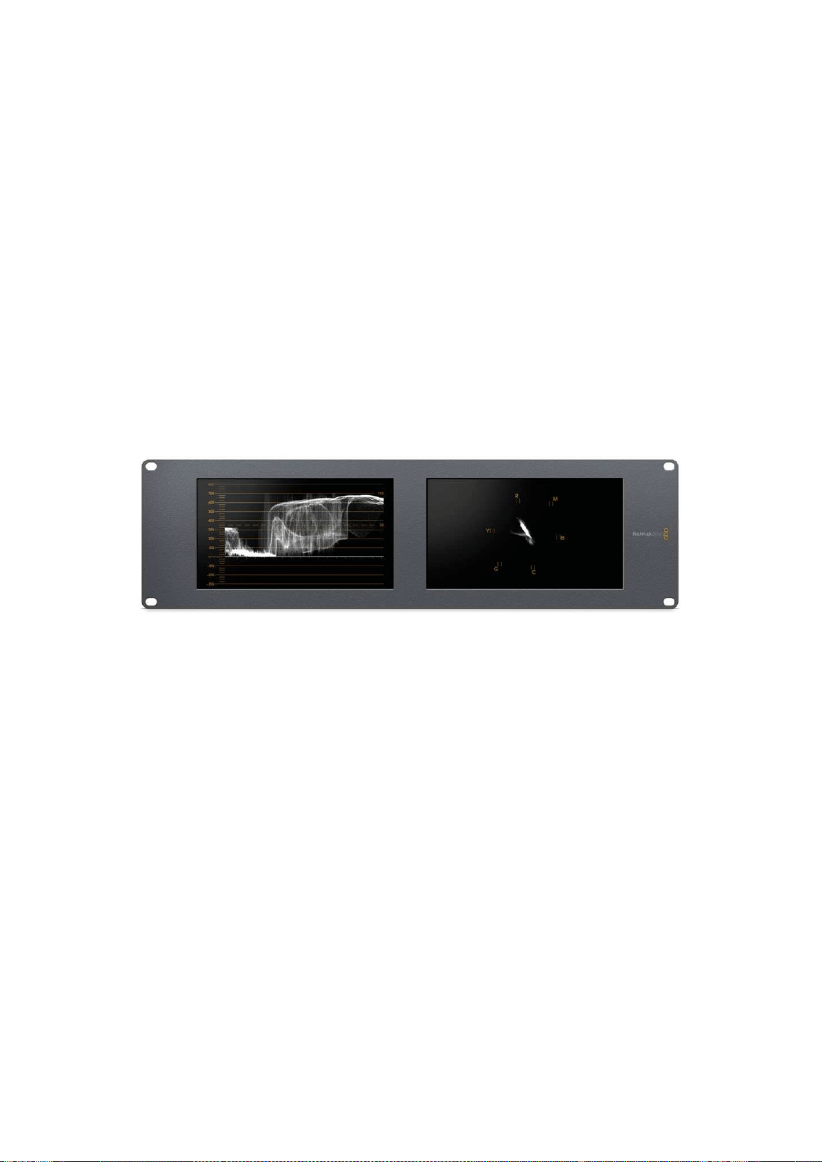
SmartScope
Duo
4K
사용하기
Blackmagic
SmartScope
이란
?
과거에는 방송 품질의
TV
스코프와 및 포스트 프로덕션 스코프는 상당히 값비싼 커스텀
솔루션이었으며 작은 스크린에서 한 번에 하나의 스코프만 볼 수 있었습니다
.
일부 스코프는 미관상
보기 좋지 않아 고객에게 안 좋은 인상을 주기도 합니다
.
SmartScope
Duo
4K
는 추가 파형 모니터를 지원해 듀얼 모니터에서 비디오 신호의 모든 부분을
실시간으로 확인할 수 있습니다
.
Blackmagic
SmartView
Setup
소프트웨어에서 입력 신호에 적용한
모든 조정 사항은
SmartScope
Duo
4K
에서 바로 확인할 수 있습니다
.
게다가
SDI
루프 출력을 통해
각 입력 신호를 양쪽의 모니터 중 하나로 전송할 수 있습니다
.
따라서 우측 모니터에는 좌측 모니터로
전송되는 신호를 위한 스코프가 나타납니다
.
SmartScope
Duo
4K
에 나타나는 스코프는
Blackmagic
SmartView
Setup
소프트웨어에서 선택할
수 있습니다
.
Display
드롭다운 메뉴에서 스코프를 선택하세요
.
아래 부분과 다음 몇 페이지에는 각 스코프 디스플레이를 사용하는 방법이 소개되어 있습니다
.
이를 통해 각 디스플레이 작동법을 심도 있게 이해할 수 있습니다
.
Blackmagic
SmartView
Setup
소프트웨어를 사용해
Blackmagic
SmartScope
Duo
4K
의 각 모니터에 서로 다른
스코프가 나타나도록 손쉽게 설정할 수 있습니다
.
비디오 모니터링
(Video
Monitoring)
디스플레이
비디오 모니터링
(Video
Monitoring)
디스플레이는
SmartScope
에서 수신되는 비디오를 확인할 수
있는 간편한 컨피던스 모니터입니다
.
SD
입력을 연결한 경우
Set
드롭박스 메뉴에서 종횡비를
4:3
필러박스 또는
16:9
로 선택할 수
있습니다
.
해당 뷰를 통해
LCD
밝기
,
콘트라스트
,
채도 설정에 적용된 모든 변경 사항을 바로 확인할
수 있습니다
.
이러한 설정 변경은 비디오 신호가 아닌 모니터 상에서만 적용된다는 사실을 기억하세요
.
따라서 채도 및 밝기 변화는 스코프에 어떠한 영향도 끼치지 않습니다
.
243SmartScope
Duo
4K
사용하기

한 모니터를 비디오 모니터링
(Video
Monitoring)
으로
,
다른 하나를 스코프 보기로 설정해 두면 아주
유용합니다
.
이를 위해 짧은 케이블을 사용하여
MONITOR
1
의
SDI
루프 출력과
MONITOR
2
의
SDI
입력을 연결하세요
.
SD
비디오를
4:3
필러 박스 또는
16:9
와이드스크린으로
보려면
Blackmagic
SmartView
Setup
소프트웨어의
Set
항목에서 원하는 종횡비를 선택하세요
.
애너모픽
SD
비디오를 모니터링할 경우
SD
Aspect
to
16:9
로 설정하세요
.
비디오 모니터링 디스플레이 설정을 통해
TV
화면이나 모니터에 나타나는 것과 동일한 비디오 신호를 볼 수 있습니다
.
파형
(Waveform)
디스플레이
파형 디스플레이는 일반 휘도 파형 모니터와 유사한 형태의 디지털 방식으로 인코딩된 파형을
제공합니다
.
휘도 파형 모니터는 비디오 신호의 루마 또는 밝기 수준을 모니터링 및
조정 하는 데 사용됩니다
.
기 존 휘 도 파형 모니터 는 컴 포 지 트 아날로 그
SD
비디오만 지원하는 반면
SmartScope
Duo
4K
의
파형 보기는
SD
뿐만 아니라
UHD
및
HD
또한 지원하므로
,
HD
디지털 비디오 포맷을 모니터링할
시에도 일관된 방식으로 루마 수준을 쉽게 조절할 수 있습니다
.
Blackmagic
SmartView
Setup
소프트웨어의
Display
드롭다운 메뉴에서
Waveform
을 선택하세요
.
방송 규정에 적합한 신호를 얻으려면 파형의 블랙이
0%
보다 낮고 화이트가
100%
를 넘지
않도록 해야 합니다
.
파형 모니터는 이미지를 그래픽으로 표현한 것으로
,
프레임 내의 동일 위치에 해당하는 루마 값을
시각적으로 볼 수 있습니다
.
예를 들어
,
영상 속 하늘의 일부가 빛에 과다 노출되면 파형 디스플레이에서
프레임의 가로 위치에 나타나는 수치를 시각적으로 확인할 수 있습니다
.
파형은 영상에 따라 여러 가지 형태로 나타납니다
.
콘트라스트가 높은 영상을 모니터링할 경우
미드 그레이 색상의 값이 나타나지 않을 수 있습니다
.
다음 화면을 통해 빛에 고르게 노출되어
좌측의 어두운 부분과 프레임 우측의 밝은 부분이 나타난 이미지 파형을 확인할 수 있습니다
.
244SmartScope
Duo
4K
사용하기

휘도 값을 보여주는 파형 디스플레이
.
Blackmagic
SmartView
Setup
소프트웨어의
Display
항목에서
Waveform
을
선택하면 비디오 신호의 루미넌스 값을 볼 수 있습니다
.
벡터 스코프
(Vectorscope)
디스플레이
벡터 스코프
(Vectorscope)
디스플레이는 벡터 보기를 사용하여 비디오 신호의 색을 나타냅니다
.
시설에서 사용하는 컬러바 테스트 신호의 표준에 따라
Blackmagic
SmartView
Setup
소프트웨어의
Set
드롭다운 메뉴를
100%
또는
75%
로 선택하세요
.
일부 사용자들은 벡터 스코프를 사용하여 방송 규정에 부적합한 수준의 색상을 확인할 수 있다고
생각하지만 이는 사실이 아닙니다
.
실제로는 퍼레이드
RGB
디스플레이를 사용해 규정 색상을
확인해야 합니다
.
벡터 스코프로 방송 규정에 부적합한 수준을 확인할 수 없는 이유는 크로마와
휘도값이 둘 다 필요하기 때문입니다
.
예를 들어
,
비디오의 색상이 화이트 및 블랙 포인트에 가깝게
나타나면 채도를 높여서 미드 그레이로 사용하는 것은 불가능합니다
.
벡터 스코프 디스플레이는
휘도값을 배제한 색상만을 보여주기 때문에 이것만으로는 방송 규정 색상을 확인할 수가 없습니다
.
벡터 스코프 디스플레이는 크로마 수준 조절이 필요한 구형 아날로그 비디오 테이프의 색상 수준을
확인할 때 사용하기 가장 적합한 도구입니다
.
비디오 테이프의 컬러바 부분을 재생한 뒤 크로마와
휴 설정을 조절하여 눈금판에 있는 사각형 색상 상자의 비디오 색상을 설정합니다
.
245SmartScope
Duo
4K
사용하기

벡터 스코프 디스플레이는 영상의 화이트 밸런스가 정확한지 또는 색상 집중 현상이 있는지를
확인할 수 있어 컬러 그레이딩에도 적합합니다
.
색상 집중 현상이 영상에서 발견되면 벡터 스코프
디스플레이는 중심에서 멀어지고 두 개의 중심점이 나타납니다
.
일반적으로 비디오 신호의 블랭킹
구간은 벡터 스코프의 중심에 점으로 나타납니다
.
그 이유는 비디오의 블랭킹 구간은 색상이 없는
검정 신호이기 때문입니다
.
블랭킹 구간은 색상 정보가 없는 검정 신호 부분을 확인할 수
있는 기준점입니다
.
비디오에 색상 집중 현상이 나타나는 경우 중심과 컬러박스에서 스코프가 멀어지는 것을 볼 수
있습니다
.
중심에서 멀어진 정도가 비디오의 색상 집중 현상의 정도를 나타내어 비디오의 블랙
/
화이트 색상의 변화를 모두 확인할 수 있습니다
.
이러한 벡터 스코프의 기능을 사용하여 색상 집중
현상을 없애고 정확한 화이트 밸런스를 유지할 수 있습니다
.
벡터 스코프 디스플레이를 통해 의도하지 않은 블랙
/
화이트의 색상 집중 현상 없이 영상의 색상을
한계 지점까지 끌어올릴 수 있습니다
.
색 균형은
RGB
퍼레이드 디스플레이와 벡터 스코프 디스플레이로
모니터링이 가능하지만 벡터 스코프 디스플레이에서 색균형의 문제점을 더욱 쉽게 확인할 수 있습니다
.
특히
,
얼굴 피부톤을 색보정하는 경우 따뜻한 색을 위한 채도를 유지하려면
,
벡터 스코프를
10
시
방향으로 조절합니다
.
이러한 색은
'
피부톤 라인
'
이라고 불리며 피부 표면에 혈색을 띠는 자연스러운
스킨 색상을 말합니다
.
그러므로 피부톤 라인은 모든 피부색에 적용할 수 있으며 연기자의 피부톤을
자연스럽게 표현할 수 있는 가장 좋은 방법입니다
.
10
시 방향으로 피부톤 라인을 보여주는 벡터 스코프 디스플레이
.
벡터 스코프를
100%
또는
75%
컬러바 테스트로 설정하세요
.
246SmartScope
Duo
4K
사용하기
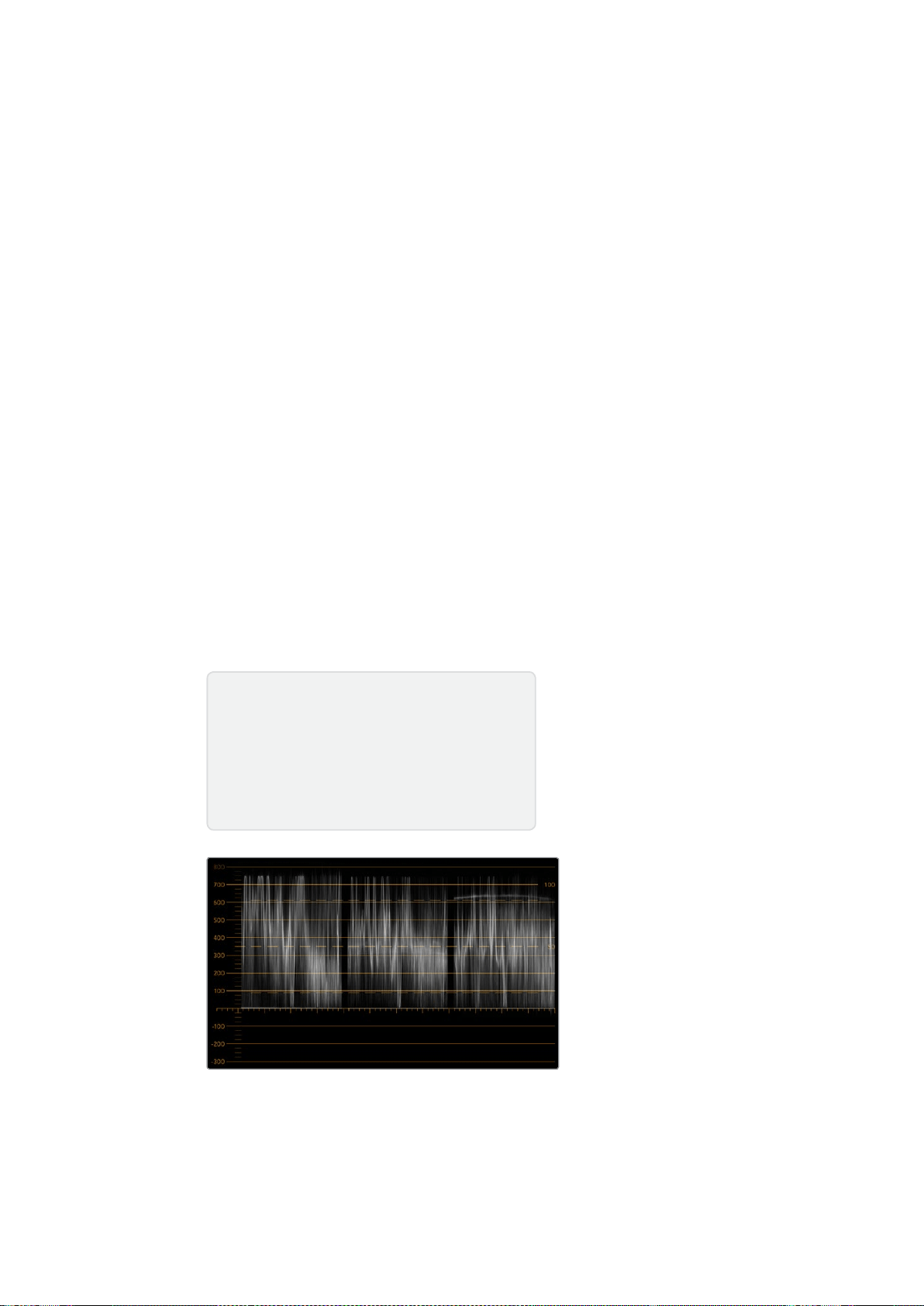
퍼레이드
(Parade)
디스플레이
RGB
및
YUV
퍼레이드 디스플레이는 색보정 작업과 부적절한 컬러 및 레벨 확인에 사용하기 완 벽합니다
.
색보정 작업 시
Blackmagic
SmartView
Setup
소프트웨어의
Display
드롭다운 메뉴에서
RGB
Parade
를 선택하세요
.
RGB
퍼레이드 뷰를 통해 전체 길이가 표시된 빨강
,
초록
,
파랑 색상의 채널이
개별적으로 표시됩니다
.
각 컬러 채널의 레벨을 모니터링하여 색보정 작업을 간단히 진행할 수
있으며
,
비디오의 블랙
,
중간톤
,
화이트 신호 색균형 또한 손쉽게 확인할 수 있습니다
.
RGB
퍼레이드
디스플레이를 통해 각 빨강
,
초록
,
파랑 채널의 디테일을 확인할 수 있어 색상 균형을 간단히 맞추고
원치 않는 색상 집중 현상을 제거할 수 있습니다
.
색보정 시 비디오 레벨이 최대로 올라가되 클리핑되지 않도록 하는 것이 중요합니다
.
비디오 신호
레벨을 올리고 싶은 경우
RGB
한도 범위를 넘거나 방송 규정 수준을 넘지 않도록 주의하세요
.
규정
수준인
100%
RGB
레벨을 넘지 않는 기기가 있지만 그렇지 않은 기기도 있습니다
.
SmartScope
Duo
4K
를 통해 방송 규정 수준을 넘을 때마다 이를 즉시 확인할 수 있습니다
.
규정상 부적절한 비디오 레벨은 블랙 및 화이트 레벨에서도 나타날 수 있습니다
.
일부 색보정
시스템에서는 블랙 포인트
0%
이하의 블랙 레벨이 생성될 수도 있습니다
.
규정상 부적절한 블랙
레벨을 발견할 시
,
Lift
또는
Gain
의 값을 조절해 이를 제거할 수 있습니다
.
이때
100%
눈금 레벨을
확인하 여 전체 비디오 신호가 규정 수준을 넘거나 부적절한 화이트 신호가 발생하지 않도록 주의하세요
.
YUV
레벨을 확인하려면
Display
드롭다운 메뉴에서
YUV
Parade
를 선택하세요
.
이 뷰는
TV
방송용
비디오 신호 형식이며 루마
(
밝기
)
값이 크로마
(
컬러
)
값으로부터 분리되어 표시되기 때문에 유용합니다
.
좌측 파형에는 루마 정보가 표시되며 두 번째 및 세 번째 파형에는 크로마 정보가 표시됩니다
.
YUV
퍼레이드 뷰는 비디오 신호의 크로마 값을 컬러바 테스트 패턴으로 조정하는데 유용합니다
.
이를
통해 색상을 정확하게 나타낼 수 있으며
TV
세트에서 디스플레이할 수 있는 방송 신호를
얻을 수 있습니다
.
색보정 작 업은 방 송 규 정상 허용되는 범위에서 최고의 영 상 이미지를 얻기 위해 영상 을 지속적으로
조정하는 과정입니다
.
RGB
퍼레이드 뷰
색보정 용어
블랙
–
비디오 신호의 블랙 레벨
미드톤
–
비디오 신호의 미드 그레이 레벨
화이트
–
비디오 신호의 화이트 레벨
247SmartScope
Duo
4K
사용하기
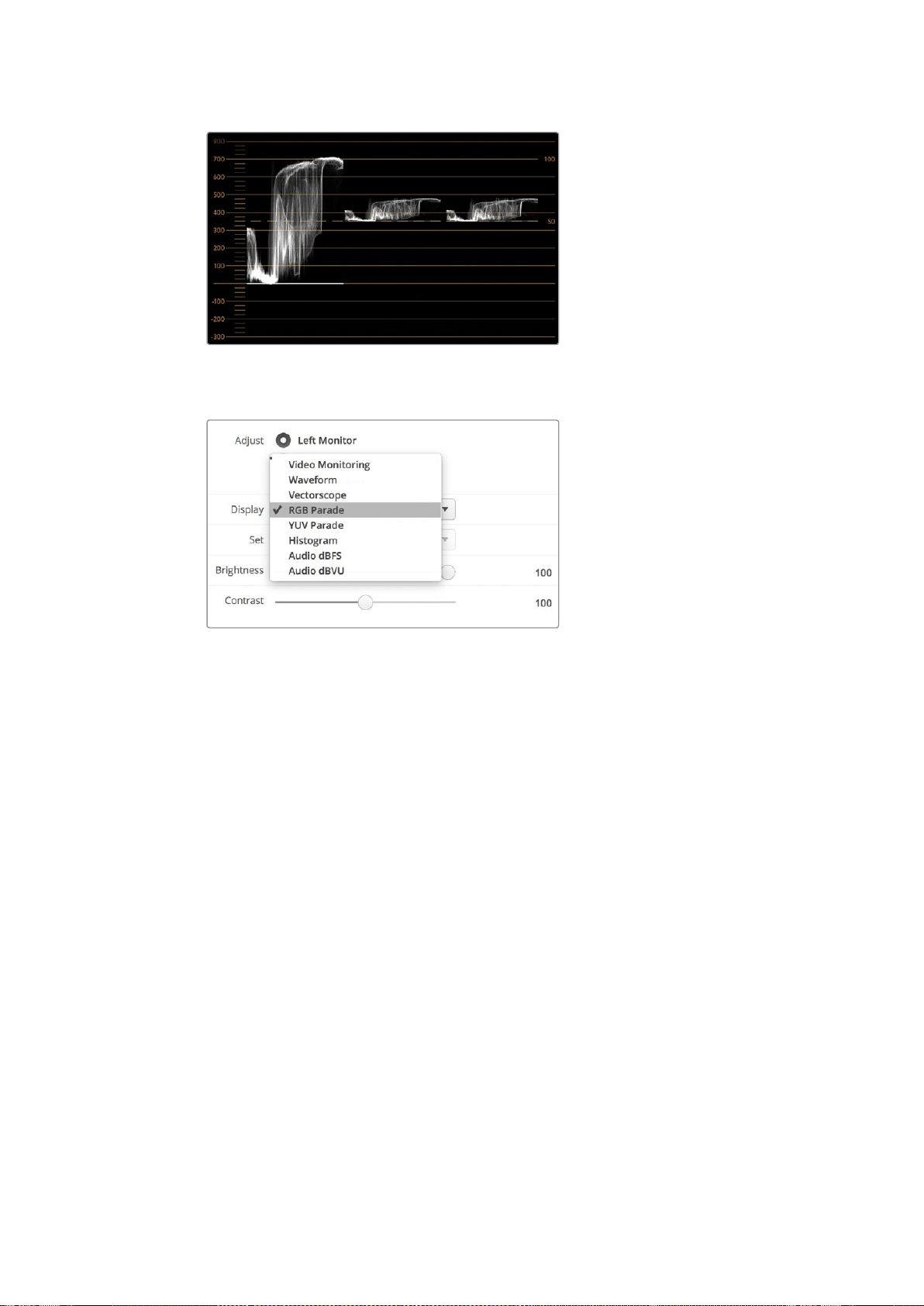
YUV
퍼레이드 뷰
Blackmagic
SmartView
Setup
소프트웨어의
Display
드롭다운
메뉴에서
RGB
Parade
및
YUV
Parade
를 선택하세요
.
히스토그램
(Histogram)
디스플레이
히스토그램 디스플레이는 그래픽 디자이너와 카메라 운영자에게 가장 익숙한 디스플레이입니다
.
히스토그램 디스플레이는 화이트에서 블랙까지의 색상 분포 정보를 보여주며 비디오의 화이트 및 블
랙 정보의 클리핑 여부를 모니터링할 수 있습니다
.
히스토그램 디스플레이는 비디오에 적용된 감마
효과를 보여줍니다
.
블랙 비디오는 디스플레이 왼쪽에 그리고 화이트 비디오는 오른쪽에 나타납니다
.
일반적으로 모든
비디오는 히스토그램 디스플레이의
0%
와
100%
사이에 나타납니다
.
비디오가
0%
미만이거나
100%
를
초과하면 클리핑된 것을 의미합니다
.
촬영 중에 비디오 클리핑 현상이 발생하면 곤란할 수 있습니다
.
왜냐하면
,
블랙
/
화이트의 디테일을 보존해야 나중에 통제된 환경에서 색보정 작업을 수행할 수
있기 때문입니다
.
촬영 시 비디오를
0%
이상의 블랙 클리핑 범위와 화이트 클리핑 범위 안으로
제한하면 나중에 더욱 자유롭게 색조정 작업을 할 수 있습니다
.
색보정 중에 비디오를 클리핑해야 하는 경우가 생길 수도 있습니다
.
이러한 경우에 히스토그램
디스플레이에서 비디오의 클리핑 효과를 보고 얼마나 클리핑 되었는지를 확인할 수 있습니다
.
약간의 클리핑 효과로 더 많은 디테일을 유지한 채 감마를 사용하면 비슷한 장면을 연출할 수 있습니다
.
히스토그램 디스플레이를 통해 부적절한 블랙
/
화이트는 확인이 가능하지만
,
방송 규정에 부적합한
수준을 확인할 수는 없습니다
.
히스토그램 디스플레이는 색상을 나타내지 않기 때문에 비디오에
포함된 부적절한 색상도 규정 범위 내의 수준으로 나타날 수가 있습니다
.
RGB
퍼레이드 디스플레이는
비디오 신호의 색상과 휘도를 모두 보여주기 때문에 방송 규정 수준을 확인하기에 가장 적합합니다
.
248SmartScope
Duo
4K
사용하기

화이트 및 블랙의 분포 정도를 보여주는
히스토그램 디스플레이 설정
Blackmagic
SmartView
Setup
소프트웨어의
Display
드롭다운 메뉴에서
Histogram
을 선택하세요
.
오디오 미터링 표시
오디오 미터링 표시는
SDI
비디오 신호에 임베드된 오디오 수준을 나타냅니다
.
최대
16
채널의
임베디드 오디오가 디임베드되어
dBVU
또는
dBFS
형식으로 표시됩니다
.
신호의 평균 레벨을 나타내는
VU
미터는 사용이 편리하며 오래된 장비에서 주로 사용됩니다
.
VU
는
SMPTE
권장 신호인
-20
dBFS
로 설정된
1
kHz
톤의 테스트 신호를 사용합니다
.
dBFS
는 본래 전체 디지털 오디오 신호를 측 정하기 위한 단위로 서 현대 디지털 기기에서 흔히 사 용됩니다
.
우측 오디오 스코프에서
2
개의 오디오 채널을 모니터링할 수 있습니다
.
해당 채널은
Set
드롭다운
메뉴에서 선택할 수 있습니다
.
예
)
채널
1
&
2
또는 채널
3
&
4
등
.
오디오 스코프는
X/Y
축에 오디오를
나타내므로 오디오 밸런스 문제 및 위상 상태를 확인할 수 있고 오디오 트랙이 모노인지 또는
스테레오인지를 확인할 수 있습니다
.
모노 오디오인 경우 하나의 수직선
In
Phase
라인으로
나타납니다
.
이 라인이 수평으로 나타나면 오디오가 ‘위상 반전’ 상태임을 나타내며
,
다운스트림
장비에서 신호를 전송받을 시 오디오 손실과 같은 현상이 나타날 수 있습니다
.
오디오 위상은 대형
시설에서 케이블이 제대로 연결되어 있지 않은 경우 가장 흔히 일어나는 오디오 결함 중 하나입니다
.
249SmartScope
Duo
4K
사용하기
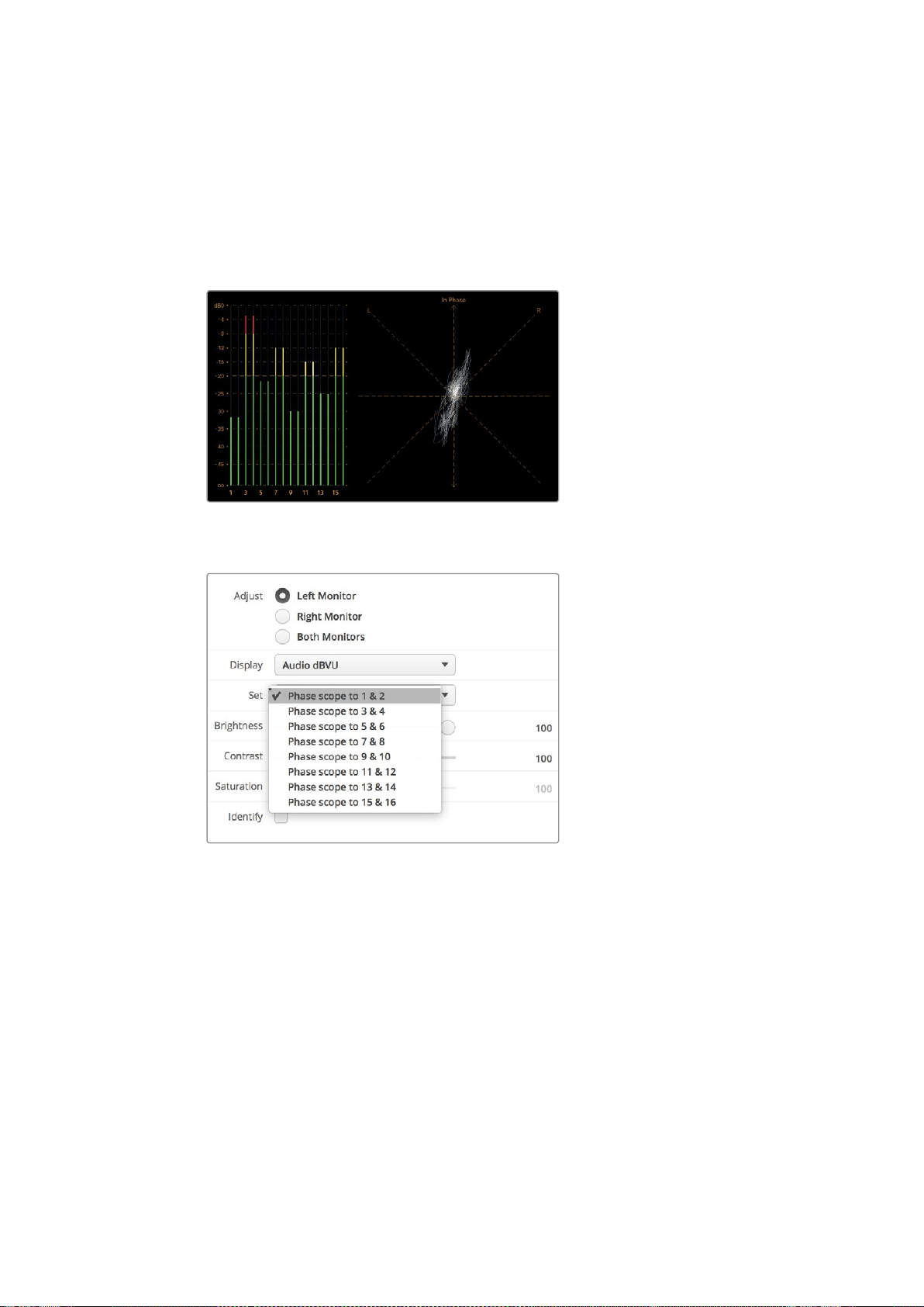
스테레오 신호를 모니터링할 시에는 우측 오디오 스코프에서 신호 표시가 좌
/
우 오디오 채널의
차이에 따라 퍼져서 나타납니다
.
오디오 트랙의 스테레오 사운드가 더욱 많을수록 신호 표시가
더욱 둥글게 나타납니다
.
오디오에 스테레오 콘텐츠가 적게 포함되어 있을수록 신호 표시는 수직선
주위에 더욱 집중됩니다
.
다이얼로그 오디오는 수직 라인으로 나타나는 경향이 있는 반면
,
스테레오 콘텐츠가 많이 포함된
음악은 스코프가 볼록하게 부풀어 나타납니다
.
그 이유는 모노 오디오가
L+ R
이고 수직축에 나타나는
반면
,
스테레오 콘텐츠는
L-R
이며 가로축에 나타나 스테레오 간의 차이를 보여주기 때문입니다
.
피크 레벨 및 오디오 밸런스를 보여주는 오디오 미터링 디스플레이
.
Set
드롭다운 메뉴에서 모니터링할 오디오 채널 조합을 선택하세요
.
네트워크에 연결하기
SmartView
또는
SmartScope
모니터를 네트워크에 연결해 여러 유닛의 모니터 설정을 원격으로
조정할 수 있습니다
.
SmartView
및
SmartScope
모니터에서는 어떠한 환경 설정 없이도 비디오를 디스플레이할 수
있지만
,
유닛을 배치하기 전에 네트워크 환경을 설정해야 합니다
.
네트워크 환경 설정 작업은
컴퓨터에 직접 연결된
USB
를 통해서만 가능합니다
.
다이렉트 이더넷
컴퓨터에 연결된 다이렉트 이더넷 연결을 통해 모니터 환경을 원격으로 설정할 수 있습니다
.
해당
환경 설정엔 네트워크 스위치가 따로 필요 없기 때문에 신속한 설치 및 설정이 필요한 상황에
250
네트워크에 연결하기
유용합니다
.
각 유닛의 액티브 루프스루 이더넷 출력 포트를 사용해 추가 유닛을 데이지 체인
방식으로 연결할 수 있습니다
.
데이지 체인 방식으로 연결된 모든 유닛의 전원을 반드시 연결하세요
.
기존 스튜디오 네트워크의
IP
주소를 사용하지 않고 여러 대의 유닛을 연결하고자 하거나 기존
네트워크가 없는 경우에는 간단히 컴퓨터 이더넷 포트에 직접 연결하세요
.
네트워크 스위치 연결용
케이블을 따로 사용할 필요가 없기 때문에 이더넷을 통해
SmartView
및
SmartScope
유닛을
신속하게 연결할 수 있습니다
.
이더넷 커넥터
이더넷 네트워크 스위치
스튜디오 네트워크에 여러 대의 유닛을 연결하고자 할 경우 한 대의
SmartView
또는
SmartScope
를
네트워크 스위치에 연결한 다음 각 유닛의 액티브 루프스루 이더넷 출력 포트를 통해 나머지 유닛을
데이지 체인 방식으로 간단히 연결할 수 있기 때문에 스위치에 있는 포트는 하나만 사용하면 됩니다
.
덕분에 네트워크 스위치 뒷면에 여러 개의 케이블을 연결할 필요가 없습니다
.
단
,
데이지 체인
방식으로 연결된 모든 유닛의 전원을 연결해야 작동합니다
.
네트워크 스위치에 연결하면 네트워크 상의 모든 컴퓨터를 통해 유닛 설정을 변경할 수 있습니다
.
네트워크에 무선 중계 장치
(AP)
가 설치되어 있는 경우 모든
Mac
또는
Windows
노트북 컴퓨터에서도
WiFi
연결을 통해 설정을 변경할 수 있습니다
.
SmartView
또는
SmartScope
를 인근
IP
기반 네트워크에 연결하려면 다음 단계를 따르세요
.
제품에 포함된 전원 공급 장치를 안전하게 연결한 다음 전원을 켜세요
.
표준
RJ45
이더넷 케이블로 유닛과 스위치를 연결하거나 컴퓨터에 직접 연결합니다
.
251
네트워크에 연결하기
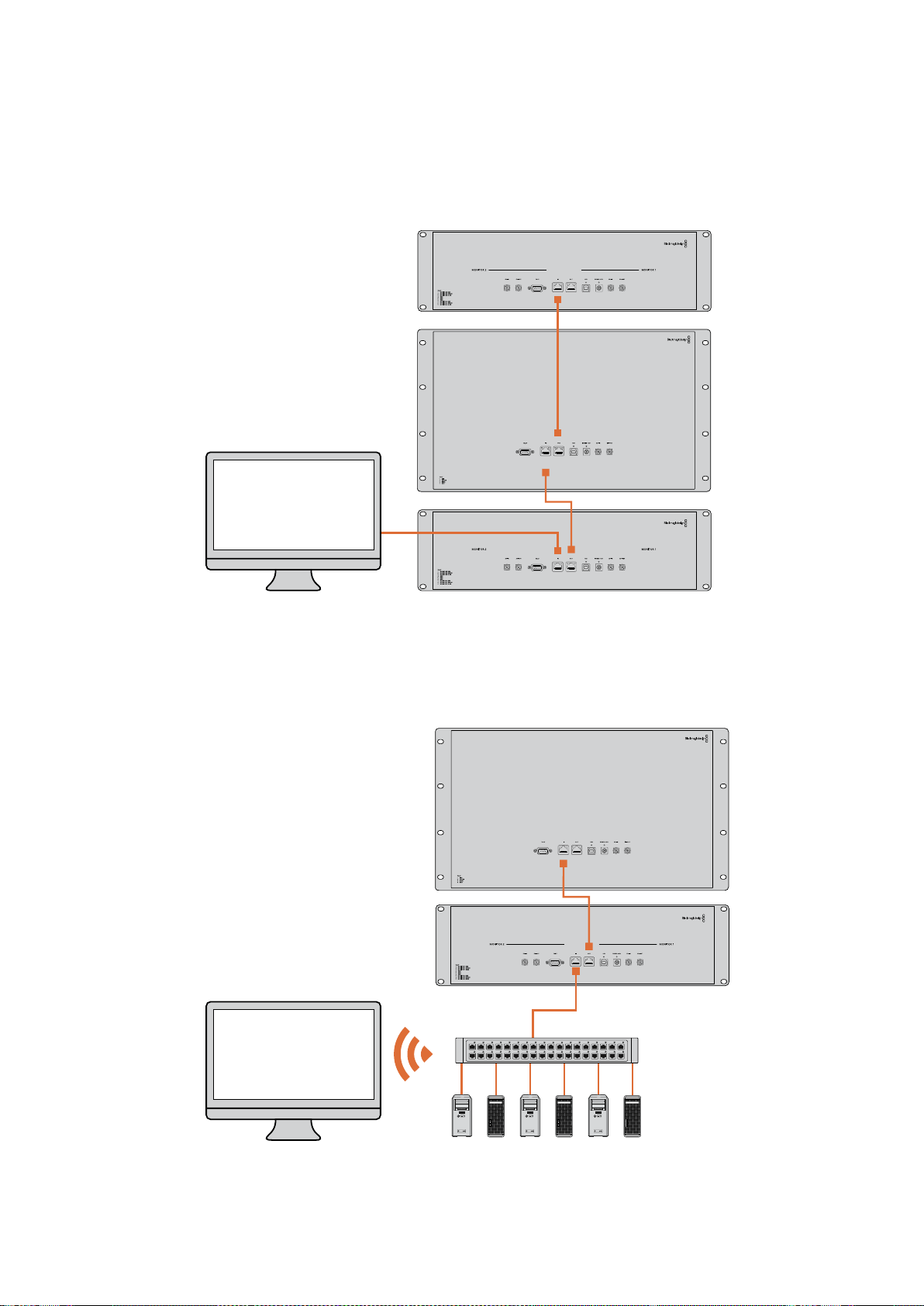
다이렉트 이더넷 연결 도면
네트워크 스위치를 사용하지 않고도 컴퓨터의 이더넷 포트를 유닛에 직접 연결할 수 있습니다
.
추가
유닛을 데이지 체인 방식으로 서로 연결할 수 있어 네트워크 스위치 뒤에 여러 개의 케이블을 연결할
필요가 없습니다
.
단
,
모든 유닛의 전원을 반드시 연결하세요
.
이더넷 네트워크 스위치 연결 도면
스튜디오의 기존 네트워크에 여러 대의 유닛을 연결하고자 할 경우엔 유닛 한 대만 네트워크
스위치에 연결하면 됩니다
.
나머지 유닛을 데이지 체인 방식으로 서로 연결할 수 있어 네트워크
스위치 뒤에 여러 개의 케이블을 연결할 필요가 없습니다
.
단
,
모든 유닛의 전원을 반드시 연결하세요
.
SmartScope 4KDuo
SmartScope 4KDuo
네트워크 스위치
이더넷
클라이언트
컴퓨터
252
네트워크에 연결하기

네트워크 설정 조정하기
네트워크 설정
장치명
네트워크 상에서 각
SmartView
또는
SmartScope
유닛을 쉽게 확인할 수 있도록 모니터 이름을
변경하는 것이 좋습니다
.
예
)
Field
Cameras
1
&
2,
Multi-View
Output,
4K
feeds
등
.
모니터 이름을 변경하려면 먼저 모니터가 이더넷 또는
USB
를 통해 연결되어 있는지 확인하세요
.
Blackmagic
SmartView
Setup
소프트웨어를 실행한 뒤
,
모니터 이름 아래쪽에 있는 설정 아이콘을
클릭하세요
.
설정 페이지에서
Network
를 클릭한 다음
Details
섹션에서 모니터 이름을 변경하세요
.
소프트웨어에서 올바르지 않은 이름 입력이 감지될 경우 모니터 이름 옆에 경고 아이콘이 나타납니다
.
적합한 이름일 경우 녹색 체크 표시가 나타납니다
.
컴퓨터 키보드의
return
키를 누르면 이름
변경이 완료됩니다
.
네트워크 설정
Blackmagic
SmartView
Setup
소프트웨어의
Network
Settings
섹션을 변경하려면
,
Blackmagic
모니터와 컴퓨터를
USB
로 연결해야 합니다
.
이더넷 연결로는 네트워크 설정을 변경할 수 없습니다
.
SmartView
와
SmartScope
에서는
DHCP
를 사용해 네트워크에서
IP
주소를 자동으로 얻을 수 있도록
기본 설정되어 있습니다
.
DHCP
서버가 없는 상황에서는
macOS
의 인터넷 공유 기능이나
Windows
8.1
및
Windows
10
의
인터넷 연결 공유
(ICS)
기능을 활성화해
DHCP
주소를 직접 연결된 모든 유닛에 제공할 수 있습니다
.
그러면 고정
IP
주소를 각 유닛마다 수동으로 지정할 필요가 없습니다
.
이 기능을 사용하면 컴퓨터가
인터넷에 연결되어 있지 않은 상황에서도
DHCP
주소를 제공할 수 있습니다
.
인터넷 공유에 대한
자세한 정보는
macOS
와
Windows
8.1/10
의 도움말 문서를 참고하세요
.
환경 설정에서
DHCP
를 사용할 수 없는 경우
,
고정
IP
를 사용해 주소를 설정할 수 있습니다
.
네트워크에서
IP
충돌이 일어나지 않도록 시스템 관리자에게 다른
IP
주소를 요청세요
.
일반 서브넷
마스크뿐만 아니라 각
SmartView
및
SmartScope
유닛의 고유
IP
주소를 반드시 명시해야 합니다
.
유닛을 인터넷 라우터와 같은 네트워크 게이트웨이에 연결하고자 하는 경우가 아니라면
Gateway
필드에 있는 기본 설정값을 따로 변경할 필요가 없습니다
.
네트워크에
SmartView
및
SmartScope
모니터가 나타나지 않는다면 이는
DHCP
를 통해 유닛으로
IP
주소가 전달되지 않았기 때문일 수 있습니다
.
이런 경우엔 각 유닛의 네트워크 설정을 수동으로
적절히 조정해야 합니다
.
1
USB
를 사용해
Blackmagic
SmartView
또는
SmartScope
모니터와 컴퓨터를 연결한 다음
Blackmagic
MultiView
Setup
소프트웨어를 실행하세요
.
2
SmartView
Setup
소프트웨어 시작 화면에 연결된 모니터가 자동으로 나타나며
,
장비 이름
옆에
USB
아이콘이 나타납니다
.
3 모니터의 네트워크 설정을 조정하세요
.
4
DHCP
를 통해
IP
주소를 받지 못한 다른 유닛에서도 이 단계를 반복하세요
.
253
네트워크 설정 조정하기
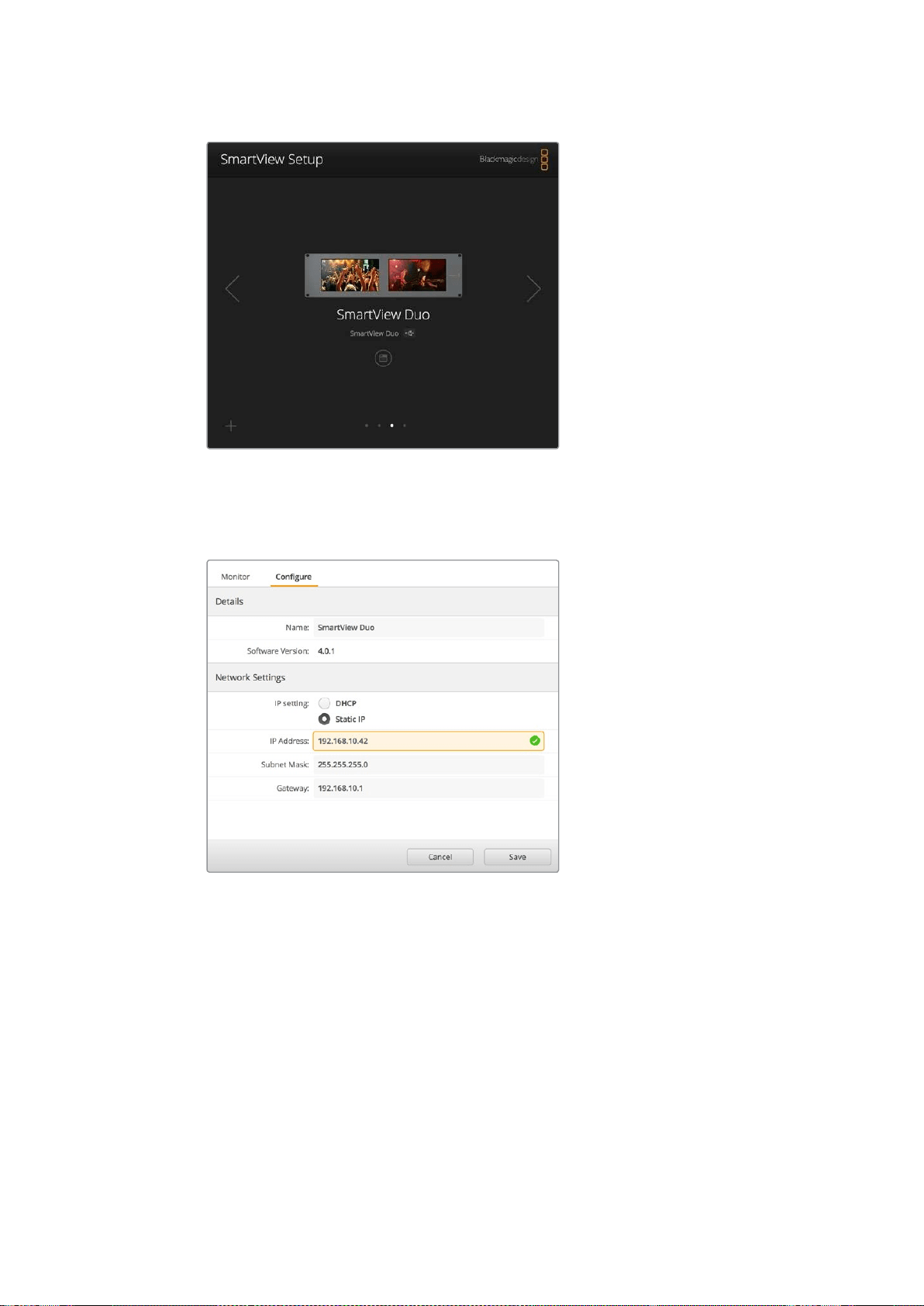
모니터 이름 옆에 나타난
USB
아이콘을 통해 모니터와 컴퓨터가
USB
로 연결되었음을 확인할 수 있습니다
.
네트워크 설정을
조정하려면
Blackmagic
모니터를
USB
로 연결하세요
.
네트워크 설정은
DHCP
또는
Static
IP
로 설정할 수
있으며 오직
USB
를 통해서만 변경할 수 있습니다
.
Blackmagic
모니터 추가하기
SmartView
또는
SmartScope
Duo
4K
의
IP
주소를 이미 알고 있지만
SmartView
Setup
소프트웨어
시작 화면에 자동으로 나타나지 않을 경우 모니터를 수동으로 추가할 수 있습니다
.
다음 순서에
따라 업데이트를 진행하세요
.
1
Blackmagic
모니터가 이더넷을 통해 연결되어 있는지 확인하세요
.
좌측 하단에 있는
+
아이콘을 클릭하면
Add
a
Blackmagic
Monitor
라는 창이 나타납니다
.
2 모니터의
IP
주소를 입력한 뒤
,
Add
버튼을 클릭하세요
.
3
소프트웨어에서 유닛을 인식하고 나면
SmartView
Setup
시작 화면의
Blackmagic
모니터에 해당 유닛이 추가됩니다
.
오른쪽 화살표 아이콘을 클릭하여 새롭게 추가된
모니터를 볼 수 있습니다
.
254
네트워크 설정 조정하기
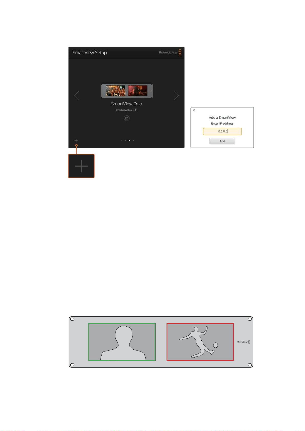
+
아이콘을 클릭한 뒤 모니터의
IP
주소를 입력해
SmartView
또는
SmartScope
모니터를 연결된 모니터 목록에 수동으로 추가할 수 있습니다
.
탈리 사용
탈리 포트 핀 연결
SmartView
또는
SmartScope
의 탈리 포트를 반드시 연결할 필요는 없습니다
.
탈리 기능을 사용하지
않을 경우엔 이 단계를 건너뛸 수 있습니다
.
각
SmartView
또는
SmartScope
화면에는 빨간색
/
녹색
/
파란색의 개별 탈리 보더가 나타나 현재
비디오 신호가 방송 중
,
미리보기
,
녹화 중임을 알 수 있습니다
.
9
핀
D-Sub
탈리 포트를 통해 스위처 및 자동화 시스템의 접점 폐쇄 신호를 연결할 수 있습니다
.
탈리 포트를 스위처 및 자동화 시스템과 함께 사용하기 위한 배선 관련 정보는 첨부된 탈리 핀 연결
배선 도면을 참고하세요
.
9
핀
D-Sub
포트 배선 관련 상세 정보는 제품 뒷면에 프린트되어 있습니다
.
이를 통해 개별 모니터에
빨간색
/
녹색
/
파란색 탈리 보더가 나타나게 하는 접점 폐쇄 관련 정보를 확인할 수 있습니다
.
SmartView
Duo
에 나타난 녹색 및 빨간색 탈리 보더
255
탈리 사용

시야각 최적화하기
SmartView
Duo,
SmartView
HD
또는
SmartScope
모니터를 장비랙의 높은 곳에 설치해야 할 경우
최적의 시야각을 위해
LCD
화면을 거꾸로 설치할 수도 있습니다
.
거꾸로 설치된 것이 감지될 경우
LCD
이미지가 자동으로 회전됩니다
.
전면판을 뒤쪽 어셈블리로부터 분리하거나 재조립할 경우
02
크기의
Pozidriv
드라이버가 필요합니다
.
이는 뒷면 어셈블리를 분해할 필요가 없는 아주
간단한 과정입니다
.
다음은 전면판에 있는
Blackmagic
Design
로고를 올바른 방향으로 유지한 채 유닛을 거꾸로
설치하는 방법에 대한 설명입니다
.
02
크기의
Pozidriv
드라이버가 필요합니다
.
1
전면판 상
/
하
/
좌
/
우에 있는 나사를 분리하세요
.
SmartView
Duo
와
SmartScope
Duo
4K
에는
10
개의 나사가
,
SmartView
HD
에는
18
개의 나사가 있습니다
.
2 아래 그림에 나온 것처럼 전면판을 뒷면 어셈블리로부터 떼어냅니다
.
3 위아래가 바뀌도록 뒷면 어셈블리를 회전시키세요
.
4 거꾸로 뒤집은 뒷면 어셈블리에 전면판을 재조립합니다
.
5 섀시에 나사를 다시 고정하세요
.
이제
SmartView
또는
SmartScope
를 장비랙 높은 곳에 설치할 준비가 완료되었습니다
.
장비랙에
고정하고 나면
SmartView
에 충격이 가해지더라도 잘못 눌러지거나 느슨해질 만한 외부 노브 또는
조절 장치가 없기 때문에 언제나 최적의 시야각을 제공합니다
.
SmartView
Duo
및
SmartScope
Duo
4K
탈리 핀 연결
핀 기능
1
모니터
1
빨간색
2
모니터
1
녹색
3
모니터
1
파란색
4
접지
5
접지
6
접지
7
모니터
2
빨간색
8
모니터
2
녹색
9
모니터
2
파란색
SmartView
HD
및
SmartView
4K
탈리 핀 연결
핀 기능
1
빨간색
2
초록색
3
파란색
4
접지
5 4 3 2 1
9 8 7 6
SmartView
탈리 포트
256
시야각 최적화하기
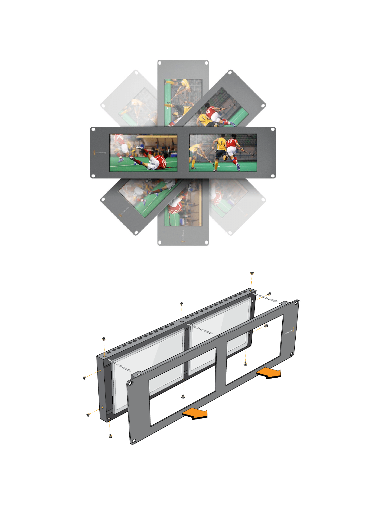

Developer Information
Developing Custom Software Using Blackmagic Design Hardware
The Blackmagic SmartView Ethernet Protocol allows developers to remotely control
Blackmagic SmartView and SmartScope hardware with their own custom software.
TheBlackmagic SmartView Ethernet Protocol is a text-based status and control protocol.
Downloading the Free SmartView EthernetProtocol
The Blackmagic SmartView Ethernet Protocol is free. It is included in this SmartView &
SmartScope manual and can be downloaded from www.blackmagicdesign.com/kr/support
Joining the Blackmagic Design Developer List
The Blackmagic Developer mailing list is designed for technical questions regarding
technologies used by Blackmagic Design, e.g., QuickTime, Core Media, DirectShow, codecs,
APIs, SDKs, etc. The free mailing list is a forum where developers can discuss ideas and
problems with other developers. Any subscriber may reply and the Blackmagic Design
engineers may also respond when appropriate. You can subscribe to the mailing list at:
http://lists.blackmagicdesign.com/mailman/listinfo/bmd-developer
In some cases, we might request a brief outline of the software you are developing if it is not
immediately obvious from your domain name that your organization develops video software.
Please don’t take offence as we’re simply trying to keep the list free of spam and viruses as well
as end-user customers asking non-development questions, employment agents or sales
people trying to promote products on the list. The list is just for developers.
Contacting Blackmagic Design DeveloperAssistance
You can also contact us via developer@blackmagicdesign.com if you have any developer
related questions or wish to ask questions off the list.
Blackmagic
2K
Format
–
Overview
Blackmagic Design products support 3G-SDI video, which allows twice the data rate of
traditional HD-SDI video. We thought it would be a really nice idea to add 2K film support,
via 3G-SDI technology, so we could simplify feature film workflows. With the popularity of
Blackmagic Design editing systems worldwide, now thousands of people can benefit from
a feature film workflow revolution.
258
시야각 최적화하기

This information includes everything product developers need to know for building native
2KSDI equipment. Of course, all Blackmagic products can be updated, so if the television
industry adopts an alternative SDI-based film standard, we can add support for that too!
Frame Structure
Transmitted at 23.98, 24 or 25 frames per second as a Progressive Segmented Frame.
Active video is 2048 pixels wide by 1556 lines deep.
Total lines per frame : 1650
Active words per line are 1535. One word consists of a 10-bit sample for each of the
four data streams, i.e., a total of 40 bits. See the diagram named Blackmagic 2K Format
- Data Stream Format.
Total active lines : 1556
Total words per line : 1875 for 23.98/24Hz and 1800 for 25Hz.
Fields per frame : 2, 825 lines each
Active lines located on lines 16-793 (field 1) and 841-1618 (field 2).
Transport Structure
Based on SMPTE 372M Dual Link mapping and SMPTE 425M-B support for mapping
SMPTE 372M into a single 3 Gb/s link.
Timing reference signals, line number and line CRC insertion is the same as above.
During active video, 10-bit Red, Green and Blue data is sent in the following sequence:
Optional ancillary data is inserted into both virtual interfaces.
At present, only audio data is included: as per standard HD audio insertion (SMPTE
S299M) the audio data packets are carried on data stream two and audio control
packets are carried on data stream one.
Data stream 1: Green_1, Green_2, Green_3, Green_5...Green_2047
Data stream 2: Blue_1, Blue_2, Green_4, Blue_5...Green_2048.
Data stream 3: Red_1, Blue_3, Blue_4, Red_5...Blue_2048.
Data stream 4: Red_2, Red_3, Red_4, Red_6...Red_2048.
Blackmagic
2K
Format
–
Vertical
Timing
Reference
This diagram shows the vertical timing details with line numbers and Field, Vertical and
Horizontal bits for the Timing Reference Signal codes.
Field 1 Active
F 1 0 0 0 0 0 0 0 0 0 0 0
V 1 1 1 1 1 1 0 0 0 0 1 1
LINE # 1650 1 2 ... 14 15 16 ... 792 793 ... 825
Field 2 Active
F 0 1 1 1 1 1 1 1 1 1 1 1
V 1 1 1 1 1 1 0 0 0 0 1 1
LINE # 825 826 827 ... 839 840 841 ... 1617 1618 ... 1650
259
시야각 최적화하기
Blackmagic
2K
Format
–
Data
Stream
Format
This diagram shows the data stream formats around the optional ancillary data section of the
horizontal line. Note that each active pixel takes up three samples.
Data Stream 1
G2041
G2042
G2043
G2045
G2046
G2047
EAV(3FFh)
EAV(000h)
EAV(000h)
EAV(XYZh)
LN0
LN1
CRC0
CRC1
ANC/Audio
Data
SAV(3FFh)
SAV(000h)
SAV(000h)
SAV(XYZh)
G1
G2
G3
G5
Data Stream 2
B2041
B2042
G2044
B2045
B2046
G2048
EAV(3FFh)
EAV(000h)
EAV(000h)
EAV(XYZh)
LN0
LN1
CRC0
CRC1
ANC/Audio
Data
SAV(3FFh)
SAV(000h)
SAV(000h)
SAV(XYZh)
B1
B2
G4
B5
Data Stream 3
R2041
B2043
B2044
R2045
B2047
B2048
EAV(3FFh)
EAV(000h)
EAV(000h)
EAV(XYZh)
LN0
LN1
CRC0
CRC1
040
…
040
SAV(3FFh)
SAV(000h)
SAV(000h)
SAV(XYZh)
R1
B3
B4
R5
Data Stream 4
R2042
R2043
R2044
R2046
R2047
R2048
EAV(3FFh)
EAV(000h)
EAV(000h)
EAV(XYZh)
LN0
LN1
CRC0
CRC1
200
…
200
SAV(3FFh)
SAV(000h)
SAV(000h)
SAV(XYZh)
R2
R3
R4
R6
Word#
23.98/24 PsF
1870
1871
1872
1873
1874
1875
1
2
3
4
5
6
7
8
9
…
335
336
337
338
339
340
341
342
343
Word#
25 PsF
1795
1796
1797
1798
1799
1800
1
2
3
4
5
6
7
8
9
…
260
261
262
263
264
265
266
267
268
260
시야각 최적화하기

Blackmagic
SmartView
Ethernet
Protocol
v1.3
Summary
The Blackmagic SmartView Ethernet Protocol is a text-based status and control protocol, very
similar in structure to the Videohub protocol, that is accessed by connecting to TCP port 9992
on a SmartView or SmartScope device.
Upon connection, the SmartView or SmartScope device sends a complete dump of the state
of the device. After the initial dump, state changes are sent asynchronously.
The device sends information in blocks which have an identifying header, followed by a colon.
A block can span multiple lines and is terminated by a blank line.
To be resilient to future protocol changes, clients should ignore blocks they do not recognize,
up to the trailing blank line. Within recognized blocks, clients should ignore lines they do not
recognize.
Version 1.3 of the Blackmagic SmartView Ethernet
Protocol was released with SmartView 1.3 software.
Protocol Preamble
The first block sent by the SmartView Server is always the protocol preamble:
PROTOCOL PREAMBLE:
↵
Version: 1.3
↵
↵
The version field indicates the protocol version. When the protocol is changed in a compatible
way, the minor version number will be updated. If incompatible changes are made, the major
version number will be updated.
Device Information
The next block contains general information about the connected SmartView or SmartScope
device.
SMARTVIEW DEVICE:
↵
Model: SmartView Duo
↵
Hostname: stagefront.studio.example.com
↵
Name: StageFront
↵
Mo nitor s: 2
↵
Inverted: false
↵
↵
This example shows the output for a SmartView Duo device, which has two LCDs.
The INVERTED flag indicates whether the device has detected that it has been mounted in an
inverted configuration to optimize LCD viewing angle.
Legend
↵
carriage return
… and so on
261
시야각 최적화하기

Network Configuration
The next block shows the TCP/IP networking configuration:
NETWORK:
↵
Dynamic IP: true
↵
Static address: 192.168.2.2
↵
St atic netm as k: 255.255.255.0
↵
St atic gatew ay: 192.168.2.1
↵
C u rr e nt ad d r e ss: 192.168.1.101
↵
C u rr e nt netm a sk: 255.255.255.0
↵
C u rr e nt g ate w ay: 192.168.1.1
↵
↵
The network settings prefixed with CURRENT show the active TCP/IP settings, and are read-
only. The CURRENT settings reflect either the DHCP or Static configuration, depending on the
DYNAMIC IP flag.
Changing Networking Settings
The network can be configured to use either DHCP or a static configuration. To enable DHCP:
NETWORK:
↵
Dynamic IP: true
↵
↵
To set a fixed IP address, supply all static parameters, thus:
NETWORK:
↵
Dynamic IP: false
↵
Static address: 192.168.2.2
↵
St atic netm as k: 255.255.255.0
↵
St atic gatew ay: 192.168.2.1
↵
↵
The parameters with the CURRENT prefix are read-only, and show the active configuration,
regardless of the static or dynamic setting.
Changing the device name, or any network settings, will cause the IP connection to be
dropped. The device will restart its networking and advertise its new name on the network.
Changing Monitor Settings
The display settings for each monitor are specified individually. One or more parameters can
be modified at the same time and multiple settings can be supplied in one block.
The valid range for numeric values is 0-255. The CONTRAST and SATURATION properties are
zero-centered, so the normal value is 127, such that the displayed picture is the same as the
original. A value greater than 127 in either channel will cause the contrast or saturation to be
increased, and similarly a value less than 127 will cause a decrease.
For example, to set the brightness to 50% and desaturate the image to Black & White:
MONITOR A:
↵
Brightness: 127
↵
Saturation: 0
↵
↵
262
시야각 최적화하기

Displaying SD in 16:9
The following command sets standard definition video to display in 16:9:
MONITOR A:
↵
WidescreenSD: ON
↵
Displaying SD in 4:3
The following command sets standard definition video to display in 4:3:
MONITOR A:
↵
WidescreenSD: OFF
↵
Identification and Tally Settings
The Identify flag is transient, and will cause a white border to be displayed around the entire
picture for a duration of 15 seconds, after which it will be reset. This feature is primarily aimed at
identifying which monitor is currently being configured when it is mounted in a rack comprising
multiple units. To turn on:
MONITOR A:
↵
Ide ntify: tr u e
↵
↵
The IDENTIFY border will temporarily override any other border setting in effect.
The BORDER property can be used to programmatically set the soft Tally colored borders to
one of the primary colors: RED, GREEN, BLUE, WHITE or NONE. This setting can be overridden
by the electrical Tally signals at the DB-9 input on the device itself. For example, to set the soft
Tally to green:
MONITOR B:
↵
Border: green
↵
↵
The hard wired tally will always override the soft tally. The full state report will always show the
current valid border.
SmartScope Settings
On SmartScope Duo 4K, each monitor can be set to display a different scope. The values for
activating specific scopes are mapped as follows:
AudioDbfs
AudioDbvu
Histogram
ParadeRGB
ParadeYUV
Picture (This is the same as Video Monitor)
Vector100
Vector75
WaveformLuma
MONITOR A:
↵
ScopeMode: Picture
↵
↵
In the example above, Monitor A has been set as a video monitor.
263
시야각 최적화하기

Displaying SD in 16:9
The set Video Monitor mode to display standard definition video in 16:9:
MONITOR A:
↵
ScopeMode: Picture
↵
WidescreenSD: ON
↵
Displaying SD in 4:3
To set Video Monitor mode to display standard definition video in 4:3:
MONITOR A:
↵
ScopeMode: Picture
↵
WidescreenSD: OFF
↵
When setting one of SmartScope Duo 4K’s monitors to audio metering, you can also select
which channels to show. The values for selecting which audio channels are mapped in the
following way:
0: Channels 1 and 2
1: Channels 3 and 4
2: Channels 5 and 6
3: Channels 7 and 8
4: Channels 9 and 10
5: Channels 11 and 12
6: Channels 13 and 14
7: Channels 15 and 16
MONITOR B:
↵
ScopeMode: AudioDbvu
↵
AudioChannel: 0
↵
↵
In the example above, Monitor B has been selected to display Audio Metering in Dbvu with
audio channels 1 and 2 selected for the phase meter.
Selecting LUTs for SmartView 4K
To select 3D LUTs using SmartView 4K:
MONITOR A:
↵
LUT: 0 LUT 1
1 LUT 2
NONE DISABLE
↵
↵
264
시야각 최적화하기

지원
지원 받기
도움이 필요한 경우 다음 네 가지 방법을 사용하세요
.
1
Blackmagic
Design
고객 센터
(www.blackmagicdesign.com/kr/support)
를 방문하여 최신
지원 정보를 확인하세요
.
2
Blackmagic
Design
리셀러에게 연락하세요
.
3 해당 지역의 리셀러로부터
Blackmagic
Design
의 최신 기술 업데이트를 즉각 지원받을 수
있습니다
.
또한 리셀러는 워크플로에 필요한 여러 지원 방안을 제공하므로 리셀러로부터
지원받을 수 있는 부분에 관한 내용을 확인하시길 권장합니다
.
4 또 다른 방법으로
www.blackmagicdesign.com/kr/support
에 있는 ‘이메일 보내기’ 버튼을
클릭해 문의사항을 이메일로 보내실 수 있습니다
.
5
Blackmagic
Design
지원 사무실로 연락 하세요
.
고객 지원 페이지 하단에 있는 ‘지역별 고객
지원팀 찾기’ 버튼을 클릭해 가까운 사무실을 검색할 수 있습니다
.
기술적인 문제 및 시스템 사양에 대한 정보를 최대한 자세히 알려주시면 가능한 한 신속하게
답변해드리겠습니다
.
265
지원
규제 사항 및 안전 정보
규제 사항
유럽 연합 국가 내의 전기 전자제품 폐기물 처리 기준
제품에 부착된 기호는 해당 제품을 다른 폐기물과 분리하여 폐기해야 함을 나타냅니다
.
제품을 폐기하려면 반드시 재활용 지정 수거 장소에 폐기해야 합니다
.
폐기물 제품을
분리수거 및 재활용으로 처리하는 것은 자연 자원을 보존하고 폐기물을 재활용하여 인간의
건강과 환경을 보호할 수 있는 방법입니다
.
재활용을 위한 제품 폐기물 장소에 관한 자세한
정보는 해당 지역 시청의 재활용 센터 혹은 해당 제품을 구입한 상점에 문의하십시오
.
본 제품은 테스트 결과
FCC
규정 제
15
항에 따라
A
급 디지털 기기 제한 사항을 준수하는
것으로 확인되었습니다
.
해당 제한 사항은 본 제품을 상업적 환경에서 사용할 시 발생할
수 있는 유해 혼신 현상으로부터 충분한 보호를 제공하기 위함입니다
.
이 제품은 무선
주파수를 생성 및 사용
,
방출할 수 있습니다
.
따라서 설명서의 안내에 따라 제품을 설치 및
사용하지 않을 시
,
무선 통신을 방해하는 전파 혼신을 일으킬 수 있습니다
.
해당 제품을
주거 지역에서 작동할 경우 유해 전파 혼신이 발생할 가능성이 있으며
,
이 경우 사용자는
자체 비용으로 전파 혼신 문제를 해결해야 합니다
.
제품 작동은 다음 두 가지 조건을 전제로 합니다
.
본 기기는 유해 혼신을 일으키지 않습니다
.
본 기기는 원치 않는 동작을 유발할 수 있는 혼신을 포함한 수신되는 모든 혼신을 수용해야 합니다
.
안전 정보
본 제품은 반드시 보호 접지가 되어있는 메인 콘센트에 연결해야 합니다
.
감전사고 위험을 줄이기 위해서 본 제품을 물이 튀거나 젖은 곳에 두지 마십시오
.
본 제품은 주위 온도가 최대
40ºC
인 열대 지역에서 사용하기 적합합니다
.
공기가 잘 통할 수 있도록 제품을 통풍이 잘되는 곳에 두어야 합니다
.
장비랙에 제품을 설치할 시
,
주변 장비가 제품 통풍에 방해가 되지 않도록 주의하세요
.
본 제품에는 사용자가 수리 가능한 부품이 포함되어 있지 않습니다
.
제품 수리는 해당 지역
Blackmagic
Design
서비스 센터에 문의하세요
.
최대 작동 고도는 해수면 기준
2000m
입니다
.
해당 제품은 소형 송수신기
(SFP)
광섬유 모듈 연결을 지원합니다
.
레이저 클라스
1
SFP
모듈
옵션만 사용할 수 있습니다
.
권장
Blackmagic
Design
SFP
모듈
3G-SDI:
PL-4F20-311C
6G-SDI;
PL-8F10-311C
공인 서비스 직원을 위한 경고
정비를 진행하기 전에 전원 코드 두 개를 모두 뽑으세요
.
주의
-
쌍극
/
중립 퓨즈
본 제품에 포함된 전원 장치의 선도체와 중성선에는 퓨즈가 있으므로 노르웨이의
IT
배전 시스템 연결에 적합합니다
.
266
규제 사항 및 안전 정보

보증
12
개월 한정 보증
Blackmagic
Design
은 본 제품의 제조 및 재료에 어떠한 결함도 없음을 제품 구매일로부터
12
개월
동안 보증합니다
.
만약 결함이 보증 기간 동안 발견될 경우
,
Blackmagic
Design
은 당사의 결정에
따라 무상 수리 또는 새로운 제품으로 교환해드립니다
.
구매 고객은 반드시 보증 기간이 만료되기 전에 결함 사실을
Blackmagic
Design
에 통지해야 적절한
보증 서비스를 제공받을 수 있습니다
.
구매 고객은 지정된
Blackmagic
Design
서비스 센터로 결함
제품을 포장 및 운송할 책임이 있으며
,
운송 비용은 선불로 지급되어야 합니다
.
또한 구매 고객은
또한 이유를 불문하고 제품 반송에 대한 운송료
,
보험
,
관세
,
세금
,
기타 비용을 부담할 책임이 있습니다
.
이 보증은 부적절한 사용
,
관리 및 취급으로 인한 파손
,
고장
,
결함에는 적용되지 않습니다
.
Blackmagic
Design
은 다음과 같은 경우에 보증 서비스를 제공할 의무가 없습니다
.
a)
Blackmagic
Design
판매
대리인이 아닌 개인에 의해 발생한 제품 손상
.
b)
부적절한 사용 및 호환되지 않는 장비와의 연결로
인한 제품 손상
.
c)
Blackmagic
Design
사의 부품 및 공급품이 아닌 것을 사용하여 발생한 손상 및
고장
.
d)
제품을 개조하거나 다른 제품과 통합하여 제품 작동 시간 증가 및 기능 저하가 발생한 경우
.
BLACKMAGIC
DESIGN
에서 제공하는 제품 보증은 다른 모든 명시적 또는 묵시적 보증을 대신합니다
.
BLACKMAGIC
DESIGN
사와 관련 판매 업체는 상품성 및 특정 목적의 적합성과 관련된 모든 묵시적
보증을 부인합니다
.
BLACKMAGIC
DESIGN
의 결함 제품 수리 및 교환 관련에 대한 책임은
BLACKMAGIC
DESIGN
또는 판매 업체에서 구매 고객에게 제공할 수 있는 관련 위험의 가능성에
대한 사전 통보의 여부와 관계없이 모든 간접적
,
특별
,
우발적
,
결과적 손해에 대한 유일한 배상
수단입니다
.
BLACKMAGIC
DESIGN
은 고객이 장비를 불법적으로 사용하는 것에 대해서는 어떤
법적 책임도 지지 않습니다
.
BLACKMAGIC
은 본 제품의 사용으로 인해 발생하는 손해에 대해서는
어떤 법적 책임도 지지 않습니다
.
제품 사용으로 인해 발생할 수 있는 위험에 대한 책임은
본인에게 있습니다
.
©
Copyright
2018
Blackmagic
Design.
모든 권리 보유
.
‘
Blackmagic
Design
’
,
‘
DeckLink
’
,
‘
HDLink
’
,
‘
Workgroup
Videohub
’
,
‘
Multibridge
Pro
’
,
‘
Multibridge
Extreme
’
,
‘
Intensity
’
,
‘
Leading
the
creative
video
revolution
’은 모두 미국 및 기타 국가 에 등록된 상표입니다
.
다른
회사명 및 제품 이름은 관련 회사의 등록 상표일 수 있습니다
.
267
보증


Добро пожаловать!
Мы стремимся ктому, чтобы телевидение стало областью настоящего творчества,
вкоторой любой профессионал имеет возможность создавать материал самого
высокого качества.
При создании такого материала необходимо контролировать качество сигнала.
Модель SmartView 4K имеет ЖК-дисплей сразрешающей способностью 4K, что
позволяет вести мониторинг Ultra HD-видео, а корпус 6RU спанелью управления дает
возможность быстро менять настройки. На SmartView HD (размер 6RU) предусмотрен
17-дюймовый ЖК-монитор, а на SmartView Duo (размер 3RU) — два независимых
экрана сдиагональю 8"каждый. SmartScope Duo 4K также имеет два дисплея
иобеспечивает мониторинг формы сигнала при работе вне студии. Благодаря наличию
интерфейса 3G-SDI вся линейка решений SmartView поддерживает вывод вSD,
HD и2K, а SmartScope Duo 4K иSmartView 4K — Ultra HD 4K через 6G-SDI и12G-SDI
соответственно.
Мониторы позволяют выполнять технически точный контроль сигнала, а утилита
Blackmagic SmartView Setup имеет простой иинтуитивно понятный набор инструментов.
Это руководство содержит всю информацию, необходимую для работы смониторами
SmartView или SmartScope. Если вы не знаете, как установить IP-адрес исетевые
параметры, лучше всего обратиться за помощью ктехническому специалисту.
Использование устройства не требует специальных навыков, однако вначале
необходимо выполнить определенную настройку.
Процесс установки занимает приблизительно пять минут. Чтобы загрузить последнюю
версию руководства ипрограммного приложения, посетите раздел поддержки на
нашем сайте www.blackmagicdesign.com/ru. Не забудьте зарегистрировать ваше
устройство, итогда мы будем сообщать вам о выходе очередного релиза ПО. Мы
постоянно работаем над совершенствованием наших продуктов, поэтому ваши отзывы
помогут нам сделать их еще лучше!
Грант Петти
Генеральный директор Blackmagic Design

Содержание
SmartView и SmartScope
Подготовка кработе 271
SmartView иSmartScope 271
Подключение источников видео 272
Подключение ккомпьютеру 272
Установка утилиты Blackmagic SmartView Setup 273
Работа сутилитой Blackmagic MultiViewSetup 274
Обновление программного обеспечения 274
Изменение настроек монитора 274
Работа со SmartView 4K 277
Обзор Blackmagic SmartView 4K 277
Кнопки панели управления 278
Загрузка 3D LUT спомощью Blackmagic SmartView Setup 280
Работа со SmartScope Duo 4K 281
Обзор Blackmagic SmartScope 281
Мониторинг видео 281
Форма сигнала 282
Вектороскоп 283
Дисплей параметров 285
Гистограмма 286
Уровень звука 287
Подключение клокальной сети 288
Подключение ксети Ethernet 289
Сетевой коммутатор 289
Изменение сетевых настроек 291
Сетевые параметры 291
Добавление монитора 292
Индикация состояния 293
Контакты порта Tally-индикации 293
Регулировка угла обзора 294
Информация для разработчиков 296
Blackmagic 2K Format – Overview 296
Blackmagic 2K Format – Vertical Timing Reference 297
Blackmagic 2K Format – Data Stream Format 298
Blackmagic SmartView Ethernet Protocol v1.3 299
Помощь 303
Соблюдение нормативных требованийиправила безопасности 304
Гарантия 305
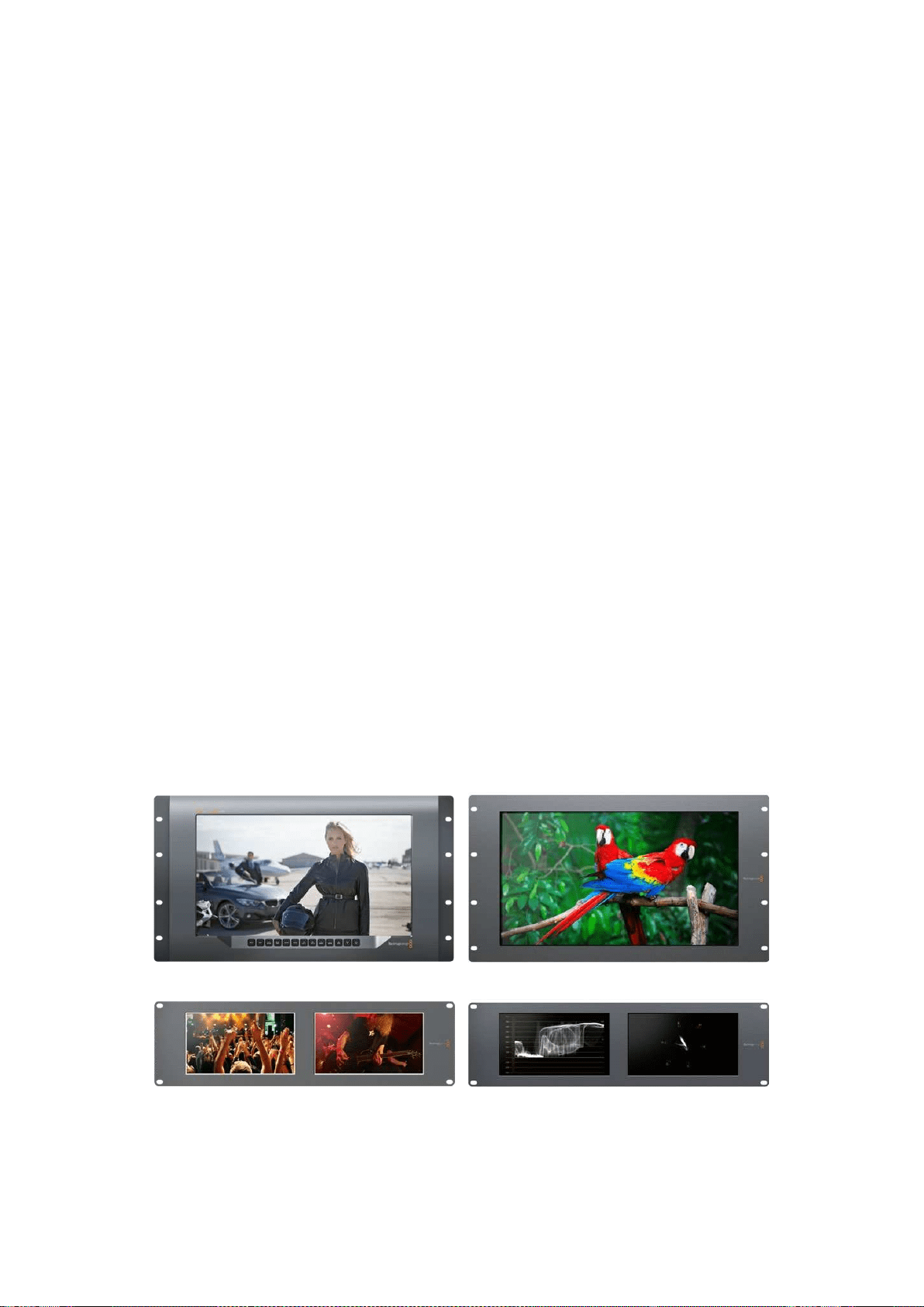
271Подготовка кработе
Подготовка кработе
SmartView иSmartScope
Мониторы SmartView превосходно подходят для размещения встойке соборудованием.
Чтобы приступить кработе, достаточно включить питание исоединить устройство
систочником SDI-сигнала.
Модель SmartView 4K имеет 15,6-дюймовый ЖК-дисплей, который обеспечивает вывод SD-,
HD- или Ultra HD-видео вразрешении 3840x2160. С помощью кнопок на передней панели
можно выбрать вход, настроить яркость экрана, проверить шум всинем канале, просмотреть
служебные данные иприменить 3D LUT-таблицу.
ЖК-экран SmartView HD размером 17дюймов идеально подходит для мониторинга сигнала
вразрешении Full HD.
SmartView Duo имеет два дисплея для одновременного вывода разных потоков. Например,
можно использовать комбинацию YUV 4:2:2 иRGB 4:4:4 или NTSC иPAL. В каждом случае
потребуется только подключить SDI-кабель ккаждому источнику изображения.
SmartScope Duo 4K имеет такой же набор функций, как SmartView Duo, но дополнительно
позволяет выводить форму сигнала, использовать вектороскоп идругие индикаторы для
мониторинга видео- иаудиосигнала вреальном времени. Кроме того, эта модель
поддерживает Ultra HD 4K.
SDI-интерфейс мониторов SmartView иSmartScope автоматически определяет формат
поступающего видео от SD иHD до 3G-SDI, втом числе 2K. Модель SmartView 4K
споддержкой 12G-SDI также позволяет работать сUltra HD, включая 2160p/60, а SmartScope
Duo 4K — сUltra HD 4K через 6G-SDI.
Для удаленной настройки нескольких мониторов SmartView иSmartScope содного
компьютера допускается их последовательное подключение через локальную сеть Ethernet.
В этом случае отпадает необходимость делать это виндивидуальном порядке
через USB-порт.
Все готово для начала работы! Подробнее о подключении SmartView иSmartScope,
настройке мониторов спомощью утилиты Blackmagic SmartView Setup исоединении
устройств по сети см. разделы ниже.
SmartView 4K SmartView HD
SmartView Duo SmartScope Duo 4K

272Подготовка кработе
Подключение источников видео
Мониторы SmartView иSmartScope оснащаются стандартными BNC-разъемами, которые
обеспечивают совместимость страдиционным SDI-оборудованием, втом числе
видеомикшерами, камерами, платами захвата, деками идисковыми рекордерами.
Вывод изображения
Для вывода изображения достаточно подключить питание исоединить источник сигнала
сSDI-входом. После этого оно появится на дисплее монитора. Устройство автоматически
определяет формат входящего видео на SDI исквозном интерфейсе
(SD, HD и2K, а также Ultra HD 4K при работе сSmartView 4K иSmartScope Duo 4K).
При отсутствии входящего сигнала подсветка устройства отключается.
Последовательное соединение мониторов
SmartView иSmartScope имеют независимый SDI-вход исквозной выход, что позволяет
выполнить последовательное подключение нескольких мониторов для передачи одного
итого же сигнала.
1 Включите питание на устройстве №1. Подключите источник видео кSDI-входу.
Изображение будет поступать на экран.
2 Включите питание на устройстве №2. С помощью SDI-кабеля соедините сквозной
выход устройства №1 сSDI-входом решения №2.
Количество подключаемых устройств не ограничено.
При выводе формы сигнала спомощью SmartScope Duo 4K можно подключить выход
монитора № 1 к монитору № 2 для проверки одного итого же изображения на
обоих дисплеях.
При выводе изображения можно менять настройки или выбирать индикаторы на SmartScope
Duo 4K спомощью утилиты Blackmagic SmartView Setup, а также загружать 3D LUT-таблицы
наBlackmagic SmartView 4K.
SmartView 4K SmartView HD
SmartView Duo SmartScope Duo 4K
Подключение ккомпьютеру
Для настройки монитора SmartView или SmartScope подключите его к ПК с помощью
USB-кабеля и установите утилиту Blackmagic SmartView Setup.
Порт USB также служит для обновления программного обеспечения, загруженного
свеб-сайта Blackmagic Design. Установка последней версии ПО позволяет расширить
функционал, улучшить совместимость с аппаратными средствами и гарантирует поддержку
дополнительных форматов и стандартов. Утилиту Blackmagic SmartView Setup можно
использовать на компьютерах с операционной системой macOS или Windows.
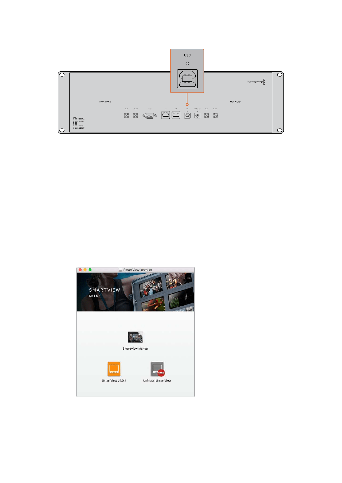
273Подготовка кработе
Установка утилиты Blackmagic SmartView Setup
Утилита Blackmagic SmartView Setup совместима с операционной системой macOS (версии
Sierra и High Sierra), а также Windows 8.1 и 10 (64-разрядная версия с последними пакетами
обновления). При необходимости установка допускается на несколько сетевых компьютеров.
Комплект поставки включает SD-карту с ПО, но мы рекомендуем использовать
последнююверсию, которую можно загрузить на нашем веб-сайте по адресу
www.blackmagicdesign.com/ru/support.
Установка на macOS
Дважды щелкните кнопкой мыши по значку мастера установки SmartView на SD-карте или
впапке загрузок. В разделе Applications (Приложения) будет создана новая папка SmartView,
содержащая утилиту SmartView Setup, деинсталлятор для удаления устаревших версий при
обновлении системы и различные документы, включая руководство пользователя.
Установка на Windows
В операционной среде Windows откройте SD-карту или загруженный zip-файл и щелкните
дважды по мастеру установки SmartView. Далее следуйте инструкциям на экране.
В операционной среде macOS запустите файл SmartView.dmg
с SD-карты либо из папки загруженных документов, затем
дважды щелкните по значку мастера установки SmartView
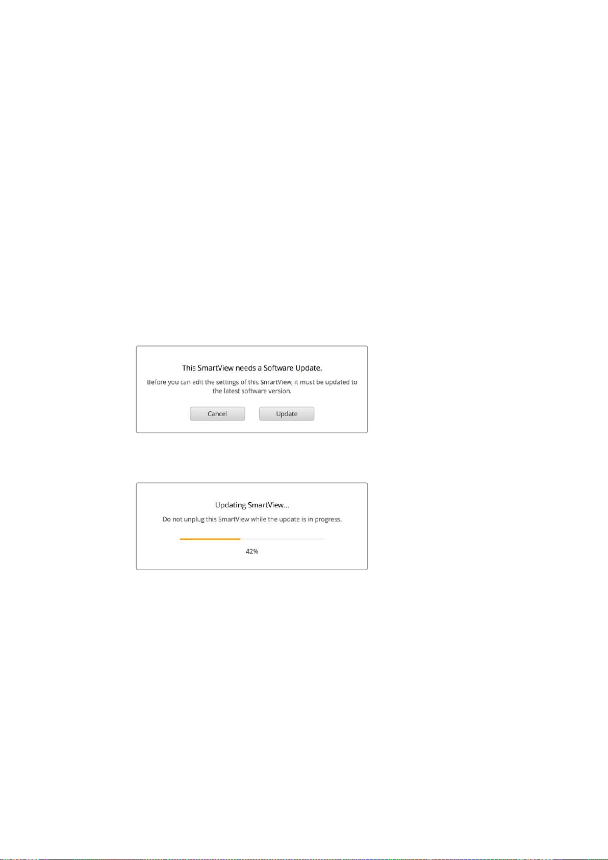
274Работа сутилитой Blackmagic MultiViewSetup
Работа сутилитой Blackmagic
MultiViewSetup
Обновление программного обеспечения
После завершения установки Blackmagic SmartView Setup щелкните по значку настроек под
названием монитора. Если используемая версия устарела, появится сообщение
спредложением обновить ПО SmartView или SmartScope. Для этого выполните описанные
ниже действия.
3 Соедините монитор SmartView или SmartScope скомпьютером через порт USB или
Ethernet изапустите утилиту Blackmagic SmartView Setup.
4 При появлении сообщения выберите Update. Процесс обновления занимает около
пяти минут.
5 По окончании обновления появится сообщение "This SmartView has been updated".
6 Выберите Close.
Если используется актуальная версия, откроется страница снастройками монитора.
Если необходимо обновить ПО, при запуске утилиты Blackmagic
SmartView Setup появится соответствующее сообщение
Процесс обновления занимает около пяти минут
Изменение настроек монитора
При запуске утилиты Blackmagic SmartView Setup будет выполнен поиск устройств SmartView
или SmartScope, подключенных через USB или Ethernet, сотображением результатов на
начальной странице SmartView Setup. При наличии двух или более мониторов для перехода
кнужному используют левую иправую стрелки по бокам начальной страницы. Если
устройство подключено через порт USB, рядом сего именем появится
соответствующий значок.
Чтобы изменить используемые параметры, выберите монитор инажмите на значок настроек
под именем монитора. Откроется соответствующая страница. После завершения настройки
нажмите кнопку Save, чтобы сохранить изменения ивернуться кначальной странице.
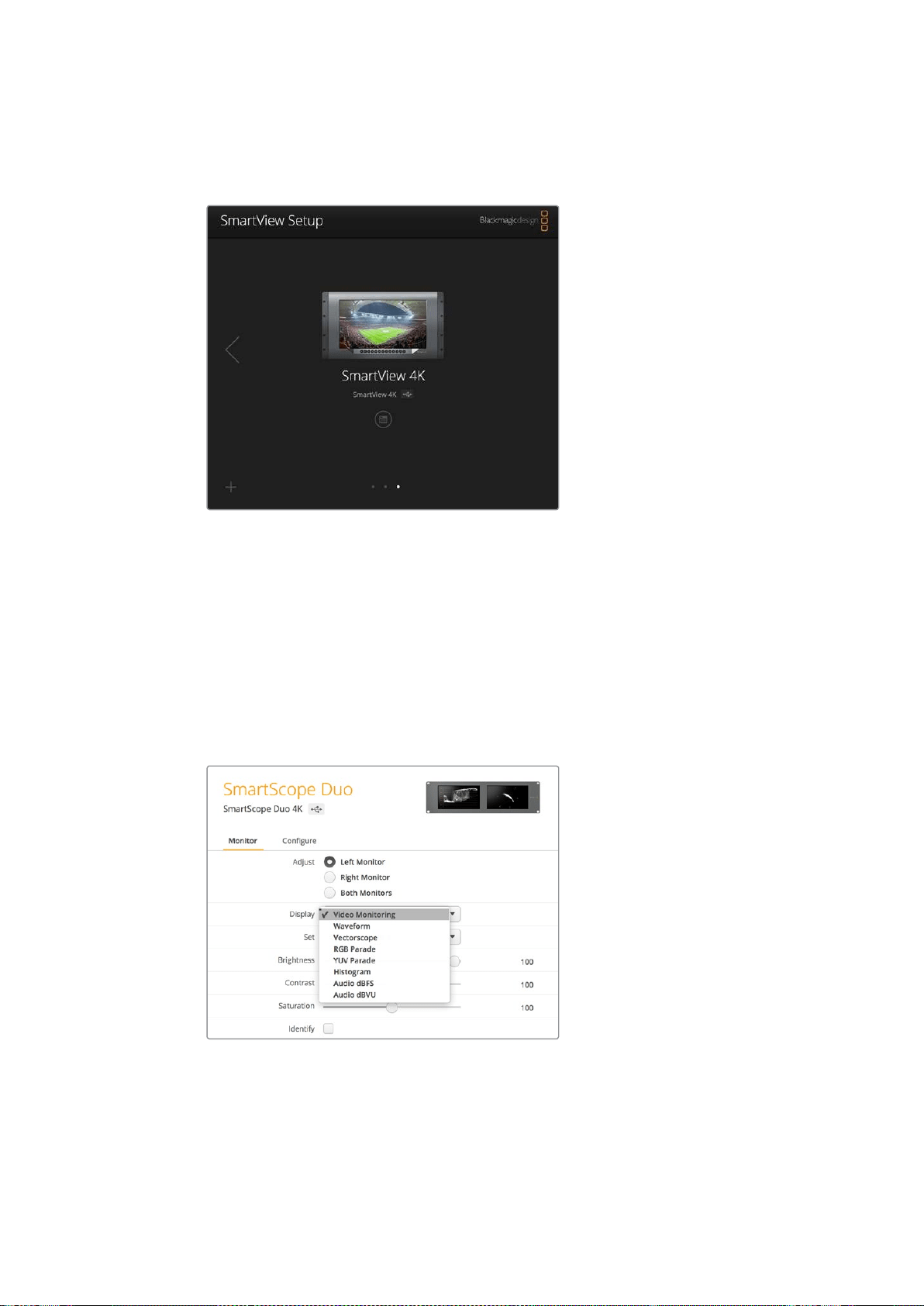
275Работа сутилитой Blackmagic MultiViewSetup
Подробнее о настройках на мониторах Blackmagic иих применении см. следующий раздел.
Информацию об установке сетевых параметров спомощью Blackmagic SmartView Setup
можно найти вразделе «Изменение сетевых настроек».
Утилита Blackmagic SmartView Setup автоматически выполняет
поиск устройств SmartView иSmartScope, подключенных по
сети или через порт USB. При обновлении программного
обеспечения убедитесь вналичии соединения смонитором
через нужный порт. При использовании USB-интерфейса
рядом сименем отображается соответствующий значок.
Настройки Monitor
Для выполнения настройки ивывода параметров монитор должен быть подключен через
Ethernet или USB. С помощью левой или правой стрелки на начальной странице SmartView
Setup перейдите кнужному устройству, затем под его именем выберите соответствующий
значок. На странице настроек автоматически отображается комбинация поддерживаемых
опций всоответствии свыбранной моделью.
В раскрывающемся меню Display выберите Video
Monitoring или нужный индикатор параметров
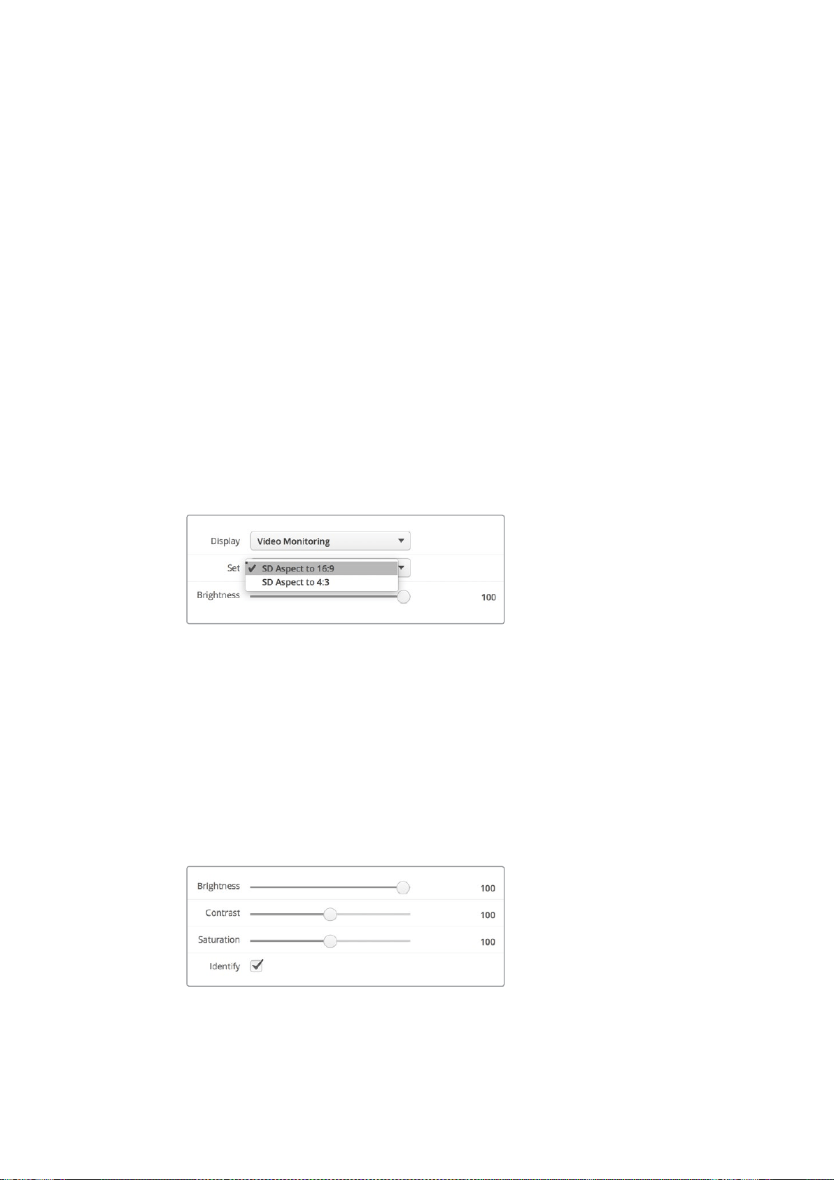
276Работа сутилитой Blackmagic MultiViewSetup
Настройка Adjust
При работе со SmartScope или SmartView Duo выберите нужный монитор: Left Monitor (левый),
Right Monitor (правый) или Both Monitors (оба). Если используется настройка Both Monitors,
любые изменения яркости, контрастности или насыщенности будут применяться кобоим
мониторам.
Настройка Display
При работе со SmartScope раскрывающееся меню Display содержит доступные индикаторы
параметров. Чтобы выводить изображение без индикации, выберите опцию Video Monitoring.
Настройка Set
При работе со SmartScope раскрывающееся меню Set позволяет выбрать пропорции кадра
(4:3 или 16:9) для вывода SD-видео, а для настройки Display можно использовать разные
индикаторы, втом числе Vectorscope, Audio dBFS иAudio dBVU.
Video Monitoring: вывод изображения спропорциями кадра 4:3 или 16:9. При
просмотре широкоэкранного анаморфного SD-видео выберите опцию 16:9,
востальных случаях — 4:3.
Vectorscope: выберите настройку 100% или 75% взависимости от используемого
тестового сигнала сцветными полосами.
Audio dBFS: выбор пары звуковых каналов для мониторинга фазы.
Audio dBVU: выбор пары звуковых каналов для мониторинга фазы.
При просмотре анаморфного SD-видео
выберите опцию SD Aspect to 16:9
Настройки Brightness, Contrast иSaturation
Изменение яркости, контрастности инасыщенности спомощью соответствующих слайдеров.
Настройка Identify
Поставьте флажок для настройки Identify, чтобы отображать белую рамку на дисплее того
устройства, которое выбрано вBlackmagic SmartView Setup. Это облегчает идентификацию,
если клокальной сети подключено несколько мониторов SmartView иSmartScope.
При использовании совместно снастройкой Both Monitors белая рамка отображается на
обоих дисплеях мониторов SmartView Duo иSmartScope Duo 4K.
Передвиньте слайдер вправо или влево для
изменения настроек Brightness, Contrast или Saturation.
Чтобы визуально идентифицировать выбранный
монитор, поставьте флажок для Identify.
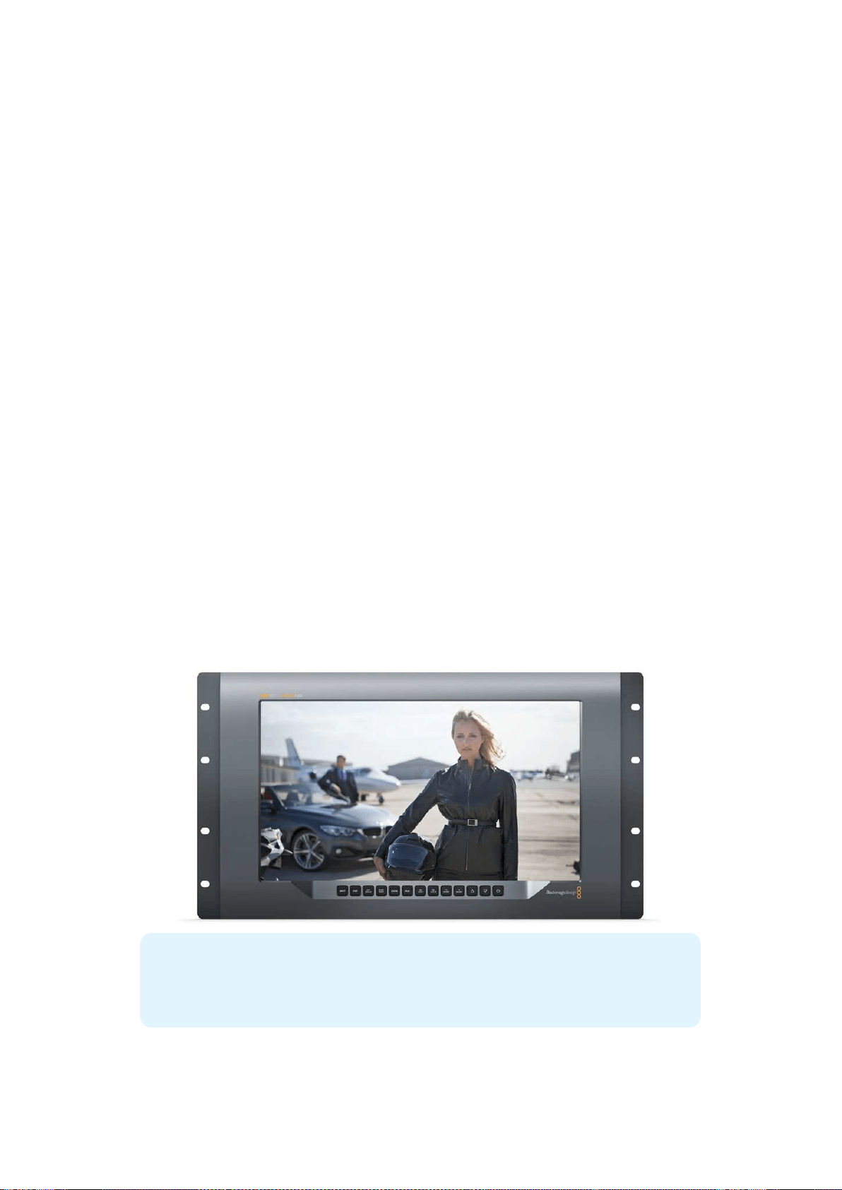
277Работа со SmartView 4K
Работа со SmartView 4K
Обзор Blackmagic SmartView 4K
Вещательный монитор SmartView 4K имеет интерфейс 12G-SDI для работы сUltra HD при
размере корпуса 6 RU. Эта модель поддерживает SD-, HD- и Ultra HD-форматы вплоть до
2160p/60, а яркий дисплей сширокой диагональю обеспечивает точную фокусировку
имониторинг цвета.
Модель SmartView 4K предназначена для использования встационарных имобильных
студиях. Боковое расположение интерфейсов ивозможность крепления по стандарту VESA
позволяют выполнять установку вусловиях ограниченного пространства, на стену или
поворотный кронштейн. SmartView 4K поддерживает два способа управления: спомощью
встроенной панели или удаленно через Ethernet при отсутствии локального доступа.
Два многоскоростных интерфейса 12G-SDI позволяют использовать разные источники
SDI-сигнала, а наличие гнезда для SFP-модуля по стандарту SMPTE обеспечивает передачу
видео по оптоволоконному соединению. Выход 12G-SDI дает возможность выводить
изображение на любое оборудование. Для сетевого соединения, удаленного управления
исквозного вывода при последовательном подключении кдругим мониторам есть два порта
Ethernet. Дополнительно предусмотрены разъемы для индикации состояния во время
эфирной работы ипорт USB для обновления программного обеспечения.
С помощью Blackmagic SmartView Setup можно загрузить созданные вDaVinci Resolve 3D
LUT-таблицы как файлы .cube, чтобы выводить изображение скамеры на SmartView 4K втом
виде, который максимально приближен кконечной версии после грейдинга. Два уровня
выделения контуров обеспечивают точную фокусировку, а совместимость систочниками
постоянного ипеременного тока позволяет подключать SmartView 4K косновной сети
энергоснабжения ик внешнему аккумулятору на площадке.
SmartView 4K является идеальным решением для мониторинга встудийных имобильных
условиях, обеспечивая вывод не только SD- иHD-, но иUltra HD-видео сразрешением
3840x2160 пикселей.
ПРИМЕЧАНИЕ. При подключении внешнего источника питания ко входу
постоянного тока убедитесь втом, что выходной разъем аккумулятора рассчитан на
мощность 24Вт снапряжением 12В.
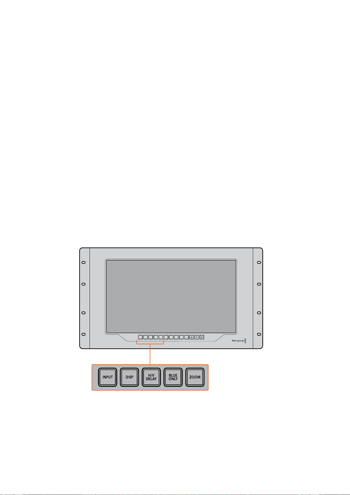
278Работа со SmartView 4K
Кнопки панели управления
Кнопки на панели управления служат для быстрого изменения настроек монитора
SmartView 4K.
INPUT
Служит для выбора входящего сигнала содного из двух интерфейсов 12G-SDI или
дополнительного оптического SFP-модуля. Если видео не поступает на выбранный вход,
отображается черный экран. При переключении между входами влевом верхнем углу
экранакратковременно выводится информация о формате поступающего сигнала.
DISP
Служит для настройки яркости ЖК-дисплея спомощью стрелок вверх ивниз. Нажмите
кнопку DISP еще раз для выхода.
H/V DELAY
Служит для вывода дополнительных данных, встроенных вSDI-видео. Чтобы увидеть данные,
расположенные горизонтально, нажмите кнопку один раз. Нажмите еще раз для показа
вертикальных данных, например скрытых субтитров.
BLUE ONLY
Если вцифровом видеосигнале есть шум, он заметен всинем канале. Чтобы проверить
наличие шума, нажмите кнопку BLUE ONLY. После этого будет выводиться черно-белое
изображение, которое также может служить для проверки фокуса камеры.
ZOOM
Служит для увеличения масштаба. Нажмите кнопку один раз, чтобы проверить фокусировку.
Для возврата кобычному размеру нажмите еще раз.
INPUT DISP
H/V
DELAY
3D
LUT 1
BLUE
ONLY
ZOOM PEAK
3D
LUT 2
H
MARK
V
MARK
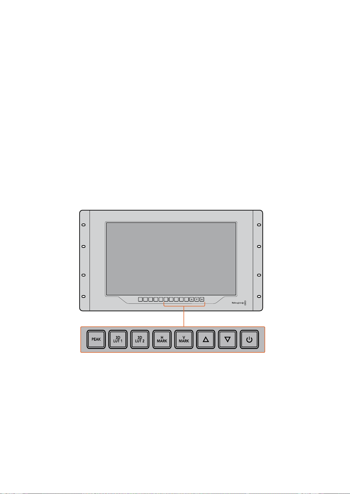
279Работа со SmartView 4K
PEAK
Служит для проверки фокусировки спомощью выделения контуров изображения. Вокруг
наиболее резких элементов будет отображаться зеленая кромка. Для этой функции
предусмотрены два уровня споследовательным переключением от одной настройки кдругой.
Когда зеленая кромка имеет наиболее отчетливый вид, фокус камеры настроен точно.
3D LUT 1 и3D LUT 2
Служат для вывода изображения сприменением пользовательских таблиц 3D LUT,
созданных вBlackmagic DaVinci Resolve (файлы срасширением .cube). Для включения
нажмите кнопку один раз. Чтобы отключить LUT-таблицы, нажмите еще раз. Подробнее
оработе с3D LUT-таблицами на SmartView 4K см. раздел «Загрузка 3D LUT спомощью
Blackmagic SmartView Setup».
H MARK иV MARK
Кнопки служат для вывода иредактирования маркеров кадра, спомощью которых можно
сохранять важную информацию или графику вбезопасной зоне экрана. Так как границы
кадра различаются взависимости от типа телевизора или дисплея, центральная область
изображения будет всегда оставаться видимой.
Для вывода горизонтальных или вертикальных маркеров кадра нажмите соответственно
HMARK или V MARK. Нажмите еще раз, чтобы отредактировать настройки. С помощью
стрелок вверх ивниз можно менять их позицию. Нажмите для подтверждения новых
координат. Чтобы отключить маркеры, нажмите кнопку еще раз.
INPUT DISP
H/V
DELAY
3D
LUT 1
BLUE
ONLY
ZOOM PEAK
3D
LUT 2
H
MARK
V
MARK
Стрелки вверх ивниз
Служат для изменения настроек (например, для увеличения или уменьшения яркости,
атакже при редактировании положения маркеров).
Питание
Нажмите кнопку питания, чтобы включить SmartView 4K. Для отключения устройства нажмите
кнопку еще раз.

280Работа со SmartView 4K
Загрузка 3D LUT спомощью Blackmagic SmartView Setup
SmartView 4K позволяет вести мониторинг спомощью 3D LUT-таблиц. Это дает возможность
настраивать устройство сиспользованием профессиональных средств калибровки или
просматривать материал втом виде, который максимально приближен кконечной версии
после грейдинга. 3D LUT-таблицы также помогают экспериментировать сразными цветовым
схемами. Для загрузки на SmartView 4K используют утилиту Blackmagic SmartView Setup.
Таккак монитор поддерживает файлы срасширением .cube, допускается работа
ссобственными таблицами, созданными вBlackmagic DaVinci Resolve. Подробнее о создании
файлов см. руководство по DaVinci Resolve.
Порядок загрузки 3D LUT-таблиц
1 Запустите утилиту Blackmagic SmartView Setup.
2 Нажмите кнопку Load для Load LUT 1. Откроется диалоговое окно для указания пути
кзагружаемой таблице. Выберите необходимый файл срасширением .cube, затем
нажмите Open.
3 Для просмотра загруженной таблицы выберите 3D LUT 1 на панели управления
SmartView 4K. Для отключения нажмите соответствующую кнопку еще раз.
Чтобы загрузить вторую LUT-таблицу, выполните аналогичные действия для 3D LUT 2.
Для загрузки 3D LUT-таблицы на SmartView 4K
используют утилиту Blackmagic SmartView Setup
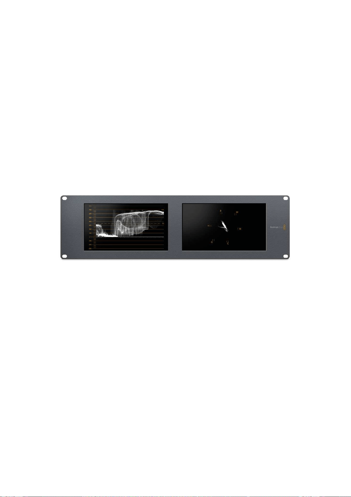
281Работа со SmartScope Duo 4K
Работа со SmartScope Duo 4K
Обзор Blackmagic SmartScope
Традиционные осциллографы, используемые впостпроизводстве ина телевидении,
являются очень дорогостоящими устройствами ипри этом способны выводить на экран
только по одному параметру за раз.
SmartScope Duo 4K имеет два дисплея, которые позволяют вреальном времени
контролировать различные параметры сигнала, при этом изменение способа представления
спомощью утилиты Blackmagic SmartView Setup сразу применяется кизображению на экране
устройства. Каждый входящий поток, поступающий через сквозной SDI-интерфейс, можно
направлять на любой из двух дисплеев: например, индикаторы сигнала — на правый, а само
изображение — на левый.
Индикаторы, отображаемые на SmartScope Duo 4K, можно выбрать спомощью утилиты
Blackmagic SmartView Setup. Для этого перейдите краскрывающемуся меню Display.
Подробнее о назначении каждого из индикаторов испособах их использования см.
разделы ниже.
С помощью Blackmagic SmartView Setup на дисплеи монитора BlackmagicSmartScope Duo 4K можно
выводить различные индикаторы
Мониторинг видео
Когда для настройки Display используется опция Video Monitoring, на экран выводится
поступающее на вход изображение.
Для SD-сигнала вменю Set можно выбрать пропорции кадра 4:3 или 16:9. Любые изменения
настроек яркости, контрастности или насыщенности можно сразу увидеть на дисплее. Они
применяются только для отображения на мониторе, но не затрагивают непосредственно
сам сигнал.
Один дисплей можно использовать для вывода видео, а другой — для отображения
индикаторов. Для этого соедините сквозной SDI-выход монитора №1 ивход монитора
№2спомощью короткого кабеля.
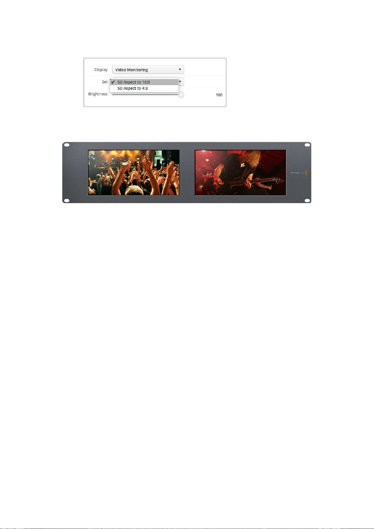
282Работа со SmartScope Duo 4K
В меню Set утилиты Blackmagic SmartView Setup для SD-видео
можно выбрать пропорции кадра 4:3 или 16:9. Для просмотра
анаморфного изображения используется вторая опция.
Опция Video Monitoring для настройки Display позволяет выводить изображение втаком же виде,
вкаком оно поступает на экран телевизора или монитора
Форма сигнала
Этот индикатор служит для отображения формы сигнала вцифровом виде ииспользуется
для мониторинга видео инастройки его уровня яркости.
В отличие от традиционных мониторов, которые способны работать только саналоговым
композитным видео встандартном разрешении, SmartScope Duo 4K поддерживает SD,
HDиUltra HD. Это позволяет вести полноценный контроль уровня яркости даже при работе
сформатами высокой четкости.
Для этого выберите опцию Waveform враскрывающемся меню Display утилиты Blackmagic
SmartView Setup. Чтобы не допустить засветки или затемнения, уровень яркости не должен
опускаться ниже 0% иподниматься выше 100%.
Форма сигнала — это графическое представление изображения, показывающее уровни
яркости сраспределением вграницах кадра. Например, если засвечена часть неба, это будет
заметно на соответствующем участке.
Вид формы сигнала зависит от съемочного материала. При мониторинге кадров свысокой
контрастностью полутона могут отсутствовать. На рисунке ниже показана форма сигнала
сравномерной экспозицией: левая часть соответствует темному участку, а область от центра
кправому краю кадра — более светлым зонам.
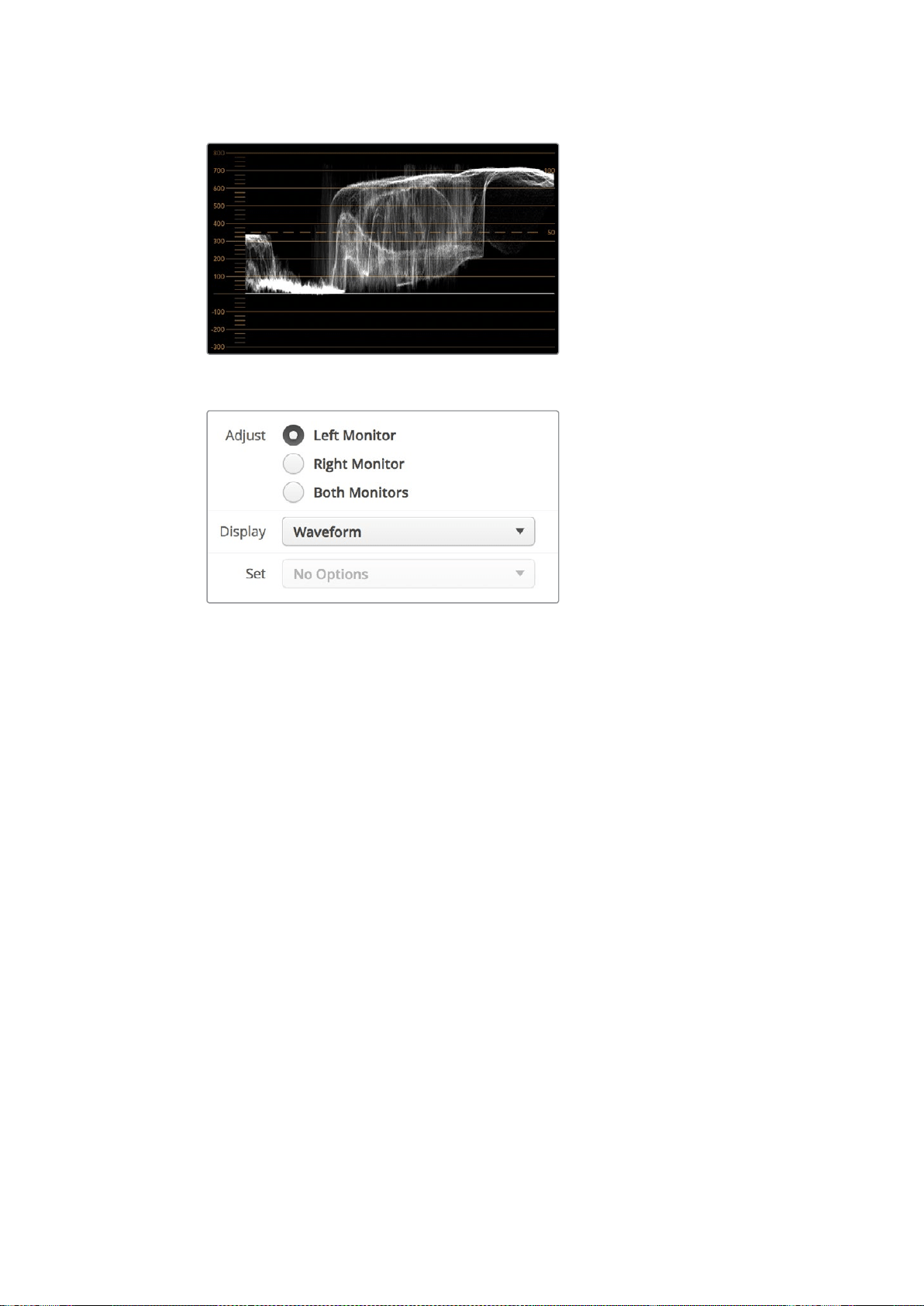
283Работа со SmartScope Duo 4K
Дисплей формы сигнала показывает уровни яркости
Чтобы увидеть параметры яркости сигнала, выберите
опцию Waveform для настройки Display
Вектороскоп
Этот индикатор позволяет получить информацию о цветах видеосигнала. Выберите 100% или
75% враскрывающемся меню Set взависимости от используемого тестового сигнала
сцветными полосами.
Иногда считают, что спомощью вектороскопа можно выявлять некорректные уровни
сигнала. Подобное мнение ошибочно, потому что для этого нужно видеть значения цветности
ияркости. Чтобы определить некорректные уровни, используется дисплей RGB Parade.
Цвета, приближенные кбелому или черному, не могут быть такими же насыщенными, как
более глубокие цвета, формирующие различные оттенки. Так как вектороскоп не показывает
значения яркости, его нельзя использовать только для выявления некорректных уровней.
Вектороскоп идеально подходит для проверки икоррекции цвета визображении,
полученном со старых аналоговых видеопленок. Для этого достаточно воспроизвести
нужный фрагмент, а затем скорректировать параметры цветности итона спомощью шкалы.
Вектороскоп будет незаменимым инструментом при выполнении цветокоррекции, потому что
он позволяет проверить баланс белого. Если изображение содержит какой-либо цветовой
оттенок, информация о нем будет смещаться от центра вектороскопа иможет иметь две
точки. Если всигнале используется гашение, то обычно вцентре диаграммы отображается
точка, потому что во время гашения видео представляет собой черное поле. Оно может
служить полезной контрольной точкой, спомощью которой легко установить отсутствие
информации о цвете.
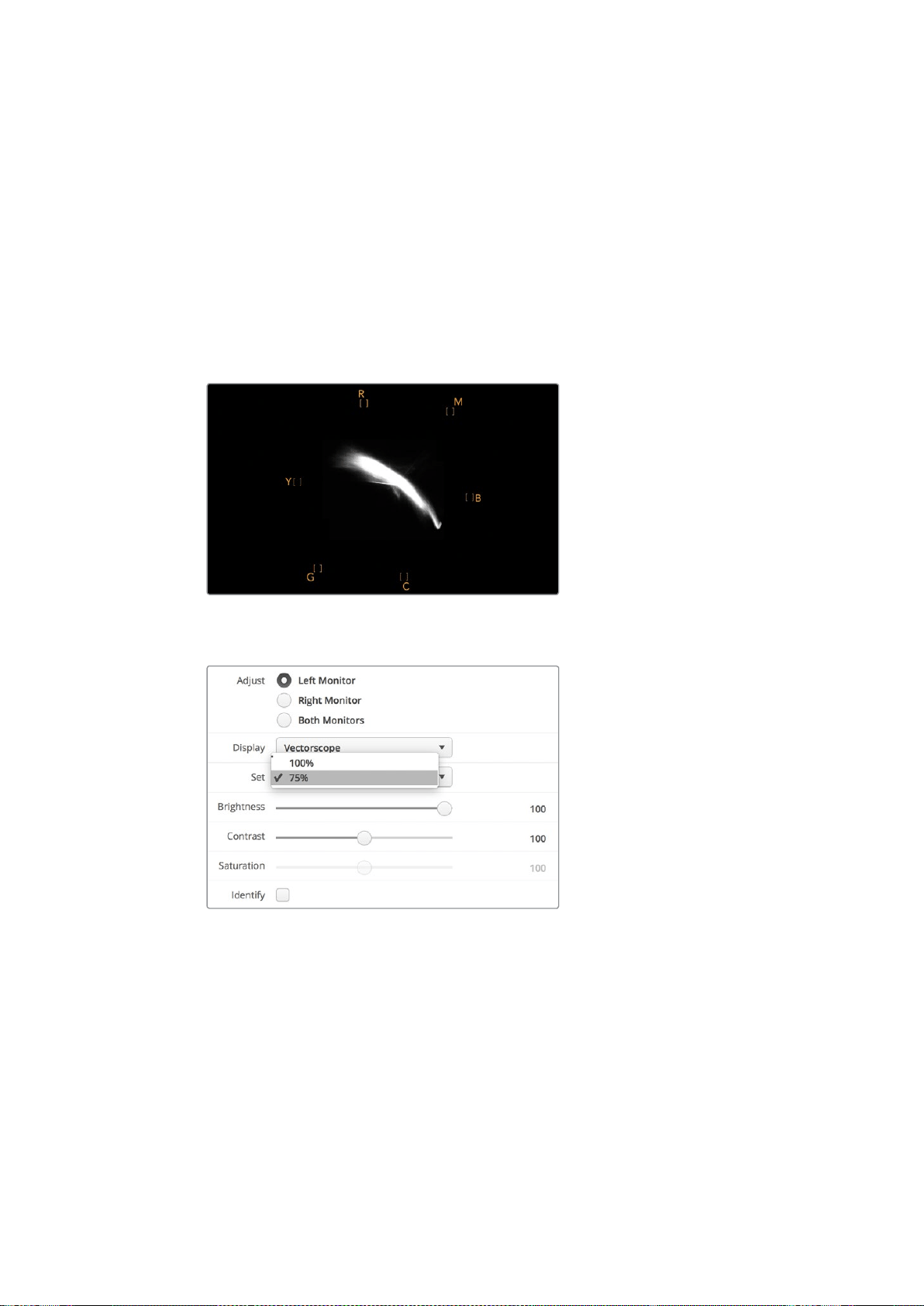
284Работа со SmartScope Duo 4K
Если изображение содержит какой-либо цветовой оттенок, информация о нем будет
смещаться от центра. Степень смещения зависит от интенсивности цветового оттенка
изатрагивает участки, отображающие как светлые, так итемные тона. Благодаря этому
вектороскоп можно использовать для удаления цветовых оттенков исохранения
правильного баланса белого.
Вектороскоп позволяет корректировать цвет без добавления нежелательных оттенков
вобластях света итени. Хотя баланс цвета можно контролировать спомощью дисплея RGB
Parade ивектороскопа, проблемы сэтим параметром проще отследить во втором случае.
При установке цвета человеческого лица параметр насыщенности обычно должен
соответствовать положению «10 часов» на вектороскопе. Это положение называется линией
«телесного тона» ипозволяет добиться такого цвета кожи, который будет выглядеть
естественным независимо от расовой принадлежности человека.
Линия «телесного тона» соответствует
положению «10 часов» на вектороскопе
Выберите 100% или 75% взависимости от используемого
тестового сигнала сцветными полосами
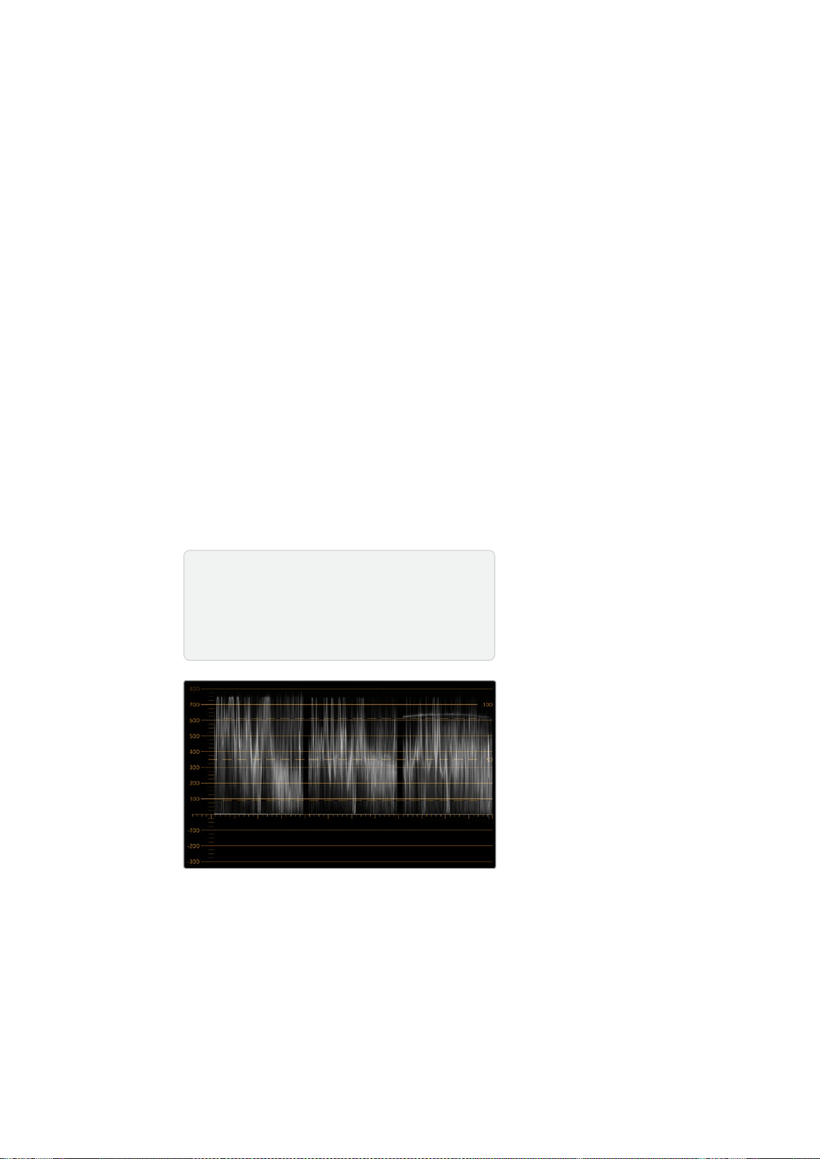
285Работа со SmartScope Duo 4K
Дисплей параметров
Дисплеи RGB Parade иYUV Parade позволяют получить информацию о некорректных уровнях
цвета иидеально подходят для грейдинга.
При выполнении цветокоррекции выберите RGB Parade враскрывающемся меню Display.
Дисплей RGB Parade отображает по отдельности полную шкалу красного, зеленого исинего
каналов. Когда изображение представлено втаком виде, проще контролировать цветовой
баланс вобластях света, полутона итени, а также удалять нежелательную тонировку.
Во время выполнения цветокоррекции важно сохранять сигнал взаданных границах.
Приувеличении его уровня нужно следить за тем, чтобы он не выходил за пределы,
установленные для параметров RGB. Независимо от используемого оборудования, монитор
SmartScope Duo 4K позволяет всегда видеть некорректные уровни RGB-изображения.
Некорректные уровни могут проявляться как засветка или затемнение изображения.
Внекоторых системах грейдинга уровень черного можно уменьшить ниже 0%. При наличии
некорректных уровней черного для их компенсации увеличьте значение Lift или Gain,
ноубедитесь втом, что уровень сигнала не превышает 100%, чтобы не допустить засветки
вобластях света.
Для проверки уровней YUV выберите враскрывающемся меню Display опцию YUV Parade.
Вэтом случае параметры яркости будут отделены от цвета подобно тому, как принято
втелевещании. Левая часть дисплея соответствует яркости, а второй итретий индикаторы
содержат информацию о цвете. YUV Parade позволяет выполнять калибровку цвета по
тестовым шаблонам для корректной передачи вещательного сигнала на экраны телевизоров.
Благодаря цветокоррекции можно получить максимально качественное изображение
ссохранением уровней сигнала взаданных границах.
RGB Parade
Термины цветокоррекции
Тени – темные тона.
Гамма – средние тона.
Света – светлые тона.

286Работа со SmartScope Duo 4K
YUV Parade
В раскрывающемся меню Display выберите
дисплей RGB Parade или YUV Parade
Гистограмма
С гистограммой чаще всего имеют дело графические дизайнеры иоператоры камер.
Онапоказывает распределение элементов изображения от белого кчерному цвету
ипозволяет увидеть недостаточную или избыточную экспозицию. С ее помощью можно
также контролировать изменение видео при корректировке средних тонов.
В левой части дисплея сосредоточена информация о темных тонах, вправой части —
осветлых. Как правило, она должна находиться винтервале от 0% до 100%. При
недостаточной или избыточной экспозиции информация об изображении выходит за эти
крайние точки. Дефекты экспозиции осложняют обработку изображения иего
цветокоррекцию на этапе постпроизводства, поэтому во время съемки важно следить за тем,
чтобы гистограмма не опускалась ниже крайней левой точки ине поднималась выше крайней
правой точки. В этом случае колорист будет иметь больше свободы при выполнении
грейдинга.
Когда во время цветокоррекции применяют засветку или затемнение, гистограмма
отображает этот эффект ипоказывает степень недостаточной или избыточной экспозиции.
Средние тона позволяют добиться сходного эффекта ипри этом сохранить больше деталей.
Гистограмма не подходит для проверки некорректных уровней, хотя дает возможность
увидеть недопустимые значения светлых итемных тонов. Так как она не отображает цвета,
некорректные уровни нельзя увидеть даже при их наличии. Для выявления таких уровней
нужно использовать индикатор RGB Parade, который показывает как цвет, так ияркость
элементов видеосигнала.

287Работа со SmartScope Duo 4K
Гистограмма показывает распределение элементов
изображения от белого кчерному цвету
В раскрывающемся меню Display выберите Histogram
Уровень звука
Этот индикатор показывает уровень звука, встроенного вSDI-видео. Из поступающего
потока извлекается до 16каналов аудио, которые отображаются врежиме dBVU или dBFS.
Индикатор VU показывает средние уровни сигнала, прост вприменении ичаще встречается
на оборудовании предыдущего поколения. Он откалиброван всоответствии
срекомендациями SMPTE (тональный тест-сигнал 1 кГц имеет значение -20 dBFS).
dBFS представляет собой индикатор всего цифрового аудиосигнала иобычно используется
всовременном оборудовании.
Аудиометр вправой части экрана предназначен для мониторинга двух каналов звука,
которые выбирают враскрывающемся меню Set (Phase scope to 1 & 2, Phase scope to 3 & 4
ит.д.). Он отображает моно- или стереодорожку вдвухмерной системе координат
ипозволяет выявлять нарушение баланса инесовпадение по фазе. Монодорожка будет
представлена ввиде единичной вертикальной линии. Если показана горизонтальная линия,
имеет место сдвиг фазы, что может привести кпотере сигнала при передаче на другое
оборудование. Несовпадение по фазе — одна из самых частых технических проблем при
использовании большого количества соединений.
При мониторинге стереодорожки сигнал имеет округлую форму, отображая разницу между
правым илевым аудиоканалами. Чем больше стереозвука содержится ваудиодорожке,
темболее закругленным будет изображение на экране. Если аудио содержит минимальное
количество стереоэффектов, форма сигнала вытягивается вдоль вертикальной линии.

288Подключение клокальной сети
Речь обычно отображается как вертикальная линия, а музыка со стереоэффектами —
какэллипс или круг. Это объясняется тем, что аудиометр показывает монодорожку как L+R
навертикальной оси, а стереодорожку — ввиде разницы L-R на горизонтальной оси.
Индикатор уровня звука показывает
пиковые значения ибаланс аудио
В раскрывающемся меню Set выберите
пару аудиоканалов для мониторинга
Подключение клокальной сети
Подключив SmartView или SmartScope клокальной сети, можно выполнить удаленную
настройку сразу нескольких мониторов.
Хотя SmartView иSmartScope позволяют выводить видео без предварительной настройки,
сначала нужно установить сетевые параметры. Это можно сделать только путем прямого
подключения оборудования ккомпьютеру через порт USB.
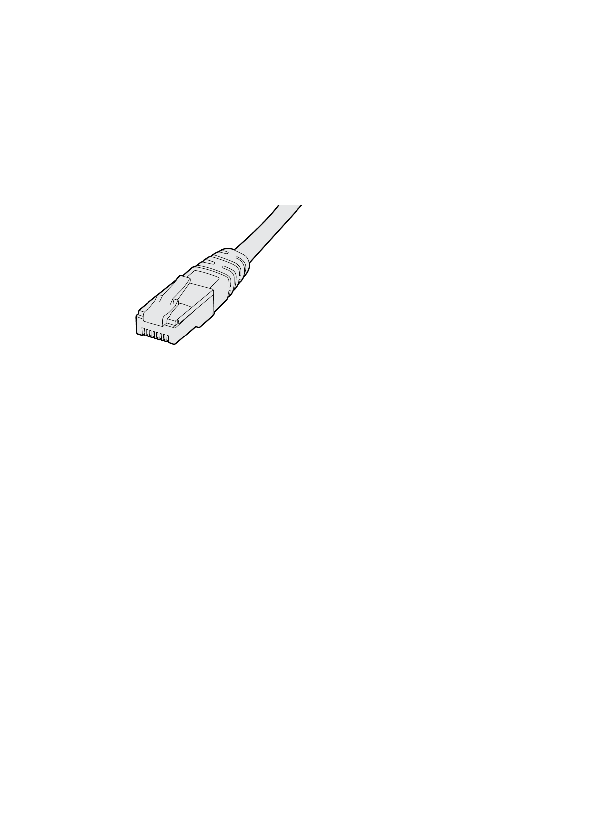
289Подключение клокальной сети
Подключение ксети Ethernet
Удаленная настройка монитора выполняется путем прямого подключения ккомпьютеру по
локальной сети Ethernet, при этом использование сетевого коммутатора не требуется.
Дополнительные устройства можно соединить между собой по цепочке через порт Ethernet.
На каждое из них должно поступать питание.
Когда мониторы подключают без указания IP-адресов или локальная сеть отсутствует,
соедините SmartView или SmartScope напрямую спортом Ethernet на компьютере. В этом
случае можно обойтись без кабеля для использования ссетевым коммутатором.
Подключение через Ethernet
Сетевой коммутатор
При работе снесколькими мониторами SmartView или SmartScope влокальной сети только
один из них нужно соединить ссетевым коммутатором, а остальные можно подключить
последовательным способом через сквозной порт Ethernet. Питание должно подаваться на
все устройства вцепочке.
Соединение ссетевым коммутатором позволяет изменить настройки устройства слюбого
локального компьютера. Если сеть имеет беспроводную точку доступа, это можно сделать
через Wi-Fi спомощью ноутбука (операционная система Mac или Windows).
Ниже описан порядок подключения SmartView иSmartScope клокальной сети сIP-адресами.
1 Соедините устройство споставляемым блоком питания ивключите его.
2 Для соединения ссетевым коммутатором или при подключении напрямую
ккомпьютеру используйте стандартный кабель Ethernet сразъемом RJ45.
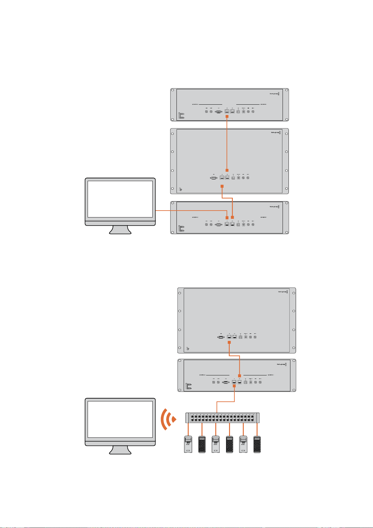
290Подключение клокальной сети
Схема соединения всети Ethernet
Монитор можно подключить напрямую ккомпьютеру через порт Ethernet без использования
сетевого коммутатора. При последовательном соединении питание должно подаваться на
все устройства вцепочке.
SmartScope 4KDuo
Схема соединения скоммутатором всети Ethernet
При работе снесколькими мониторами влокальной сети только один из них нужно соединить
ссетевым коммутатором, а остальные можно подключить последовательным способом.
Питание должно поступать на все устройства.
SmartScope 4KDuo
Сетевой коммутатор
Ethernet
Компьютер-
клиент

291Изменение сетевых настроек
Изменение сетевых настроек
Сетевые параметры
Имя устройства
Для удобства идентификации можно изменить имена мониторов SmartView иSmartScope
(например, «Внестудийные камеры 1 и2», «Многооконный выход», «4K-видео» ит. д.).
Чтобы изменить имя устройства, убедитесь, что оно подключено через порт Ethernet или
USB. Откройте утилиту Blackmagic SmartView Setup ивыберите значок настроек под именем
монитора. Перейдите кразделу сетевых параметров ив строке Name раздела Details
укажите новое имя. При использовании недопустимого значения появится соответствующее
предупреждение. Если формат имени корректен, рядом сним будет отображаться флажок
зеленого цвета. Нажмите Enter (ввод) склавиатуры, чтобы подтвердить изменение.
Сетевые параметры
Чтобы изменить сетевые настройки спомощью утилиты Blackmagic SmartView Setup, монитор
должен быть подключен ккомпьютеру через порт USB. Порт Ethernet не предназначен для
этих целей.
По умолчанию для автоматического получения сетевого IP-адреса используется
настройка DHCP.
Чтобы получить DHCP-адрес в случае отсутствия DHCP-сервера, можно активировать
функцию Internet Sharing (на macOS) или Internet Connection Sharing (ICS) (Windows 8.1 или
Windows 10). Это поможет избежать ввода статичных IP-адресов вручную, в том числе без
подключения компьютера к Интернету. Подробнее см. разделы справки в ОС macOS,
Windows 8.1 или Windows 10.
Если DHCP не используется, выберите Static IP. При установке статичного IP-адреса
обратитесь за помощью ксистемному администратору. Каждому устройству SmartView или
SmartScope необходимо присвоить уникальный IP-адрес иобщий адрес для Subnet Mask.
Настройки по умолчанию вполе Gateway менять не нужно, если монитор не подключен
ксетевому шлюзу (например, к интернет-коммутатору).
Если мониторы SmartView иSmartScope не обнаружены, скорее всего им не были присвоены
IP-адреса спомощью протокола DHCP. В этом случае необходимо ввести соответствующие
сетевые настройки вручную в описанном ниже порядке.
1 Подключите монитор SmartView или SmartScope ккомпьютеру через порт USB
иоткройте утилиту Blackmagic SmartView Setup.
2 Подключенный монитор будет автоматически распознан ипоказан на начальной
странице Blackmagic SmartView Setup, а рядом сего именем появится значок USB.
3 Измените сетевые настройки монитора.
4 Повторите описанные выше действия для других мониторов, которым не были
присвоены IP-адреса спомощью протокола DHCP.

292Изменение сетевых настроек
Значок USB рядом сименем монитора указывает на то, что он
подключен ккомпьютеру через порт USB. Это соединение
используют для изменения сетевых настроек монитора.
Сетевые настройки можно установить двумя
способами (DHCP или Static IP). Для их изменения
используется подключение через порт USB.
Добавление монитора
Если SmartView или SmartScope Duo 4Kне отображается на главной странице утилиты
SmartView Setup, но известен IP-адрес устройства, его можно добавить вручную. Для этого
выполните описанные ниже действия.
1 Убедитесь, что устройство подключено через порт Ethernet. Выберите знак плюса
внижнем левом углу экрана. Откроется диалоговое окно для добавления монитора.
2 Введите IP-адрес устройства инажмите Add.
3 Будет проверено наличие подключенных устройств идобавлен новый монитор,
информация о котором появится на главной странице утилиты SmartView Setup.
Чтобыувидеть его, нажмите на правую стрелку.
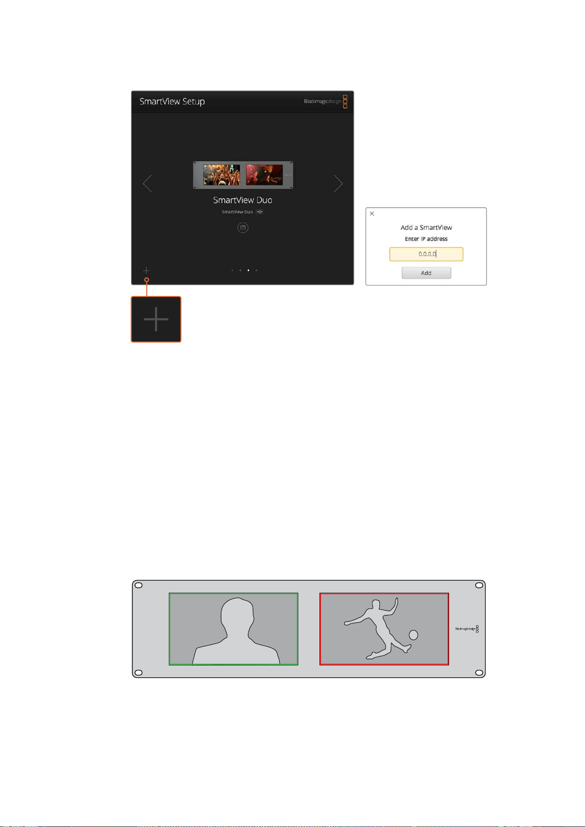
293Индикация состояния
Чтобы добавить монитор SmartView или SmartScope ксписку
подключенных устройств, выберите знак плюса ивведите IP-адрес
Индикация состояния
Контакты порта Tally-индикации
Если вы не используете индикацию состояния при работе со SmartView или SmartScope,
перейдите кследующему разделу.
Всемониторы SmartView иSmartScope поддерживают индикацию состояния, которая
отображается как красная, зеленая или синяя рамка (в эфире, предварительный просмотр
или запись соответственно).
9-контактный разъем типа D-sub может принимать сигналы замыкания свидеомикшера
исистем автоматизации. Подробнее см. схему подключения иразводки.
Схема сописанием 9-контактного разъема типа D находится на задней панели устройства.
На экранах SmartView Duo для индикации используются рамки зеленого икрасного цвета

294Регулировка угла обзора
SmartView Duo и SmartScope Duo 4K
Назначение контактов
Контакт Функция
1 Монитор 1, рамка красного цвета
2 Монитор 1, рамка зеленого цвета
3 Монитор 1, рамка синего цвета
4 Земля
5 Земля
6 Земля
7 Монитор 2, рамка красного цвета
8 Монитор 2, рамка зеленого цвета
9 Монитор 2, рамка синего цвета
SmartView HD и SmartView 4K
Назначение контактов
Контакт Функция
1 Красный
2 Зеленый
3 Синий
4 Земля
5 4 3 2 1
9
8
7 6
Порт Tally-индикации на SmartView
Регулировка угла обзора
При размещении мониторов SmartView Duo, SmartView HD иSmartScope встойке
соборудованием можно перевернуть устройство, чтобы получить оптимальный угол обзора.
Вэтом случае ориентация выводимого на экраны изображения поменяется автоматически.
Чтобы снять лицевую панель иустановить ее обратно, понадобится отвертка Pozidriv 2. Это
простая процедура, не требующая разборки корпуса.
Ниже описан порядок снятия иобратной установки лицевой панели для сохранения логотипа
Blackmagic Design висходном положении. Для этого понадобится отвертка Pozidriv 2.
1 Открутите винты со всех четырех сторон лицевой панели. Модели SmartView Duo
иSmartScope Duo 4K имеют по 10винтов, SmartView HD —18.
2 Приподнимите панель иснимите ее, как показано на рисунке.
3 Переверните панель.
4 Установите панель обратно.
5 Закрепите панель на корпусе спомощью винтов.
Теперь устройство готово кустановке встойку. После этого изображение будет выводиться
снужной ориентацией без регулировки спомощью внешних органов управления.


296Информация для разработчиков
Информация для разработчиков
Developing Custom Software Using Blackmagic Design Hardware
The Blackmagic SmartView Ethernet Protocol allows developers to remotely control Blackmagic
SmartView and SmartScope hardware with their own custom software. The Blackmagic SmartView
Ethernet Protocol is a text-based status and control protocol.
Downloading the Free SmartView EthernetProtocol
The Blackmagic SmartView Ethernet Protocol is free. It is included in this SmartView & SmartScope
manual and can be downloaded from www.blackmagicdesign.com/ru/support
Joining the Blackmagic Design Developer List
The Blackmagic Developer mailing list is designed for technical questions regarding technologies
used by Blackmagic Design, e.g., QuickTime, Core Media, DirectShow, codecs, APIs, SDKs, etc.
Thefree mailing list is a forum where developers can discuss ideas and problems with other
developers. Any subscriber may reply and the Blackmagic Design engineers may also
respond when appropriate. You can subscribe to the mailing list at:
http://lists.blackmagicdesign.com/mailman/listinfo/bmd-developer
In some cases, we might request a brief outline of the software you are developing if it is not
immediately obvious from your domain name that your organization develops video software.
Pleasedon’t take offence as we’re simply trying to keep the list free of spam and viruses as well
asend-user customers asking non-development questions, employment agents or sales people
trying to promote products on the list. The list is just for developers.
Contacting Blackmagic Design DeveloperAssistance
You can also contact us via developer@blackmagicdesign.com if you have any developer related
questions or wish to ask questions off the list.
Blackmagic 2K Format – Overview
Blackmagic Design products support 3G-SDI video, which allows twice the data rate of traditional
HD-SDI video. We thought it would be a really nice idea to add 2K film support, via 3G-SDI technology,
so we could simplify feature film workflows. With the popularity of Blackmagic Design editing systems
worldwide, now thousands of people can benefit from a feature film workflow revolution.
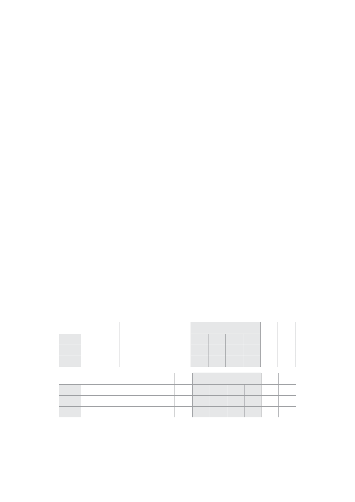
297Информация для разработчиков
This information includes everything product developers need to know for building native 2K SDI
equipment. Of course, all Blackmagic products can be updated, so if the television industry adopts
an alternative SDI-based film standard, we can add support for that too!
Frame Structure
Transmitted at 23.98, 24 or 25 frames per second as a Progressive Segmented Frame.
Active video is 2048 pixels wide by 1556 lines deep.
Total lines per frame : 1650
Active words per line are 1535. One word consists of a 10-bit sample for each of the
four data streams, i.e., a total of 40 bits. See the diagram named Blackmagic 2K Format
- Data Stream Format.
Total active lines : 1556
Total words per line : 1875 for 23.98/24Hz and 1800 for 25Hz.
Fields per frame : 2, 825 lines each
Active lines located on lines 16-793 (field 1) and 841-1618 (field 2).
Transport Structure
Based on SMPTE 372M Dual Link mapping and SMPTE 425M-B support for mapping SMPTE
372M into a single 3 Gb/s link.
Timing reference signals, line number and line CRC insertion is the same as above.
During active video, 10-bit Red, Green and Blue data is sent in the following sequence:
Optional ancillary data is inserted into both virtual interfaces.
At present, only audio data is included: as per standard HD audio insertion (SMPTE S299M)
the audio data packets are carried on data stream two and audio control packets are carried
on data stream one.
Data stream 1: Green_1, Green_2, Green_3, Green_5...Green_2047
Data stream 2: Blue_1, Blue_2, Green_4, Blue_5...Green_2048.
Data stream 3: Red_1, Blue_3, Blue_4, Red_5...Blue_2048.
Data stream 4: Red_2, Red_3, Red_4, Red_6...Red_2048.
Blackmagic 2K Format – Vertical Timing Reference
This diagram shows the vertical timing details with line numbers and Field, Vertical and Horizontal
bits for the Timing Reference Signal codes.
Field 1 Active
F 1 0 0 0 0 0 0 0 0 0 0 0
V 1 1 1 1 1 1 0 0 0 0 1 1
LINE # 1650 1 2 ... 14 15 16 ... 792 793 ... 825
Field 2 Active
F 0 1 1 1 1 1 1 1 1 1 1 1
V 1 1 1 1 1 1 0 0 0 0 1 1
LINE # 825 826 827 ... 839 840 841 ... 1617 1618 ... 1650
298Информация для разработчиков
Blackmagic 2K Format – Data Stream Format
This diagram shows the data stream formats around the optional ancillary data section of the
horizontal line. Note that each active pixel takes up three samples.
Data Stream 1
G2041
G2042
G2043
G2045
G2046
G2047
EAV(3FFh)
EAV(000h)
EAV(000h)
EAV(XYZh)
LN0
LN1
CRC0
CRC1
ANC/Audio Data
SAV(3FFh)
SAV(000h)
SAV(000h)
SAV(XYZh)
G1
G2
G3
G5
Data Stream 2
B2041
B2042
G2044
B2045
B2046
G2048
EAV(3FFh)
EAV(000h)
EAV(000h)
EAV(XYZh)
LN0
LN1
CRC0
CRC1
ANC/Audio Data
SAV(3FFh)
SAV(000h)
SAV(000h)
SAV(XYZh)
B1
B2
G4
B5
Data Stream 3
R2041
B2043
B2044
R2045
B2047
B2048
EAV(3FFh)
EAV(000h)
EAV(000h)
EAV(XYZh)
LN0
LN1
CRC0
CRC1
040
…
040
SAV(3FFh)
SAV(000h)
SAV(000h)
SAV(XYZh)
R1
B3
B4
R5
Data Stream 4
R2042
R2043
R2044
R2046
R2047
R2048
EAV(3FFh)
EAV(000h)
EAV(000h)
EAV(XYZh)
LN0
LN1
CRC0
CRC1
200
…
200
SAV(3FFh)
SAV(000h)
SAV(000h)
SAV(XYZh)
R2
R3
R4
R6
Word#
23.98/24 PsF
1870
1871
1872
1873
1874
1875
1
2
3
4
5
6
7
8
9
…
335
336
337
338
339
340
341
342
343
Word#
25 PsF
1795
1796
1797
1798
1799
1800
1
2
3
4
5
6
7
8
9
…
260
261
262
263
264
265
266
267
268

299Информация для разработчиков
Blackmagic SmartView Ethernet Protocol v1.3
Summary
The Blackmagic SmartView Ethernet Protocol is a text-based status and control protocol, very similar
in structure to the Videohub protocol, that is accessed by connecting to TCP port 9992 on a
SmartView or SmartScope device.
Upon connection, the SmartView or SmartScope device sends a complete dump of the state
of the device. After the initial dump, state changes are sent asynchronously.
The device sends information in blocks which have an identifying header, followed by a colon.
Ablock can span multiple lines and is terminated by a blank line.
To be resilient to future protocol changes, clients should ignore blocks they do not recognize, up to
the trailing blank line. Within recognized blocks, clients should ignore lines they do not recognize.
Version 1.3 of the Blackmagic SmartView Ethernet
Protocol was released with SmartView 1.3 software.
Protocol Preamble
The first block sent by the SmartView Server is always the protocol preamble:
PROTOCOL PREAMBLE:↵
Version: 1.3 ↵
↵
The version field indicates the protocol version. When the protocol is changed in a compatible way,
the minor version number will be updated. If incompatible changes are made, the major version
number will be updated.
Device Information
The next block contains general information about the connected SmartView or SmartScope device.
SMARTVIEW DEVICE:↵
Model: SmartView Duo↵
Hostname: stagefront.studio.example.com↵
Name: StageFront↵
Mo nitor s: 2↵
Inverted: false↵
↵
This example shows the output for a SmartView Duo device, which has two LCDs.
TheINVERTEDflag indicates whether the device has detected that it has been mounted in an
inverted configuration to optimize LCD viewing angle.
Legend
↵ carriage return
… and so on

300Информация для разработчиков
Network Configuration
The next block shows the TCP/IP networking configuration:
NETWORK:↵
Dynamic IP: true↵
Static address: 192.168.2.2↵
St atic netm as k: 255.255.255.0↵
St atic gatew ay: 192.168.2.1↵
C u rr e nt ad d r e ss: 192.168.1.101↵
C u rr e nt netm a sk: 255.255.255.0↵
C u rr e nt g ate w ay: 192.168.1.1↵
↵
The network settings prefixed with CURRENT show the active TCP/IP settings, and are read-only.
The CURRENT settings reflect either the DHCP or Static configuration, depending on the
DYNAMIC IP flag.
Changing Networking Settings
The network can be configured to use either DHCP or a static configuration. To enable DHCP:
NETWORK:↵
Dynamic IP: true↵
↵
To set a fixed IP address, supply all static parameters, thus:
NETWORK:↵
Dynamic IP: false↵
Static address: 192.168.2.2↵
St atic netm as k: 255.255.255.0↵
St atic gatew ay: 192.168.2.1↵
↵
The parameters with the CURRENT prefix are read-only, and show the active configuration,
regardless of the static or dynamic setting.
Changing the device name, or any network settings, will cause the IP connection to be dropped.
Thedevice will restart its networking and advertise its new name on the network.
Changing Monitor Settings
The display settings for each monitor are specified individually. One or more parameters can be
modified at the same time and multiple settings can be supplied in one block.
The valid range for numeric values is 0-255. The CONTRAST and SATURATION properties are
zero-centered, so the normal value is 127, such that the displayed picture is the same as the original.
A value greater than 127 in either channel will cause the contrast or saturation to be increased,
andsimilarly a value less than 127 will cause a decrease.
For example, to set the brightness to 50% and desaturate the image to Black & White:
MONITOR A:↵
Brightness: 127↵
Saturation: 0↵
↵

301Информация для разработчиков
Displaying SD in 16:9
The following command sets standard definition video to display in 16:9:
MONITOR A:↵
WidescreenSD: ON↵
Displaying SD in 4:3
The following command sets standard definition video to display in 4:3:
MONITOR A:↵
WidescreenSD: OFF↵
Identification and Tally Settings
The Identify flag is transient, and will cause a white border to be displayed around the entire picture
for a duration of 15 seconds, after which it will be reset. This feature is primarily aimed at identifying
which monitor is currently being configured when it is mounted in a rack comprising multiple units.
To turn on:
MONITOR A:↵
Ide ntify: tr u e↵
↵
The IDENTIFY border will temporarily override any other border setting in effect.
The BORDER property can be used to programmatically set the soft Tally colored borders to one
ofthe primary colors: RED, GREEN, BLUE, WHITE or NONE. This setting can be overridden by the
electrical Tally signals at the DB-9 input on the device itself. For example, to set the soft
Tally to green:
MONITOR B:↵
Border: green↵
↵
The hard wired tally will always override the soft tally. The full state report will always show the
current valid border.
SmartScope Settings
On SmartScope Duo 4K, each monitor can be set to display a different scope. The values for
activating specific scopes are mapped as follows:
AudioDbfs
AudioDbvu
Histogram
ParadeRGB
ParadeYUV
Picture (This is the same as Video Monitor)
Vector100
Vector75
WaveformLuma
MONITOR A:↵
ScopeMode: Picture↵
↵
In the example above, Monitor A has been set as a video monitor.

302Информация для разработчиков
Displaying SD in 16:9
The set Video Monitor mode to display standard definition video in 16:9:
MONITOR A:↵
ScopeMode: Picture↵
WidescreenSD: ON↵
Displaying SD in 4:3
To set Video Monitor mode to display standard definition video in 4:3:
MONITOR A:↵
ScopeMode: Picture↵
WidescreenSD: OFF↵
When setting one of SmartScope Duo 4K’s monitors to audio metering, you can also select which
channels to show. The values for selecting which audio channels are mapped in the following way:
0: Channels 1 and 2
1: Channels 3 and 4
2: Channels 5 and 6
3: Channels 7 and 8
4: Channels 9 and 10
5: Channels 11 and 12
6: Channels 13 and 14
7: Channels 15 and 16
MONITOR B:↵
ScopeMode: AudioDbvu↵
AudioChannel: 0↵
↵
In the example above, Monitor B has been selected to display Audio Metering in Dbvu with audio
channels 1 and 2 selected for the phase meter.
Selecting LUTs for SmartView 4K
To select 3D LUTs using SmartView 4K:
MONITOR A:↵
LUT: 0 LUT 1
1 LUT 2
NONE DISABLE
↵
↵

303Помощь
Помощь
Как получить помощь
Имеется четыре способа получения помощи.
1 Получение дополнительной информации вцентре поддержки Blackmagic Design на
странице www.blackmagicdesign.com/ru.
2 Обращение кдилеру Blackmagic Design.
Дилеры Blackmagic Design имеют информацию обо всех обновлениях имогут
оперативно оказать профессиональную помощь. Также рекомендуем проверить
возможные варианты поддержки на основе вашего запроса.
3 Обращение спомощью формы «Отправить нам сообщение» на странице поддержки
www.blackmagicdesign.com/ru/support.
4 Обращение вСлужбу поддержки Blackmagic Design. Можно также позвонить
вближайшее представительство Blackmagic Design, телефон которого вы найдете
вразделе поддержки на нашем веб-сайте.
Для оперативного решения проблем заранее приготовьте техническую спецификацию
идетальную информацию о возникших трудностях.

304Соблюдение нормативных требованийиправила безопасности
Соблюдение нормативных
требованийиправила безопасности
Соблюдение нормативных требований
Утилизация электрооборудования иэлектронной аппаратуры
вЕвропейскомСоюзе
Изделие содержит маркировку, всоответствии скоторой его запрещается
утилизировать вместе сбытовыми отходами. Непригодное для эксплуатации
оборудование необходимо передать впункт вторичной переработки. Раздельный
сбор отходов иих повторное использование позволяют беречь природные ресурсы,
охранять окружающую среду изащищать здоровье человека. Чтобы получить
подробную информацию о порядке утилизации, обратитесь вместные
муниципальные органы или кдилеру, у которого вы приобрели это изделие.
Данное оборудование протестировано по требованиям для цифровых устройств
класса A (раздел 15 спецификаций FCC) ипризнано соответствующим всем
предъявляемым критериям. Соблюдение упомянутых нормативов обеспечивает
достаточную защиту от вредного излучения при работе оборудования внежилых
помещениях. Так как это изделие генерирует, использует иизлучает радиоволны,
принеправильной установке оно может становиться источником радиопомех.
Еслиоборудование эксплуатируется вжилых помещениях, высока вероятность
возникновения помех, влияние которых вэтом случае пользователь должен
устранить самостоятельно.
До эксплуатации допускаются устройства, соответствующие двум главным
требованиям.
1 Оборудование не должно быть источником вредных помех.
2 Оборудование должно быть устойчивым кпомехам, включая помехи,
которые могут вызвать сбой вработе.
Правила безопасности
Электрическая розетка для подключения этого оборудования ксети должна иметь
заземляющий контакт.
Чтобы минимизировать опасность поражения электрическим током, изделие
необходимо защищать от попадания брызг икапель воды.
Допускается эксплуатация вусловиях тропического климата стемпературой
окружающей среды до 40º C.
Для работы устройства необходимо обеспечить достаточную вентиляцию.
При установке встойку убедитесь втом, что не нарушен приток воздуха.
Внутри корпуса не содержатся детали, подлежащие обслуживанию. Для выполнения
ремонтных работ обратитесь вместный сервисный центр Blackmagic Design.
Допускается эксплуатация вместах не выше 2000 м над уровнем моря.
Оборудование позволяет установить оптический SFP-модуль. Используйте только
модули типа Laser class 1.
Рекомендуемые типы SFP-модулей
3G-SDI: PL-4F20-311C
6G-SDI: PL-8F10-311C

305Гарантия
Предупреждения для технического персонала
Перед обслуживанием отключите питание на обоих силовых разъемах.
Осторожно: плавкий предохранитель двухполюсный/в нейтрали.
Блок питания вэтом устройстве имеет предохранитель влинейном
инейтральном проводах иподходит для подключения ксистеме
энергопитания типа IT вНорвегии.
Гарантия
Ограниченная гарантия сроком 12 месяцев
Компания Blackmagic Design гарантирует отсутствие вданном изделии дефектов материала
ипроизводственного брака втечение 12 месяцев сдаты продажи. Если во время гарантийного
срока будут выявлены дефекты, Blackmagic Design по своему усмотрению выполнит ремонт
неисправного изделия без оплаты стоимости запчастей итрудозатрат или заменит такое
изделие новым.
Чтобы воспользоваться настоящей гарантией, потребитель обязан уведомить компанию Blackmagic
Design о дефекте до окончания гарантийного срока иобеспечить условия для предоставления
необходимых услуг. Потребитель несет ответственность за упаковку идоставку неисправного
изделия всоответствующий сервисный центр Blackmagic Design соплатой почтовых расходов.
Потребитель обязан оплатить все расходы по доставке истрахованию, пошлины, налоги
ииныесборы всвязи свозвратом изделия вне зависимости от причины.
Настоящая гарантия не распространяется на дефекты, отказы иповреждения, возникшие из-за
ненадлежащего использования, неправильного ухода или обслуживания. Компания Blackmagic
Design не обязана предоставлять услуги по настоящей гарантии: а) для устранения повреждений,
возникших врезультате действий по установке, ремонту или обслуживанию изделия лицами,
которые не являются персоналом Blackmagic Design; б) для устранения повреждений, возникших
врезультате ненадлежащего использования или подключения кнесовместимому оборудованию;
в) для устранения повреждений или дефектов, вызванных использованием запчастей или
материалов других производителей; г) если изделие было модифицировано или интегрировано
сдругим оборудованием, когда такая модификация или интеграция увеличивает время или
повышает сложность обслуживания изделия. НАСТОЯЩАЯ ГАРАНТИЯ ПРЕДОСТАВЛЯЕТСЯ
КОМПАНИЕЙ BLACKMAGIC DESIGN ВМЕСТО ЛЮБЫХ ДРУГИХ ПРЯМО ВЫРАЖЕННЫХ ИЛИ
ПОДРАЗУМЕВАЕМЫХ ГАРАНТИЙ. КОМПАНИЯ BLACKMAGIC DESIGN И ЕЕ ДИЛЕРЫ ОТКАЗЫВАЮТСЯ
ОТ ЛЮБЫХ ПОДРАЗУМЕВАЕМЫХ ГАРАНТИЙ КОММЕРЧЕСКОЙ ЦЕННОСТИ ИЛИ ПРИГОДНОСТИ
ДЛЯ КАКОЙ-ЛИБО ОПРЕДЕЛЕННОЙ ЦЕЛИ. ОТВЕТСТВЕННОСТЬ BLACKMAGIC DESIGN ПО
РЕМОНТУИЛИ ЗАМЕНЕ НЕИСПРАВНЫХ ИЗДЕЛИЙ ЯВЛЯЕТСЯ ПОЛНЫМ И ИСКЛЮЧИТЕЛЬНЫМ
СРЕДСТВОМ ВОЗМЕЩЕНИЯ, ПРЕДОСТАВЛЯЕМЫМ ПОТРЕБИТЕЛЮ В СВЯЗИ С КОСВЕННЫМИ,
ФАКТИЧЕСКИМИ, СОПУТСТВУЮЩИМИ ИЛИ ПОСЛЕДУЮЩИМИ УБЫТКАМИ, ВНЕ ЗАВИСИМОСТИ
ОТ ТОГО, БЫЛА ИЛИ НЕТ КОМПАНИЯ BLACKMAGIC DESIGN (ЛИБО ЕЕ ДИЛЕР) ПРЕДВАРИТЕЛЬНО
ИЗВЕЩЕНА О ВОЗМОЖНОСТИ ТАКИХ УБЫТКОВ. BLACKMAGIC DESIGN НЕ НЕСЕТ ОТВЕТСТВЕННОСТИ
ЗА ПРОТИВОПРАВНОЕ ИСПОЛЬЗОВАНИЕ ОБОРУДОВАНИЯ СО СТОРОНЫ ПОТРЕБИТЕЛЯ.
BLACKMAGIC DESIGN НЕ НЕСЕТ ОТВЕТСТВЕННОСТИ ЗА УБЫТКИ, ВОЗНИКАЮЩИЕ ВСЛЕДСТВИЕ
ИСПОЛЬЗОВАНИЯ ЭТОГО ИЗДЕЛИЯ. ПОТРЕБИТЕЛЬ ПРИНИМАЕТ НА СЕБЯ РИСКИ, СВЯЗАННЫЕ
С ЕГО ЭКСПЛУАТАЦИЕЙ.
© Copyright 2018 Blackmagic Design. Все права защищены. Blackmagic Design, DeckLink, HDLink, Workgroup Videohub,
Multibridge Pro, Multibridge Extreme, Intensity и"Leading the creative video revolution" зарегистрированы как товарные
знаки вСША идругих странах. Названия других компаний инаименования продуктов могут являться товарными знаками
соответствующих правообладателей.


Benvenuto e benvenuta
Il nostro obiettivo è dare a ciascuno l'opportunità di accedere a dispositivi video di
massima qualità, stimolando così la creatività dell'industria televisiva.
Il monitoraggio video è indispensabile in qualsiasi postazione in studio. SmartView 4K
racchiude un display LCD 4K per monitorare video Ultra HD a piena risoluzione inun
comodo design di 6 unità di rack, e pulsanti di controllo per cambiare impostazioni
rapidamente. SmartView HD offre un ampio display LCD da 17 pollici nello spazio
di 6unità di rack con spessore di appena 2,5 cm. Nello spazio di 3 unità di rack,
SmartView Duo affianca due fantastici display LCD completamente indipendenti da
8 pollici con spessore di appena 2,5 cm. SmartScope Duo 4K è dotato di due display
LCD indipendenti da 8 pollici per monitorare la forma d'onda dei livelli del video a colpo
d’occhio. Tutti i monitor SmartView elaborano formati SD, HD e 2K video tramite 3G-SDI.
SmartScope Duo 4K e SmartView 4K supportano l’Ultra HD 4K tramite rispettivamente
connessioni 6G-SDI e 12G-SDI.
Abbiamo progettato questi dispositivi di monitoraggio video per l’utilizzo immediato.
Configurali con il nostro software di installazione Blackmagic SmartView Setup,
semplice e intuitivo.
Questo manuale di istruzioni contiene tutte le informazioni necessarie per installare
SmartView o SmartScope. Se non hai molta dimestichezza con gli indirizzi IP e le reti
di computer, ti consigliamo di rivolgerti a personale esperto per ottenere assistenza
tecnica. SmartView e SmartScope sono facili da installare, ma potrebbe essere
necessario selezionare diverse preferenze tecniche per configurarli.
L’installazione richiede circa 5 minuti. Visita la pagina Supporto del nostro sito web su
www.blackmagicdesign.com/it per scaricare l’ultima versione del manuale e del software
di SmartView. Una volta scaricati gli aggiornamenti, registra i tuoi dati personali per
ricevere le notifiche sugli aggiornamenti software più recenti. Blackmagic è in costante
stato di innovazione. Ti invitiamo a lasciare i tuoi preziosi suggerimenti per consentirci
di migliorare prestazioni e funzionalità.
Grant Petty
AD di Blackmagic Design

Indice
SmartView & SmartScope
Operazioni preliminari 309
SmartView e SmartScope 309
Collegare le fonti video 310
Collegare un computer 310
Installare Blackmagic SmartView Setup 311
Utilizzare Blackmagic SmartView Setup 312
Aggiornare il software 312
Regolare le impostazioni del monitor 312
Utilizzare SmartView 4K 315
Introduzione 315
Pulsanti di controllo 316
Caricare LUT 3D con Blackmagic SmartView Setup 318
Utilizzare SmartScope Duo 4K 319
Che cos’è Blackmagic SmartScope? 319
Monitoraggio video 319
Forma d’onda 320
Vettorscopio 321
Allineamento RGB e YUV 323
Istogramma 324
Monitoraggio audio 325
Collegarsi ad una rete 326
Connessione ethernet diretta 327
Connessione ethernet con interruttore di rete 327
Regolare le impostazioni di rete 329
Impostazioni di rete 329
Aggiungere manualmente un monitor Blackmagic alla rete 330
Utilizzare la funzione tally 331
Connettori pin della porta tally 331
Ottimizzare l’angolo di visuale 332
Informazioni per gli sviluppatori (English) 334
Blackmagic 2K Format – Overview 334
Blackmagic 2K Format –Vertical Timing Reference 335
Blackmagic 2K Format –DataStream Format 336
Blackmagic SmartView Ethernet Protocol v1.3 337
Assistenza 341
Normative e sicurezza 342
Garanzia 343
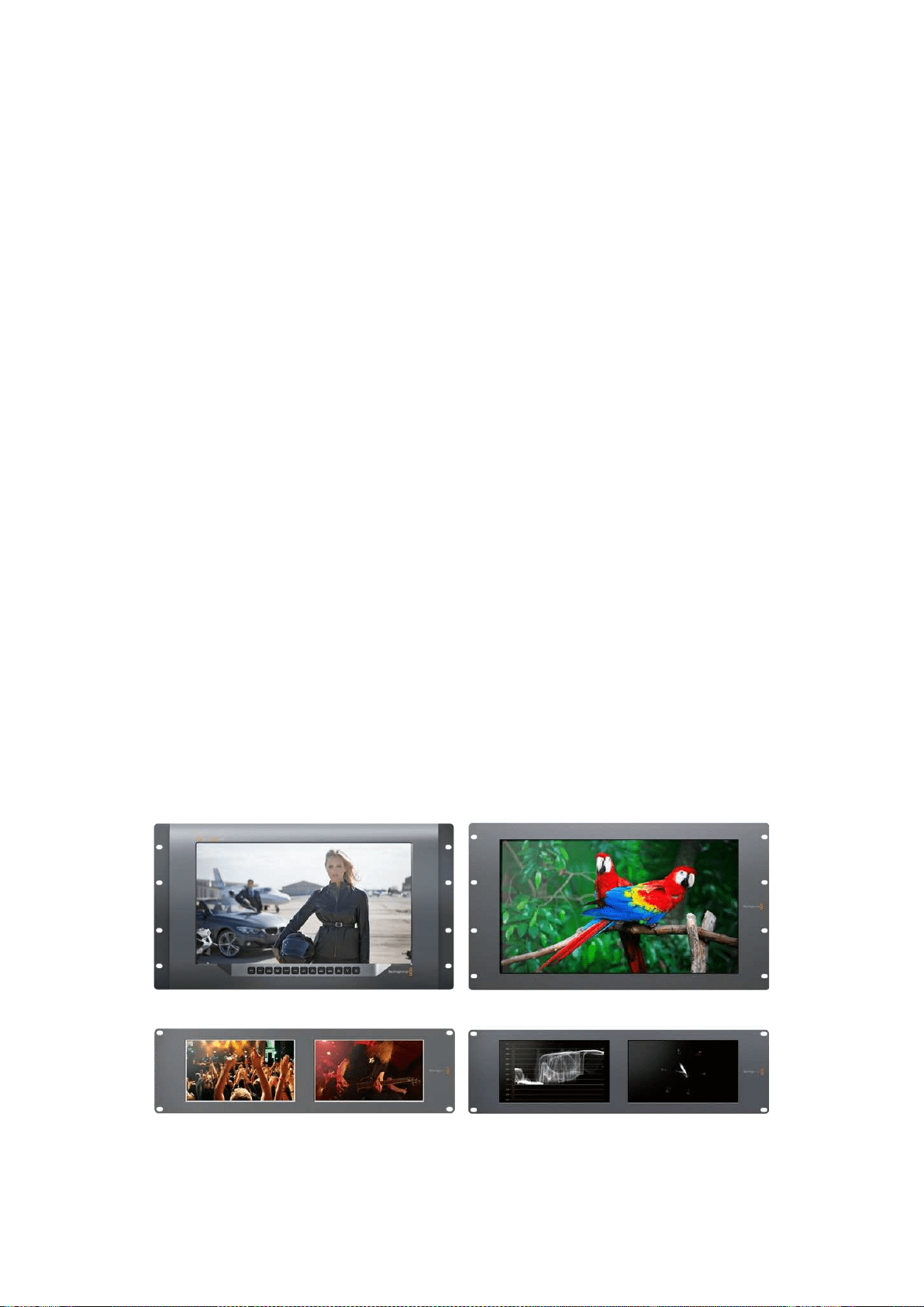
309Operazioni preliminari
Operazioni preliminari
SmartView e SmartScope
I monitor SmartView sono perfetti per il monitoraggio su rack. Periniziare basta collegare il
cavo di alimentazione e connettere la fonte video SDI. La gamma SmartView e SmartScope
consiste di quattro modelli.
SmartView 4K ha un display LCD 4K da 15,6” che permette di monitorare video SD, HD, o
UltraHD alla risoluzione nativa di 3840x2160 pixel. I pulsanti di controllo sottostanti consentono
di selezionare facilmente gli ingressi, regolare la luminosità dello schermo, individuare il rumore
nel canale del blu, visualizzare le informazioni nei bordi dell’immagine, applicare le LUT 3D e
altro ancora.
SmartView HD ha un display LCD HD da 17” perfetto per il monitoraggio a piena risoluzione HD.
SmartView Duo è dotato di due monitor per visualizzare contemporaneamente segnali video
diversi. Ad esempio mentre uno mostra un segnale YUV 4:2:2, l’altro mostra un segnale RGB
4:4:4; uno il formato NTSC e l’altro il PAL. Sono possibili numerose combinazioni, e basta
connettere un singolo cavo SDI ad ogni monitor per visualizzarle.
SmartScope Duo 4K ha tutte le caratteristiche di SmartView Duo e in più visualizza anche la
forma d’onda, il vetteroscopio, e altri visualizzatori di segnale comunemente usati per
monitorare i livelli audio e video in tempo reale. Inoltre è perfettamente compatibile con il
formato Ultra HD 4K.
Tutti gli ingressi dei monitor SmartView e SmartScope rilevano automaticamente i formati SD,
HD o 3G-SDI, incluso il 2K. SmartView 4K rileva anche l’Ultra HD 2160p60 tramite 12G-SDI.
SmartScope Duo 4K rileva automaticamante l’Ultra HD 4K tramite 6G-SDI.
Per modificare le impostazioni di più SmartView e SmartScope in modalità remota da un unico
computer, connettili tra di loro tramite ethernet. In questo modo non è necessario collegare ogni
singola unità a un computer con un cavo USB ogni volta che vuoi modificarne le impostazioni.
Sei arrivato alla fine della panoramica dei modelli SmartView e SmartScope. Continua a leggere
il manuale per ulteriori informazioni su come connettere SmartView e SmartScope, configurare
le impostazioni dei monitor con Blackmagic SmartView Setup, e collegarli ad una rete.
SmartView 4K SmartView HD
SmartView Duo SmartScope Duo 4K
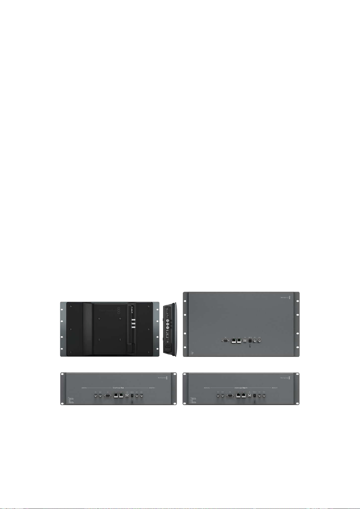
310Operazioni preliminari
Collegare le fonti video
I monitor SmartView e SmartScope hanno in dotazione connettori BNC standard per collegare
dispositivi SDI tra cui switcher, videocamere, schede di acquisizione, deck e registratori su disco.
Visualizzare le immagini
Visualizzare il video è semplicissimo: collega il dispositivo all’alimentazione e la fonte video a un
ingresso SDI. A questo punto il video dovrebbe essere immediatamente visibile. I segnali SD,
HD e 2K sono automaticamente rilevati dagli ingressi SDI e dalle uscite di loop. SmartView4K e
SmartScope Duo 4K rilevano anche l’Ultra HD 4K.
Quando l’unità non riceve alcun segnale video, la retroilluminazione si spegne, garantendo
risparmio energetico fino all’arrivo di un nuovo segnale.
Collegamento a cascata dei monitor
Ogni monitor SmartView e SmartScope ospita ingressi SDI indipendenti e uscite di loop,
per cui è possibile collegare diversi monitor a cascata di modo che visualizzino lo stesso
segnale d’ingresso:
1 Accendi l’unità 1. Connetti una fonte video a un ingresso SDI. Il video dovrebbe
apparire immediatamente.
2 Accendi l’unità 2. Connetti un cavo SDI da un’uscita di loop dell’unità 1 ad un ingresso
SDI nell’unità 2.
Non c’è limite al numero di unità che si possono interconnettere.
Se stai effettuando il monitoraggio della forma d’onda mediante SmartScope Duo 4K,
èconsigliabile connettere l’uscita del monitor 1 al monitor 2 in modo che entrambi visualizzino
lo stesso segnale d’ingresso.
Ora che il video è visibile, puoi regolare le impostazioni del monitor o selezionare i visualizzatori
su SmartScope Duo 4K con il software di configurazione di Blackmagic SmartView Setup, utile
anche per caricare LUT 3D su Blackmagic SmartView 4K.
SmartView 4K SmartView HD
SmartView Duo SmartScope Duo 4K
Collegare un computer
Per configurare le impostazioni del monitor SmartView o SmartScope, collegalo al computer
tramite USB e installa Blackmagic SmartView Setup.
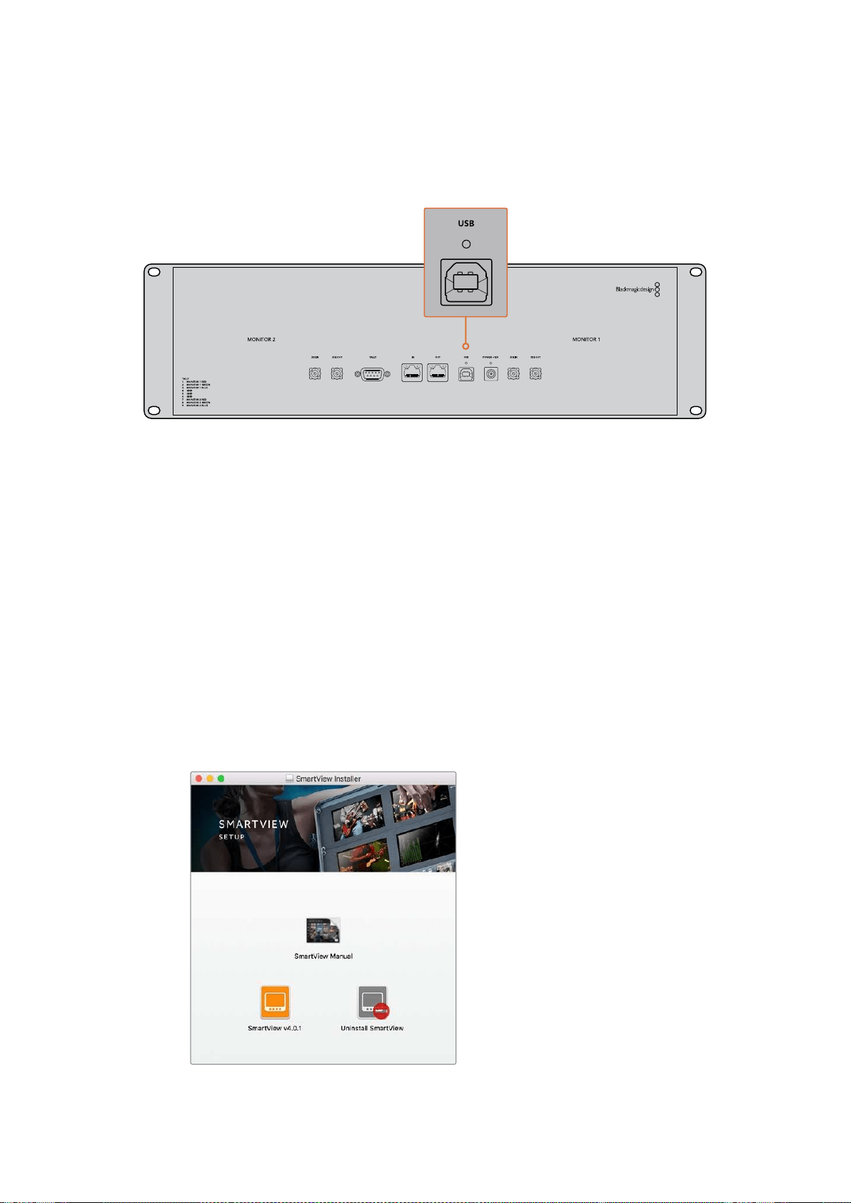
311Operazioni preliminari
La connessione USB può anche essere usata per rendere effettivi gli aggiornamenti software
scaricati dal sito di Blackmagic Design. Gli aggiornamenti danno accesso alle nuove funzionalità
e offrono il supporto per i dispositivi e i formati di prossima generazione. Il software di
configurazione Blackmagic SmartView Setup è compatibile con i computer macOS e Windows.
Installare Blackmagic SmartView Setup
Blackmagic SmartView Setup è compatibile con l’ultima versione di Sierra e High Sierra su
macOS, e con le versioni a 64 bit su Windows 8.1 e 10 con gli ultimi service pack installati.
Blackmagic SmartView Setup si può installare su più computer collegati in rete.
La scheda SD inclusa con SmartView contiene l’installer, ma suggeriamo di visitare il sito
www.blackmagicdesign.com/it/support per ottenere la versione più recente.
Installazione su macOS:
Apri la scheda SD o l’immagine disco scaricata, e fai doppio clic sull’icona di installazione
SmartView. Nella cartella delle applicazioni verrà creata una cartella SmartView che contiene il
software SmartView Setup, un programma di disinstallazione per rimuovere le versioni
precedenti quando si fa un aggiornamento, e una cartella documenti con questo manuale e
altre informazioni su SmartView.
Installazione su Windows:
Apri la scheda SD o il file zip scaricato, e fai doppio clic sull’icona di installazione SmartView.
Segui le istruzioni sullo schermo per completare l’installazione del software.
Per l’installazione su macOS, apri il file SmartView.dmg contenuto nella scheda SD,
odalla cartella dei download, e fai doppio clic sull’icona di installazione di SmartView
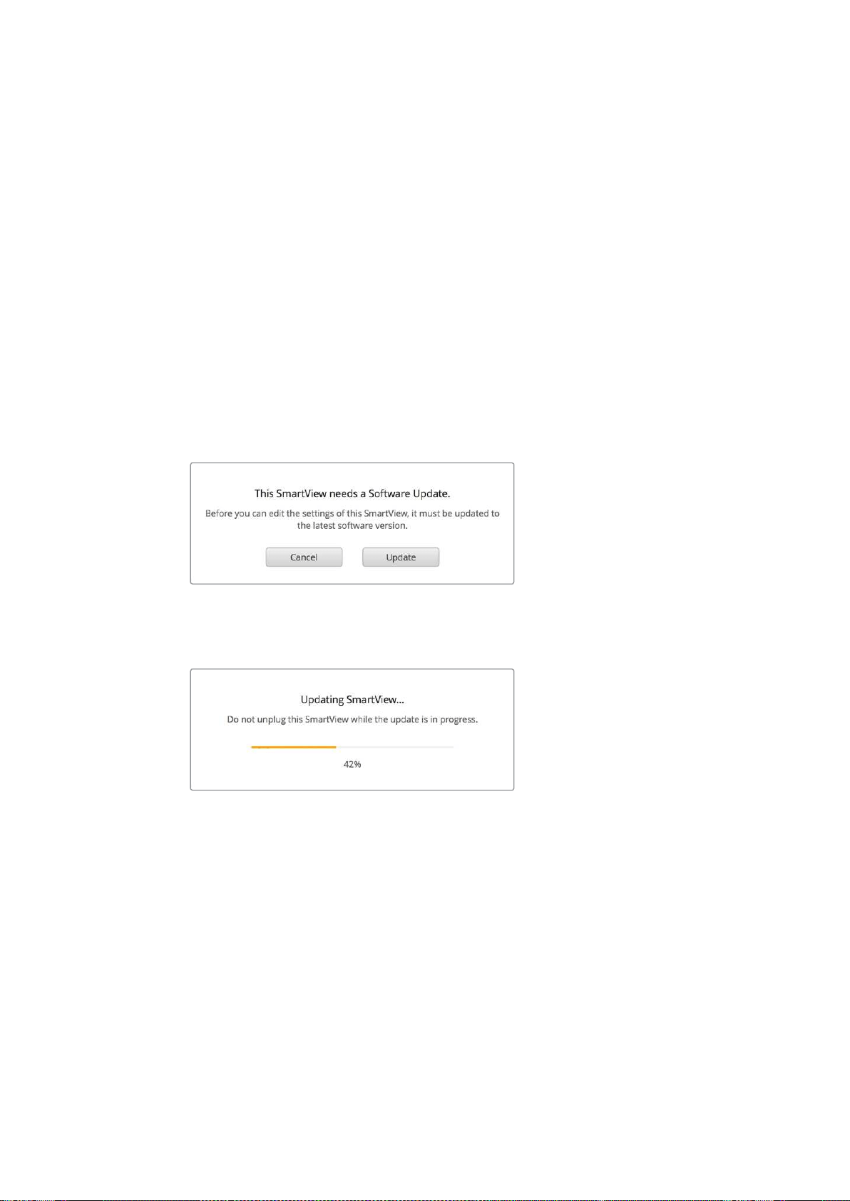
312Utilizzare Blackmagic SmartView Setup
Utilizzare Blackmagic SmartView Setup
Aggiornare il software
Dopo aver installato e avviato Blackmagic SmartView Setup, clicca sull’icona delle impostazioni
sotto il nome del tuo monitor. Potrebbe suggerirti di aggiornare il software di SmartView o
SmartScope. Per farlo:
1 Collega SmartView o SmartScope al computer tramite USB o ethernet e lancia
Blackmagic SmartView Setup.
2 Apparirà un avviso: clicca su Update. Eseguire l’aggiornamento richiede circa 5 minuti.
3 L’av v i s o This Smartview has been updated (SmartView è stato aggiornato) dovrebbe
apparire al termine dell’aggiornamento.
4 Clicca su Close.
Se il software interno è già aggiornato all’ultima versione, la pagina impostazioni di Blackmagic
SmartView Setup appare sul monitor.
Quando lanci SmartView Setup e clicchi sull’icona delle
impostazioni di SmartView o SmartScope, questo messaggio
appare se è necessario aggiornare il software interno
Eseguire l’aggiornamento richiede circa 5 minuti
Regolare le impostazioni del monitor
Una volta lanciato, Blackmagic SmartView Setup cerca immediatamente le unità SmartView o
SmartScope collegate tramite USB o ethernet e le visualizza nella home. Se hai connesso più
monitor Blackmagic alla rete, clicca sulle frecce destra e sinistra ai lati della home per
selezionare quello che vuoi impostare. Se connesso tramite USB, un’icona USB appare a fianco
al nome del monitor.
Per regolare le impostazioni, seleziona il monitor connesso via ethernet e USB e clicca
sull’icona cartella sotto il nome del monitor. La pagina delle impostazioni del monitor
selezionato si apre sullo schermo. Una volta regolati i parametri desiderati, clicca su Save per
salvarli e tornare alla home di SmartView Setup.
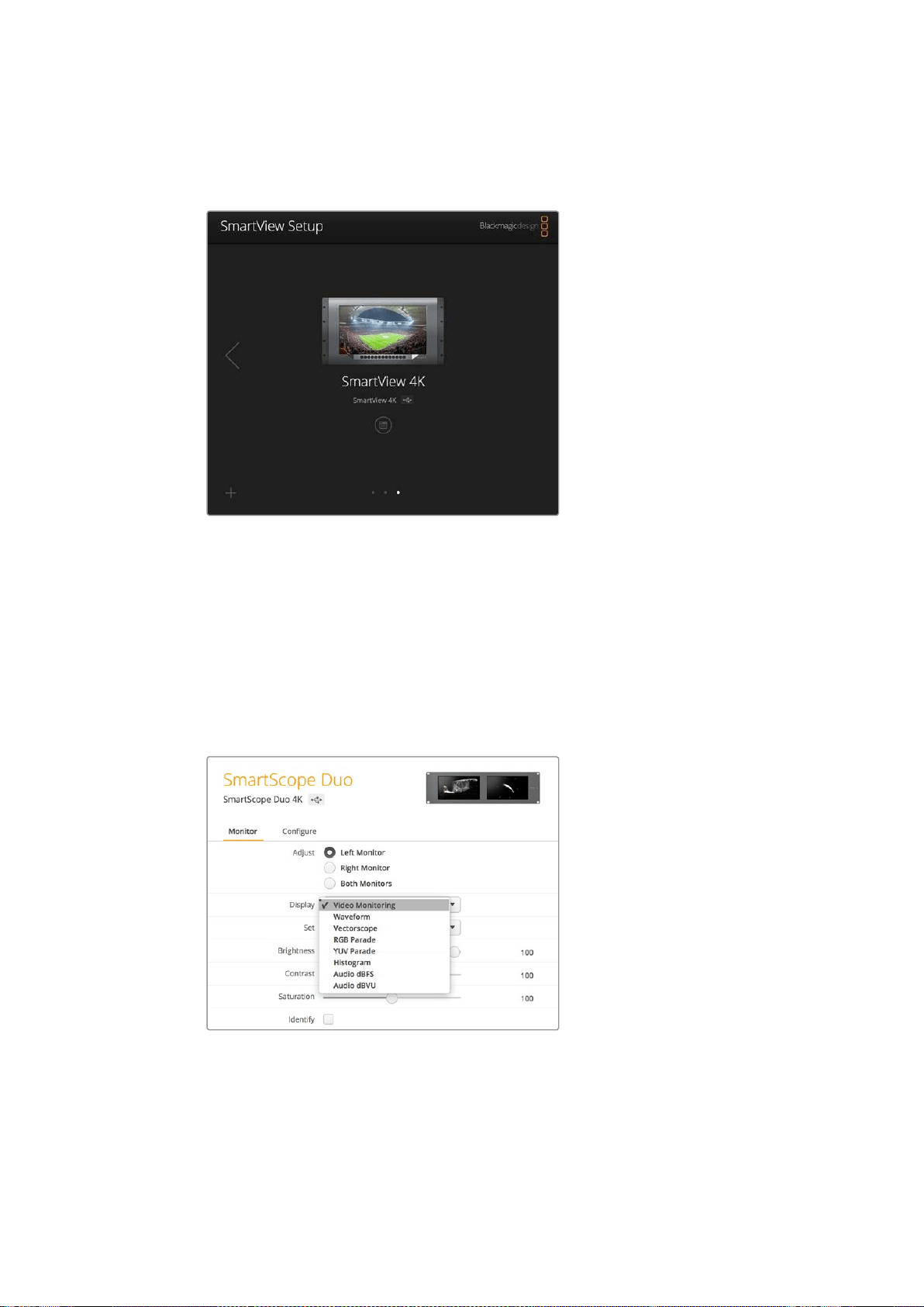
313Utilizzare Blackmagic SmartView Setup
Per informazioni sulle impostazioni disponibili per i monitor Blackmagic e su come applicarle,
consulta la sezione successiva. Per informazioni su come configurare le impostazioni di rete
utilizzando Blackmagic SmartView Setup, vai alla sezione “Regolare le impostazioni di rete”.
Blackmagic SmartView Setup cerca automaticamente le unità
SmartView e SmartScope connesse via USB o in rete. Quando aggiorni
il software interno del monitor assicurati che sia connesso tramite
USB o ethernet. Un’icona USB appare di fianco al nome del monitor
Impostazioni del monitor
Per regolare le impostazioni e i visualizzatori di ogni monitor, è necessario che siano connessi
tramite ethernet o USB. Seleziona il monitor che vuoi impostare cliccando sulle frecce sinistra e
destra della home di SmartView Setup, quindi clicca sull’icona cartella sotto il nome del monitor
interessato. La pagina delle impostazioni mostra automaticamente le opzioni relative al monitor
Blackmagic selezionato.
Quando usi uno SmartScope, la voce Display offre un menù a
discesa per scegliere i visualizzatori tecnici o il video
Adjust
Quando usi SmartScope o SmartView Duo, scegli il monitor che vuoi regolare selezionando quello
sinistro Left Monitor, quello destro Right Monitor, o entrambi Both Monitors allo stesso tempo.
Quando è selezionata l’opzione Both Monitors, qualsiasi modifica alla luminosità, al contrasto e
alla saturazione verrà applicata a entrambi i monitor su SmartView Duo e SmartScope.
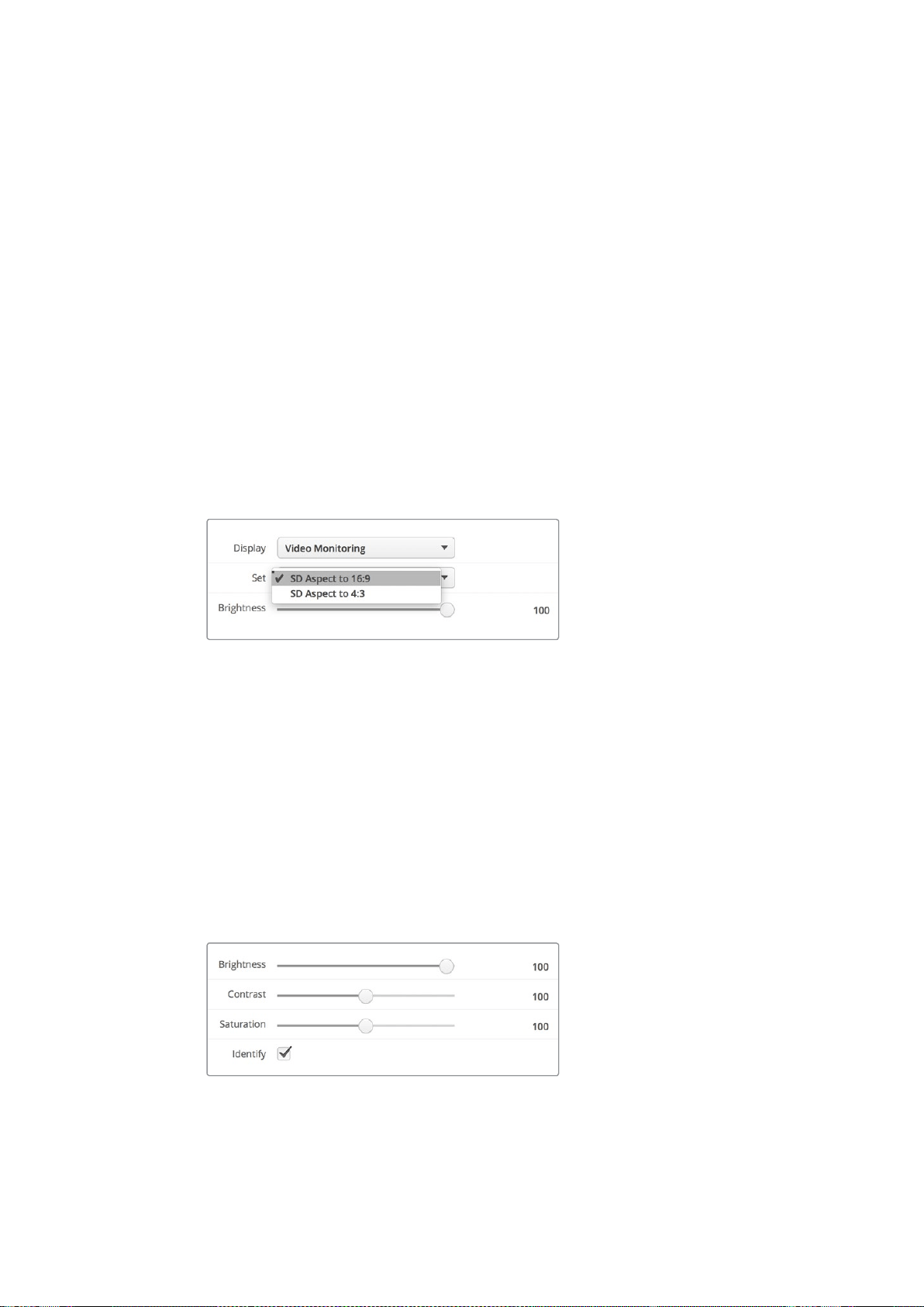
314Utilizzare Blackmagic SmartView Setup
Display
Quando usi uno SmartScope, la voce Display offre un menù a discesa per scegliere i
visualizzatori. Se vuoi vedere solamente l’immagine del video, seleziona Video Monitoring.
Set
Quando usi SmartScope, il menù a discesa alla voce Set consente di selezionare i rapporti
d’aspetto 4:3 o 16:9 per monitorare il video a definizione standard. Il menù a discesa fornisce
ulteriori opzioni di visualizzazione, tra cui vettorscopio, audio dBFS e audio dBVU.
Video Monitoring: scegli tra i rapporti d’aspetto 4:3 o 16:9 per visualizzare l’immagine
del video.
Quando visualizzi video a definizione standard con formato anamorfico widescreen,
scegli il rapporto d’aspetto 16:9. Quando visualizzi video a definizione standard con
formato tradizionale 4:3, scegli il rapporto d’aspetto 4:3.
Vectorscope: seleziona se l’input è basato su segnali di test al 100% o al 75% delle
barre colore.
Audio dBFS: seleziona la coppia di canali audio per il monitoraggio di fase.
Audio dBVU: seleziona la coppia di canali audio per il monitoraggio di fase.
Scegli SD Aspect to 16:9 con video a definizione
standard in formato anamorfico
Brightness, Contrast, Saturation
Sposta gli slider per regolare le impostazioni di luminosità Brightness, contrasto Contrast e
saturazione Saturation.
Identify
Quando la casella Identify è spuntata, ogni monitor selezionato da Blackmagic SmartView
Setup mostra un bordo bianco. Se in rete sono connesse più unità SmartView e SmartScope,
questa impostazione facilita l’identificazione visiva del monitor selezionato.
Se è utilizzata in concomitanza con l’impostazione Both Monitors, il bordo bianco appare sia su
SmartView Duo che SmartScope Duo 4K.
Sposta gli slider verso destra o sinistra per regolare luminosità,
contrasto e saturazione. Spunta la casella Identify per facilitare
l’identificazione visiva del monitor selezionato
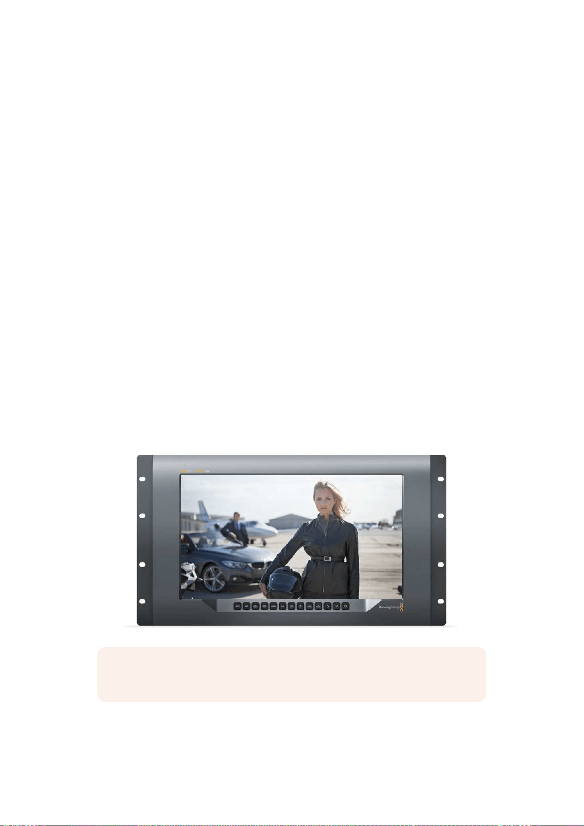
315Utilizzare SmartView 4K
Utilizzare SmartView 4K
Introduzione
SmartView 4K è un monitor broadcast Ultra HD 12G-SDI di 6 unità di rack che visualizza video
SD, HD, e Ultra HD nativo fino al 2160p60. Con un display luminoso e un ampio angolo di
visuale, offre immagini brillanti e nitidissime per il monitoraggio accurato della messa a fuoco
e del colore, supportando virtualmente qualsiasi tipo di formato video.
Progettato per lo studio e la regia mobile, SmartView 4K è incredibilmente semplice da usare.
Dotato di connettori laterali e fori di montaggio VESA, si può installare in spazi stretti, sulla
parete, o su un braccio articolato. È operabile usando i pulsanti di controllo integrato o, se non
hai accesso al pannello frontale, remotamente tramite ethernet.
Offre due ingressi 12G-SDI multirate che consentono di scegliere tra due sorgenti SDI, e un
alloggiamento per fibra ottica SFP compatibile con lo standard SMPTE, per connettere il video
tramite fibra. Trovano spazio anche un’uscita 12G-SDI per inviare il video ad altri dispositivi, e
due porte ethernet per i collegamenti di rete, il controllo remoto, e il collegamento a cascata.
Inoltre include un ingresso tally per la produzione dal vivo, e una porta USB per aggiornare il
software interno.
Grazie al software Blackmagic SmartView Setup è possibile caricare LUT 3D professionali
con estensione .cube o LUT generate in DaVinci Resolve. Una volta applicate le LUT 3D, puoi
collegare SmartView 4K direttamente alla camera e vedere le clip nella versione che più si
avvicina al look finale. Due livelli di focus peaking garantiscono riprese con una messa a fuoco
perfetta, e gli ingressi di alimentazione AC e DC ti danno l’opzione di collegare SmartView 4K
alla corrente. Oppure installa una batteria esterna per la massima mobilità sul set.
SmartView 4K è la soluzione di monitoraggio ideale per video SD, HD, e Ultra HD nella
risoluzione nativa di 3840x2160 per le produzioni broadcast in studio o in esterna.
NOTA Se connetti il monitor a una fonte di alimentazione esterna tramite l’ingresso
DC, assicurati che la fonte supporti 24 Watt a 12 Volt
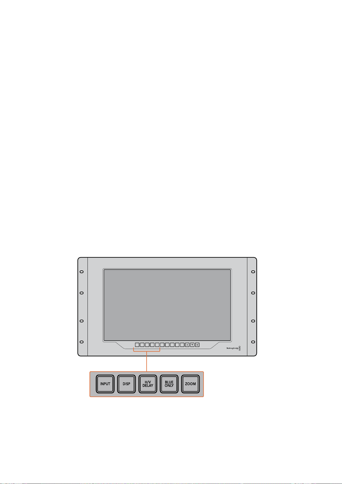
316Utilizzare SmartView 4K
Pulsanti di controllo
Una serie di pulsanti ti consentono di regolare rapidamente le impostazioni di SmartView 4K.
INPUT
Naviga tra i segnali video connessi ai due ingressi 12G-SDI e all’ingresso opzionale SFP per la
fibra ottica. Se agli ingressi non è connesso nessun segnale, SmartView 4K mostra una
schermata nera. Quando si passa da un ingresso all’altro, le informazioni sul formato di quello
connesso vengono momentaneamente visualizzate nell’angolo in alto a sinistra del monitor.
DISP
Regola la luminosità dello schermo LCD di SmartView 4K. Aumenta o diminuisci i valori
premendo i pulsanti freccia su e giù. Per chiudere questa impostazione premi di nuovo il
pulsante DISP.
H/V DELAY
Conferma la presenza di dati ausiliari integrati nel segnale video SDI. Per esempio, premi H/V
DELAY una volta per visualizzare i dati ausiliari orizzontali. Premilo di nuovo per visualizzare i
dati ausiliari verticali, utilizzati comunemente per i sottotitoli chiusi.
BLUE ONLY
Se un segnale video digitale è affetto da rumore, è molto più visibile sul canale del blu. Premi
BLU ONLY per verificare facilmente la presenza di rumore. Il monitor mostra il canale del blu
con un’immagine in bianco e nero, utile anche per controllare la messa a fuoco della camera.
ZOOM
Per ottenere una messa a fuoco precisa delle immagini della camera basta usare il pulsante
ZOOM. Premilo una volta per zoomare l’immagine, e vedere chiaramente se un oggetto è a
fuoco. Premilo di nuovo per tornare alla visualizzazione normale.
INPUT DISP
H/V
DELAY
3D
LUT 1
BLUE
ONLY
ZOOM PEAK
3D
LUT 2
H
MARK
V
MARK
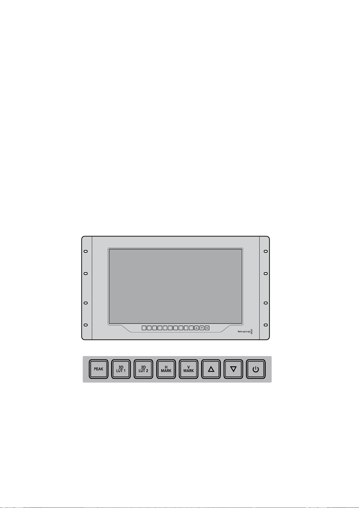
317Utilizzare SmartView 4K
PEAK
La messa a fuoco della camera si può tenere facilmente sotto controllo premendo questo
pulsante. La funzione di focus peaking mostra un contorno verde sulle alle aree più nitide
dell’immagine. Ci sono due livelli di intensità di peaking, che puoi esplorare premendo
ciclicamente il pulsante PEAK. Quando i contorni verdi raggiungono la massima intensità,
leimmagini della camera sono a fuoco.
3D LUT 1 e 3D LUT 2
Visualizza l’immagine con l’estetica delle LUT 3D personalizzate generate in DaVinci Resolve,
o delle LUT di standard dell’industria .cube. Premi il pulsante LUT una volta per attivare la LUT.
Premilo di nuovo per disattivarla. Per ulteriori informazioni su come adoperare le LUT 3D con
SmartView 4K, consulta la sezione “Caricare LUT 3D con Blackmagic SmartView Setup”.
H MARK e V MARK
Visualizza e modifica le guide di inquadratura. Le guide di inquadratura ti aiutano a comporre
leriprese o a mantenere informazioni o grafica entro la safe area dello schermo. I margini del
segnale video appaiono in misura diversa in base al modello di Tv, ecco perché è utile
visualizzare la safe area. La safe area è una sezione dello schermo che è sempre visibile a
prescindere dalla Tv o dal monitor adoperati.
Per vedere le guide di inquadratura orizzontali e verticali, premi rispettivamente i pulsanti H
MARK e V MARK. Per modificare le guide, premi nuovamente i pulsanti rispettivi. Questo ti
consente di riposizionare le guide utilizzando i pulsanti freccia su e giù. Conferma la nuova
posizione premendo ciascun pulsante. Premili di nuovo per disattivare le guide.
Frecce direzionali
Usa i pulsanti freccia su e giù per regolare i valori delle impostazioni, ad esempio la luminosità o
la posizione delle guide di inquadratura.
Accensione
Premilo una volta per accendere SmartView 4K, e premilo nuovamente per spegnerlo.
INPUT DISP
H/V
DELAY
3D
LUT 1
BLUE
ONLY
ZOOM PEAK
3D
LUT 2
H
MARK
V
MARK

318Utilizzare SmartView 4K
Caricare LUT 3D con Blackmagic SmartView Setup
SmartView 4K consente di monitorare il video attraverso delle LUT 3D. Questo ti permette di
calibrare SmartView 4K mediante apposite LUT professionali, o di visualizzare le immagini nella
versione che più si avvicina all’estetica finale. Le LUT 3D sono utili anche per sperimentare
diversi look. Per caricare le LUT su SmartView 4K basta usare Blackmagic SmartView Setup.
Inoltre poiché SmartView 4K supporta LUT professionali con estensione .cube, puoi anche
caricare LUT personalizzate generate in DaVinci Resolve di Blackmagic. Per ulteriori
informazioni su come generare file LUT, consulta il manuale di DaVinci Resolve.
Per assegnare una LUT 3D al pulsante 3D LUT 1:
1 Lancia Blackmagic SmartView Setup.
2 Premi il pulsante Load alla voce Load LUT 1. Si aprirà una finestra che ti chiederà
di indicare dove si trova il file della LUT che vuoi caricare. Seleziona il file .cube
desiderato, e conferma con il pulsante Open.
3 Per vedere la LUT che hai appena caricato, premi il pulsante 3D LUT 1 sul pannello di
SmartView 4K. Premi di nuovo lo stesso pulsante per disabilitarla.
Segui la stessa procedura per assegnare una LUT al pulsante 3D LUT 2.
Accedi a Blackmagic SmartView Setup per caricare LUT 3D su SmartView 4K

319Utilizzare SmartScope Duo 4K
Utilizzare SmartScope Duo 4K
Che cos’è Blackmagic SmartScope?
In passato i visualizzatori di segnale di qualità broadcast usati nell’industria televisiva in post
produzione erano soluzioni su misura molto costose visualizzabili singolarmente su un piccolo
schermo. Spesso hanno un design mediocre e non fanno una bella figura davanti ai clienti.
SmartScope Duo 4K include visualizzatori della forma d’onda per tenere sotto controllo ogni
aspetto del segnale video su due monitor in tempo reale. Qualsiasi modifica apportata al
segnale d’ingresso su Blackmagic SmartView Setup appare all’istante su SmartScope Duo 4K.
Oltretutto, ogni segnale di ingresso può essere inviato ad entrambi i monitor attraverso l’uscita
SDI di loop. Così facendo puoi usare il monitor destro per monitorare il segnale inviato al
monitor sinistro.
I visualizzatori disponibili su SmartScope Duo 4K sono selezionabili su Blackmagic SmartView
Setup dal menù a discesa alla voce Display.
Le sezioni seguenti approfondiscono il funzionamento di ciascun visualizzatore di segnale per
aiutarti ad interpretare le informazioni.
Accedi a Blackmagic SmartView Setup per scegliere i visualizzatori che
vuoi monitorare sui due display di SmartScope Duo 4K
Monitoraggio video
La modalità Video Monitoring ti consente di visualizzare il video ricevuto da SmartScope.
Se il segnale d’ingresso è SD, nel menù a discesa alla voce Set puoi scegliere tra le opzioni
pillarbox 4:3 o 16:9. Il video riflette all’istante qualsiasi modifica apportata alle impostazioni di
luminosità, contrasto e saturazione dello schermo LCD. Queste impostazioni interessano solo il
monitor, non il segnale video, pertanto i visualizzatori non rispondono ad eventuali modifiche.
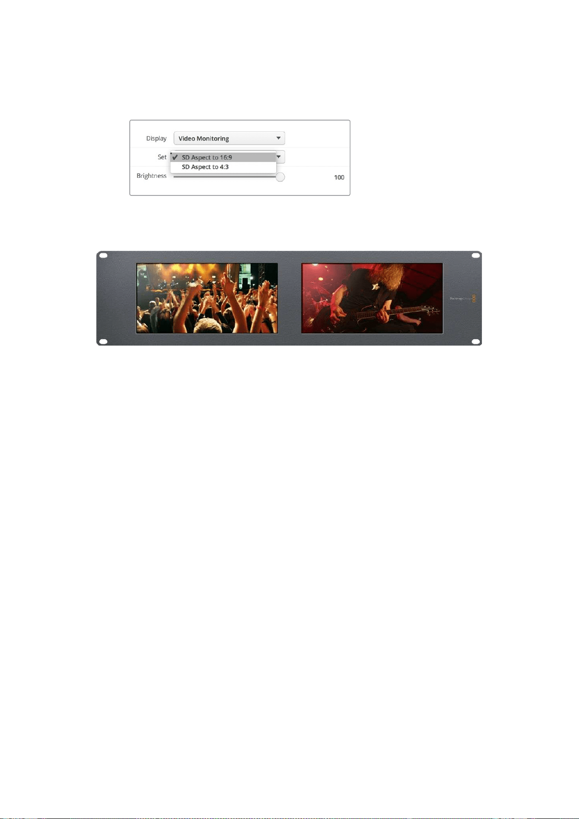
320Utilizzare SmartScope Duo 4K
Spesso è utile visualizzare il video su un monitor e monitorare i segnali sull’altro. Per farlo,
connetti l’uscita di loop SDI di “Monitor 1” all’ingresso SDI di “Monitor 2”.
Accedi a Blackmagic SmartView Setup per selezionare tra pillarbox
4:3 e anamorfico 16:9 per il video SD. Scegli SD Aspect to 16:9
per il video a definizione standard in formato anamorfico
Scegli l’impostazione Video Monitoring per visualizzare le immagini come sullo schermo di una Tv
Forma d’onda
Questo visualizzatore mostra una forma d’onda con codifica digitale simile a quella della
luminanza tradizionale, che serve per monitorare e regolare i livelli di luma (luminosità) del
segnale video.
I tradizionali visualizzatori della forma d’onda della luminanza sono compatibili solo con video
analogico composito a definizione standard. SmartScope Duo 4K invece ammette Ultra HD, HD,
e SD, per cui regolare i livelli di luminanza, anche in fase di monitoraggio di formati video digitali
ad alta definizione, è facile e costante.
Su Blackmagic SmartView Setup, seleziona Waveform dal menù a discesa alla voce Display.
Quando monitori la forma d’onda, assicurarti che i neri non scendano al di sotto dello 0% e
ibianchi non superino il 100% per mantenere i livelli entro la norma.
La forma d'onda è una rappresentazione grafica dell'immagine che mostra i valori di luminanza
nella stessa posizione del relativo fotogramma. Per esempio, se una parte del cielo
èsovraesposta, il problema è visibile nella stessa posizione orizzontale sulla forma d’onda,
proprio come nel fotogramma.
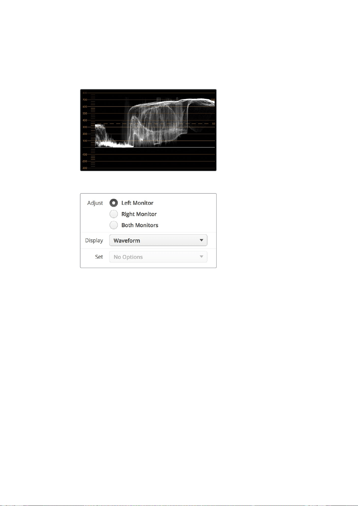
321Utilizzare SmartScope Duo 4K
La forma d'onda varia in base alle immagini. Per esempio se stai monitorando video ad alto
contrasto, i valori del grigio medio potrebbero non essere visibili. L’esempio qui sotto mostra la
forma d’onda di un’immagine esposta uniformemente, con un’area scura a sinistra e aree più
luminose nella zona centrale e destra del fotogramma.
La forma d'onda mostra i valori di luminanza
Seleziona Display > Waveform su Blackmagic SmartView Setup
per monitorare la luminanza del segnale video
Vettorscopio
Il vettorscopio mostra i colori di un segnale video. A seconda degli standard delle barre colore
dei segnali di test utilizzati dal tuo studio, seleziona 100% o 75% dal menù a discesa alla voce
Set su Blackmagic SmartView Setup.
Nota che il vettorscopio non consente di controllare i livelli fuori norma. Per questo tipo di
monitoraggio bisogna ricorrere all’allineamento RGB. La ragione per cui il vettorscopio non è
adatto a controllare tali livelli è che per farlo sono necessari sia i valori di luminanza che di
crominanza. Ad esempio, i colori vicino al bianco o al nero nel video non possono essere
saturati come i colori molto più forti, utilizzabili nei grigi medi. Poiché il vettorscopio mostra solo
i colori e non i valori di luminanza, non può essere adoperato unicamente per controllare i colori
fuori norma.
Il vettorscopio è lo strumento migliore per controllare i livelli di colore delle vecchie
videocassette analogiche dove è necessario regolare la crominanza. Basta riprodurre il
segmento delle barre colore della videocassetta e regolare le impostazioni di crominanza e
tonalità per configurare i colori del video all’interno dei riquadri nel reticolo.
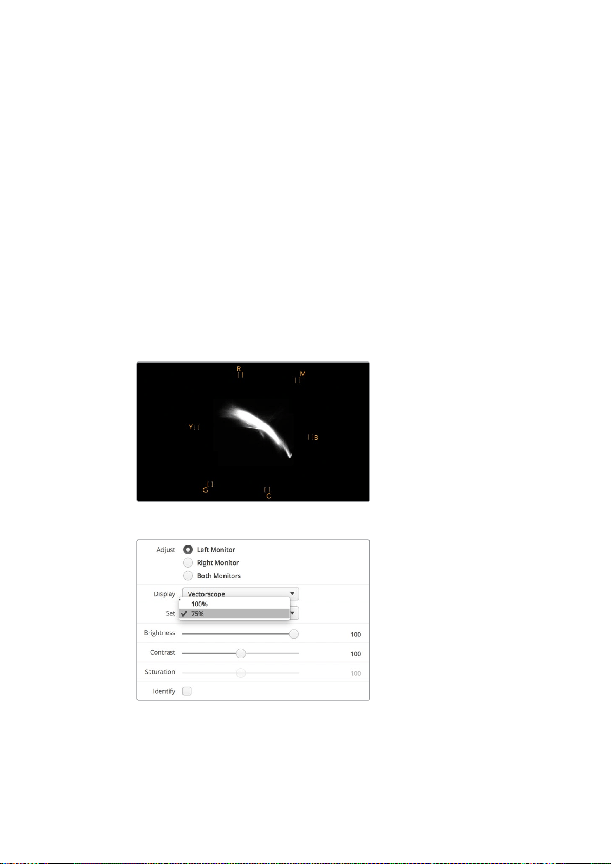
322Utilizzare SmartScope Duo 4K
Il vettorscopio è anche perfetto in fase di correzione colore per verificare che il bilanciamento
del bianco sia corretto, o la presenza di una tinta di colore. Se il video ha una tinta colorata, la
forma slitta dal centro del grafico e potrebbero apparire due punti centrali. Normalmente il
blanking del segnale video crea un punto nel centro del vettorscopio perché il blanking del
video è video nero senza alcun colore. Il blanking fornisce un punto di riferimento utile per
riconoscere aree di video nero senza alcuna informazione sul colore.
Se il video ha una tinta colorata, i neri si spostano dal colore e dal centro. Il grado di
spostamento rappresenta la quantità di tinta di colore presente nel video, ed è visibile nei
dettagli bianchi e neri. Ecco perché il vettorscopio è uno strumento prezioso per rimuovere
la tinta colorata e riacquistare il corretto bilanciamento del bianco.
Il vettorscopio ti consente di spingere i colori del video al limite, senza inavvertitamente
compromettere i bianchi e i neri. Il bilanciamento del bianco si può monitorare sull’allineamento
RGB e sul vettorscopio, ma quest'ultimo è particolarmente indicato per controllare il
bilanciamento del colore.
Quando esegui la correzione colore dell’incarnato, soprattutto dei visi, è consigliabile
mantenere la saturazione dei colori caldi sulla linea diagonale che va circa dal centro alle
ore 10 sul vettorscopio. Questa linea è conosciuta come "fleshtone line" e si basa sul colore
del sangue sottopelle. È utile per tutti i tipi di pigmentazione della pelle, ed è il miglior modo
per ottenere tonalità realistiche e naturali.
Il vettorscopio mostra la “fleshtone line” in direzione ore 10
Imposta il vettorscopio su 100% o 75% per
i segnali di test delle barre colore
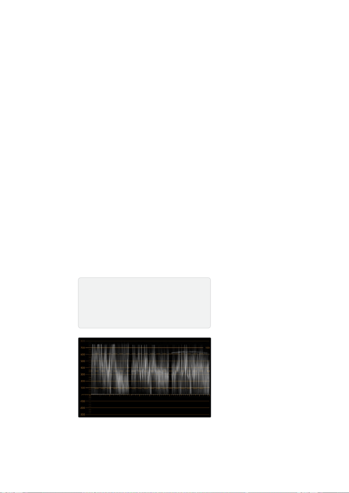
323Utilizzare SmartScope Duo 4K
Allineamento RGB e YUV
Gli allineamenti RGB e YUV sono ideali per controllare i livelli e mantenerli entro la norma.
Quando esegui la correzione colore, seleziona l’allineamento RGB RGB Parade dal menù a
discesa alla voce Display su Blackmagic SmartView Setup. Questo visualizzatore mostra
l’altezza totale dei canali del colore rosso, verde e blu. Monitorare i livelli di ogni canale di
colore facilita la correzione colore e indica il bilanciamento del colore nei neri, nei mezzitoni e
nei bianchi del segnale video. L’allineamento RGB ti consente di identificare i dettagli comuni
nei canali del rosso, del verde e del blu, agevolando il bilanciamento del colore e la rimozione
di tinte indesiderate.
Quando esegui la correzione colore, assicurati che i livelli video siano completi ma privi di
clipping. Se vuoi aumentare i livelli del video, assicurati che non superino il limite RGB superiore
per non andare fuori norma. Anche se alcuni dispositivi non generano livelli RGB 100% fuori
norma, altri lo fanno. SmartScope Duo 4K permette di individuare i livelli fuori norma ogni volta
che compaiono.
Il superamento della soglia consentita dalla norma potrebbe verificarsi anche con i livelli di
bianco e di nero. In alcuni sistemi di correzione colore, i livelli di nero si possono abbassare al di
sotto del punto nero dello 0%. Se i livelli di nero superano la soglia consentita, basta aumentare
il lift o il gain per eliminarli, ma controlla il reticolo 100% per assicurarti che il segnale video non
abbia generato colori fuori norma nei bianchi.
Per controllare i livelli YUV, seleziona YUV Parade dal menù a discesa alla voce Display. Questo
visualizzatore separa i valori di luminanza da quelli di crominanza, ovvero il formato dei segnali
video delle trasmissioni televisive. La rappresentazione grafica più a sinistra mostra le informazioni
di luminanza mentre la seconda e la terza le informazioni di crominanza. L’allineamento YUV è utile
per calibrare i valori di crominanza del segnale video secondo le barre colore di test, in modo che
i colori siano rappresentati accuratamente e il segnale trasmesso visualizzabile su qualsiasi Tv.
La correzione colore è un processo costante di regolazione, volto ad ottenere le migliori
immagini senza generare livelli fuori norma.
Allineamento RGB
Terminologia correzione colore
Blacks – Livelli dei neri nel segnale video
Mids – Livelli del grigio medio nel segnale video
Whites – Livelli dei bianchi nel segnale video

324Utilizzare SmartScope Duo 4K
Allineamento YUV
Seleziona RGB Parade o YUV Parade dal menù a discesa
alla voce Display su Blackmagic SmartView Setup
Istogramma
L’istogramma è uno dei visualizzatori di segnale più usato dai grafici e dagli operatori di ripresa.
Mostra la distribuzione delle informazioni dei bianchi e dei neri, aiutando a individuare i livelli a
rischio di clipping, e gli effetti risultanti dai cambiamenti di gamma sulle immagini.
I neri del video sono visualizzati a sinistra del grafico, e i bianchi a destra. Solitamente ogni
video dovrebbe trovarsi tra gli intervalli 0% e 100% dell’istogramma. Se il video va al di sotto
dello 0% o al di sopra del 100%, è affetto da clipping. Eliminando le informazioni dei bianchi e
dei neri, il clipping tende a limitare la flessibilità creativa della correzione colore in fase di post
produzione. Quando giri, mantieni il video sopra la clip nera e sotto la clip bianca in modo da
poter successivamente avere maggiore libertà di regolare i colori senza che i bianchi e i neri
appaiano piatti o incompleti nei dettagli.
Se durante la correzione colore decidi di limitare volontariamente il segnale video, l’istogramma
mostra gli effetti e la quantità di clipping. Per un risultato simile, ma con meno clipping e
mantenendo maggiori dettagli, puoi regolare la gamma.
L’istogramma non è adatto a controllare i livelli fuori norma, ma consente di farlo per i bianchi e i
neri. Questo strumento non mostra i colori, per cui anche se all’apparenza visualizza livelli nella
norma, è possibile che il video contenga colori fuori norma. L’allineamento RGB è lo strumento
migliore per monitorare i livelli fuori norma poiché li visualizza negli elementi sia del colore che
della luminanza del segnale video.

325Utilizzare SmartScope Duo 4K
L’istogramma mostra la distribuzione dei bianchi e dei neri
Seleziona Histogram dal menù a discesa alla voce
Display su Blackmagic SmartView Setup
Monitoraggio audio
L’indicatore audio mostra i livelli dell’audio integrato nel segnale video SDI. Isola fino a 16 canali
di audio integrato e li visualizza nel formato dBVU o dBFS.
L’indicatore VU mostra i livelli medi del segnale, è semplice da usare e molto comune nei
dispositivi datati. Il VU è calibrato secondo la raccomandazione SMPTE di un segnale di test di
tono di 1 kHz impostato su -20 dBFS.
Il dBFS è essenzialmente un indicatore del segnale audio digitale complessivo ed è comune nei
moderni dispositivi digitali.
L’indicatore destro mostra coppie di canali audio, selezionabili dal menù a discesa alla voce Set,
per esempio canale 1 e 2, 3 e 4, e così via. L’indicatore posiziona l’audio sugli assi X e Y e indica
problemi di bilanciamento, condizioni di fuori fase, e se una traccia audio è mono o stereo.
L’audio mono dovrebbe apparire come una singola linea verticale “in fase”. Se la linea è
orizzontale, l’audio è “fuori fase” e potrebbe scomparire (perdita di audio) quando viene
ricevuto dai dispositivi a valle. La fase acustica è una delle falle più comuni nelle grandi
strutture dove è probabile che i cavi non siano connessi correttamente.
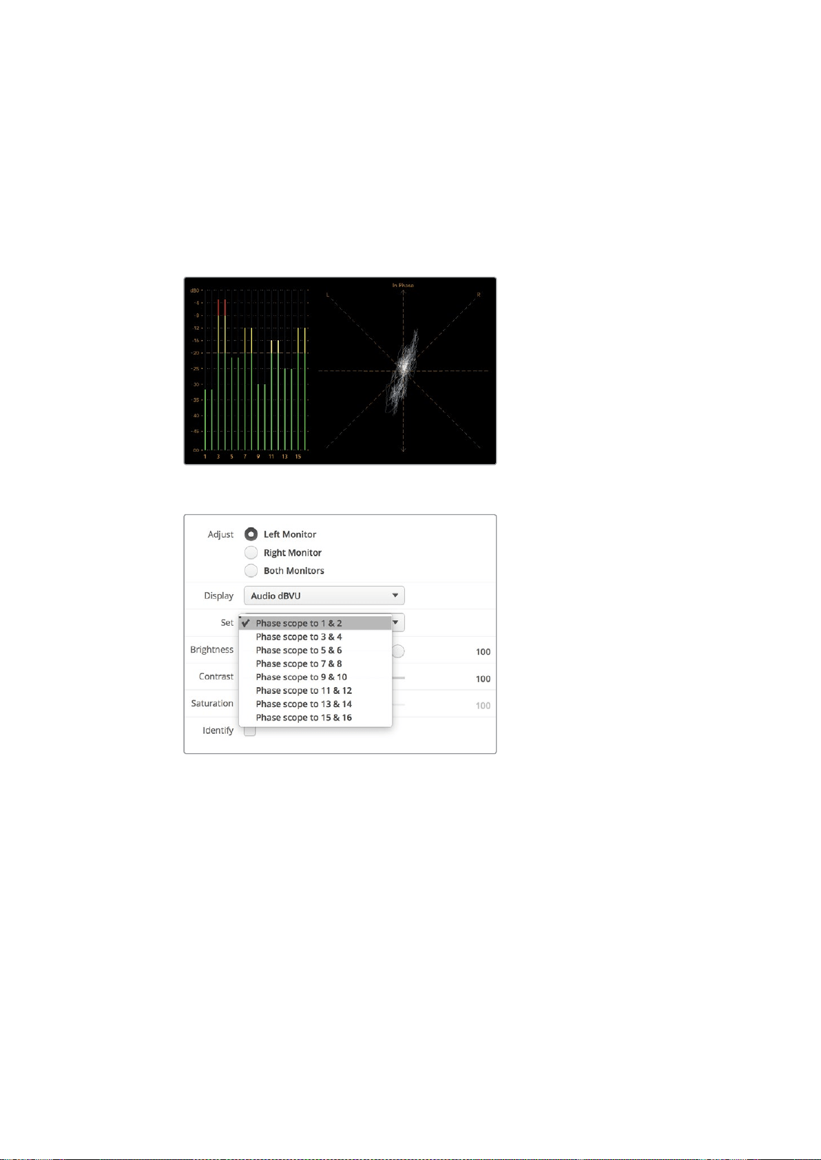
326Collegarsi ad una rete
Quando monitori i segnali stereo, la linea dell’indicatore di destra si affievolisce, a
rappresentare la differenza tra i canali audio destro e sinistro. Maggiore è la quantità di suono
stereo nella traccia audio e più circolare è la linea che appare. Se l’audio contiene una quantità
minima di suono stereo, la forma del segnale appare concentrata intorno all’asse verticale.
I dialoghi tendono ad apparire come una linea verticale, mentre la musica ad alto contenuto
stereofonico fa gonfiare la forma del segnale. Questo succede perché l’audio mono è L+R ed
appare sull’asse verticale, mentre il contenuto stereo è L-R ed appare sull’asse orizzontale per
indicarne la differenza.
L’indicatore audio mostra il livello dei picchi e il bilanciamento audio
Seleziona la coppia di canali audio che vuoi
monitorare dal menù a discesa alla voce Set
Collegarsi ad una rete
Collegando un monitor SmartView o SmartScope ad una rete, puoi regolare le impostazioni di
più unità remotamente.
Anche se i monitor SmartView e SmartScope visualizzano il video senza bisogno di
configurazione, tutte le impostazioni di rete vanno impostate prima dell’utilizzo. Per configurare
le impostazioni di rete è necessario collegare il dispositivo a un computer tramite USB.
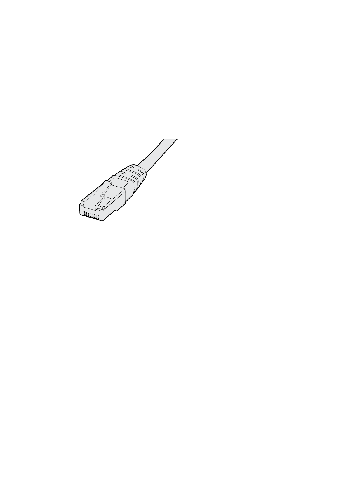
327Collegarsi ad una rete
Connessione ethernet diretta
La configurazione remota del monitor può essere fatta mediante una connessione ethernet
diretta al tuo computer. Non è necessario un interruttore di rete, velocizzando i tempi di
installazione e impostazione. Unità aggiuntive possono essere collegate a cascata grazie alla
porta ethernet di loop su ogni unità. Tutte le unità connesse devono essere collegate
all’alimentazione.
Se vuoi connettere diverse unità senza usare gli indirizzi IP della rete del tuo studio, o se non
hai già una rete, basta collegarle direttamente alla porta ethernet del tuo computer. Questo è
un modo rapido per collegare anche SmartView e SmartScope tramite ethernet poiché non c’è
bisogno di collegare cavi a interruttori di rete.
Connettore ethernet
Connessione ethernet con interruttore di rete
Se vuoi connettere più unità alla stessa rete, basta collegare solo uno SmartView o SmartScope
all’interruttore di rete e collegare a cascata il resto dei monitor utilizzando la porta ethernet di
loop di ciascuno. In questo modo è sufficiente una singola porta dell’interruttore, per un
cablaggio semplice e ordinato. Tutte le unità devono essere collegate all’alimentazione.
Collegarsi ad un interruttore di rete consente di cambiare le impostazioni delle unità da
qualsiasi computer in rete. I computer Mac o Windows permettono di farlo anche attraverso una
connessione WiFi se la tua rete ha un punto d’accesso.
Per connettere SmartView o SmartScope ad una rete locale tramite IP, segui queste istruzioni:
1 Collega l’unità all’alimentazione.
2 Collega l’unità a un interruttore di rete, o direttamente al tuo computer, con un cavo
ethernet RJ45 standard.
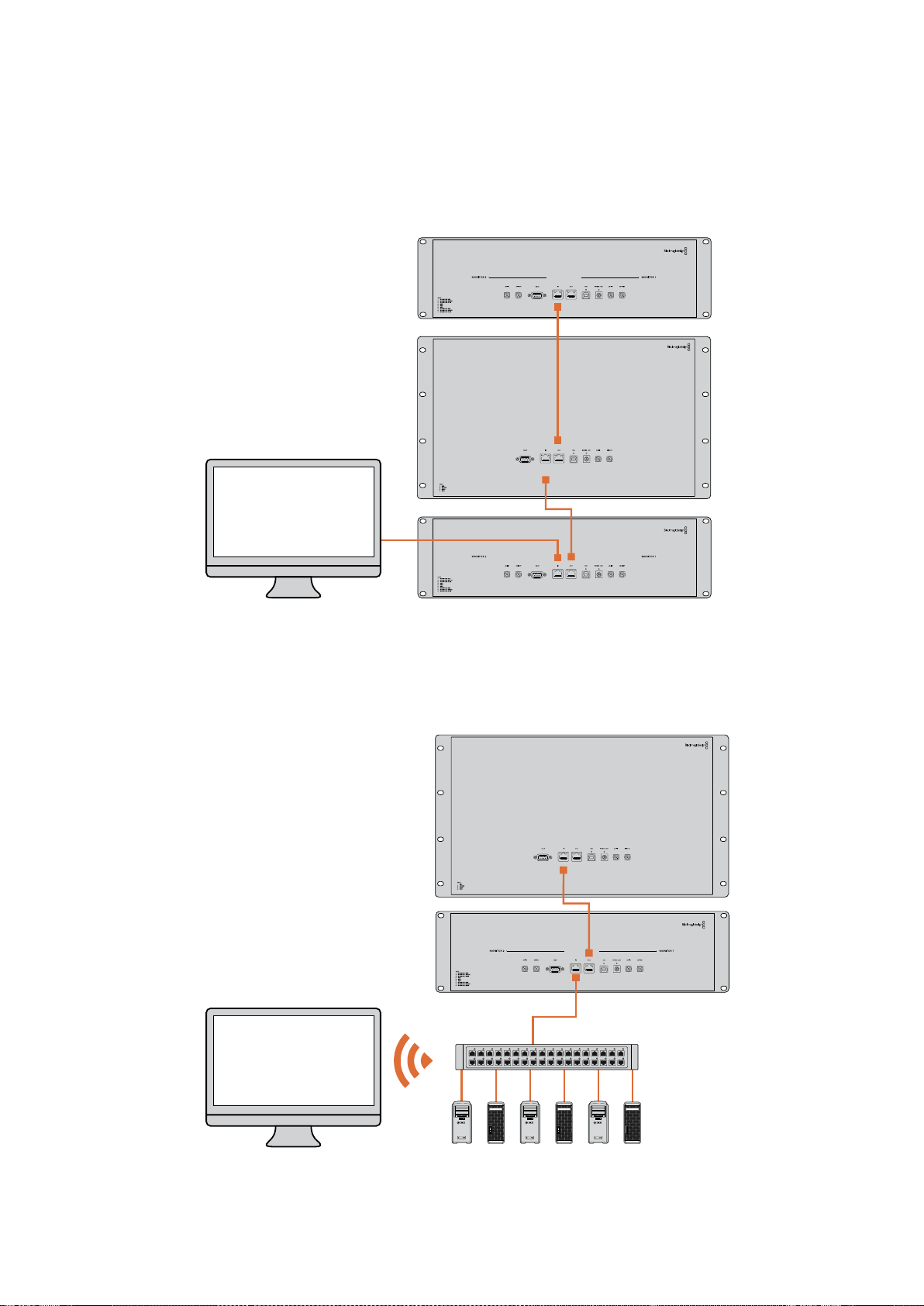
328Collegarsi ad una rete
Diagramma di connessione ethernet diretta
Collega direttamente la porta ethernet di un computer all’unità, invece di ricorrere a un
interruttore di rete. Unità aggiuntive si possono collegare a cascata, evitando di inserire
numerosi cavi nell’interruttore di rete. Tutte le unità devono essere collegate all’alimentazione.
Diagramma di connessione ethernet con interruttore di rete
Se vuoi connettere diverse unità alla rete del tuo studio, basta collegarne una sola
all’interruttore di rete. Le altre si possono collegare a cascata per cui non è necessario inserire
numerosi cavi nell’interruttore di rete. Tutte le unità devono essere collegate all’alimentazione.
SmartScope 4KDuo
SmartScope 4KDuo
Interruttore di rete
Ethernet
Computer client

329Regolare le impostazioni di rete
Regolare le impostazioni di rete
Impostazioni di rete
Nome dispositivo
È consigliabile cambiare il nome del dispositivo in modo che ogni unità SmartView o
SmartScope sia facile da identificare in una rete, per esempio. “Camera 1 e 2”, “Uscita
multiview”, “Feed 4K” e così via.
Per cambiare il nome del dispositivo, assicurati che sia connesso tramite ethernet o USB. Lancia
Blackmagic SmartView Setup e clicca sull’icona delle impostazioni sotto il nome del monitor
desiderato. Nella pagina delle impostazioni, clicca su Network e cambia il nome del monitor
nella sezione Details. Se il software rileva un nome invalido, un’icona di avvertenza appare
vicino al nome. Se il nome è valido, appare una spunta verde. Premi Invio sulla tastiera per
confermare il nuovo nome.
Impostazioni di rete
Per cambiare le impostazioni di rete su Blackmagic SmartView Setup, il monitor deve essere
collegato al computer tramite USB, non via ethernet.
SmartView e SmartScope usano di default DHCP per ottenere automaticamente un indirizzo
IPdalla tua rete.
In assenza di un server DHCP, puoi abilitare la funzione “internet sharing” su macOS, o
“internetconnection sharing” (ICS) su Windows 8.1 o Windows 10, per fornire gli indirizzi DHCP
ad ogni unità connessa. In questo modo si evita di dover assegnare manualmente indirizzi IP
statici ad ogni unità. Puoi usare questa funzione per fornire indirizzi DHCP anche se il tuo
computer non ha una connessione internet. Consulta la sezione “Help” della documentazione
di macOS e Windows 8.1 e 10 per informazioni dettagliate su internet sharing.
Se la tua configurazione non ammette DHCP, usa un indirizzo IP statico. Richiedi un indirizzo
IPaggiuntivo al tuo amministratore di sistema per evitare un conflitto di IP nella rete. Per ogni
unità SmartView e SmartScope sarà necessario specificare un indirizzo IP unico e una
maschera di sottorete condivisa. Non è necessario cambiare i valori di default del gateway a
meno che non si intenda connettere le unità ad una rete gateway, ad esempio un
router internet.
Se la rete non rileva nessun monitor SmartView o SmartScope, è probabile che le unità non
abbiano ricevuto gli indirizzi IP tramite DHCP ed è necessario configurare manualmente ogni
unità con le impostazioni di rete appropriate.
1 Collega il monitor SmartView o SmartScope al computer tramite USB e lancia
Blackmagic SmartView Setup.
2 Il monitor appare automaticamente nella home di Blackmagic SmartView Setup,
affiancato da un’icona USB.
3 Regola le impostazioni di rete del monitor.
4 Ripeti lo stesso procedimento per tutte le unità che non hanno ricevuto un indirizzo IP
tramite DHCP.
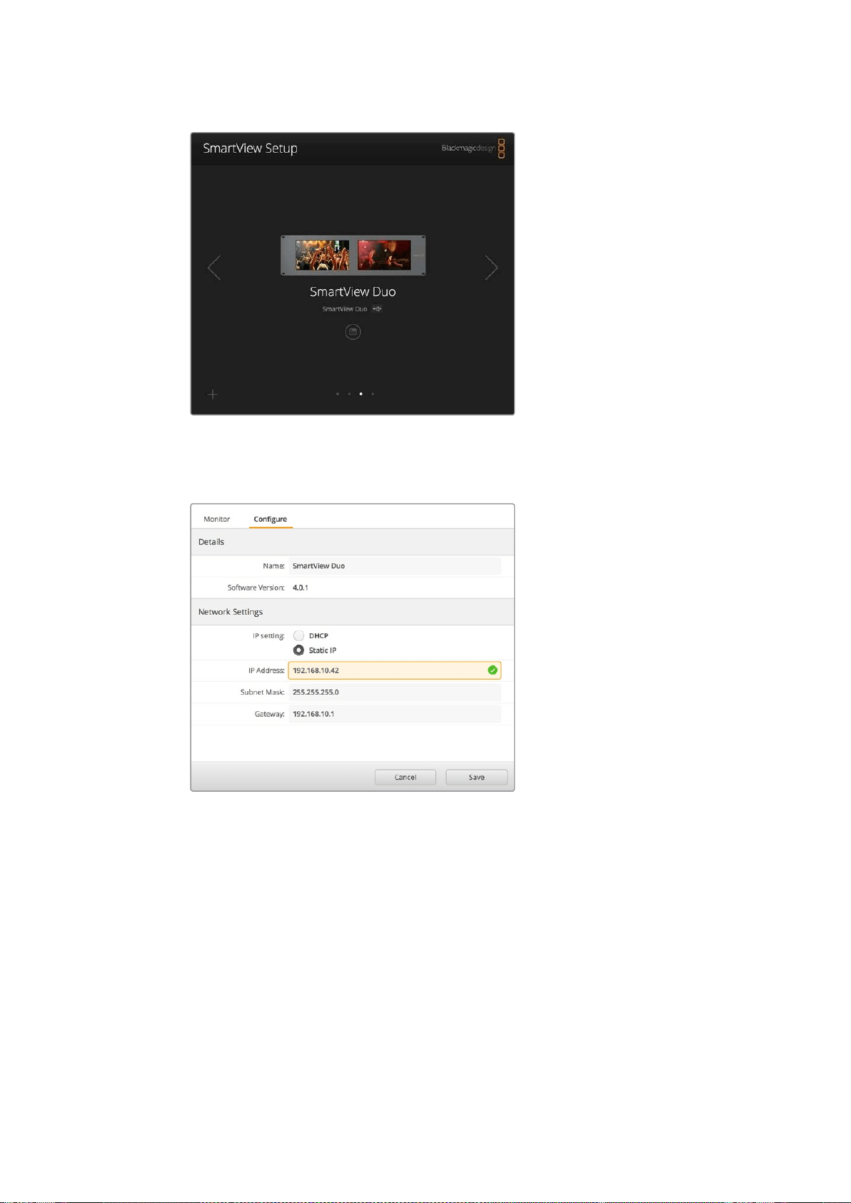
330Regolare le impostazioni di rete
L’icona USB vicino al nome del monitor indica che l’unità è
collegata al computer tramite USB. Per regolare le impostazioni
di rete del monitor, è necessario connetterlo tramite USB
Le impostazioni di rete consentono di scegliere tra DHCP e un
indirizzo IP statico e si possono cambiare solo tramite USB
Aggiungere manualmente un monitor Blackmagic alla rete
Se SmartView o SmartScope Duo 4K hanno già un indirizzo IP, ma non appare automaticamente
nella home di Blackmagic SmartView Setup, aggiungi manualmente il monitor alla rete. Per farlo:
1 Assicurati che il monitor sia connesso tramite ethernet. Clicca sull’icona + in basso a
sinistra per aprire la finestra Add a Blackmagic monitor.
2 Digita l’indirizzo IP del monitor e clicca su Add.
3 Il software ne verificherà la presenza e lo aggiungerà alla lista dei monitor connessi
nella home di SmartView Setup. Clicca sulla freccia destra per vedere il monitor
appena aggiunto.

331Utilizzare la funzione tally
Aggiungi manualmente un monitor SmartView
o SmartScope alla lista dei monitor connessi
cliccando sull’icona + e inserendo l’indirizzo IP
Utilizzare la funzione tally
Connettori pin della porta tally
SmartView e SmartScope dispongono di una porta tally. Se non intendi usare questa funzione,
passa direttamente alla prossima sezione.
Lo schermo di SmartView e SmartScope mostra bordi tally indipendenti in rosso, verde o blu,
a indicare il segnale in onda, l’anteprima, o la registrazione.
È possibile cablare i contatti della porta tally D-sub a 9 pin direttamente da switcher e sistemi di
automazione. Per informazioni su come cablare la porta tally per l’utilizzo con switcher o sistemi
di automazione, consulta la tabella qui sotto.
Sul retro dell’unità trovi la descrizione dei pin della porta D per visualizzare bordi tally rosso,
verde e blu sui singoli monitor.
Bordi tally verde e rosso sui monitor SmartView Duo
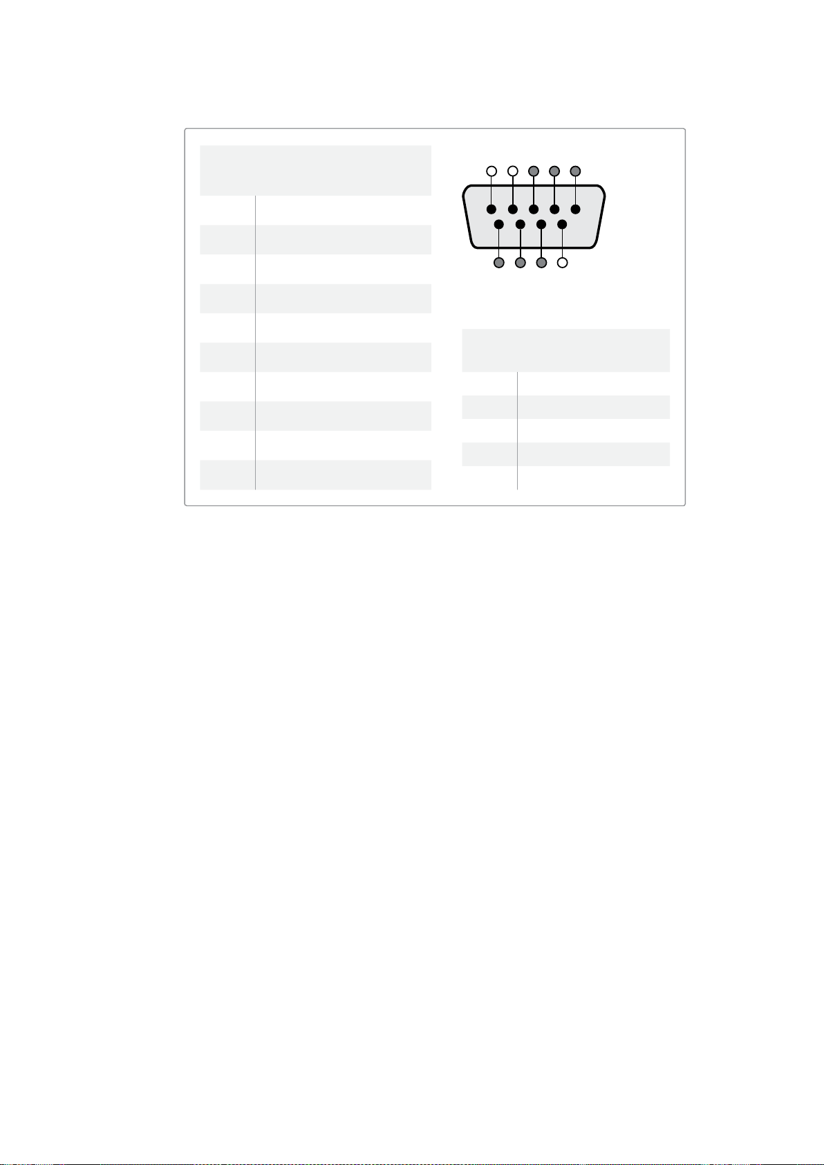
332Ottimizzare l’angolo di visuale
Ottimizzare l’angolo di visuale
Se installi SmartView Duo, SmartView HD o SmartScope in alto su un rack, è consigliabile
invertire fisicamente gli schermi LCD per ottenere un angolo di visuale ottimale. Le immagini
sugli schermi LCD ruotano automaticamente nella posizione corretta in base al movimento
rilevato. Per smontare e rimontare la placca dal retro del dispositivo è necessario un cacciavite
Pozidriv 2. Si tratta di una procedura semplice che non richiede l’apertura del vano posteriore.
La istruzioni qui sotto spiegano come invertire l’unità mantenendo il logo Blackmagic Design
nella direzione corretta sulla placca. È necessario un cacciavite Pozidriv 2.
1 Rimuovi le viti dal lato superiore, inferiore, destro e sinistro della placca. SmartView Duo
e SmartScope Duo 4K hanno 10 viti; SmartView HD ne ha 18.
2 Solleva la placca dal retro del dispositivo come illustrato sotto.
3 Inverti il retro del dispositivo.
4 Reinserisci la placca sul retro del dispositivo invertito.
5 Reinserisci le viti precedentemente rimosse.
Ora puoi installare SmartView o SmartScope sul rack. Una volta avvitato sul rack, SmartView
continua a visualizzare l’angolo ottimale anche se viene urtato poiché non ci sono manopole
esterne o controlli esposti.
SmartView Duo e SmartScope Duo 4K
Configurazione tally
Pin Funzione
1 Monitor 1 Rosso
2 Monitor 1 Verde
3 Monitor 1 Blu
4 Ground
5 Ground
6 Ground
7 Monitor 2 Rosso
8 Monitor 2 Verde
9 Monitor 2 Blu
SmartView HD e SmartView 4K
Configurazione tally
Pin Funzione
1 Rosso
2 Verde
3 Blu
4 Ground
5 4 3 2 1
9 8 7 6
Porta tally di SmartView
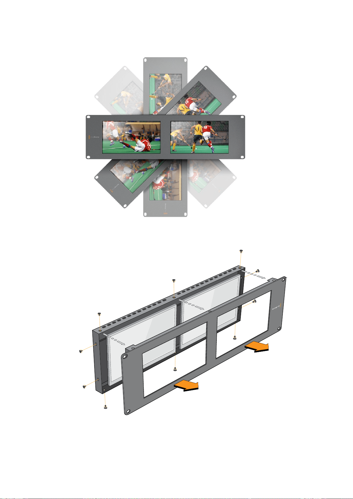

334Informazioni per gli sviluppatori (English)
Informazioni per gli sviluppatori (English)
Developing Custom Software Using Blackmagic Design Hardware
The Blackmagic SmartView Ethernet Protocol allows developers to remotely control Blackmagic
SmartView and SmartScope hardware with their own custom software. The Blackmagic
SmartView Ethernet Protocol is a text-based status and control protocol.
Downloading the Free SmartView EthernetProtocol
The Blackmagic SmartView Ethernet Protocol is free. It is included in this SmartView &
SmartScope manual and can be downloaded from www.blackmagicdesign.com/it/support
Joining the Blackmagic Design Developer List
The Blackmagic Developer mailing list is designed for technical questions regarding
technologies used by Blackmagic Design, e.g., QuickTime, Core Media, DirectShow, codecs,
APIs, SDKs, etc. The free mailing list is a forum where developers can discuss ideas and
problems with other developers. Any subscriber may reply and the Blackmagic Design
engineers may also respond when appropriate. You can subscribe to the mailing list at:
http://lists.blackmagicdesign.com/mailman/listinfo/bmd-developer
In some cases, we might request a brief outline of the software you are developing if it is not
immediately obvious from your domain name that your organization develops video software.
Please don’t take offence as we’re simply trying to keep the list free of spam and viruses as
well as end-user customers asking non-development questions, employment agents or sales
people trying to promote products on the list. The list is just for developers.
Contacting Blackmagic Design DeveloperAssistance
You can also contact us via developer@blackmagicdesign.com if you have any developer
related questions or wish to ask questions off the list.
Blackmagic 2K Format – Overview
Blackmagic Design products support 3G-SDI video, which allows twice the data rate of
traditional HD-SDI video. We thought it would be a really nice idea to add 2K film support,
via 3G-SDI technology, so we could simplify feature film workflows. With the popularity of
Blackmagic Design editing systems worldwide, now thousands of people can benefit from
a feature film workflow revolution.

335Informazioni per gli sviluppatori (English)
This information includes everything product developers need to know for building native 2K
SDI equipment. Of course, all Blackmagic products can be updated, so if the television industry
adopts an alternative SDI-based film standard, we can add support for that too!
Frame Structure
Transmitted at 23.98, 24 or 25 frames per second as a Progressive Segmented Frame.
Active video is 2048 pixels wide by 1556 lines deep.
Total lines per frame : 1650
Active words per line are 1535. One word consists of a 10-bit sample for each of the
four data streams, i.e., a total of 40 bits. See the diagram named Blackmagic 2K Format
- Data Stream Format.
Total active lines : 1556
Total words per line : 1875 for 23.98/24Hz and 1800 for 25Hz.
Fields per frame : 2, 825 lines each
Active lines located on lines 16-793 (field 1) and 841-1618 (field 2).
Transport Structure
Based on SMPTE 372M Dual Link mapping and SMPTE 425M-B support for mapping
SMPTE 372M into a single 3 Gb/s link.
Timing reference signals, line number and line CRC insertion is the same as above.
During active video, 10-bit Red, Green and Blue data is sent in the following sequence:
Optional ancillary data is inserted into both virtual interfaces.
At present, only audio data is included: as per standard HD audio insertion (SMPTE
S299M) the audio data packets are carried on data stream two and audio control
packets are carried on data stream one.
Data stream 1: Green_1, Green_2, Green_3, Green_5...Green_2047
Data stream 2: Blue_1, Blue_2, Green_4, Blue_5...Green_2048.
Data stream 3: Red_1, Blue_3, Blue_4, Red_5...Blue_2048.
Data stream 4: Red_2, Red_3, Red_4, Red_6...Red_2048.
Blackmagic 2K Format –Vertical Timing Reference
This diagram shows the vertical timing details with line numbers and Field, Vertical and
Horizontal bits for the Timing Reference Signal codes.
Field 1 Active
F
1 0 0 0 0 0 0 0 0 0 0 0
V
1 1 1 1 1 1 0 0 0 0 1 1
LINE #
1650 1 2 ... 14 15 16 ... 792 793 ... 825
Field 2 Active
F
0 1 1 1 1 1 1 1 1 1 1 1
V
1 1 1 1 1 1 0 0 0 0 1 1
LINE #
825 826 827 ... 839 840 841 ... 1617 1618 ... 1650
336Informazioni per gli sviluppatori (English)
Blackmagic 2K Format –DataStream Format
This diagram shows the data stream formats around the optional ancillary data section of the
horizontal line. Note that each active pixel takes up three samples.
Data Stream 1
G2041
G2042
G2043
G2045
G2046
G2047
EAV(3FFh)
EAV(000h)
EAV(000h)
EAV(XYZh)
LN0
LN1
CRC0
CRC1
ANC/Audio Data
SAV(3FFh)
SAV(000h)
SAV(000h)
SAV(XYZh)
G1
G2
G3
G5
Data Stream 2
B2041
B2042
G2044
B2045
B2046
G2048
EAV(3FFh)
EAV(000h)
EAV(000h)
EAV(XYZh)
LN0
LN1
CRC0
CRC1
ANC/Audio Data
SAV(3FFh)
SAV(000h)
SAV(000h)
SAV(XYZh)
B1
B2
G4
B5
Data Stream 3
R2041
B2043
B2044
R2045
B2047
B2048
EAV(3FFh)
EAV(000h)
EAV(000h)
EAV(XYZh)
LN0
LN1
CRC0
CRC1
040
…
040
SAV(3FFh)
SAV(000h)
SAV(000h)
SAV(XYZh)
R1
B3
B4
R5
Data Stream 4
R2042
R2043
R2044
R2046
R2047
R2048
EAV(3FFh)
EAV(000h)
EAV(000h)
EAV(XYZh)
LN0
LN1
CRC0
CRC1
200
…
200
SAV(3FFh)
SAV(000h)
SAV(000h)
SAV(XYZh)
R2
R3
R4
R6
Word#
23.98/24 PsF
1870
1871
1872
1873
1874
1875
1
2
3
4
5
6
7
8
9
…
335
336
337
338
339
340
341
342
343
Word#
25 PsF
1795
1796
1797
1798
1799
1800
1
2
3
4
5
6
7
8
9
…
260
261
262
263
264
265
266
267
268

337Informazioni per gli sviluppatori (English)
Blackmagic SmartView Ethernet Protocol v1.3
Summary
The Blackmagic SmartView Ethernet Protocol is a text-based status and control protocol, very
similar in structure to the Videohub protocol, that is accessed by connecting to TCP port 9992
on a SmartView or SmartScope device.
Upon connection, the SmartView or SmartScope device sends a complete dump of the state
of the device. After the initial dump, state changes are sent asynchronously.
The device sends information in blocks which have an identifying header, followed by a colon.
A block can span multiple lines and is terminated by a blank line.
To be resilient to future protocol changes, clients should ignore blocks they do not recognize,
up to the trailing blank line. Within recognized blocks, clients should ignore lines they do not
recognize.
Version 1.3 of the Blackmagic SmartView Ethernet
Protocol was released with SmartView 1.3 software.
Protocol Preamble
The first block sent by the SmartView Server is always the protocol preamble:
PROTOCOL PREAMBLE:↵
Version: 1.3 ↵
↵
The version field indicates the protocol version. When the protocol is changed in a compatible
way, the minor version number will be updated. If incompatible changes are made, the major
version number will be updated.
Device Information
The next block contains general information about the connected SmartView or
SmartScope device.
SMARTVIEW DEVICE:↵
Model: SmartView Duo↵
Hostname: stagefront.studio.example.com↵
Name: StageFront↵
Mo nitor s: 2↵
Inverted: false↵
↵
This example shows the output for a SmartView Duo device, which has two LCDs.
The INVERTED flag indicates whether the device has detected that it has been mounted in an
inverted configuration to optimize LCD viewing angle.
Legend
↵ carriage return
… and so on

338Informazioni per gli sviluppatori (English)
Network Configuration
The next block shows the TCP/IP networking configuration:
NETWORK:↵
Dynamic IP: true↵
Static address: 192.168.2.2↵
St atic netm as k: 255.255.255.0↵
St atic gatew ay: 192.168.2.1↵
C u rr e nt ad d r e ss: 192.168.1.101↵
C u rr e nt netm a sk: 255.255.255.0↵
C u rr e nt g ate w ay: 192.168.1.1↵
↵
The network settings prefixed with CURRENT show the active TCP/IP settings, and are read-
only. The CURRENT settings reflect either the DHCP or Static configuration, depending on the
DYNAMIC IP flag.
Changing Networking Settings
The network can be configured to use either DHCP or a static configuration. To enable DHCP:
NETWORK:↵
Dynamic IP: true↵
↵
To set a fixed IP address, supply all static parameters, thus:
NETWORK:↵
Dynamic IP: false↵
Static address: 192.168.2.2↵
St atic netm as k: 255.255.255.0↵
St atic gatew ay: 192.168.2.1↵
↵
The parameters with the CURRENT prefix are read-only, and show the active configuration,
regardless of the static or dynamic setting.
Changing the device name, or any network settings, will cause the IP connection to be
dropped. The device will restart its networking and advertise its new name on the network.
Changing Monitor Settings
The display settings for each monitor are specified individually. One or more parameters can
be modified at the same time and multiple settings can be supplied in one block.
The valid range for numeric values is 0-255. The CONTRAST and SATURATION properties are
zero-centered, so the normal value is 127, such that the displayed picture is the same as the
original. A value greater than 127 in either channel will cause the contrast or saturation to be
increased, and similarly a value less than 127 will cause a decrease.
For example, to set the brightness to 50% and desaturate the image to Black & White:
MONITOR A:↵
Brightness: 127↵
Saturation: 0↵
↵

339Informazioni per gli sviluppatori (English)
Displaying SD in 16:9
The following command sets standard definition video to display in 16:9:
MONITOR A:↵
WidescreenSD: ON↵
Displaying SD in 4:3
The following command sets standard definition video to display in 4:3:
MONITOR A:↵
WidescreenSD: OFF↵
Identification and Tally Settings
The Identify flag is transient, and will cause a white border to be displayed around the entire
picture for a duration of 15 seconds, after which it will be reset. This feature is primarily aimed at
identifying which monitor is currently being configured when it is mounted in a rack comprising
multiple units. To turn on:
MONITOR A:↵
Ide ntify: tr u e↵
↵
The IDENTIFY border will temporarily override any other border setting in effect.
The BORDER property can be used to programmatically set the soft Tally colored borders to
one of the primary colors: RED, GREEN, BLUE, WHITE or NONE. This setting can be overridden
by the electrical Tally signals at the DB-9 input on the device itself. For example, to set the soft
Tally to green:
MONITOR B:↵
Border: green↵
↵
The hard wired tally will always override the soft tally. The full state report will always show the
current valid border.
SmartScope Settings
On SmartScope Duo 4K, each monitor can be set to display a different scope. The values for
activating specific scopes are mapped as follows:
AudioDbfs
AudioDbvu
Histogram
ParadeRGB
ParadeYUV
Picture (This is the same as Video Monitor)
Vector100
Vector75
WaveformLuma
MONITOR A:↵
ScopeMode: Picture↵
↵
In the example above, Monitor A has been set as a video monitor.

340Informazioni per gli sviluppatori (English)
Displaying SD in 16:9
The set Video Monitor mode to display standard definition video in 16:9:
MONITOR A:↵
ScopeMode: Picture↵
WidescreenSD: ON↵
Displaying SD in 4:3
To set Video Monitor mode to display standard definition video in 4:3:
MONITOR A:↵
ScopeMode: Picture↵
WidescreenSD: OFF↵
When setting one of SmartScope Duo 4K’s monitors to audio metering, you can also select
which channels to show. The values for selecting which audio channels are mapped in the
following way:
0: Channels 1 and 2
1: Channels 3 and 4
2: Channels 5 and 6
3: Channels 7 and 8
4: Channels 9 and 10
5: Channels 11 and 12
6: Channels 13 and 14
7: Channels 15 and 16
MONITOR B:↵
ScopeMode: AudioDbvu↵
AudioChannel: 0↵
↵
In the example above, Monitor B has been selected to display Audio Metering in Dbvu with
audio channels 1 and 2 selected for the phase meter.
Selecting LUTs for SmartView 4K
To select 3D LUTs using SmartView 4K:
MONITOR A:↵
LUT: 0 LUT 1
1 LUT 2
NONE DISABLE
↵
↵

341Assistenza
Assistenza
Assistenza clienti
Ci sono quattro opzioni per ricevere assistenza
1 Visita www.blackmagicdesign.com/it/support per le note di supporto più recenti.
2 Contatta il tuo rivenditore Blackmagic Design per gli aggiornamenti tecnici Blackmagic
Design più recenti e per ottenere assistenza immediata. I rivenditori ti forniscono
opzioni di assistenza su misura in base alle esigenze del tuo flusso di lavoro.
3 Inviaci un’email con le tue domande cliccando su Invia una email sulla pagina
www.blackmagicdesign.com/it/support
4 Chiama uno dei centri assistenza Blackmagic Design. Per trovare quello più vicino a te,
clicca su Trova un team di supporto in basso alla pagina Supporto.
Ti preghiamo di fornirci informazioni dettagliate in merito ai problemi tecnici e alle specifiche di
sistema per consentirci di risolvere il problema nel minor tempo possibile.
342Normative e sicurezza
Normative e sicurezza
Indicazioni sulle normative
Smaltimento di apparecchiature elettriche e elettroniche nell'Unione Europea.
Questo simbolo indica che il prodotto non deve essere scartato insieme agli altri rifiuti,
ma consegnato a uno degli appositi centri di raccolta e riciclaggio. La raccolta e lo
smaltimento differenziato corretto di questo tipo di apparecchiatura evita lo spreco di
risorse e contribuisce alla sostenibilità ambientale e umana. Per tutte le informazioni sui
centri di raccolta e riciclaggio, contatta gli uffici del tuo comune di residenza o il punto
vendita presso cui hai acquistato il prodotto.
Questo dispositivo è stato testato, e dichiarato conforme ai limiti relativi ai dispositivi
digitali di Classe A, ai sensi dell'articolo 15 del regolamento FCC. Talilimiti sono stati
stabiliti con lo scopo di fornire protezione ragionevole da interferenze dannose in
ambienti commerciali. Questo apparecchio genera, usa e può irradiare energia a
radiofrequenza e, se non è installato o usato in conformità alle istruzioni, può causare
interferenze dannose che compromettono le comunicazioni radio. Operare questo
prodotto in ambienti residenziali può causare interferenze dannose, nella cui evenienza
l'utente dovrà porvi rimedio a proprie spese.
Il funzionamento è soggetto alle due condizioni seguenti:
1 Questo dispositivo non deve causare interferenze dannose.
2 Questo dispositivo deve accettare eventuali interferenze ricevute, incluse le
interferenze che possono causare un funzionamento indesiderato.
Indicazioni di sicurezza
Questo dispositivo deve essere connesso a una presa di corrente con messa a terra.
Per ridurre il rischio di scosse elettriche, evitare di esporre il dispositivo a gocce
o spruzzi.
Questo dispositivo è adatto all'uso nei luoghi tropicali con una temperatura ambiente
non superiore ai 40ºC.
Lasciare uno spazio adeguato intorno al prodotto per consentire sufficiente
ventilazione.
Se il dispositivo è installato su rack, assicurarsi che i dispositivi adiacenti non ostacolino
la ventilazione.
Le parti all'interno del dispositivo non sono riparabili dall'utente. Contattare il personale
qualificato di un centro Blackmagic Design per le operazioni di manutenzione.
Usare il dispositivo a un'altitudine non superiore a 2000 m sopra il livello del mare.
Questo prodotto ospita una porta per connettere ricetrasmettitori ottici SFP. Usare solo
moduli SFP Laser, Class 1.
Moduli SFP consigliati da Blackmagic Design:
3G-SDI: PL-4F20-311C
6G-SDI: PL-8F10-311C
343Garanzia
Avvertenze per il personale autorizzato
Scollegare l’alimentazione da entrambe le prese prima di effettuare la
manutenzione!
Attenzione - Fusione bipolare/neutra
L'alimentatore all'interno di questo dispositivo ha un fusibile nei conduttori di
linea e di neutro, ed è idoneo alla connessione al sistema di distribuzione di
energia IT in Norvegia.
Garanzia
Garanzia limitata di un anno
Blackmagic Design garantisce che questo prodotto è fornito privo di difetti nei materiali e nella
manifattura per un periodo di un anno a partire dalla data d'acquisto. Durante il periodo di garanzia
Blackmagic Design riparerà o, a sua scelta, sostituirà tutti i componenti che risultino difettosi
esonerando il Cliente da costi aggiuntivi, purché i componenti vengano restituiti dal Cliente.
Per ottenere l'assistenza coperta dalla presente garanzia, il Cliente deve notificare Blackmagic
Design del difetto entro il periodo di garanzia. Il Cliente è responsabile del costo di imballaggio
e di spedizione del prodotto al centro di assistenza indicato da Blackmagic Design, con spese di
spedizione prepagate. Il costo include spedizione, assicurazione, tasse, dogana, e altre spese
pertinenti alla resa del prodotto a Blackmagic Design.
Questa garanzia perde di validità per danni causati da utilizzo improprio, o da manutenzione e
cura inadeguate del prodotto. Blackmagic Design non ha obbligo di assistenza e riparazione sotto
garanzia per danni al prodotto risultanti da: a) precedenti tentativi di installazione, riparazione o
manutenzione da personale non autorizzato, ovvero al di fuori del personale Blackmagic Design,
b) precedenti usi impropri o tentativi di connessione ad attrezzatura incompatibile al prodotto,
c)precedente uso di parti o ricambi non originali Blackmagic Design, o d) precedenti modifiche o
integrazione del prodotto ad altri prodotti, con il risultato di rendere la riparazione più difficoltosa o
di allungare le tempistiche di eventuali ispezioni atte alla riparazione. LA PRESENTE GARANZIA DI
BLACKMAGIC DESIGN SOSTITUISCE QUALSIASI ALTRA GARANZIA, ESPLICITA O IMPLICITA.
BLACKMAGIC DESIGN E I SUOI FORNITORI ESCLUDONO QUALSIASI ALTRA GARANZIA IMPLICITA
DI COMMERCIABILITÀ O DI IDONEITÀ AD UN USO SPECIFICO. L'INTERA RESPONSABILITÀ DI
BLACKMAGIC DESIGN E L'UNICO ESCLUSIVO RICORSO DELL'UTENTE PER QUALSIASI DANNO
ARRECATO DI NATURA INDIRETTA, SPECIFICA, ACCIDENTALE O CONSEQUENZIALE, ANCHE
QUALORA BLACKMAGIC DESIGN FOSSE STATA AVVERTITA DELLA POSSIBILITÀ DI TALI DANNI,
È LA RIPARAZIONE O LA SOSTITUZIONE DEI PRODOTTI DIFETTOSI. BLACKMAGIC DESIGN NON
SI ASSUME ALCUNA RESPONSABILITÀ PER QUALSIASI USO ILLEGALE DEL DISPOSITIVO DA
PARTE DEL CLIENTE. BLACKMAGIC DESIGN NON SI ASSUME ALCUNA RESPONSABILITÀ PER
DANNI DERIVANTI DALL'USO DI QUESTO PRODOTTO. IL CLIENTE UTILIZZA QUESTO PRODOTTO
A PROPRIO RISCHIO.
© Copyright 2018 Blackmagic Design. Tutti i diritti riservati. ‘Blackmagic Design’, ‘DeckLink’, ‘HDLink’, ‘Workgroup Videohub’,
‘Multibridge Pro’, ‘Multibridge Extreme’, ‘Intensity’ and ‘Leading the creative video revolution’ sono marchi registrati negli Stati
Uniti e in altri Paesi. Altri nomi di prodotti e aziende qui contenuti possono essere marchi dei rispettivi proprietari.


Português
Bem-vindo!
Esperamos que você compartilhe do nosso sonho de transformar a indústria televisiva em uma
indústria verdadeiramente criativa, permitindo que todos tenham acesso a vídeos da mais alta
qualidade.
O monitoramento de vídeo é necessário em todas as partes de uma instalação e os monitores
SmartView são opções ideais. O SmartView 4K possui uma tela LCD com 4K nativo para o
monitoramento de vídeos Ultra HD em resolução máxima, além de um gabinete elegante de
6U com um painel de controle que permite alterar as configurações rapidamente. O SmartView
HD inclui uma tela LCD de 17” em um gabinete para rack de 6U com menos de uma polegada
de espessura. Já o SmartView Duo inclui duas sofisticadas telas LCD de 8” completamente
independentes em um gabinete para rack de 3U com menos de uma polegada de espessura.
O SmartScope Duo 4K conta com duas telas LCD de 8” independentes com funcionalidade
para escopo de forma de onda, permitindo que você monitore seus níveis de vídeo com
agilidade. Todos os monitores SmartView são compatíveis com vídeos SD, HD e 2K via 3G-SDI.
O SmartScope Duo 4K e o SmartView 4K também são compatíveis com Ultra HD 4K via 6G-SDI
e 12G-SDI respectivamente!
O monitoramento de vídeo foi desenvolvido para uso imediato e nosso software Blackmagic
SmartView fornece ao usuário uma ferramenta de configuração fácil e intuitiva.
Este manual de instrução contém todas as informações necessárias para instalar seu
SmartView e SmartScope, embora seja aconselhável pedir ajuda a um assistente técnico se
não tiver certeza sobre os endereços IP ou se não entender bem sobre redes de computador.
OSmartView e SmartScope são fáceis de instalar, mas há algumas preferências um pouco
mais técnicas que você pode precisar configurar após a instalação. Ela deve levar cerca de
5minutos para ser concluída.
Por favor, visite nosso site www.blackmagicdesign.com/br eclique na página de suporte para
baixar as últimas atualizações deste manual e do software SmartView. Por fim, registre seu
dispositivo ao baixar as atualizações de software para que possamos mantê-lo informado
quando lançarmos novos programas. Estamos sempre trabalhando com novos recursos e
aprimoramentos, então gostaríamos muito de ouvir a sua opinião!
Grant Petty
Diretor Executivo da Blackmagic Design

Índice
SmartView & SmartScope
Instruções Preliminares 347
SmartView e SmartScope 347
Conectar Fontes de Vídeo 348
Conectar Computador 348
Instalar Blackmagic SmartView Setup 349
Usar Blackmagic SmartView Setup 350
Atualizar o Software 350
Ajustar Configurações do Monitor 350
Usar SmartView 4K 353
Blackmagic SmartView 4K 353
Botões do Painel de Controle 354
Carregar LUTs 3D Usando Blackmagic SmartView Setup 356
Usar SmartScope Duo 4K 357
O que é Blackmagic SmartScope? 357
Display para Monitoramento de Vídeo 357
Display em Forma de Onda 358
Display em Vetorscópio 359
Display em Padrões 361
Display em Histograma 362
Display com Medição de Áudio 363
Conectar a uma Rede 364
Ethernet Direta 365
Switch de Rede Ethernet 365
Ajustar Configurações de Rede 367
Configurações de Rede 367
Adicionar um Monitor Blackmagic 368
Usar Sinalização 369
Conexões dos Pinos da Porta de Sinalização 369
Otimizar o Ângulo de Visualização 370
Informações para Desenvolvedores 372
Blackmagic 2K Format – Visão Geral 372
Blackmagic 2K Format – Referência de Cronometragem Vertical 373
Blackmagic 2K Format – Formato de Fluxo de Dados 374
Blackmagic SmartView Ethernet Protocol v1.3 375
Ajuda 379
Informações Regulatórias e de Segurança 380
Garantia 381

Instruções Preliminares
SmartView e SmartScope
Os monitores SmartView são ideais para qualquer instalação que necessite de monitoramento
baseado em rack. Para instalar e começar a usá-los, basta conectá-los à energia e a uma fonte SDI!
O SmartView 4K possui um LCD 4K de 15.6” para o monitoramento de vídeos SD, HD ou Ultra HD na
sua resolução nativa de 3840x2160 pixels. Os botões no painel de controle frontal permitem
selecionar entradas com facilidade, bem como ajustar o brilho da tela, verificar ruídos no canal azul,
visualizar informações de apagamento, aplicar LUTs 3D e muito mais.
O SmartView HD possui um LCD HD de 17”, perfeito para um monitoramento em resolução Full HD
confiável.
O SmartView Duo inclui dois monitores para a exibição simultânea de sinais de vídeo diferentes.
Assim, um monitor pode exibir um sinal YUV 4:2:2 enquanto o outro recebe um sinal RGB 4:4:4, por
exemplo. Ou, um monitor pode exibir NTSC enquanto o outro exibe PAL. Há muitas combinações
possíveis, mas todas são tão simples quanto conectar um único cabo SDI a cada monitor!
O SmartScope Duo 4K tem os mesmos recursos que o SmartView Duo, e ainda poder ser usado
para exibir forma de onda, vetorscópio e outros escopos populares para o monitoramento de níveis
de áudio e vídeo em tempo real. E mais, você obtém suporte completo para Ultra HD 4K!
Todas as conexões de entrada SDI nos monitores SmartView e SmartScope são compatíveis com
detecção automática de vídeos SD, HD ou 3G-SDI, assim como 2K. O SmartView 4K também
detecta Ultra HD, incluindo formatos como 2160p60 via 12G-SDI. O SmartScope Duo 4K inclui
detecção automática de vídeos Ultra HD 4K via 6G-SDI.
Caso queira ajustar remotamente as configurações de múltiplos dispositivos SmartView
eSmartScope a partir de um único computador, basta conectá-los juntos via Ethernet. Ou seja, você
não precisará correr para cada unidade com um computador e cabo USB toda vez que quiser
fazer ajustes.
Essas são as informações básicas para você poder começar! Por favor, continue lendo para mais
detalhes sobre como conectar o SmartView e SmartScope, configurar os parâmetros do monitor no
Blackmagic SmartView Setup e conectar a uma rede.
SmartView 4K SmartView HD
SmartView Duo SmartScope Duo 4K
347Instruções Preliminares
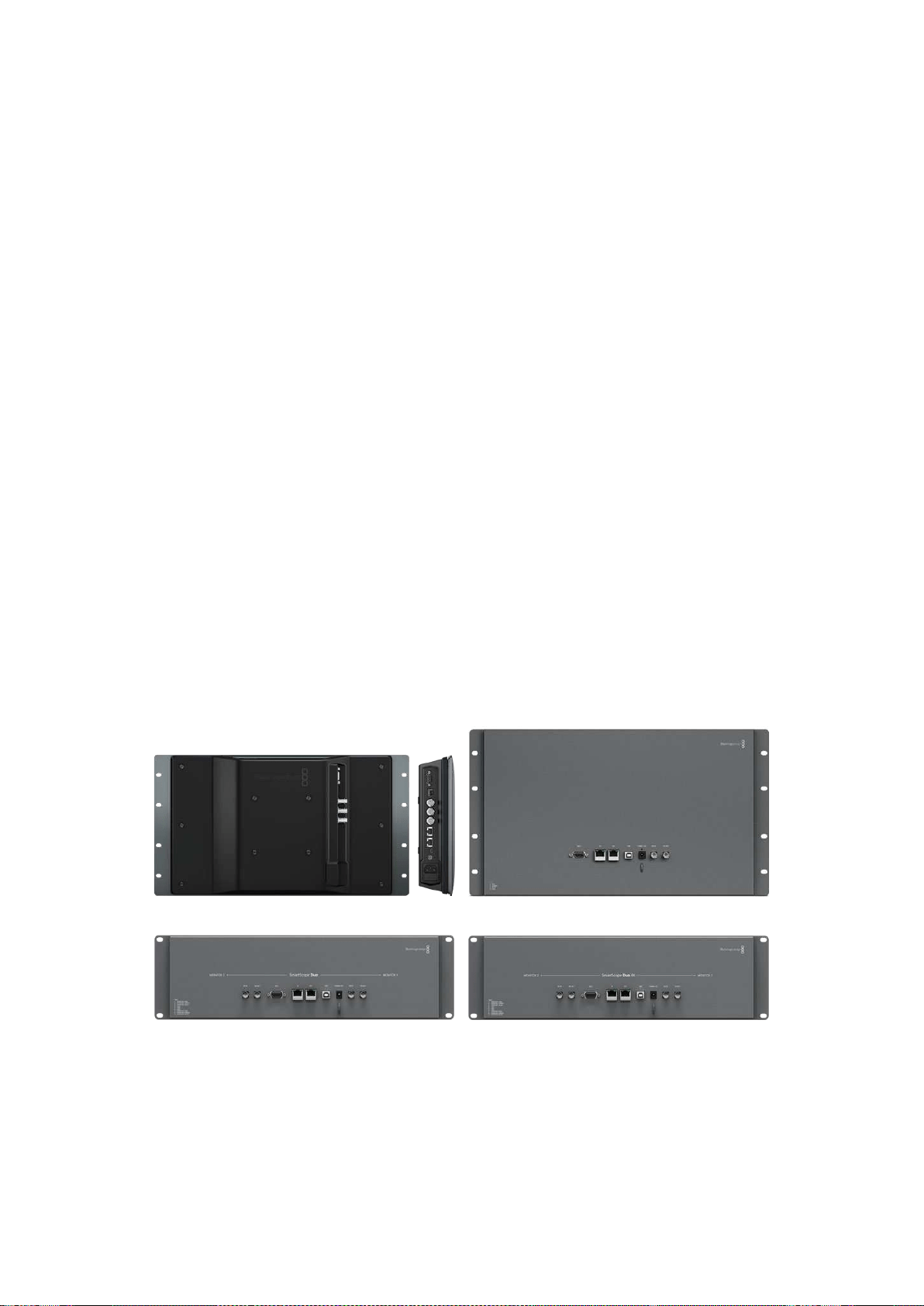
Conectar Fontes de Vídeo
Os monitores SmartView e SmartScope contam com conectores BNC comuns para conexão com
equipamentos SDI, incluindo switchers, câmeras, placas de captura, decks e gravadores de disco.
Como Obter uma Imagem
É muito fácil exibir o seu vídeo! Basta ligar o dispositivo e conectar sua fonte de vídeo a uma entrada
SDI. Logo em seguida, seu video deve estar visível. Os sinais SD, HD e 2K são automaticamente
detectados pelas conexões da entrada SDI e saída loop through. OSmartView 4K e SmartScope
Duo 4K também detectam Ultra HD 4K.
Quando nenhum vídeo é recebido pela unidade, a luz de fundo é desligada para economizar
energia até que o próximo sinal válido seja recebido.
Monitores Montados em Cascata
Cada monitor SmartView e SmartScope tem sua própria entrada SDI independente, bem como uma
saída loop through, assim você pode montar múltiplos monitores em cascata para exibir o mesmo
sinal de entrada:
1 Ligue a unidade 1. Conecte uma fonte de vídeo a uma entrada SDI. O vídeo
deve aparecer imediatamente.
2 Ligue a unidade 2. Conecte um cabo SDI de uma saída loop da unidade 1 a
uma entrada SDI da unidade 2.
Não há um limite quanto ao número de unidades que você pode montar em cascata.
Caso esteja monitorando em onda de forma usando o SmartScope Duo 4K, é provável que queira
fazer o loop da saída do “Monitor 1” para o “Monitor 2” para que ambos os displays passem a usar o
mesmo sinal de entrada.
Agora que o vídeo está sendo exibido, é possível ajustar as configurações do monitor ou selecionar
os escopos no SmartScope Duo 4K usando o software Blackmagic SmartView Setup, o qual também
pode ser utilizado para carregar LUTs 3D no Blackmagic SmartView 4K.
SmartView 4K SmartView HD
SmartView Duo SmartScope Duo 4K
Conectar Computador
Configure os parâmetros do monitor SmartView ou SmartScope conectando-o ao seu computador
via USB e instalando o Blackmagic SmartView Setup.
348Instruções Preliminares
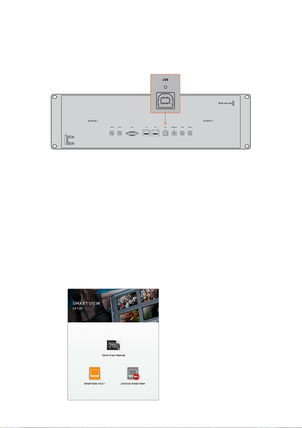
A conexão USB também pode ser usada para atualizações internas do software baixado através do
site da Blackmagic Design. As atualizações do software podem fornecer novos recursos,
compatibilidade com novo hardware e suporte para novos formatos. O software Blackmagic
SmartView Setup opera tanto nos computadores macOS quanto Windows.
Instalar Blackmagic SmartView Setup
O Blackmagic SmartView Setup é executável nas versões Sierra e High Sierra mais recentes do
macOS e nas versões de 64 bits do Windows 8.1 e 10 com os últimos pacotes de serviço (service
packs) instalados. O Blackmagic SmartView Setup pode ser instalado em múltiplos computadores
em rede, se necessário.
O cartão SD fornecido com o SmartView contém o instalador de software, mas recomendamos que
você visite a página www.blackmagicdesign.com/br/support para certificar-se de que tenha
aúltima versão.
Como instalar no macOS:
Abra o cartão SD fornecido, ou baixe a imagem de disco, e dê um clique duplo no ícone de
instalação do SmartView. Uma pasta do SmartView será criada na sua pasta de aplicativos com
oSmartView Setup, assim como um desinstalador para a remoção de versões antigas ao fazer
aatualização e uma pasta de documentos com este manual e outras informações sobre o
SmartView.
Como instalar no Windows:
Abra o cartão SD fornecido, ou o arquivo zip baixado, e dê um clique duplo no instalador do
SmartView. Siga as solicitações na tela para instalar o software.
Para instalação no macOS, inicie o
arquivo SmartView.dmg no cartão SD
fornecido, ou a partir da sua pasta de
downloads, e dê um clique duplo no
ícone de instalação do SmartView.
349Instruções Preliminares
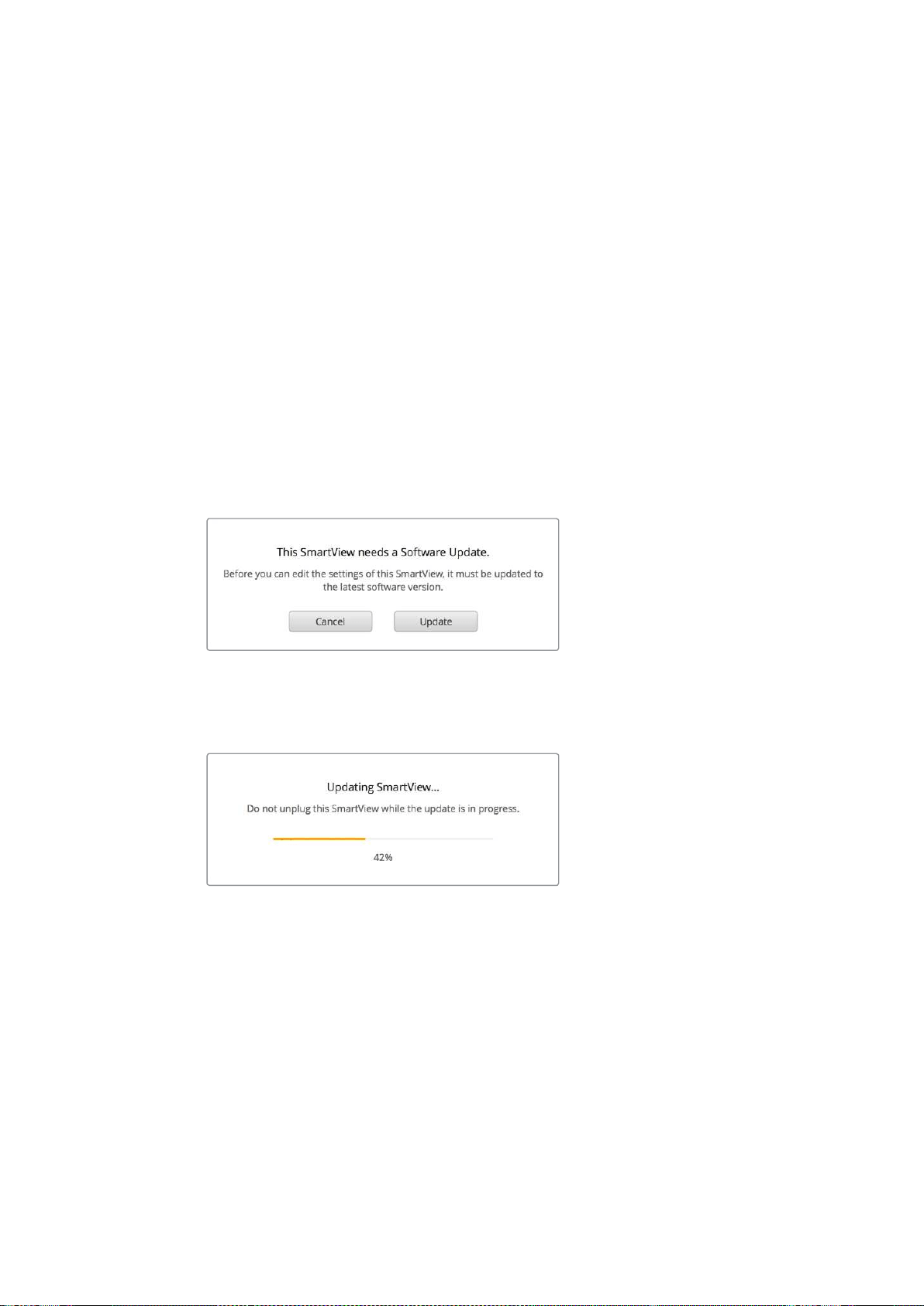
Usar Blackmagic SmartView Setup
Atualizar o Software
Depois de instalar e iniciar o Blackmagic SmartView Setup, clique no ícone de configuração abaixo
do nome do seu monitor. Pode ser que você seja solicitado a atualizar o software interno do seu
SmartView ou SmartScope. Para fazer isto:
1 Conecte seu SmartView ou SmartScope ao computador via USB ou Ethernet
einicie o Blackmagic SmartView Setup.
2 Quando solicitado, basta clicar em “Update”. A atualização deve levar 5
minutos para ser finalizada.
3 A mensagem “This SmartView has been updated” deve aparecer após
conclusão da atualização.
4 Clique em “Close” para fechar.
Se nenhuma atualização de software for necessária, o Blackmagic SmartView Setup abrirá a página
de configurações para seu monitor.
Ao iniciar o SmartView Setup e abrir o ícone de
configuração do seu SmartView ou SmartScope
conectado, esta mensagem aparecerá caso uma
atualização do software interno seja necessária.
A atualização deve levar 5 minutos para ser finalizada.
Ajustar Configurações do Monitor
Imediatamente após ser iniciado, o Blackmagic SmartView Setup procurará por quaisquer unidades
SmartView ou SmartScope conectadas via USB ou Ethernet e as exibirá na sua página inicial. Caso
tenha mais de um monitor Blackmagic conectado à sua rede, clique nos ícones das setas esquerda
e direita em cada lado da página inicial para selecionar o monitor que deseja ajustar. Se o seu
monitor Blackmagic estiver conectado via USB, um ícone de USB aparecerá próximo do nome
do monitor.
Para ajustar as configurações, selecione seu monitor conectado via Ethernet e USB e clique no
ícone de configuração abaixo do nome do monitor. A página de configurações do seu monitor
selecionado abrirá. Quando estiver satisfeito com suas configurações, clique no botão “Save” para
salvá-las e retorne para a página inicial do SmartView Setup.
350Usar Blackmagic SmartView Setup
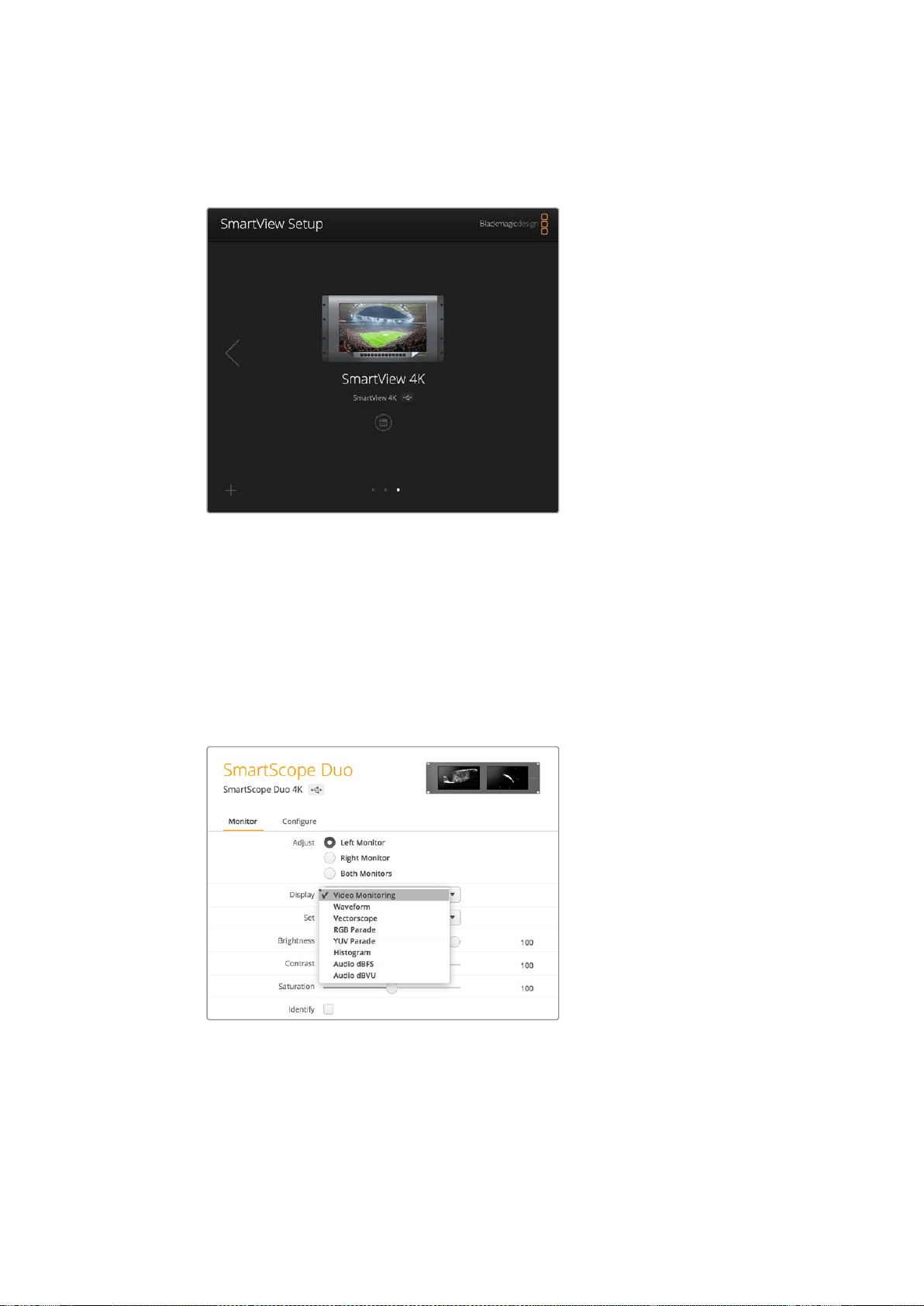
Leia a próxima seção para informações sobre as configurações disponíveis para os monitores
Blackmagic e como usá-las. Para detalhes sobre como configurar os parâmetros de rede usando o
Blackmagic SmartView Setup, consulte a seção ‘Ajustar Configurações de Rede’.
O Blackmagic SmartView Setup procura automaticamente por quaisquer unidades SmartView
e SmartScope conectadas localmente via USB ou através de uma rede. Aoatualizar o
software interno do seu monitor, certifique-se de que o monitor esteja conectado via
USB ou Ethernet. Um ícone de USB aparecerá próximo ao nome do seu monitor.
Configurações do Monitor
Para ajustar as configurações e os displays de cada monitor, eles devem estar conectados via
Ethernet ou USB. Selecione o monitor que deseja configurar clicando nos ícones das setas
esquerda e direita na página inicial do SmartView Setup e, depois, clique no ícone de configuração
abaixo do nome do seu monitor. A página de configurações é personalizada automaticamente para
adequar-se aos recursos compatíveis com seu monitor Blackmagic selecionado.
Com o SmartScope, você pode selecionar entre monitoramento de
vídeo ou escopos a partir do menu suspenso “Display”.
Adjust
Ao usar um SmartScope ou SmartView Duo, escolha o monitor que deseja ajustar selecionando
“Left Monitor” (monitor esquerdo), “Right Monitor” (monitor direito) ou “Both Monitors” (ambos os
monitores) para ajustar os dois ao mesmo tempo. Quando a configuração “Both Monitors” é
habiltada, todos os ajustes de brilho, contraste e saturação são empregados a ambos os monitores
no SmartView Duo e SmartScope.
351Usar Blackmagic SmartView Setup
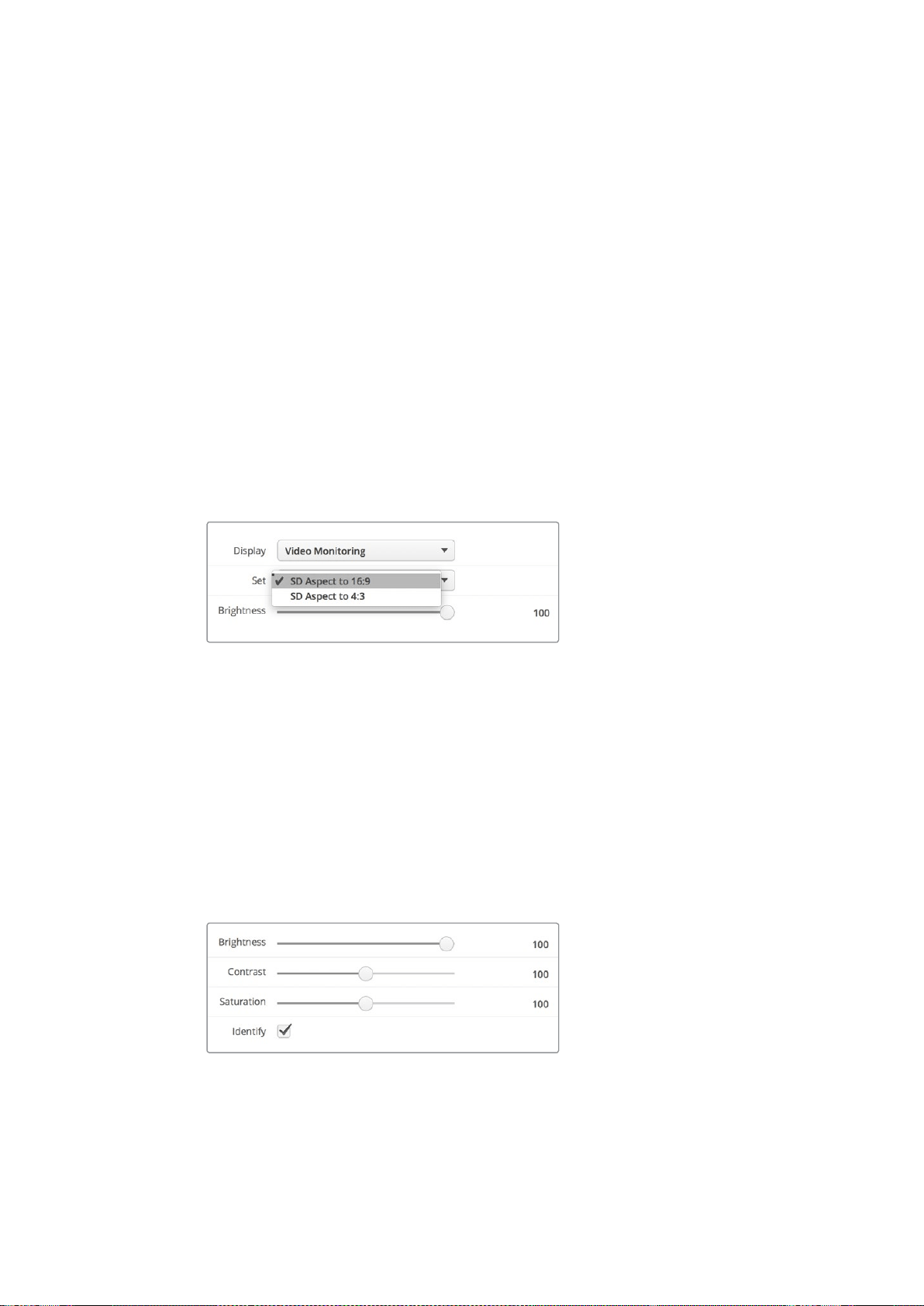
Display
Ao usar um SmartScope, o menu suspenso “Display” fornece escopos selecionáveis. Selecione
“Video Monitoring” caso queira ver apenas a imagem de vídeo.
Set
Ao usar um SmartScope, o menu suspenso “Set” permite que você selecione proporções de tela
4:3ou 16:9 para o display de monitoramento de vídeo quando estiver usando vídeo de definição
padrão. O menu suspenso “Set” fornece opções adicionais para o display selecionado, incluindo
vetorscópio, áudio dBFS e áudio dBVU.
Video Monitoring: Selecione esta opção para visualizar a imagem de vídeo usando as
proporções de tela 4:3 ou 16:9.
Ao visualizar vídeos em definição padrão no formato widescreen anamórfico, opte pela
proporção de tela 16:9. Ao visualizar vídeos em definição padrão no formato tradicional 4:3,
opte pela proporção de tela 4:3.
Vectorscope: Selecione esta opção se sua entrada estiver baseada em sinais de teste de
barras de cor a 100% ou 75%.
Audio dBFS: Selecione o par de canais de áudio para monitorar a fase.
Audio dBVU: Selecione o par de canais de áudio para monitorar a fase.
Configure “SD Aspect to 16:9” quando estiver visualizando
vídeos em definição padrão no formato anamórfico.
Brightness, Contrast, Saturation
Ajuste os deslizadores para aplicar as configurações de brilho, contraste e saturação.
Identify
Quando a caixa de verificação “Identify” estiver habilitada, todos os monitores selecionados na
configuração do Blackmagic SmartView exibirão uma borda branca. Se algumas unidades
SmartView e SmartScope estiverem conectadas via uma rede, esta configuração facilitará
aidentificação visual do monitor selecionado.
Se esta configuração for usada junto com a configuração “Both Monitors”, a borda branca será
exibida em ambos os monitores SmartScope Duo e SmartScope Duo 4K.
Arraste os deslizadores para a esquerda e direita para ajustar as
configurações de brilho, contraste e saturação. Marque a configuração
“Identify” para identificar visualmente o seu monitor selecionado.
352Usar Blackmagic SmartView Setup
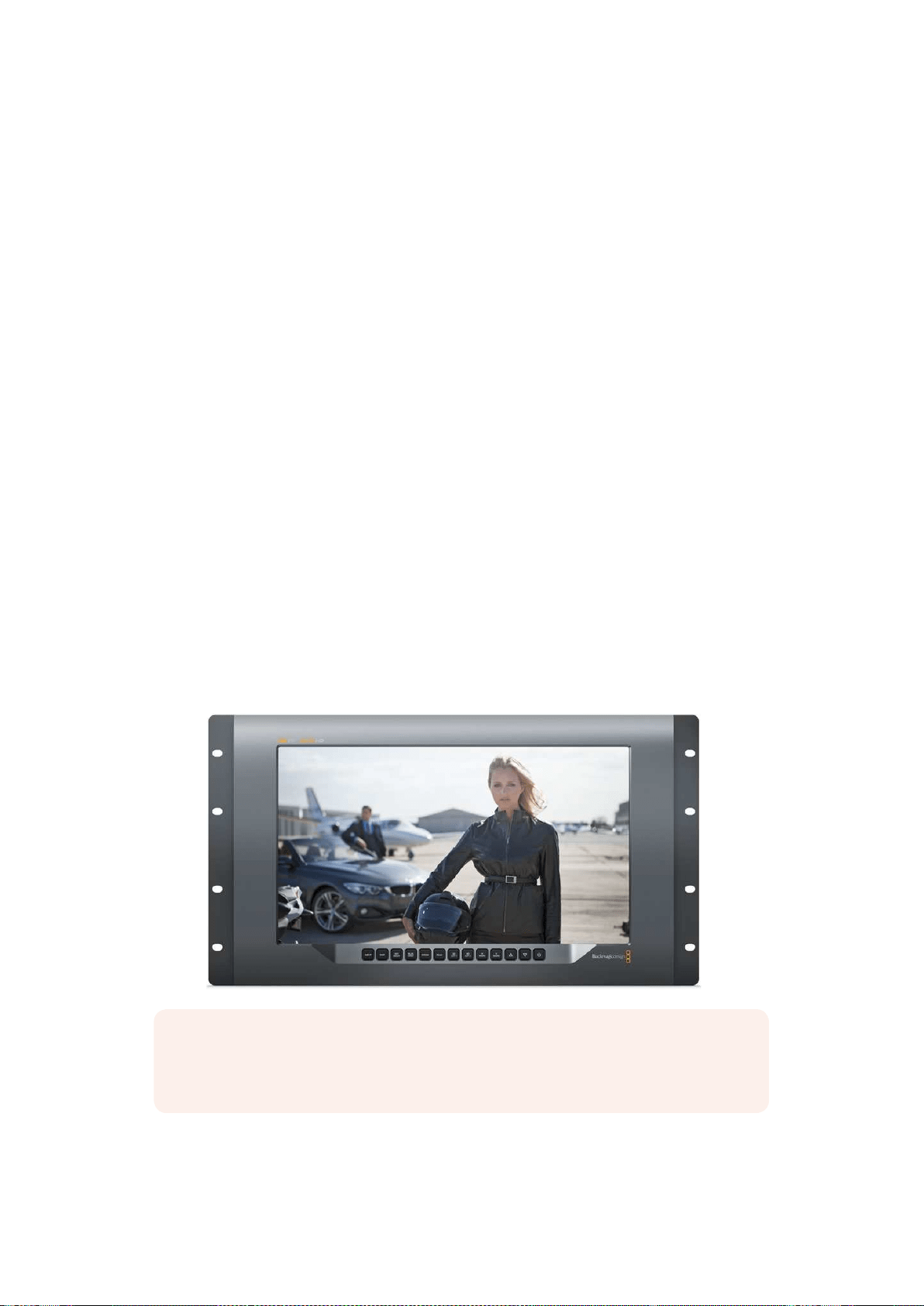
Usar SmartView 4K
Blackmagic SmartView 4K
O SmartView 4K é um monitor broadcast Ultra HD 12G-SDI baseado em rack de 6U para exibição de
conteúdo SD, HD e visualização nativa de vídeos Ultra HD de até 2160p60. Com um display
luminoso e um ângulo de visualização amplo, o SmartView 4K fornece uma imagem absolutamente
clara e expressiva para o monitoramento de cor e foco preciso e é compatível com praticamente
todos os formatos de vídeo.
Desenvolvido para estúdios e ambientes broadcast externos, o SmartView 4K é incrivelmente fácil
de usar. Ele inclui conectores para encaixe lateral e suporte VESA, podendo ser usado em espaços
apertados, fixado na parede ou em braços articulados. O SmartView 4K pode ser operado usando o
painel de controle integrado ou remotamente via Ethernet, se você não tiver acesso ao painel fontal.
As duas entradas 12G-SDI multitaxa permitem que você selecione entre duas fontes SDI e há um
soquete de módulo SFP compatível com SMPTE para adicionar um módulo SDI de fibra óptica e
conectar seu vídeo via fibra óptica! A saída 12G-SDI é fornecida para que você possa alimentar seu
vídeo a outros equipamentos, além de dois conectadores de Ethernet para rede, controle remoto e
saída loop para monitoramento em cascata. Outros conectores incluem uma entrada de sinalização
para produção ao vivo, e uma porta USB para atualizações de software interno.
Você pode até carregar LUTs 3D padrão da indústria com extensão .cube ou LUTs geradas pelo
DaVinci Resolve usando o software de configuração Blackmagic SmartView! Com as LUTs 3D, você
pode conectar seu SmartView 4K diretamente à sua câmera e visualizar seus clipes da maneira mais
próxima possível da gradação final. Os dois níveis de saliência garantem que suas filmagens
mantenham o foco perfeito e, com o suporte para alimentação AC e DC, você tem a opção de
conectar o SmartView 4K a tomadas ou usar uma bateria externa para portabilidade no set.
O SmartView 4K é a solução de monitoramento perfeita para produções portáteis broadcast e de
estúdio exibindo vídeos em SD, HD e Ultra HD na sua resolução nativa de 3840x2160 pixels.
OBSERVAÇÃO Caso esteja conectando alimentação externa através da entrada de
alimentação DC, certifique-se de que sua saída de alimentação externa seja capaz de
fornecer 24 watts a 12 volts.
353Usar SmartView 4K
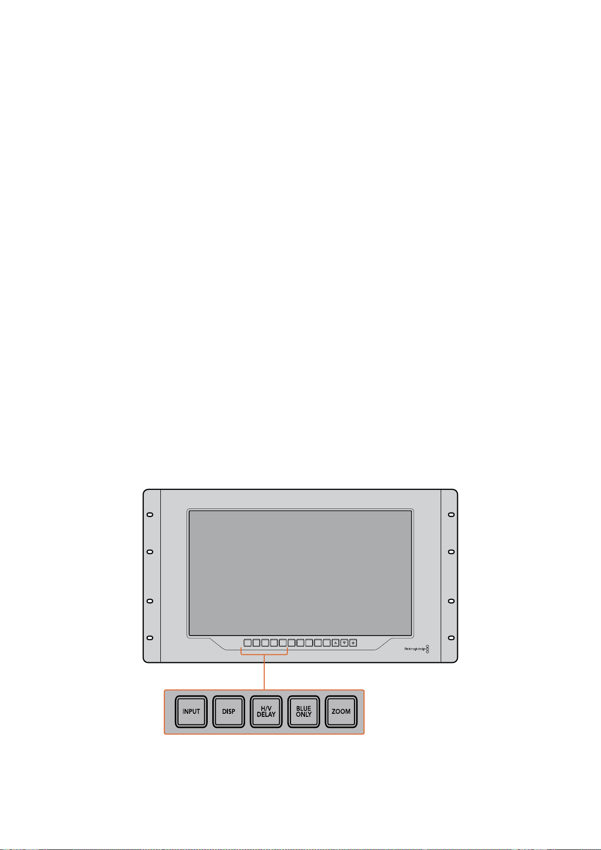
Botões do Painel de Controle
O painel de controle inclui uma fileira de botões para que você possa ajustar rapidamente as
configurações do seu SmartView 4K.
Input
Ao pressionar este botão, é possível percorrer pelos sinais de vídeo conectados às duas entradas
12G-SDI do SmartView e à entrada do módulo SFP de fibra óptica opcional. Se nenhum vídeo
estiver conectado a uma das entradas, o SmartView 4K exibirá uma imagem preta para essa
entrada. Ao alternar entre as entradas, informações sobre o formato da entrada conectada serão
exibidas momentaneamente no canto superior esquerdo do seu monitor.
Disp
O botão “Disp” é usado para ajustar a configuração de brilho na tela LCD do seu SmartView 4K.
Ajuste o brilho pressionando os botões de seta para cima e para baixo. Pressione o botão “Disp”
mais uma vez para fechar a configuração.
H/V Delay
O botão “H/V Delay” permite que você confirme com rapidez a presença de dados ANC embutidos
no sinal de vídeo SDI. Pressione esse botão uma vez para visualizar os dados ANC horizontais e o
pressione novamente para visualizar os dados ANC verticais, comumente usados para dados como
legendagem oculta.
Blue Only
Caso haja ruídos em um sinal de vídeo digital, ele proeminentemente estará dentro do canal
azul. Você pode verificá-los facilmente no seu canal azul pressionando o botão “Blue Only”. Ele
exibe somente o canal azul representado como uma imagem preta e branca. Essa imagem preta
e branca também pode ser usada para assistência ao verificar o foco da câmera.
Zoom
Um jeito de alcançar um foco de câmera nítido é usando o botão “Zoom”. Pressione uma vez para
aplicar o zoom à imagem e você poderá ver claramente se o objeto está em foco. Pressione “Zoom”
novamente para retornar ao tamanho de visualização normal.
INPUT DISP
H/V
DELAY
3D
LUT 1
BLUE
ONLY
ZOOM PEAK
3D
LUT 2
H
MARK
V
MARK
354Usar SmartView 4K
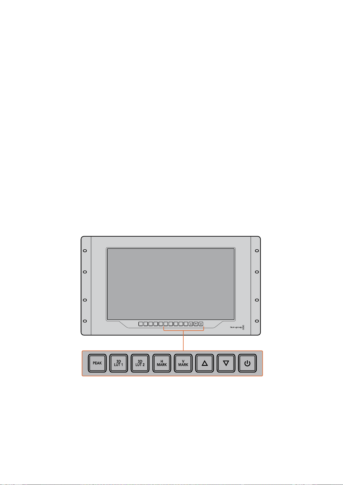
Peak
O foco de câmera pode ser facilmente verificado pressionando o botão “Peak” para habilitar
asaliência. Ele exibe uma borda verde luminosa ao redor dos pontos mais proeminentes na sua
imagem. Há dois niveis de intensidade de saliência, pelos quais você pode percorrer pressionando
subsequentemente o botão “Peak”. Quando as bordas verdes exibem sua intensidade máxima,
você pode ter certeza de que sua câmera está em foco.
3D LUT 1 e 3D LUT 2
Os botões “LUT” permitem que você veja sua imagem usando as LUTs 3D personalizadas geradas
no Blackmagic DaVinci Resolve ou as LUTs no formato padrão de indústria .cube. Pressione o botão
“LUT” uma vez para habilitar a LUT. Pressione novamente para desabilitá-la. Consulte a seção
‘Carregar LUTs 3D Usando Blackmagic SmartView’ para mais informações sobre como usar LUTs 3D
com o SmartView 4K.
H Mark e V Mark
É possível visualizar e editar marcadores de quadro usando os botões “H Mark” e “V Mark”.
Osmarcadores de quadro ajudam a compor filmagens ou manter informações ou gráficos
importantes na área segura da tela. Televisores diferentes exibem um pouco mais ou menos das
extremidades de um sinal de vídeo, então vale a pena visualizar uma área segura. Ela é aseção da
tela que sempre estará visível, independentemente do televisor ou do monitor usado para
visualização.
Para ver marcadores horizontais e verticais, pressione os botões “H Mark” e “V Mark”,
respectivamente. Para editar os marcadores, pressione os respectivos botões novamente para
realçar cada guia. Isto permite que você edite as posições dos marcadores usando os botões de
seta para cima e para baixo. Ao pressionar subsequentemente cada botão, você confirmará suas
novas posições. Se pressionar mais uma vez, você desabilitará os marcadores.
Botões de Seta Para Cima e Para Baixo
Use os botões de seta para cima e para baixo quando estiver editando uma configuração, como
ajustando o brilho do display ou editando as posições do marcador de quadro.
Alimentação
Pressione o botão de alimentação uma vez para ligar o seu SmartView 4K. Pressione mais uma vez
para desligá-lo.
INPUT DISP
H/V
DELAY
3D
LUT 1
BLUE
ONLY
ZOOM PEAK
3D
LUT 2
H
MARK
V
MARK
355Usar SmartView 4K

Carregar LUTs 3D Usando Blackmagic SmartView Setup
O SmartView 4K permite que você monitore seu vídeo usando LUTs 3D. Isto lhe proporciona a
opção de calibrar o seu SmartView 4K usando LUTs com calibração profissional ou de visualizar seu
vídeo da maneira mais próxima possível da sua gradação final. Você também pode usar as LUTs 3D
para experimentar looks diferentes. As LUTs são carregadas no SmartView 4K usando o Blackmagic
SmartView Setup e, como o SmartView 4K é compatível com LUTs com a extensão de arquivo .cube,
você pode até carregar LUTs personalizadas geradas com o DaVinci Resolve. Consulte o manual do
DaVinci Resolve para mais informações sobre como gerar arquivos LUT.
Como carregar uma LUT 3D na LUT 3D 1:
1 Inicie o Blackmagic SmartView Setup.
2 Pressione o botão de carregamento “Load LUT 1”. Uma janela abrirá
perguntando sobre a localização que você deseja carregar o arquivo LUT.
Selecione o arquivo LUT .cube desejado e pressione o botão “Open”.
3 Para visualizar a LUT carregada, pressione o botão “3D LUT 1” no painel de
controle SmartView 4K. Pressione o botão novamente para desativar a LUT.
Siga o mesmo procedimento para carregar um arquivo LUT na LUT 3D 2.
Use o Blackmagic SmartView Setup para
carregar LUTs 3D no seu SmartView 4K.
356Usar SmartView 4K
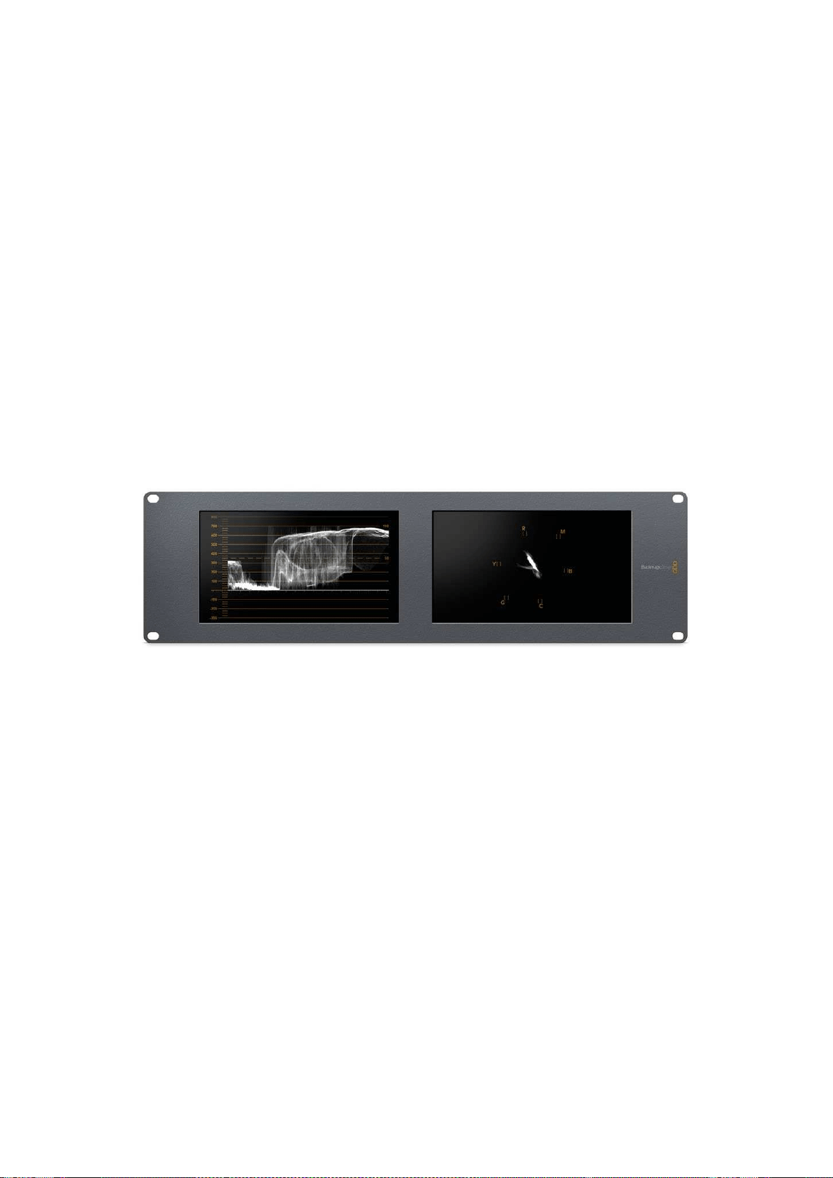
Usar SmartScope Duo 4K
O que é Blackmagic SmartScope?
Antigamente, os escopos de pós-produção e televisão de qualidade broadcast eram soluções
extremamente caras que permitiam apenas a visualização de um escopo de cada vez em uma tela
superpequena! Alem disso, alguns escopos são feios e não passam uma boa impressão para
ocliente.
Com o SmartScope Duo 4K, você obtém monitores de forma de onda que permitem que você
acompanhe qualquer aspecto do seu sinal de vídeo em monitores duplos em tempo real. Todos os
ajustes feitos no sinal de entrada no Blackmagic SmartView Setup podem ser vistos imediatamente
no SmartScope Duo 4K! E mais, cada sinal de entrada pode ser enviado para qualquer um dos
monitores via a saída SDI loop, ou seja, você pode usar o monitor da direita para exibir o escopo do
sinal indo para o monitor da esquerda.
Os escopos exibidos pelo SmartScope Duo 4K são selecionados no software Blackmagic
SmartView Setup. Selecione seus escopos a partir do menu suspenso “Display”.
A informação abaixo e nas próximas páginas explica como cada exibição de escopo é aplicada para
que você obtenha um entendimento melhor sobre cada uma das suas funções.
É fácil configurar seu Blackmagic SmartScope Duo 4K para exibir um escopo
diferente em cada monitor usando o Blackmagic SmartView Setup.
Display para Monitoramento de Vídeo
O display “Video Monitoring” oferece um monitoramento confiável e útil para que você possa
visualizar o vídeo que está sendo recebido pelo SmartScope.
Se seu sinal de entrada for SD, você pode optar por exibi-lo em tarjas laterais 4:3 ou 16:9 através do
menu suspenso “Set”. Quaisquer alterações feitas nas configurações de brilho, contraste ou
saturação da tela LCD podem ser imediatamente visualizadas neste modo. Observe que a alteração
dessas configurações afeta apenas o monitor e não o sinal de vídeo, assim os escopos não serão
impactados por essas mudanças de saturação ou brilho.
357Usar SmartScope Duo 4K

É útil configurar um monitor como “Video Monitoring” e o outro para a visualização de seu escopo.
Para fazer isto, use um cabo curto para conectar a saída loop SDI do “Monitor 1” à entrada SDI do
“Monitor 2”.
Você pode visualizar vídeos SD em tarjas laterais 4:3
ou em widescreen 16:9 selecionando as opções do
menu “Set” no Blackmagic SmartView Setup. Configure
“SD Aspect to 16:9” quando estiver visualizando vídeos
em definição padrão no formato anamórfico.
A configuração do display para monitoramento de vídeo exibe o sinal de vídeo
daforma como ele geramente aparece na tela do televisor ou monitor.
Display em Forma de Onda
O display “Waveform” fornece uma forma de onda codificada digitalmente de modo semelhante aos
monitores de forma de onda de luminância tradicional, usado para monitorar e ajustar os níveis de
luminância (brilho) do seu sinal de vídeo.
Os monitores de forma de onda de luminância tradicional são compatíveis apenas com vídeos de
definição padrão no formato composto analógico. No entanto, a visualização em forma de onda do
SmartScope Duo 4K funciona em Ultra HD e HD assim como SD, assim você pode ajustar ajustar os
níveis de luminância de forma consistente e fácil mesmo ao monitorar formatos de vídeo digital em
alta definição!
Selecione a forma de onda a partir do menu suspenso “Display” no Blackmagic SmartView Setup.
Você deve certificar-se de que os pretos na sua forma de onda não atinjam 0% e os brancos não
ultrapassem 100%, pois isso significa que você está obtendo valores de luminância ilegais.
O monitoramento em forma de onda é uma representação gráfica da imagem, que mostra valores
de luminância na mesma posição em relação àqueles dentro do quadro. Por exemplo, se parte do
céu estiver superexposta, você a verá na mesma posição horizontal no display em forma de onda
que ela aparece no quadro.
Dependendo da sua imagem, sua forma de onda terá uma aparência diferente. Se estiver
monitorando vídeos de alto contraste, pode ser que não veja valor algum nos tons de cinza.
Aimagem abaixo apresenta uma forma de onda de uma imagem exposta uniformemente com um
patch escuro à esquerda e valores mais luminosos do centro do quadro para a direita.
358Usar SmartScope Duo 4K

Display em forma de onda exibindo valores de luminância.
Selecione “Waveform” nas configurações “Display” do Blackmagic SmartView
Setup para visualizar os valores de luminância no seu sinal de vídeo.
Display em Vetorscópio
O display “Vectorscope” exibe as cores em um sinal de vídeo. Dependendo do padrão dos sinais de
teste de barras de cor usado na sua instalação, selecione 100% ou 75% no menu suspenso “Set” no
Blackmagic SmartView Setup.
Algumas pessoas acreditam que o vetorscópio pode ser usado para verificar níveis ilegais, mas isso
não é correto. O display no padrão RGB é que deve ser usado para a verificação de cores ilegais.
Omotivo pelo qual você não pode usar um vetorscópio para tal verificação é que ambos os valores
de crominância e luminância são necessários. Por exemplo, as cores próximas dos pontos brancos
ou pretos no vídeo não podem ser saturadas como as cores muito mais escuras, que podem ser
usadas nos tons de cinza. Como o display em vetorscópio exibe somente cores, e não valores de
luminância, ele não pode ser usado exclusivamente para verificar cores ilegais.
O display em vetorscópio é a melhor ferramenta para verificar níveis de cores de fitas de vídeo
analógicas antigas, onde você precisa ajustar níveis cromáticos. Basta reproduzir o segmento da
barra de cores da fita de vídeo e, depois, ajustar as configurações cromáticas e de matiz para definir
as cores do vídeo nas caixas quadradas na gratícula.
359Usar SmartScope Duo 4K
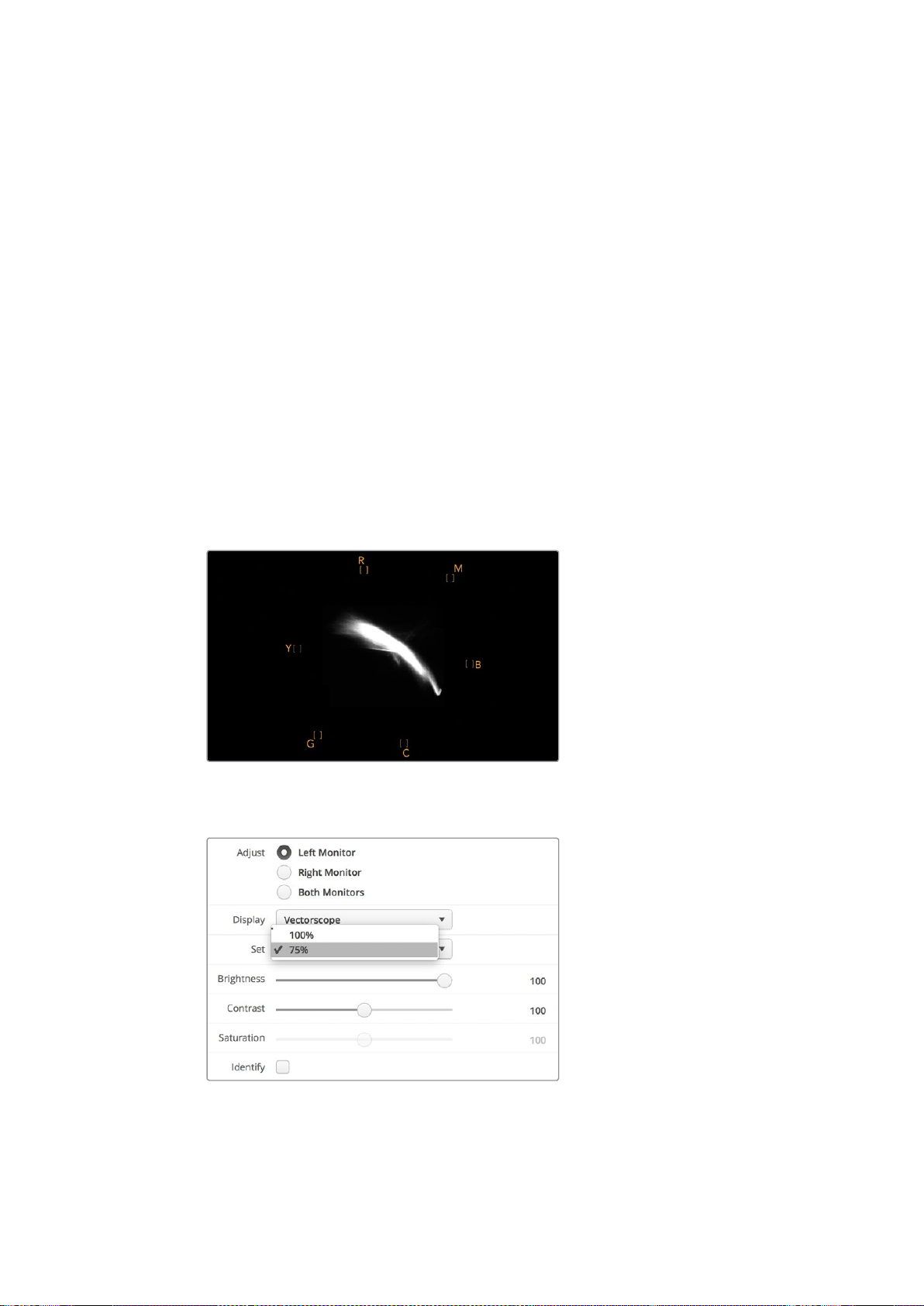
O display em vetorscópio também é perfeito para gradação de cor, já que você pode facilmente ver
se seu vídeo recebeu balanço de branco corretamente ou se há um tom de cor. Se seu vídeo
possuir um tom de cor, o display desviará para o centro e você provavelmente verá dois pontos
centrais. Geralmente, o apagamento no sinal de vídeo cria um ponto no centro do vetorscópio e isso
acontece porque o apagamento no vídeo é preto sem qualquer cor. O apagamento fornece um
ponto de referência útil para ajudar a reconhecer áreas do vídeo preto sem qualquer
informação de cor.
Se seu vídeo tiver um tom de cor, você poderá visualizar os pretos se afastando da cor e do centro.
Ograu de deslocamento representa a quantidade do tom de cor no seu vídeo e é possível ver
oafastamento nos detalhes pretos e brancos do seu vídeo. Isto faz com que o display em
vetorscópio seja valioso na remoção do tom de cor e na recuperação do balanço de branco correto.
Este tipo de display permite que você trabalhe com cores no seu vídeo dentro dos limites, sem
adicionar acidentalmente tons indesejados aos pretos e brancos. O balanço de cor branca pode ser
monitorado tanto no display em padrões RGB quanto no display em vetorscópio. Os problemas com
balanço de cor serão geralmente mais fáceis de visualizar no display em vetorscópio.
Ao fazer a correção de cor de imagens com tons de pele, especialmente rostos, você deve manter
asaturação da cor quente ao longo de uma linha aproximadamente na posição de 10 horas no
vetorscópio. Isto é conhecido como “flesh tone line” e é baseado na cor do sangue sob a superfície
da pele. A “flesh tone line” é, portanto, aplicável a todos as pigmentações de pele e é a melhor
maneira de garantir que os tons de pele do seu talento fiquem naturais.
Display em vetorscópio exibindo “flesh tone
line” em direção à posição de 10 horas.
Configure seu vertorscópio como sinais de teste de barras de cor a 100% ou 75%.
360Usar SmartScope Duo 4K
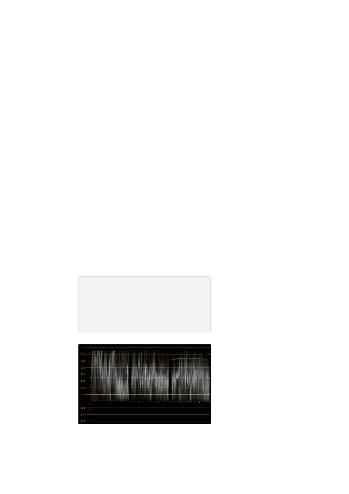
Display em Padrões
Os displays “RGB Parade” e “YUV Parade” são ideais para correção de cor, verificação de cores
ilegais e verificação de níveis.
Ao fazer a correção de cor, selecione “RGB Parade” no menu suspenso “Display” no Blackmagic
SmartView Setup. A visualização no padrão RGB exibe a altura máxima dos canais individuais de cor
vermelho, verde e azul. O monitoramento dos níveis de cada canal simplifica a correção de cor
etambém é fácil visualizar o balanço de cor nos pretos, meios-tons e brancos do sinal de vídeo.
Odisplay no padrão RGB possibilita que você identifique os detalhes comuns aos canais vermelho,
verde e azul, simplificando o balanço de cor e a remoção de tons de cor indesejados.
Ao fazer a correção de cores, é importante certificar-se de que os níveis de vídeo estejam
completos, mas não cortados. Caso queira aumentar o nível de vídeo, certifique-se também de que
ele não ultrapasse o limite RGB ou você obterá níveis ilegais. Alguns equipamentos não permitem
ageração de níveis 100% RGB ilegais, porém outros equipamentos permitirão. O SmartScope Duo
4K deixa você visualizar os níveis ilegais sempre que eles ocorram.
Vídeos ilegais também podem ocorrer nos níveis de preto e branco. Em alguns sistemas de
correção de cor, os níveis de preto podem ser reduzidos para o ponto preto abaixo de 0%. Se você
notar níveis de preto ilegais, basta adicionar um pedestal, “Lift”, ou ganho para eliminá-los, mas
verifique o nível de gratícula a 100% para garantir que todo o sinal de vídeo não tenha sido elevado
e gerado cores ilegais nos brancos.
Para checar os níveis YUV, selecione “YUV Parade” no menu suspenso “Display”. Esta visualização
é útil porque os valores de luminância (brilho) são separados dos valores cromáticos (cor), o formato
dos sinais de vídeo para a teledifusão. A forma de onda da esquerda mostra as informações de
luminância e a segunda e terceira formas de onda exibem as informações cromáticas. A visualização
no padrão YUV é útil para a calibração dos valores cromáticos dos sinais de vídeo para um padrão
de teste de barra de cores, assim as cores são representadas fielmente e o sinal sendo transmitido
é exibido pelos televisores.
A correção de cor é um processo de ajuste constante que ajuda a alcançar as melhores
imagens sem gerar níveis ilegais!
Visualização no padrão RGB.
Terminologia de Correção de Cores
Pretos – Níveis de pretos no sinal de vídeo
Meios-Tons – Níveis de tons de cinza no sinal de vídeo
Brancos – Níveis de brancos no sinal de vídeo
361Usar SmartScope Duo 4K

Visualização no padrão YUV.
Selecione entre “RGB Parade” e “YUV Parade” no menu suspenso
“Display” no Blackmagic SmartView Setup.
Display em Histograma
O display “Histogram” é mais conhecido entre designers gráficos e operadores de câmera.
Eleexibe a distribuição de informações do branco para o preto e permite que você monitore de
perto o tanto que os detalhes são perdidos nos brancos e pretos do vídeo. O display em histograma
também permite visualizar os efeitos dos ajustes de gama no vídeo.
O vídeo preto é exibido na esquerda do display e os brancos na direita. Normalmente, todos os
vídeos devem estar entre intervalos de 0% e 100% do display em histograma. Eles são cortados
caso se encontrem abaixo de 0% ou acima de 100%. Filmar vídeos com perdas pode ser algo muito
ruim, já que os detalhes nos pretos e brancos precisam ser preservados caso você queira fazer
posteriormente a correção de cores em um ambiente controlado. Portanto, durante as filmagens,
mantenha o vídeo acima do corte preto e abaixo do corte branco para que tenha mais liberdade na
hora de ajustar as cores, sem que os brancos e pretos apareçam com menos contraste, saturação
edetalhes.
Durante a correção de cores, pode ser que você decida cortar seu vídeo e, nesse caso, o display
em histograma exibirá o efeito do corte e o tanto que está sendo cortado. Você pode até usar gama
para criar um look semelhante, com menos perda, ao mesmo tempo que mantém maisdetalhes.
Não é possível, porém, usar o display em histograma para verificar níveis ilegais, embora você
possa ver pretos e brancos ilegais. O display em histograma não exibe cores, mas ele pode
aparentar indicar níveis legais enquanto seu vídeo contém cores ilegais. Mais uma vez, o display no
padrão RGB oferece a melhor maneira de identificar níveis ilegais, já que ele os exibe em elementos
de cor e luminância do sinal de vídeo.
362Usar SmartScope Duo 4K

Configuração do display em histograma exibindo
distribuição dos brancos para os pretos.
Selecione “Histogram” no menu suspenso
“Display” no Blackmagic SmartView Setup.
Display com Medição de Áudio
O display com medição de áudio exibe os níveis de áudio embutidos do sinal de vídeo SDI. Até 16
canais de áudio embutidos são desembutidos e, depois, exibidos no formato dBVU ou dBFS.
O indicador VU, que mostra os níveis médios do sinal, é fácil de usar e muito comum em
equipamentos mais antigos. O VU é calibrado de acordo com a recomendação SMPTE de que um
tom de teste de 1 kHz seja configurado como -20 dBFS.
O dBFS é, essencialmente, um medidor do sinal de áudio digital como um todo e é comum em
equipamentos digitais modernos.
O escopo de áudio da direita é capaz de monitorar dois canais de áudio, os quais podem ser
selecionados no menu suspenso “Set”, como os canais 1 & 2, 3 & 4, etc. O escopo de áudio
apresenta o áudio em uma visualização X-Y, assim você pode monitorar problemas no balanço de
áudio, condições defasadas e se uma trilha de áudio é mono ou estéreo. O áudio mono deve
aparecer como uma única linha vertical em fase, “In Phase”. Se a linha estiver horizontal, significa
que seu áudio está fora de fase, “Out of Phase”, e poderia aplicar compensação (ex: perda de áudio)
quando recebido por equipamentos downstream. A fase do áudio, “Audio Phase”, é uma das avarias
de áudio mais comuns em instalações grandes, onde os cabos podem ser conectados
inadequadamente.
363Usar SmartScope Duo 4K

Ao monitorar sinais estéreos, a linha do escopo de áudio no lado direito se espalha para representar
a diferença entre os canais de áudio esquerdo e direito. Quanto mais som estéreo na trilha de áudio,
mais circular a linha aparecerá. Se o áudio tiver conteúdo estéreo mínimo, o estéreo aparecerá mais
concentrado por volta do eixo vertical.
Áudios de diálogo tendem a aparecer como uma linha vertical, enquanto músicas com muito
conteúdo estéreo farão com que o escopo seja exalado. Isso ocorre porque o áudio mono é L+R e
éexibido no eixo vertical, enquanto o conteúdo estéreo é L-R e é exibido no eixo horizontal para
mostrar a diferença do estéreo.
Display com medição de áudio mostrando os níveis de pico e o balanço de áudio.
Use o menu suspenso “Set” para selecionar o
par de canais de áudio a ser monitorado.
Conectar a uma Rede
Ao conectar um monitor SmartView ou SmartScope a uma rede, você pode ajustar as configurações
do monitor de múltiplas unidades remotamente.
Apesar dos monitores SmartView e SmartScope exibirem vídeos sem a necessidade de qualquer
configuração, os ajustes podem ser feitos antes da sua implementação. A configuração de rede
pode ser realizada somente com o uso direto de uma conexão USB a um computador.
364Conectar a uma Rede
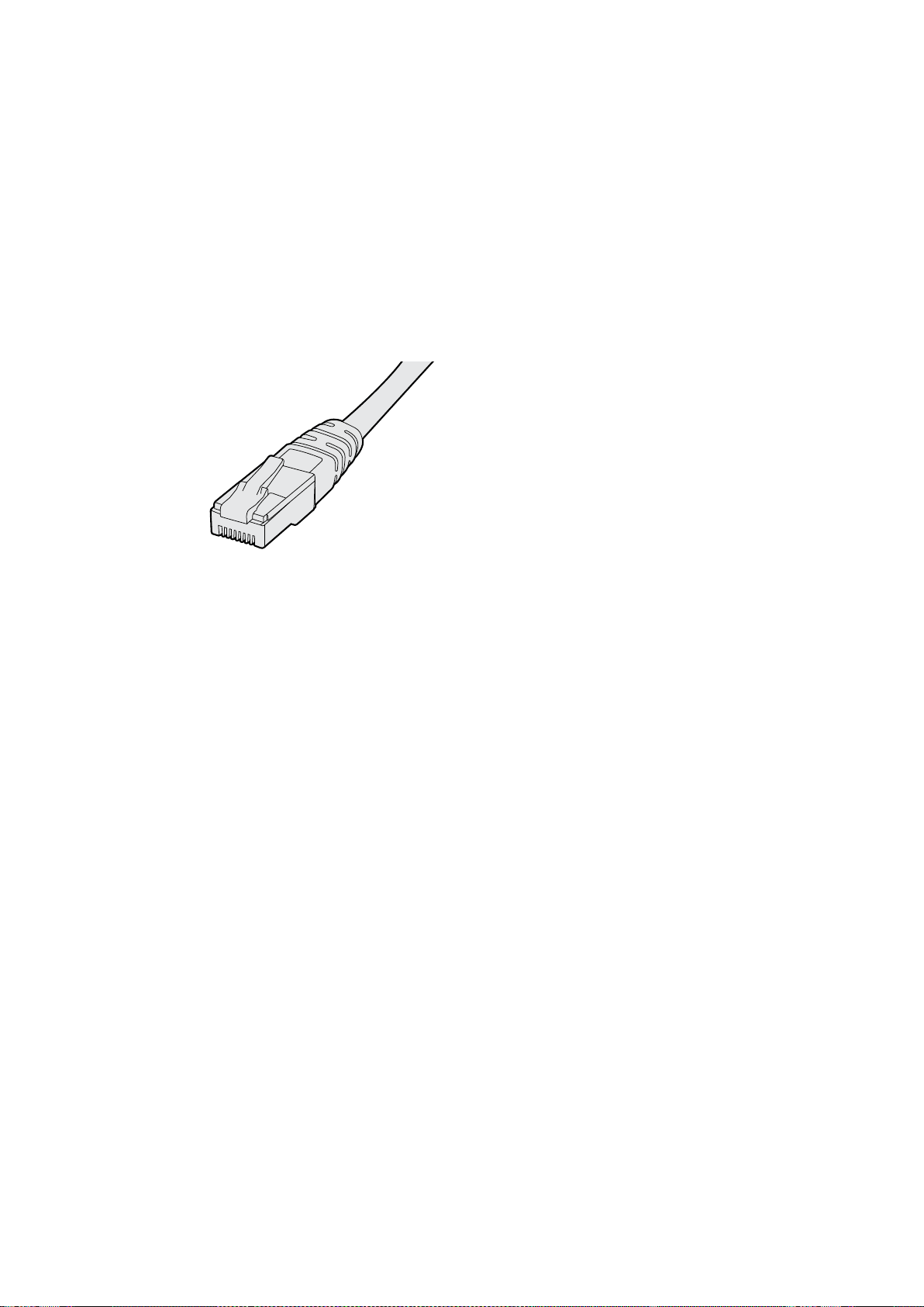
Ethernet Direta
A configuração remota de um monitor pode ocorrer através de uma conexão Ethernet direta ao seu
computador. Nenhum switch de rede é necessário nesta configuração, o que é excelente caso
precise fazer a instalação e configuração rapidamente. As unidades adicionais podem ser montadas
em cascata usando a porta de saída Ethernet com loop-through ativa em cada unidade.
Aalimentação deve ser fornecida a todas as unidades montadas em cascata.
Caso queira conectar várias unidades sem usar os endereços IP da rede atual do seu estúdio, ou
caso não tenha uma rede existente, basta conectá-las diretamente à porta Ethernet do seu
computador. Esta também é uma maneira rápida de conectar as unidades SmartView e SmartScope
via Ethernet, já que não precisa levar os cabos de volta a um switch de rede.
Conector Ethernet.
Switch de Rede Ethernet
Caso queira conectar várias unidades à rede do seu estúdio você precisará conectar somente um
SmartView ou SmartScope ao switch de rede, enquanto o resto pode ser montado em cascata
usando a porta de saída Ethernet com loop-through ativa em cada unidade para que apenas uma
única porta no seu switch seja usada. Assim, você não precisará levar múltiplos cabos de volta a um
switch de rede. A alimentação deve ser fornecida a todas as unidades para que a montagem em
cascata funcione.
A conexão a um switch de rede permite que qualquer computador na rede altere as configurações
de uma unidade. Qualquer computador laptop Mac ou Windows também é capaz de alterar as
configurações através de uma conexão WiFi, se sua rede incluir um ponto de acesso sem fio.
Será necessário seguir os passos abaixo para conectar o SmartView ou SmartScope a uma rede
baseada em IP de área local.
1 Conecte-se com segurança e ative a fonte de alimentação incluída na
sua unidade.
2 Conecte a unidade a um switch de rede, ou diretamente a um computador,
com um cabo Ethernet RJ45 padrão.
365Conectar a uma Rede
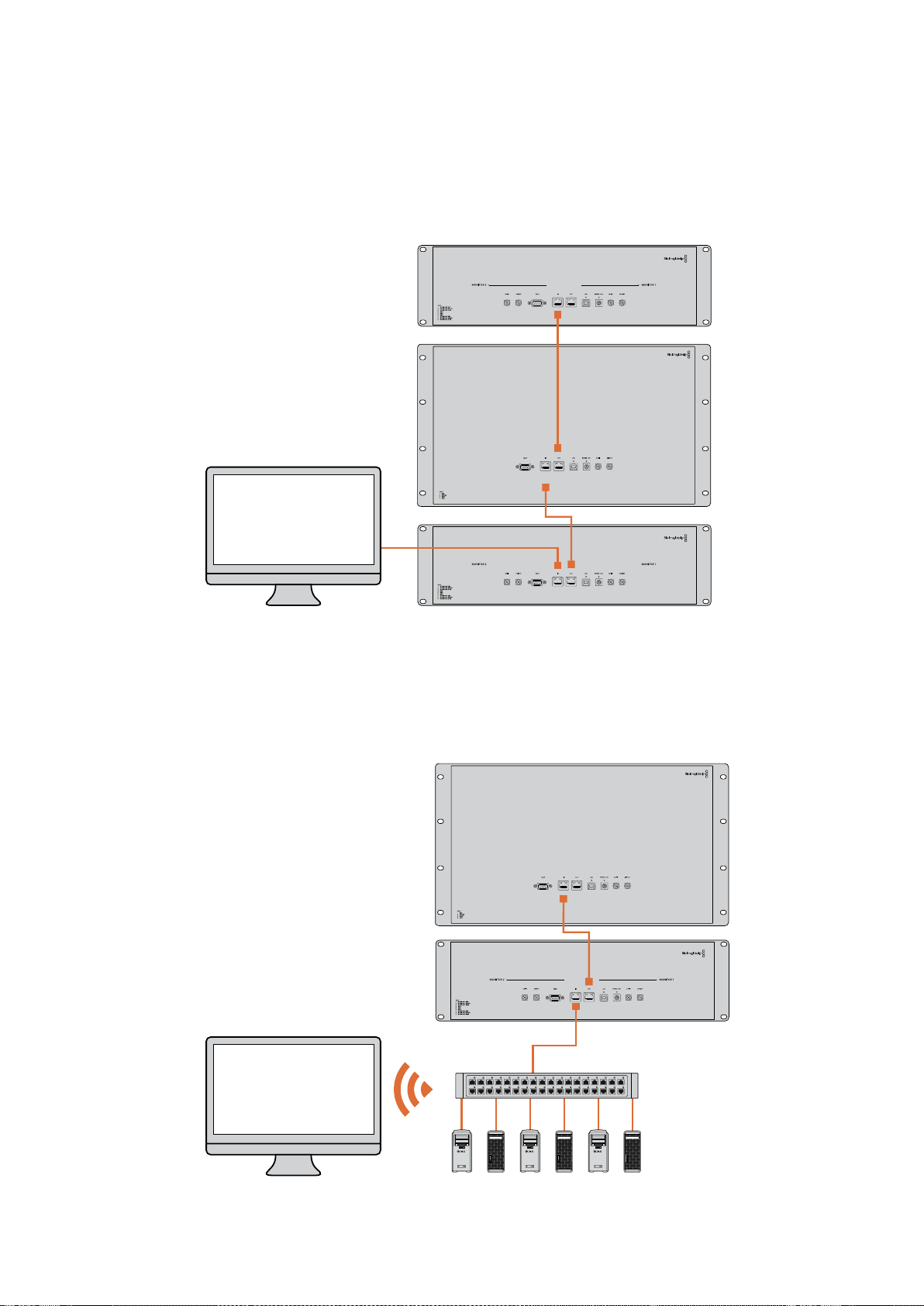
Diagrama de Conexão Ethernet Direta
Você pode conectar a porta Ethernet de um computador diretamente a uma unidade sem precisar
de um switch de rede. As unidades adicionais podem ser montadas em cascata para que você não
precise levar múltiplos cabos de volta a um switch de rede. A alimentação deve ser fornecida
atodas as unidades.
Diagrama de Conexão de Switch de Rede Ethernet
Caso deseje conectar várias unidades à rede atual do seu estúdio, precisará conectar apenas uma
unidade ao switch de rede. O resto pode ser montado em cascata para que você não precise levar
múltiplos cabos de volta a um switch de rede. A alimentação deve ser fornecida a todas
asunidades.
SmartScope 4KDuo
SmartScope 4KDuo
Switch de Rede
Ethernet
Computadores
Cliente
366Conectar a uma Rede

Ajustar Configurações de Rede
Configurações de Rede
Nome do Dispositivo
É recomendável alterar o nome do seu monitor para que cada unidade SmartView ou SmartScope
seja identificada facilmente na rede, por exemplo “Câmeras de Campo 1 & 2”, “Saída de
Multivisualização”, “Alimentações 4K” e etc.
Para mudar o nome do seu monitor, certifique-se de que ele esteja conectado via Ethernet ou USB.
Inicie o Blackmagic SmartView Setup e clique no ícone de configuração abaixo do nome do seu
monitor. Na página de configuração, clique em “Network” e edite o seu monitor localizado na seção
“Details”. Se o software detectar um nome inválido, um ícone de aviso aparecerá próximo a ele à
medida que você digita. Se o nome for válido, aparecerá um tique verde. Pressione a tecla “Return”
no teclado do seu computador para confirmar a alteração do nome.
Configurações de Rede
Para fazer alterações na seção de configurações de rede no Blackmagic SmartView Setup,
énecessário que o seu monitor Blackmagic esteja conetado ao computador via USB.
Asconfigurações de rede não podem ser alteradas via Ethernet.
Por padrão, o SmartView e o SmartScope usam DHCP para obter um endereço IP da sua rede
automaticamente.
Na ausência de um servidor DHCP, pode ser que você queira habilitar o recurso “Internet Sharing”
do macOS ou o recurso “Internet Connection Sharing” (ICS) do Windows 8.1 ou Windows 10, para
fornecer endereços DHCP a quaisquer unidades diretamente fixadas. Isto evitará a necessidade de
atribuir endereços IP estáticos manualmente a cada unidade. Você pode usar este recurso para
fornecer endereços DHCP mesmo que seu computador não tenha uma conexão com a Internet.
Ocompartilhamento da Internet é detalhado na seção de ajuda, “Help”, das documentações do
macOS e Windows 8.1 e 10.
Se o DHCP não puder ser usado na sua configuração, opte por configurar o endereço usando
“Static IP”. Para evitar o surgimento de um conflito de IP na sua rede, por favor solicite um endereço
IP disponível ao seu administrador de sistema. Você precisará especificar um endereço IP único
para cada unidade SmartView e SmartScope, assim como uma máscara de sub-rede comum. Não
énecessário alterar o valor padrão no campo “Gateway” a menos que você pretenda conectar suas
unidades a um gateway de rede, como um roteador de Internet.
Caso nenhum monitor SmartView ou SmartScope seja localizado na rede, pode ser que as unidades
não tenham recebido endereços IP via DHCP e será necessário ajustar manualmente cada unidade
com configurações de rede adequadas.
1 Conecte um monitor Blackmagic SmartView ou SmartScope ao seu
computador via USB e inicie o Blackmagic SmartView Setup.
2 Seu monitor conectado será exibido automaticamente na página inicial do
SmartView Setup e apresentará um ícone USB próximo ao seu nome.
3 Ajuste as configurações de rede do seu monitor.
4 Repita esses passos para todas as outras unidades que não receberam um
endereço IP via DHCP.
367Ajustar Configurações de Rede
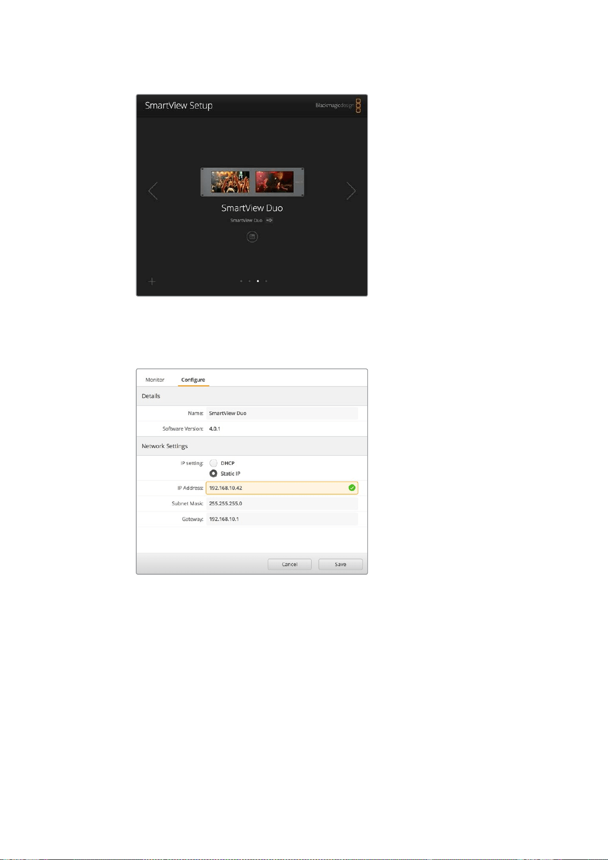
O ícone USB próximo ao nome do seu monitor mostra
que o monitor está conectado ao seu computador via
USB. Para fazer ajustes nas configurações de rede, seu
monitor Blackmagic precisa estar conectado via USB.
As configurações de rede podem ser ajustadas
para usar DHCP ou um enedereço IP estático e
podem ser alteradas apenas via USB.
Adicionar um Monitor Blackmagic
Se você já souber o endereço IP de um SmartView ou SmartScope Duo 4K, mas ele não aparecer
automaticamente na página inicial do Blackmagic SmartView Setup, é possível adicionar o monitor
manualmente. Para fazer isto:
1 Certifique-se de que o seu monitor Blackmagic esteja conectado via Ethernet.
Clique no ícone “+” no canto inferior esquerdo para abrir a janela “Add a
Blackmagic Monitor”.
2 Digite o endereço IP do monitor e clique em “Add”.
3 O software verificará a presença da unidade e a adicionará aos monitores
Blackmagic incluídos na página inicial do SmartView Setup. Clique no ícone da
seta direita para visualizar seu monitor recém-adicionado.
368Ajustar Configurações de Rede
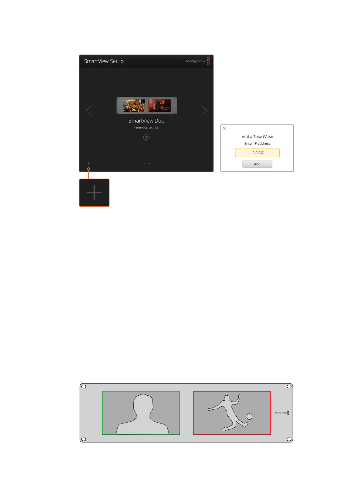
Você pode adicionar manualmente um monitor SmartView
ou SmartScope à lista dos monitores conectados clicando
no ícone “+” e inserindo o endereço IP do monitor.
Usar Sinalização
Conexões dos Pinos da Porta de Sinalização
A porta de sinalização do SmartView ou SmartView não precisa necessariamente estar conectada,
portanto você pode ignorar esta seção caso não pretenda usar o recurso de sinalização.
As telas do SmartView e SmartScope contam com bordas de sinalização independentes em
vermelho, verde ou azul, as quais podem ser usadas para indicar o status de um sinal de vídeo,
como no ar, pré-visualização ou gravação.
A porta de sinalização D-sub de 9 pinos aceita sinais de fechamento de contato dos switchers
esistemas de automação. Por favor consulte o diagrama de conexões dos pinos de sinalização para
informações sobre o cabeamento da porta de sinalização para uso com seu switcher ou sistema de
automação.
A descrição do cabeamento da porta D de 9 pinos está impressa na traseira da unidade, mostrando
os fechamentos de contato para exibir as bordas de sinalização vermelhas, verdes ou azuis em cada
monitor independente.
SmartView Duo exibindo bordas verdes e vermelhas.
369Usar Sinalização

Otimizar o Ângulo de Visualização
Se os monitores SmartView Duo, SmartView HD ou SmartScope forem instalados em um rack de
equipamentos muito alto, você deve inverter fisicamente as telas LCDs para obter o ângulo de
visualização ideal.
As imagens exibidas nos LCDs corresponderão automaticamente à orientação correta ao
detectarem a inversão. Uma chave de fenda pozidriv de número 02 é necessária para encaixar
edesencaixar o painel frontal da sua montagem traseira. Trata-se de um processo simples e não
involve a abertura da montagem traseira.
O processo a seguir descreve como inverter a unidade e ao mesmo tempo manter o logotipo da
Blackmagic Design na orientação correta no painel frontal. Uma chave de fenda pozidriv de número
02 é necessária.
1 Remova as chaves de fenda das laterais superior, inferior, esquerda e direita
do painel frontal. O SmartView Duo e o SmartScope Duo 4K possuem 10
parafusos e o SmartView HD possui 18 parafusos.
2 Retire o painel frontal da montagem traseira, conforme a ilustração.
3 Inverta a montagem traseira.
4 Reencaixe o painel frontal na montagem traseira invertida.
5 Reencaixe os parafusos no chassi.
O seu SmartView ou SmartScope agora está pronto para ser instalado em um rack alto.
Depoisde ser aparafusado no rack, o SmartView continuirá exibindo o ângulo de visualização
ideal mesmo após sofrer impactos, pois não há botões giratórios externos ou ajustes que levem
amanejos incorretos ou que fiquem frouxos.
SmartView Duo e SmartScope Duo 4K
Conexões dos Pinos de Sinalização
Pino Função
1 Monitor 1 Vermelho
2 Monitor 1 Verde
3 Monitor 1 Azul
4 Terra
5 Terra
6 Terra
7 Monitor 2 Vermelho
8 Monitor 2 Verde
9 Monitor 2 Azul
SmartView HD e SmartView 4K
Conexões dos Pinos de Sinalização
Pino Função
1 Vermelho
2 Verde
3 Azul
4 Terra
5 4 3 2 1
9 8 7 6
Porta de sinalização do SmartView
370
Otimizar o Ângulo de Visualização


Informações para Desenvolvedores
Devenvolver Software Personalizado com Hardware da Blackmagic Design
O Blackmagic SmartView Ethernet Protocol permite que os desenvolvedores controlem
remotamente hardware do Blackmagic SmartView e SmartScope com seus próprios programas
personalizados. O Blackmagic SmartView Ethernet Protocol é um protocolo de controle com status
baseado em texto.
Baixar o SmartView Ethernet Protocol
O Blackmagic SmartView Ethernet Protocol é gratuito. Ele está incluído neste manual SmartView &
SmartScope e está disponível para download em www.blackmagicdesign.com/br/support.
Juntar-se à Lista de Desenvolvedores da Blackmagic Design
A lista de emails de desenvolvedores da Blackmagic foi criada para discussões técnicas sobre as
tecnologias usadas pela Blackmagic Design, como QuickTime, Core Media, DirectShow, codecs,
APIs, SDKs e etc. Esta lista de emails é gratuita e funciona como um fórum onde os desenvolvedores
podem trocar ideias. Qualquer inscrito pode participar e os engenheiros da Blackmagic Design
também podem vir a participar, se necessário. Você pode se inscrever na lista de emails em
http://lists.blackmagicdesign.com/mailman/listinfo/bmd-developer.
Em alguns casos, solicitaremos uma breve descrição do software em desenvolvimento, caso o seu
nome de domínio não informe claramente que sua organização desenvolve software de vídeo.
Porfavor, não se sinta ofendido se isto acontecer, pois estamos apenas tentando evitar spams, vírus,
assim como clientes com perguntas não relacionadas a desenvolvedores e agências de emprego
ou vendedores tentando promover produtos na lista. Esta lista é voltada somente para
desenvolvedores.
Contactar o Suporte Técnico a Desenvolvedores da Blackmagic Design
Você também pode entrar em contato conosco via dev[email protected], caso tenha
dúvidas relevantes a desenvolvedores ou deseje fazer perguntas fora da lista.
Blackmagic 2K Format – Visão Geral
Os produtos Blackmagic Design são compatíveis com vídeos 3G-SDI, o que permite uma taxa de
dados duas vezes maior que a de vídeos HD-SDI tradicionais. Achamos que seria uma ótima ideia
adicionar suporte a filmes em 2K, via tecnologia 3G-SDI, para simplificar fluxos de trabalho de
longas-metragens. Com os sistemas de edição da Blackmagic Design alcançando popularidade no
mundo todo, agora milhares de pessoas podem se beneficiar da revolução no fluxo de trabalho de
longas-metragens.
372Informações para Desenvolvedores

Estas informações incluem tudo que os desenvolvedores de produtos precisam saber para a criação
de equipamentos SDI em 2K nativo. Obviamente, todos os produtos Blackmagic são atualizáveis,
portanto caso a indústria televisiva adote um padrão alternativo de filme baseado em SDI,
poderemos adicionar suporte a ele também!
Estrutura de Quadro
Transmitido a 23.98, 24 ou 25 quadros por segundo como um Progressive
Segmented Frame.
O vídeo ativo possui 2048 pixels de largura por 1556 linhas de profundidade.
Número total de linhas por quadro: 1650.
Número de palavras ativas por linha: 1535. Uma palavra consiste em uma amostra de 10 bits
para cada um dos quatro fluxos de dados, como um total de 40 bits. Consulte o diagrama
nomeado Blackmagic 2K Format - Formato do Fluxo de Dados.
Número total de linhas ativas: 1556.
Número de palavras por linha: 1875 para 23.98/24 Hz e 1800 para 25 Hz.
Campos por quadro: 2825 linhas cada.
As linhas ativas são localizadas nas linhas 16-793 (campo 1) e 841-1618 (campo 2).
Estrutura de Transporte
Baseado no mapeamento de enlace duplo SMPTE 372M e suporte SMPTE 425M-B para o
mapeamento SMPTE 372M em um enlace único a 3 Gb/s.
Sinais de referência de cronometragem, inserção de CRC e número de linha ocorrem
conforme mencionado acima.
Durante o vídeo ativo, dados vermelho, verde e azul de 10 bits são enviados na
sequência a seguir.
Dados ANC opcionais são inseridos em ambas interfaces virtuais.
No momento, somente os dados de áudio são incluídos: de acordo com a inserção de
áudio HD padrão (SMPTE S299M), os pacotes de dados de áudio são carregados no fluxo
de dados 2 e os pacotes de controle de áudio são carregados no fluxo de dado 1.
Fluxo de dado 1: Green_1, Green_2, Green_3, Green_5...Green_2047
Fluxo de dado 2: Blue_1, Blue_2, Green_4, Blue_5...Green_2048.
Fluxo de dado 3: Red_1, Blue_3, Blue_4, Red_5...Blue_2048.
Fluxo de dado 4: Red_2, Red_3, Red_4, Red_6...Red_2048.
Blackmagic 2K Format – Referência de Cronometragem Vertical
Este diagrama mostra os detalhes de cronometragem vertical com números de linha e campos, bits
vertical e horizontal para os códigos de sinal de referência de cronometragem.
Field 1 Active
F 1 0 0 0 0 0 0 0 0 0 0 0
V 1 1 1 1 1 1 0 0 0 0 1 1
LINE # 1650 1 2 ... 14 15 16 ... 792 793 ... 825
Field 2 Active
F 0 1 1 1 1 1 1 1 1 1 1 1
V 1 1 1 1 1 1 0 0 0 0 1 1
LINE # 825 826 827 ... 839 840 841 ... 1617 1618 ... 1650
373Informações para Desenvolvedores
Blackmagic 2K Format – Formato de Fluxo de Dados
Este diagrama mostra os formatos dos fluxos de dados próximos da seção de dados ANC opcionais
da linha horizontal. Observe que cada pixel ativo recebe até três amostras.
Fluxo de Dados
1
G2041
G2042
G2043
G2045
G2046
G2047
EAV(3FFh)
EAV(000h)
EAV(000h)
EAV(XYZh)
LN0
LN1
CRC0
CRC1
Dados de
Áudio/ANC
EAV(3FFh)
SAV(000h)
SAV(000h)
SAV(XYZh)
G1
G2
G3
G5
Fluxo de Dados
2
B2041
B2042
G2044
B2045
B2046
G2048
EAV(3FFh)
EAV(000h)
EAV(000h)
EAV(XYZh)
LN0
LN1
CRC0
CRC1
Dados de
Áudio/ANC
EAV(3FFh)
SAV(000h)
SAV(000h)
SAV(XYZh)
B1
B2
G4
B5
Fluxo de Dados
3
R2041
B2043
B2044
R2045
B2047
B2048
EAV(3FFh)
EAV(000h)
EAV(000h)
EAV(XYZh)
LN0
LN1
CRC0
CRC1
040
…
040
SAV(3FFh)
SAV(000h)
SAV(000h)
SAV(XYZh)
R1
B3
B4
R5
Fluxo de Dados
4
R2042
R2043
R2044
R2046
R2047
R2048
EAV(3FFh)
EAV(000h)
EAV(000h)
EAV(XYZh)
LN0
LN1
CRC0
CRC1
200
…
200
EAV(3FFh)
SAV(000h)
SAV(000h)
SAV(XYZh)
R2
R3
R4
R6
Palavra#
23.98/24 PsF
1870
1871
1872
1873
1874
1875
1
2
3
4
5
6
7
8
9
…
335
336
337
338
339
340
341
342
343
Palavra#
25 PsF
1795
1796
1797
1798
1799
1800
1
2
3
4
5
6
7
8
9
…
260
261
262
263
264
265
266
267
268
374Informações para Desenvolvedores

Blackmagic SmartView Ethernet Protocol v1.3
Resumo
O Blackmagic SmartView Ethernet Protocol é um protocolo de controle e status baseado em texto,
muito semelhante ao protocolo Videohub em termos de estrutura, acessado pela conexão com a
porta 9992 TCP em um dispositivo SmartView ou SmartScope.
Após conexão, o SmartView ou SmartScope envia um despejo completo do estado do dispositivo.
Depois do despejo inicial, as alterações do estado são enviadas de maneira assíncrona.
O dispositivo envia informações em blocos, os quais contêm um cabeçalho identificador, seguido
de dois-pontos. Um bloco pode abranger múltiplas linhas e é encerrado por uma linha em branco.
Para flexibilidade em relação às alterações futuras do protocolo, os clientes devem ignorar os
blocos que eles não reconhecem, até a linha em branco à direita. Nos blocos reconhecidos, os
clientes devem ignorar as linhas que eles não reconhecem.
A versão 1.3 do Blackmagic SmartView Ethernet
Protocol foi lançada com o software SmartView 1.3.
Preâmbulo do Protocolo
O primeiro bloco enviado pelo SmartView Server é sempre o preâmbulo do protocolo:
PROTOCOL PREAMBLE:
↵
Version 1.3
↵
↵
O campo da versão indica a versão do protocolo. Quando o protocolo é alterado de maneira
compatível, o número da versão de manutenção é atualizado. Se alterações incompatíveis são
feitas, o número da versão principal é atualizado.
Informações do Dispositivo
O bloco a seguir contém informações gerais sobre o dispositivo SmartView ou SmartScope
conectado.
SMARTVIEW DEVICE:
↵
Model: SmartView Duo
↵
Hostname: stagefront.studio.example.com
↵
Name: StageFront
↵
Mo nitor s: 2
↵
Inverted: false
↵
↵
Este exemplo exibe a saída para um dispositivo SmartView Duo, que possui duas telas LCDs.
O sinalizador INVERTED indica se o dispositivo detectou se ele foi inserido em uma configuração
invertida para otimizar o ângulo de visualização da tela LCD.
Legend
↵
carriage return
…
and so on
375Informações para Desenvolvedores

Configuração de Rede
O próximo bloco mostra a configuração de rede TCP/IP:
NETWORK:
↵
Dynamic IP: true
↵
Static address: 192.168.2.2
↵
St atic netm as k: 255.255.255.0
↵
St atic gatew ay: 192.168.2.1
↵
C u rr e nt ad d r e ss: 192.168.1.101
↵
C u rr e nt netm a sk: 255.255.255.0
↵
C u rr e nt g ate w ay: 192.168.1.1
↵
↵
As configurações de rede com o prefixo CURRENT mostram as configurações TCP/IP ativas, e elas
são somente leitura. As definições CURRENT refletem a configuração DHCP ou estática,
dependendo do sinalizador DYNAMIC IP.
Alterar Configurações de Rede
A rede pode ser configurada para usar uma configuração DHCP ou estática. Como habilitar DHCP:
NETWORK:
↵
Dynamic IP: true
↵
↵
Para configurar um endereço IP fixo, forneça todos os parâmetros estáticos:
NETWORK:
↵
Dynamic IP: false
↵
Static address: 192.168.2.2
↵
St atic netm as k: 255.255.255.0
↵
St atic gatew ay: 192.168.2.1
↵
↵
Os parâmetros com o prefixo CURRENT são somente leitura e mostram a configuração ativa,
independentemente da configuração ser estática ou dinâmica.
A alteração do nome do dispositivo, ou de quaisquer configurações de rede, gerarão a queda da
conexão IP. O dispositivo reiniciará sua rede e informará seu novo nome na rede.
Ajustar Configurações do Monitor
As configurações do display para cada monitor são especificadas individualmente. Um ou mais
monitores podem ser modificados ao mesmo tempo e múltiplas configurações podem ser
fornecidas em um bloco.
O intervalo válido para valores numéricos é 0-255. As propriedades CONTRAST e SATURATION
são centradas em zero, então o valor normal é 127, de forma que a imagem exibida é a mesma que a
original. Um valor maior que 127 em cada canal gerará um aumento no contraste ou na saturação e,
de maneira semelhante, um valor menor que 127 gerará uma redução.
Por exemplo, para configurar o brilho a 50% e para remover a saturação da imagem para Preto
& Branco:
MONITOR A:
↵
Brightness: 127
↵
Saturation: 0
↵
↵
376Informações para Desenvolvedores

Exibir SD em 16:9
O comando a seguir configura vídeos em definição padrão para exibição em 16:9:
MONITOR A:
↵
WidescreenSD: ON
↵
Exibir SD em 4:3
O comando a seguir configura vídeos em definição padrão para exibição em 4:3:
MONITOR A:
↵
WidescreenSD: OFF
↵
Configurações de Identificação e Sinalização
O sinalizador Identify é transitório e fará com que uma borda branca seja exibida ao redor de toda a
imagem por uma duração de 15 segundos, sendo restaurado depois. Este recurso tem como
objetivo principal a identificação do monitor que está sendo configurado no momento ao ser
montado em um rack com múltiplas unidades. Como habilitar:
MONITOR A:
↵
Ide ntify: tr u e
↵
↵
A borda IDENTIFY substituirá temporariamente quaisquer outras configurações de borda vigentes.
A propriedade BORDER pode ser usada para configurar de forma programática as bordas de
sinalização coloridas sem fio com uma das cores primárias: RED, GREEN, BLUE, WHITE ou NONE.
Esta configuração pode ser substituída pelos sinais de sinalização elétricos na entrada DB-9 do
próprio dispositivo. Por exemplo, para configurar a sinalização sem fio como verde:
MONITOR B:
↵
Border: green
↵
↵
A sinalização por fio sempre substituirá a sinalização sem fio. O relatório de estado completo
sempre indicará a atual borda válida.
Configurações do SmartScope
No SmartScope Duo 4K, cada monitor pode ser configurado para exibir um escopo diferente. Os
valores para ativar escopos específicos são mapeados como a seguir:
AudioDbfs
AudioDbvu
Histogram
ParadeRGB
ParadeYUV
Picture (o mesmo que Video Monitor)
Vector100
Vector75
WaveformLuma
MONITOR A:
↵
ScopeMode: Picture
↵
↵
No exemplo acima, Monitor A foi configurado como um monitor de vídeo.
377Informações para Desenvolvedores

Exibir SD em 16:9
Como configurar o modo Video Monitor para exibir vídeos em definição padrão em 16:9:
MONITOR A:
↵
ScopeMode: Picture
↵
WidescreenSD: ON
↵
Exibir SD em 4:3
Como configurar o modo Video Monitor para exibir vídeos em definição padrão em 4:3:
MONITOR A:
↵
ScopeMode: Picture
↵
WidescreenSD: OFF
↵
Ao configurar um dos monitores do SmartScope Duo 4K como medidores de áudio, é possível
também selecionar quais canais deseja exibir. Os valores para selecionar os canais de áudio são
mapeados da seguinte maneira:
0: Canais 1 e 2
1: Canais 3 e 4
2: Canais 5 e 6
3: Canais 7 e 8
4: Canais 9 e 10
5: Canais 11 e 12
6: Canais 13 e 14
7: Canais 15 e 16
MONITOR B:
↵
ScopeMode: AudioDbvu
↵
AudioChannel: 0
↵
↵
No exemplo acima, o Monitor B foi selecionado para exibir medidores de áudio em Dbvu com os
canais de áudio 1 e 2 selecionados para o medidor de fase.
Selecionar LUTs para o SmartView 4K
Como selecionar LUTs 3D usando SmartView 4K:
MONITOR A:
↵
LUT: 0LUT 1
1LUT 2
NONE DISABLE
↵
↵
378Informações para Desenvolvedores

Ajuda
Obter Ajuda
Há quatro maneiras de obter ajuda:
1 Acesse a Central de Suporte Técnico da Blackmagic Design em
www.blackmagicdesign.com/br/support para as informações de suporte
mais recentes.
2 Ligue para o seu revendedor da Blackmagic Design.
3 Seu revendedor local terá as últimas atualizações técnicas da
Blackmagic Design e poderá fornecer assistência imediata. Também
recomendamos que você verifique as opções de suporte oferecidas pelo
revendedor, pois ele pode organizar diversos planos de suporte baseados nas
exigências do seu fluxo de trabalho.
4 Outra opção é nos enviar um email com suas dúvidas usando o botão “Enviar
email” em www.blackmagicdesign.com/br/support.
5 Ligue para um escritório de suporte da Blackmagic Design. Você pode
encontrar o escritório mais próximo clicando no botão “Encontre a sua equipe
de suporte local” na parte inferior da página de suporte.
Por favor nos forneça o máximo de informação possível sobre seu problema técnico
eespecificações do sistema para que possamos encontrar uma resposta para o seu problema
oquanto antes.
379Ajuda

Informações Regulatórias e de Segurança
Informações Regulatórias
Eliminação de resíduos de equipamentos elétricos e eletrônicos dentro da União Europeia.
O símbolo no produto indica que este equipamento não pode ser eliminado com outros
materiais residuais. Para descartar seus resíduos de equipamento, ele deve ser entregue a
um ponto de coleta designado para reciclagem. A coleta separada e a reciclagem dos
seus resíduos de equipamento no momento da eliminação ajudarão a conservar os
recursos naturais e a garantir que sejam reciclados de uma maneira que proteja a saúde
humana e o meio ambiente. Para mais informações sobre onde você pode eliminar os
resíduos do seu equipamento para reciclagem, por favor contacte a agência de reciclagem
local da sua cidade ou o revendedor do produto adquirido.
Este equipamento foi testado e respeita os limites para um dispositivo digital Classe A,
conforme a Parte 15 das normas da FCC. Esses limites foram criados para fornecer
proteção razoável contra interferências nocivas quando o equipamento é operado em um
ambiente comercial. Este equipamento gera, utiliza e pode irradiar energia de
radiofrequência e, se não for instalado ou usado de acordo com as instruções, poderá
causar interferências nocivas nas comunicações via rádio. A operação deste produto em
uma área residencial pode causar interferência nociva, nesse caso o usuário será
solicitado a corrigir a interferência às suas próprias custas.
A operação está sujeita às duas condições a seguir:
1 Este dispositivo não poderá causar interferência nociva.
2 Este dispositivo deve aceitar qualquer interferência recebida, incluindo interferência que
possa causar uma operação indesejada.
Informações de Segurança
Este equipamento deve ser conectado a uma tomada com uma conexão aterrada
protegida.
Para reduzir o risco de choque elétrico, não exponha este equipamento a gotejamento ou
respingos.
Este equipamento é adequado para uso em locais tropicais com uma temperatura
ambiente de até 40ºC.
Certifique-se de que ventilação adequada seja fornecida ao redor do produto e não
estejarestrita.
Ao montar o produto em rack, certifique-se de que a ventilação não esteja restringida por
equipamentos adjacentes.
Não há componentes em seu interior reparáveis pelo operador. Solicite o serviço de
manutenção à assistência técnica local da Blackmagic Design.
Use apenas em altitudes inferiores a 2000 m acima do nível do mar.
Este produto tem os recursos de conexão para módulos transceptores de fibra óptica com
fator de forma SFP. Use apenas módulos SFP ópticos de Laser de classe 1.
Módulos SFP recomendados pela Blackmagic Design:
3G-SDI: PL-4F20-311C
6G-SDI; PL-8F10-311C
380Informações Regulatórias e de Segurança

Aviso para Pessoal de Assistência Autorizado
Desconecte a alimentação de ambas as entradas de alimentação antes de efetuar
operações de assistência!
Cuidado – Interruptor Bipolar/ Aterramento Neutro
A fonte de alimentação neste equipamento possui um fusível tanto nos condutores
de linha quanto neutro e é adequada para conexão com o sistema de distribuição
de alimentação IT na Noruega.
Garantia
12 Meses de Garantia Limitada
A Blackmagic Design garante que este produto estará isento de quaisquer defeitos de materiais
efabricação por um período de 12 meses a partir da data de compra. Se o produto revelar-se defeituoso
durante este período de garantia, a Blackmagic Design, a seu critério, consertará o produto defeituoso
sem cobrança pelos componentes e mão-de-obra, ou fornecerá a substituição em troca pelo produto
defeituoso.
Para obter o serviço sob esta garantia você, o Consumidor, deve notificar a Blackmagic Design do
defeito antes da expiração do período de garantia e tomar as providências necessárias para o
desempenho do serviço. O Consumidor é responsável pelo empacotamento e envio do produto
defeituoso para um centro de assistência designado pela Blackmagic Design com os custos de envio
pré-pagos. O Consumidor é responsável pelo pagamento de todos os custos de envio, seguro, taxas,
impostos e quaisquer outros custos para os produtos que forem devolvidos por qualquer razão.
Esta garantia não aplica-se a defeitos, falhas ou danos causados por uso inadequado ou manutenção
ecuidado inadequado ou impróprio. A Blackmagic Design não é obrigada a fornecer serviços sob esta
garantia: a) para consertar danos causados por tentativas de instalar, consertar ou fornecer assistência
técnica ao produto por pessoas que não sejam representantes da Blackmagic Design, b) para consertar
danos causados por uso ou conexão imprópria a equipamentos não compatíveis, c) para consertar
danos ou falhas causadas pelo uso de componentes ou materiais que não são da Blackmagic Design,
d) para fornecer assistência técnica de um produto que foi modificado ou integrado a outros produtos
quando o efeito de tal modificação ou integração aumenta o tempo ou a dificuldade da assistência
técnica do serviço. ESTA GARANTIA É FORNECIDA PELA BLACKMAGIC DESIGN NO LUGAR DE
QUAISQUER OUTRAS GARANTIAS, EXPLÍCITAS OU IMPLÍCITAS. A BLACKMAGIC DESIGN E SEUS
FORNECEDORES NEGAM QUAISQUER GARANTIAS IMPLÍCITAS DE COMERCIALIZAÇÃO OU
ADEQUAÇÃO A UMA FINALIDADE ESPECÍFICA. A RESPONSABILIDADE DA BLACKMAGIC DESIGN
DE CONSERTAR OU SUBSTITUIR PRODUTOS DEFEITUOSOS É A ÚNICA E EXCLUSIVA MEDIDA
FORNECIDA AO CONSUMIDOR PARA QUAISQUER DANOS INDIRETOS, ESPECIAIS OU ACIDENTAIS
INDEPENDENTEMENTE DA BLACKMAGIC DESIGN OU DO FORNECEDOR TIVER INFORMAÇÃO
PRÉVIA SOBRE A POSSIBILIDADE DE TAIS DANOS. A BLACKMAGIC DESIGN NÃO É RESPONSÁVEL
POR QUAISQUER USOS ILEGAIS DO EQUIPAMENTO PELO CONSUMIDOR. A BLACKMAGIC NÃO É
RESPONSÁVEL POR QUAISQUER DANOS CAUSADOS PELO USO DESTE PRODUTO. O USUÁRIO
DEVE OPERAR ESTE PRODUTO POR CONTA E RISCO PRÓPRIOS
© Direitos autorais 2018 Blackmagic Design. Todos os direitos reservados. ‘Blackmagic Design’, ‘DeckLink’, ‘HDLink’, ‘Workgroup
Videohub’, ‘Multibridge Pro’, ‘Multibridge Extreme’, ‘Intensity’ e ‘Leading the creative video revolution’ são marcas comerciais
registradas nos Estados Unidos e em outros países. Todos os outros nomes de empresas e produtos podem ser marcas comerciais
de suas respectivas empresas com as quais elas são associadas.
381Garantia


Hoş Geldiniz
Herkesin en yüksek kalitedeki videoya erişim sağlamasını mümkün kılarak, televizyon
endüstrisinin tam anlamıyla yaratıcı bir endüstri olmasına ilişkin hayalimizi paylaştığınızı umuyoruz.
Video izleme imkanı, bir tesisin her yerinde gereklidir. SmartView 4K bir native 4K LCD’ye sahip
olduğundan, Ultra HD videoyu tam çözünürlükte izleyebilirsiniz. Buna ek olarak, ayarları hızla
değiştirmenize olanak veren bir kontrol paneli ile şık 6RU kasaya sahiptir. SmartView HD bir
inçten daha az bir incelikte, inanılmaz 6RU rack kasada 17 inçlik bir LCD sunar. SmartView Duo;
bir inçten daha ince olan 3RU rack kasada, birbirinden tamamen bağımsız iki adet zarif 8 inç
LCD sunar. SmartScope Duo 4K, dalga şekli (waveform) skop işlevselliği olan, iki adet bağımsız
8 inç LCD içerdiğinden, video seviyelerinizi anında izleyebilirsiniz. Tüm SmartView monitörleri,
3G-SDI yoluyla SD, HD ve 2K videoyu destekler. SmartScope Duo 4K ve SmartView 4K;
sırasıyla 6G-SDI ve 12G-SDI aracılığıyla, Ultra HD 4K videoyu destekler.
Video izleme çözümlerimiz; kutudan çıktığı haliyle kullanılmaya hazır olarak tasarlanmıştır.
Blackmagic SmartView kurulum yazılımımız, kullanıcıya kolay ve sezgisel bir yapılandırma aracı sunar.
Bu kullanım kılavuzu, SmartView ve SmartScope ürünlerinizin kurulumu için ihtiyacınız olan tüm
bilgileri içerir. Ancak IP adresleri hakkında veya bilgisayar ağlarına ilişkin bilgi sahibi değilseniz,
bir teknik asistandan yardım istemenizde yarar vardır. SmartView ve SmartScope ürünlerinin
kurulumu kolaydır fakat, kurulumunu yaptıktan sonra ayarlamanız gerekebilecek bir kaç tane,
kısmen teknik olan seçenekler bulunmaktadır.
Kurulumu tamamlamanızın aşağı yukarı 5 dakika sürmesini bekliyoruz. Lütfen
www.blackmagicdesign.com/tr adresinden internet sitemizi ziyaret ederek, bu kılavuz ile
SmartView yazılımının en son güncellemelerini indirmek için destek sayfasını tıklayınız. Son
olarak, yeni güncellemeleri size duyurabilmemiz için, bilgisayarınıza yazılım güncellemeleri
indirirken, ünitenizi sitemize kaydetmenizi rica ediyoruz. Sürekli yeni özellikler ve geliştirmeler
için çaba içinde olduğumuzdan, yorumlarınızı almaktan mutluluk duyarız.
Grant Petty
CEO Blackmagic Design

İçindekiler
SmartView & SmartScope
Başlarken 385
SmartView ve SmartScope ile Tanışın 385
Video Kaynaklarının Takılması 386
Bilgisayarınızın Takılması 386
Blackmagic SmartView Setup Yazılımının Yüklenilmesi 387
Blackmagic SmartView Setup YazılımınınKullanımı 388
Yazılımın Güncellenmesi 388
Monitör Ayarlarının Değiştirilmesi 388
SmartView 4K’nın Kullanımı 391
Blackmagic SmartView 4K ile Tanışın 391
Kontrol Panel Butonları 392
Blackmagic SmartView Setup Kullanılarak
3D LUT’ların Yüklenmesi 394
SmartScope Duo 4K Kullanımı 395
Blackmagic SmartScope Nedir? 395
Video İzleme Ekranı 395
Waveform (Dalga Şekli) Ekranı 396
Vektörskop Ekranı 397
Parade Ekranı 399
Histogram Ekranı 400
Ses Göstergeleri Ekranı 401
Bir Ağa Bağlanırken 402
Doğrudan Ethernet Bağlantısı 403
Ethernet Ağ Anahtarı 403
Ağ Ayarlarının Değiştirilmesi 405
Ağ Ayarları 405
Bir Blackmagic Monitörünün İlave Edilmesi 406
Tally Özelliğinin Kullanılması 407
Tally Port Pin Bağlantıları 407
İzleme Açısının Optimize Edilmesi 408
Yazılım Geliştirici Bilgileri 410
Blackmagic 2K Formatı – Genel Tanıtım 410
Blackmagic 2K Format – Vertical Timing Reference (DikeyZamanlama Referansı) 411
Blackmagic 2K Format – Data Stream Format 412
Blackmagic SmartView Ethernet Protocol v1.3 413
Yardım 417
Düzenleyici Bildirim ve Güvenlik Bilgileri 418
Garanti 419
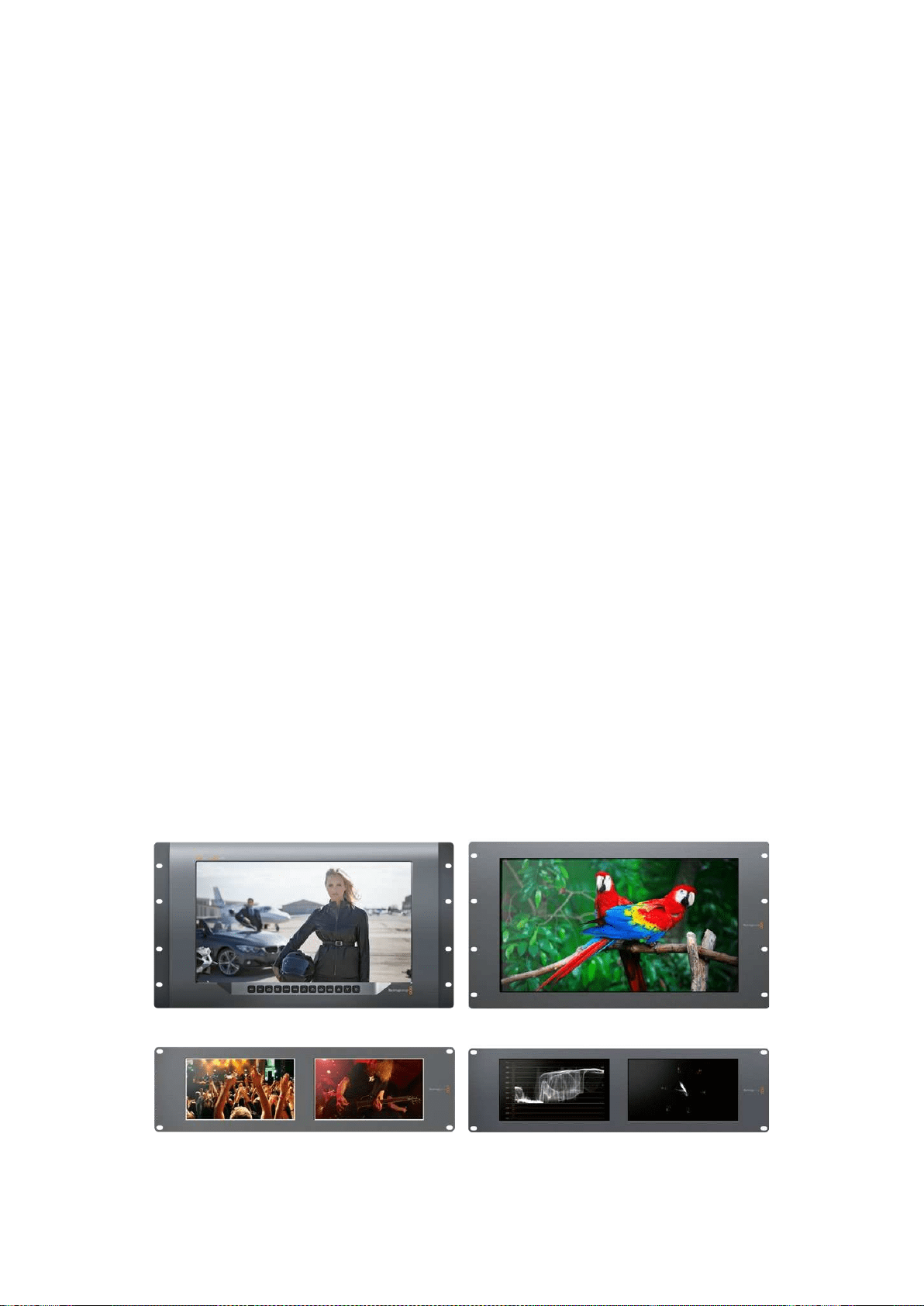
Başlarken
SmartView ve SmartScope ile Tanışın
SmartView monitörleri; rack bazlı izleme kurulumuna ihtiyacı olan her tesis için idealdir.
Kurulumunuzu yapıp ürünlerinizi kullanmaya başlamanız için yapmanız gereken tek şey, ürünleri
güç kaynağına takmak ve bir SDI kaynağını bağlamaktır.
SmartView 4K, 15.6 inç 4K LCD ekrana sahip olduğundan SD, HD veya Ultra HD videoyu native
3840x2160 piksel çözünürlükte izleyebilirsiniz. Ön kontrol panel butonları sayesinde; girişleri kolayca
seçebilir, ekran parlaklığını ayarlayabilir, mavi kanaldaki gürültü seviyesini gözden geçirebilir,
blanking (karartma) bilgilerini izleyebilir, 3D LUT uygulayabilir ve daha fazlasını yapabilirsiniz.
SmartView HD; güvenle tam çözünürlüklü HD izleme için mükemmel bir 17 inç HD LCD
ekrana sahiptir.
SmartView Duo farklı video sinyallerinin eşzamanlı sergilenmesi için iki monitöre sahiptir.
Örneğin, monitörün biri bir YUV 4:2:2 sinyal sergileyebilirken diğeri RGB 4:4:4 sinyal alır.
Monitörün biri NTSC gösterirken, diğeri PAL gösterebilir. Çok sayıda değişik kombinasyonlar
oluşturulabilir ve monitörlerin her birine tek bir SDI kablo bağlamak kadar kolaydır.
SmartScope Duo 4K; SmartView Duo ile aynı özelliklere sahip olmakla birlikte, gerçek zamanlı olarak
video ve ses seviyelerini izlemek üzere waveform, vektörskop ve başka popüler skopların
görüntülenmesi için de kullanılabilir. Buna ek olarak, Ultra HD 4K için tam desteğe sahip oluyorsunuz.
SmartView ve SmartScope monitörleri üzerindeki tüm SDI giriş bağlantıları, 2K video dahil SD,
HD veya 3G-SDI sinyallerinin otomatik tespitini destekler. SmartView 4K ayrıca; 12G-SDI
aracılığıyla ayrıca, 2160p60 gibi formatlar dahil, Ultra HD’yi de tespit eder. SmartScope Duo 4K;
6G-SDI aracılığıyla, Ultra HD 4K videonun otomatik tespit özelliğine sahiptir.
Tek bir bilgisayardan, birden fazla SmartView ve SmartScope üniteleri için ayarları uzaktan
değiştirmek istediğinizde, bunları Ethernet aracılığıyla birbirine bağlayabilirsiniz. Böylece,
ayarları her değiştirmek istediğinizde, bir bilgisayar ve USB kablosu ile her bir üniteye
koşturmak zorunda kalmazsınız.
Kullanmaya başlamak için yapmanız gerekenler bu kadar. SmartView ve SmartScope ürünlerini
bağlamak, Blackmagic SmartView kurulum yazılımında monitör ayarlarını yapılandırmak ve bir
ağa bağlanmak hakkında daha ayrıntılı bilgi için, kılavuzu okumaya devam edin.
SmartView 4K SmartView HD
SmartView Duo SmartScope Duo 4K
385Başlarken

Video Kaynaklarının Takılması
SmartView ve SmartScope monitörleri; switcher, kamera, video yakalama kartları, deck ve disk
kaydediciler dahil, SDI ekipmanlara bağlanmaya yarayan standart BNC konektörler içerir.
Bir Görüntünün Elde Edilmesi
Videonuzu görüntülemek kolaydır! Yapmanız gereken tek şey, üniteyi çalıştırmak ve video kaynağınızı
bir SDI girişine takmaktır. Çalıştırıldıktan ve bağlandıktan sonra, videonuz hemen görüntülenecektir.
SD, HD ve 2K sinyaller, SDI giriş ve döngü (loop through) çıkış bağlantıları tarafından otomatik
olarak algılanır. SmartView 4K ve SmartScope Duo 4K ayrıca Ultra HD 4K’yı da algılar.
Ünite tarafından herhangi bir video sinyali alınmadığında, arka lamba söner ve bir sonraki
geçerli sinyal alınıncaya kadar güçten tasarruf yapılır.
Monitörlerin Birbirine Seri Bağlanması
Her bir SmartView ve SmartScope monitörünün bağımsız bir SDI girişi ve loop through çıkışı
bulunduğundan, aynı giriş sinyalini görüntülemeleri için, birden fazla monitörü birbirine
zincirleme bağlayabilirsiniz:
1 1. üniteyi çalıştırın. SDI girişe bir video kaynağı bağlayın. Video anında görüntülenecektir.
2 2. üniteyi çalıştırın. 1. ünitenin loop çıkışından bir SDI kablosunu, 2. ünite üzerindeki bir
SDI girişe bağlayın.
Birbirine bağlayabileceğiniz ünite sayısında bir sınır yoktur.
SmartScope Duo 4K monitörünü kullanarak dalga şekli (waveform) izleme yapıyorsanız, her iki ekranın
aynı giriş sinyalini kullanmaları için 1. monitörün çıkışını 2. monitöre loop yapmanız gerekecektir.
Artık videonuzu görüntüleyebildiğiniz için, monitör ayarlarını değiştirebilir, veya Blackmagic
SmartView 4K üzerine 3D LUT yüklemek için de kullanabileceğiniz, Blackmagic SmartView
kurulum yazılımını kullanarak, SmartScope Duo 4K monitöründen skoplar seçebilirsiniz.
SmartView 4K SmartView HD
SmartView Duo SmartScope Duo 4K
Bilgisayarınızın Takılması
Bilgisayarınızı USB aracılığıyla bağlayarak ve Blackmagic SmartView kurulum yazılımını
yükleyerek, SmartView veya SmartScope monitör ayarlarını yapılandırın.
USB bağlantısı ayrıca, Blackmagic Design internet sitesinden indireceğiniz dahili yazılım
güncellemelerini uygulamak için de kullanılabilir. Yazılım güncellemeleri; yeni özellikler, yeni
donanım ile uyumluluk ve yeni formatlar için destek sağlayabilir. Blackmagic SmartView kurulum
yazılımı hem macOS hem de Windows bilgisayarlarında çalışır.
386Başlarken
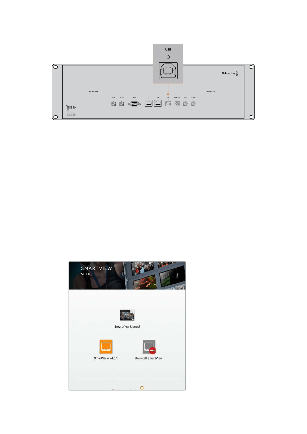
Blackmagic SmartView Setup Yazılımının Yüklenilmesi
Blackmagic SmartView kurulum yazılımı, macOS işletim sisteminin en son Sierra ve High Sierra
sürümlerinde, ve en son servis paketleri yüklü Windows 8.1 ve 10’un 64-bit versiyonlarında
çalışır. Arzu edilirse, Blackmagic SmartView kurulum yazılımı ağ üzerinde yüklü olan birden fazla
bilgisayara yüklenebilir.
Yazılım yükleyici SmartView ile birlikte gelen SD kartı üzerindedir, ancak
www.blackmagicdesign.com/tr/support adresine girmenizi ve en son sürüme sahip
olduğunuzdan emin olmanızı öneriyoruz.
macOS sistemine yüklemek için:
Kutuda gelen SD kartını veya indirilen disk görüntüsünü açın ve SmartView yükleme ikonu
üzerine çift tıklayın. Uygulamalar dosyasında; SmartView setup yazılımı, güncelleme yaparken
daha önceki sürümlerin silinmesi için bir program kaldırıcı ve bu kılavuz ile başka SmartView
bilgilerinin bulunduğu, bir belge dosyası içeren SmartView dosyası oluşturulacaktır.
Windows sistemine yüklemek için:
Windows sisteminde, kutuda gelen SD kartını veya indirilen zip dosyasını açın ve SmartView
yükleyici üzerine çift tıklayın. Yazılımı yüklemek için ekran üzerindeki komutları takip edin.
macOS sisteminde yüklemek için, kutuda gelen SD kartındaki veya
yüklenenler dosyasındaki SmartView.dmg dosyasını başlatın,
sonra SmartView yükleme ikonu üzerine çift tıklayın
387Başlarken
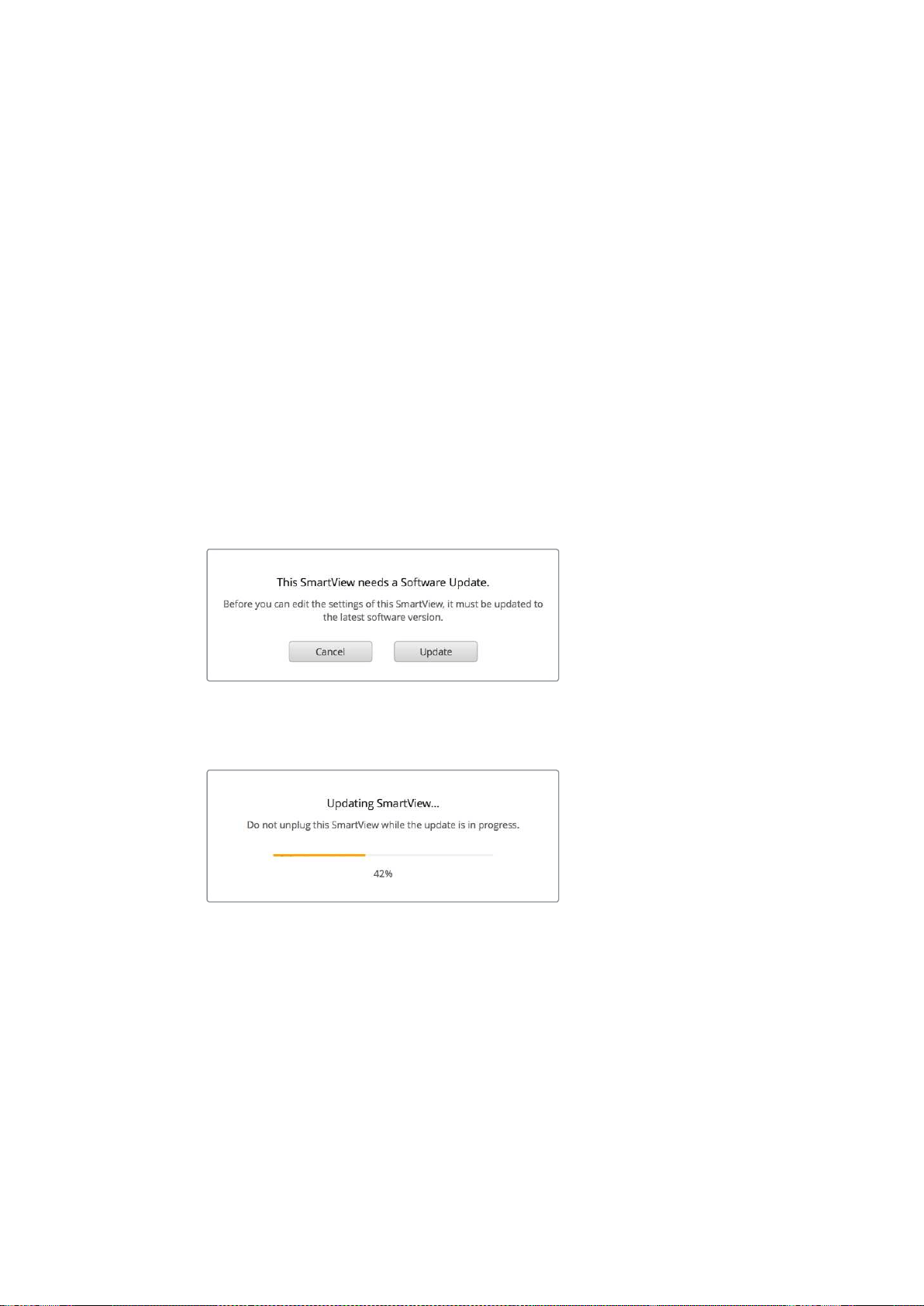
Blackmagic SmartView Setup
YazılımınınKullanımı
Yazılımın Güncellenmesi
Blackmagic SmartView kurulum yazılımı yüklenip başlatıldığında, monitör adının altındaki ayarlar
ikonunu tıklayın. SmartView veya SmartScope monitörünüzün dahili yazılımını güncellemeniz
için bir komut istemi belirebilir. Bu güncellemeyi yapmak için:
1 USB veya Ethernet aracılığıyla SmartView veya SmartScope monitörünüzü
bilgisayara bağlayın ve Blackmagic SmartView kurulum yazılımını başlatın.
2 Komut istemi belirince, ‘update’ (güncelle) üzerine tıklayın. Güncellemenin
tamamlanması 5 dakika kadar sürebilir.
3 Güncellemenin bitiminde şöyle bir mesaj belirir: “SmartView güncellenmiştir.”
4 ‘Close’ (Kapat) üzerine tıklayın.
Eğer herhangi bir dahili yazılım güncellemesi gerekmiyorsa, Blackmagic SmartView kurulum
yazılımı monitörünüzün ayarlar sayfasını açacaktır.
SmartView kurulum yazılımını başlatırken ve bağlı olan SmartView
veya SmartScope monitörünüzün ayarlar ikonunu açarken,
bir dahili yazılım güncellemesi gerekiyorsa bu mesaj belirir
Güncellemenin tamamlanması 5 dakika kadar sürer
Monitör Ayarlarının Değiştirilmesi
Başlatıldığında, Blackmagic SmartView kurulum yazılımı derhal, USB veya Ethernet aracılığıyla
bağlı bulunan SmartView ya da SmartScope ünitelerini arar ve bunları SmartView kurulum
anasayfasında görüntüler. Ağınıza bağlı bulunan birden fazla Blackmagic monitörü mevcutsa,
ayarlamak istediğiniz monitörü seçmek için, anasayfanın her iki tarafındaki sol ve sağ ok
ikonlarına tıklayın. Blackmagic monitörünüz bir USB ile bağlı ise, monitör adının yanında bir
USB ikonu belirecektir.
388Blackmagic SmartView Setup YazılımınınKullanımı
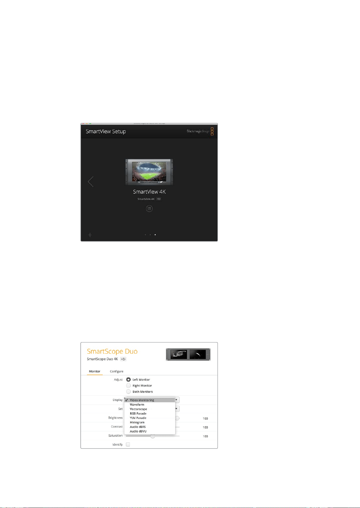
Ayarları değiştirmek için, Ethernet ve USB yoluyla bağlı olan monitörünüzü seçin ve monitör adı
altındaki ayarlar ikonuna tıklayın. Bu işlem, seçili olan monitörünüzün ayarlar sayfasını açacaktır.
Yaptığınız ayarlardan memnun kaldığınızda, bu ayarları kaydetmek ve SmartView kurulum
anasayfasına geri dönmek için ‘save’ (kaydet) butonuna tıklayın.
Blackmagic monitörleri için mevcut olan ayarlar ve bunları nasıl uygulayacağınız hakkında bilgi
için bir sonraki bölüme bakın. Blackmagic SmartView kurulum yazılımını kullanarak ağ ayarlarını
nasıl yapılandıracağınız hakkında bilgi için, “adjusting network settings” (ağ ayarlarının
değiştirilmesi) bölümüne bakın.
Blackmagic SmartView kurulum yazılımı, USB aracılığıyla veya bir
ağ üzerinden, yerel olarak bağlı bulunan SmartView ve SmartScope
ünitelerini otomatik olarak arar. Monitörünüzün dahili yazılımını
güncellerken, monitörünüzün USB veya Ethernet ile bağlı olduğundan
emin olun. Monitörünüzün adının yanında bir USB ikonu belirecektir.
Monitör Ayarları
Her bir monitör için, ayarları ve ekranları değiştirmek için, bunların Ethernet veya USB yoluyla
bağlı olması gerekmektedir. SmartView kurulum anasayfasındaki sol ve sağ ok ikonlarını
tıklayarak ayarlamak istediğiniz monitörü seçin, sonra monitör adının altındaki ayarlar ikonunu
tıklayın. Seçili bulunan Blackmagic monitörünüz tarafından desteklenen özelliklere uygun olarak
ayarlar sayfası otomatik olarak kişiselleştirilir.
SmartScope ile aşağı açılan ‘display’ (ekran) menüsünden skop
veya video izleme modu arasında seçim yapabilirsiniz.
389Blackmagic SmartView Setup YazılımınınKullanımı
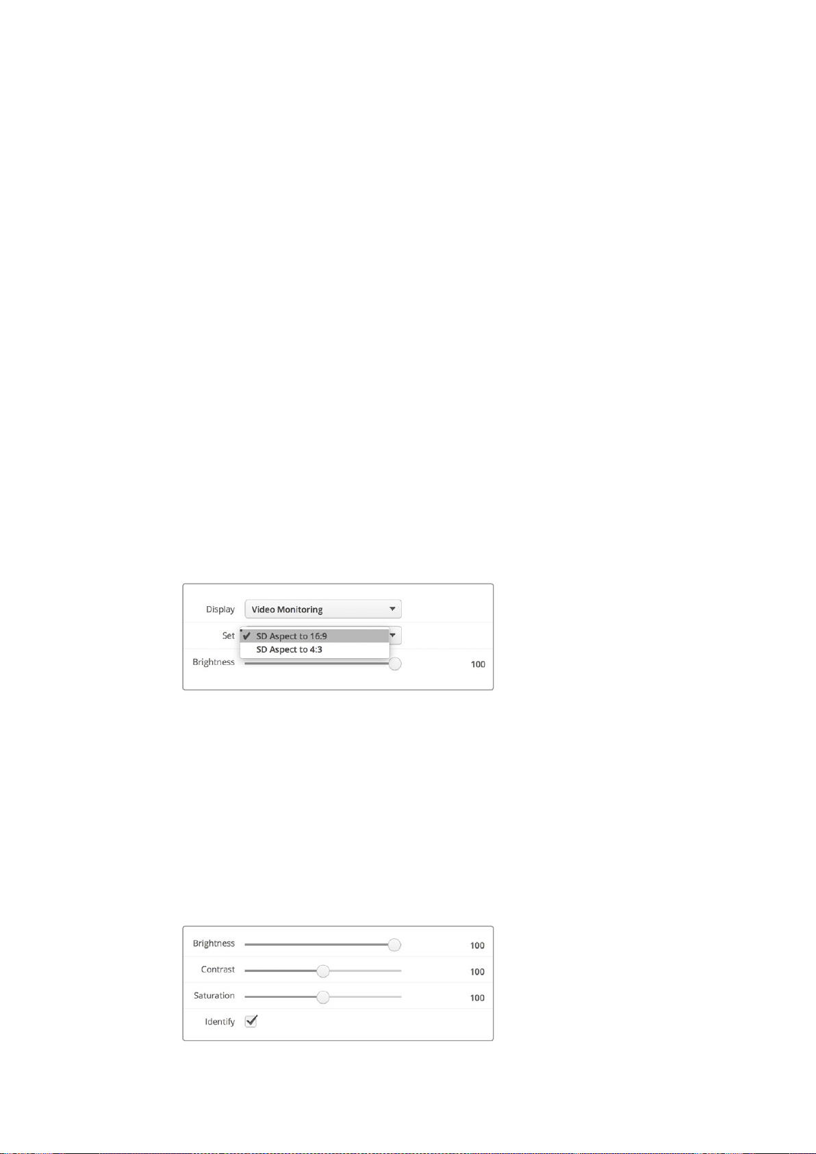
Ayarlama (Adjust)
Bir SmartScope veya SmartView Duo kullanırken, ‘left monitor’ (sol ekran), ‘right monitor’ (sağ
ekran) veya her ikisini aynı anda ayarlamak için ‘both monitors’ (her iki ekran) modları arasından
ayarlamak istediğiniz monitörü seçin. ‘Both monitors’ ayarı etkinleştirildiğinde, SmartView Duo
ve SmartScope üzerindeki her iki monitöre parlaklık, kontrast ve doygunluk ayarlarında yapılan
değişiklikler uygulanacaktır.
Ekran (Display)
Bir SmartScope monitör kullanırken, aşağı açılan ‘display’ (ekran) menüsü, aralarından seçim
yapabileceğiniz skoplar sunar. Video görüntüsünü görmek isterseniz ‘video monitoring’ (video
izleme) ayarını seçin.
Ayarları Kaydet (Set)
Bir SmartScope kullanırken; aşağı açılan ‘set’ (ayarları kaydet) menüsü, standart tanımlı video
kullanırken video izleme ekranı için 4:3 veya 16:9 en boy oranını (aspect ratio) seçme imkanı
sunuyor. Aşağı açılan ‘Set’ menüsü; vektörskop, ses dBFS ve ses dBVU dahil, seçili olan ekran
için ek seçenekler sunar.
Video İzleme: Video görüntüsünü 4:3 veya 16:9 en boy oranlarıyla izlemek için seçin.
Geniş ekran anamorfik standart tanımlı video izlerken, 16:9 en boy oranını seçin.
Geleneksel 4:3 standart tanımlı video izlerken, 4:3 en boy oranını seçin.
Vektörskop: Girişinizin renk çubuğu test sinyallerine %100’mü yoksa %75’mi bağlı
olduğunu seçin.
Ses dBFS: Fazı izlemek için ses kanalı çiftini seçin.
Ses dBVU: Fazı izlemek için ses kanalı çiftini seçin.
Anamorfik standart tanımlı video izlerken “SD Aspect to 16:9” olarak ayarlayın
Parlaklık, Kontrast, Doygunluk
Parlaklık, kontrast ve doygunluk ayarlarını uygulamak için kaydırıcıları (slider) ayarlayın.
Monitörün Belirlenmesi
‘Identify’ (Belirle) onay kutusu etkinleştirildiğinde, Blackmagic SmartView kurulum yazılımında seçilen
herhangi bir monitör beyaz bir çerçeve sergileyecektir. Bir ağ aracılığıyla birden fazla SmartView
ve SmartScope ünitesi bağlı ise, bu ayar seçili monitörü görsel olarak tanımlamayı kolaylaştırır.
Bu ayar ‘both monitors’ ayarıyla birlikte kullanıldığında, beyaz çerçeve her iki SmartView Duo
veya SmartScope Duo 4K monitörleri üzerinde sergilenir.
Parlaklık, kontrast ve doygunluk ayarlarını uygulamak için kaydırıcıları (slider) sola ve
sağa sürükleyin. Seçili monitörünüzü tanımlamak için ‘Identify’ ayarını kontrol edin.
390Blackmagic SmartView Setup YazılımınınKullanımı
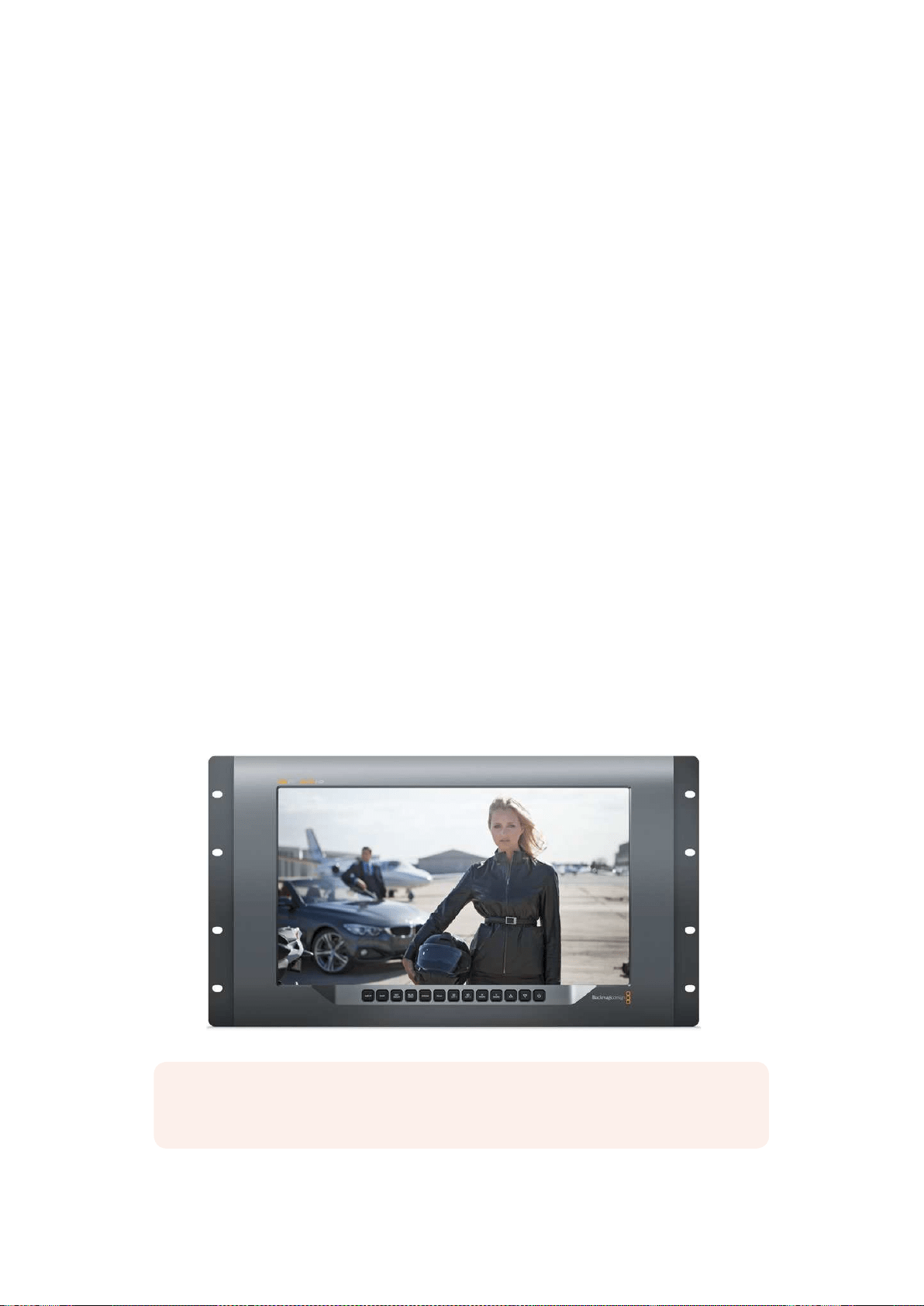
SmartView 4K’nın Kullanımı
Blackmagic SmartView 4K ile Tanışın
SmartView 4K; 2160p60 Ultra HD video’ya kadar SD, HD ve native izleme imkanı sunan, 6 RU
ölçüde, Ultra HD 12G-SDI yayın monitörüdür. Parlak ekranı ve geniş izleme açısı ile SmartView
4K, doğru odak ve renk izleme imkanı için canlı ve net bir görüntü sağlar ve adeta her video
formatını destekler.
Stüdyo ve stüdyo dışı yayın ortamları için tasarlanmış olan SmartView 4K monitörünün kullanımı
inanılmaz derecede kolaydır. Yanlardan montajlı konnektörleri ve VESA desteği mevcuttur.
Ünite, dar alanlara sığdırılabilir veya bir duvara ya da eklemli kol üzerine monte edilebilir.
SmartView 4K, dahili kontrol panel kullanılarak ya da ön panele erişim sağlayamadığınız
durumlarda, Ethernet aracılığıyla uzaktan çalıştırılabilir.
İki adet çoklu hız 12G-SDI girişi, SDI kaynakları arasında seçim yapmanıza olanak sağlarken,
optik fiber SDI modül ilave ederek videonuzu optik fiber yoluyla bağlayabilmeniz için bir SMPTE
uyumlu SFP modül soketi mevcuttur. Video sinyalini başka ekipmanlara yönlendirebilmeniz için
bir 12G-SDI çıkış bulunur. Bununla birlikte ağ oluşturmak için iki Ethernet konnektör, uzaktan
kontrol özelliği ve başka monitörlere seri bağlantı için loop çıkışı mevcuttur. Diğer konnektörler
arasında canlı yapım için bir tally girişi ve dahili yazılım güncellemeleri için de bir USB
port bulunur.
Hatta Blackmagic SmartView kurulum yazılımını kullanarak .cube uzantılı endüstri standardı 3D
LUT’lar veya DaVinci Resolve ile üretilen LUT’lar yüklenebilir. 3D LUT’lar ile SmartView 4K
monitörünüzü kameranıza bağlayabilir ve kliplerinizi son derecelendirme kalitesine en yakın
kalitede izleyebilirsiniz. İki seviyeli focus peaking özelliği, çekimlerinizin kusursuz odaklanmasını
mümkün kılıyor. AC ve DC güç kaynağına destek ile, SmartView 4K monitörünüzü şebeke
prizine veya sette taşınabilirlik için harici bir bataryaya takma esnekliğine sahipsiniz.
SmartView 4K videonuzu SD, HD ve native 3840x2160 piksel çözünürlüğü ile Ultra HD’de
görüntüleyebilmesi sebebiyle, portatif ve stüdyo yayın prodüksiyonu için ideal izleme çözümüdür.
NOT DC güç girişi ile harici güç bağlanıyorsa, harici güç çıkışınızın 12 voltta 24 watt
temin etme kapasitesine sahip olduğundan emin olun.
391SmartView 4K’nın Kullanımı

Kontrol Panel Butonları
Kontrol paneli, bir sıra butona sahip olduğundan, SmartView 4K monitörünüz üzerindeki ayarları
hızla değiştirebilirsiniz.
Giriş
Bu butona bastığınızda, SmartView 4K monitörünün iki adet 12G-SDI girişine bağlı olan video
sinyalleri arasında dolaşım sağlanır. Bir girişte video bağlı bulunmuyorsa, SmartView 4K o giriş
için siyah görüntüler. Girişler arasında geçiş yaparken, bağlı olan giriş formatınız hakkındaki
bilgiler, monitörünüzün üst sol köşesinde anlık olarak sergilenir.
Disp
‘Disp’ butonu, SmartView 4K monitörünüzün LCD ekranının parlaklık ayarının değiştirilmesi için
kullanılır. Yukarı ve aşağı ok butonlarını basarak parlaklığı ayarlayabilirsiniz. Bu ayarı kapatmak
için ‘disp’ butonuna tekrar basın.
Yatay/Dikey (H/V) Gecikme
‘H/V delay’ butonuna bastığınızda, SDI video sinyalinizde yardımcı verinin gömülü olup
olmadığını hızla doğrulayabilirsiniz. Örneğin, yatay yardımcı veriyi izlemek için H/V butonuna bir
kez basın. Genellikle kapalı alt yazı gibi veriler için kullanılan dikey yardımcı veriyi izlemek için,
H/V butonuna tekrar basın.
Yalnızca Mavi
Bir dijital video sinyalinde gürültü mevcutsa, mavi kanalda belirgin bir şekilde görünür. Mavi
kanalınızda gürültü olup olmadığını kolayca kontrol etmeniz için, ‘blue only’ (yalnızca mavi)
butonuna basın. Bu işlem siyah ve beyaz bir görüntü olarak temsil edilen yalnızca mavi kanalını
görüntüler. Bu siyah beyaz görüntü ayrıca, kamera odağını gözden geçirirken de yardımcı olması
amacıyla kullanılabilir.
Zoom
Net bir kamera odağı elde etmenin bir yöntemi, ‘zoom’ butonunu kullanmaktır. Görüntüyü
büyütmek için bir kez basın. Bunu yaptığınızda bir nesnenin odakta olup olmadığını açıkça
görebilirsiniz. Normal izleme boyutuna geri dönmek için tekrar zoom’u tıklayın.
INPUT DISP
H/V
DELAY
3D
LUT 1
BLUE
ONLY
ZOOM PEAK
3D
LUT 2
H
MARK
V
MARK
392SmartView 4K’nın Kullanımı
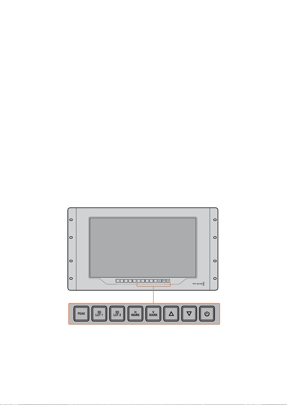
Pik (Peak)
Focus peaking özelliğini etkinleşirmek için ‘peak’ butonunu tıklayarak kameranın odak ayarı
kolaylıkla kontrol edilebilir. Bu, görüntünüzdeki en keskin noktaların çevresinde parlak yeşil bir
kenar çizgisi görüntüler. Peak butonuna tekrar basılmasıyla, aralarında seçim yapabileceğiniz iki
adet peaking keskinliği seviyesi bulunmaktadır. Yeşil kenarları en keskin iken, kameranızın
odakta olduğundan emin olabilirsiniz.
3D LUT 1 ve 3D LUT 2
LUT butonları, görüntünüzü Blackmagic DaVinci Resolve’de üretilmiş veya özel 3D LUT’ları veya
endüstri standardı .cube LUT’ları kullanarak izlemenize imkan tanır. LUT’u etkinleştirmek için LUT
butonuna bir kez basın. LUT’u etkisizleştirmek için tekrar basın. 3D LUT’ların SmartView 4K ile
kullanılması hakkında daha fazla bilgi için, ‘Blackmagic SmartView Setup kullanılarak 3D
LUT’ların Yüklenmesi’ bölümüne bakın.
H Mark ve V Mark
‘H Mark’ ve ‘V Mark’ butonları kullanılarak, kare işaretleyicileri görüntülenebilir ve değiştirilebilir.
Kare işaretleyicileri, görüntülerinizi oluşturmanıza veya önemli bilgi ya da grafiklerin, ekranın
güvenli alanında kalmalarına yardımcı olur. Farklı televizyonlar video sinyallerinin kenarlarını
biraz fazla veya biraz eksik görüntülediklerinden, güvenli alanı görebilmek açısından yararlıdır.
Güvenli alan, görüntüyü izlemek için hangi televizyon veya monitör kullanılıyor olursa olsun,
ekranın mutlaka görüntülenecek alanıdır.
Yatay ve dikey kare işaretleyicilerini görüntülemek için, H Mark ve V Mark butonlarına sırasıyla
basınız. İşaretleyicilere değişiklik yapmak için, kılavuzların her birini vurgulamak üzere ilgili
butonlara tekrar basın. Bu işlem, yukarı ve aşağı ok butonlarının kullanılmasıyla işaretleyicilerin
konumlarını değiştirmenize olanak sağlıyor. Her bir butona tekrar basılması, yeni konumlarınızı
doğrular. Tekrar bastığınızda, işaretleyiciler etkisizleştirilir.
Yukarı ve Aşağı Ok Butonları
Bir ayarı değiştirirken yukarı ve aşağı ok butonlarını kullanın. Örneğin, ekran parlaklığını
ayarlarken veya kare işaretleyicilerin konumlarını değiştirirken.
Güç
SmartView 4K’yı çalıştırmak için, güç butonuna bir kez basın. Kapatmak için tekrar basın.
INPUT DISP
H/V
DELAY
3D
LUT 1
BLUE
ONLY
ZOOM PEAK
3D
LUT 2
H
MARK
V
MARK
393SmartView 4K’nın Kullanımı
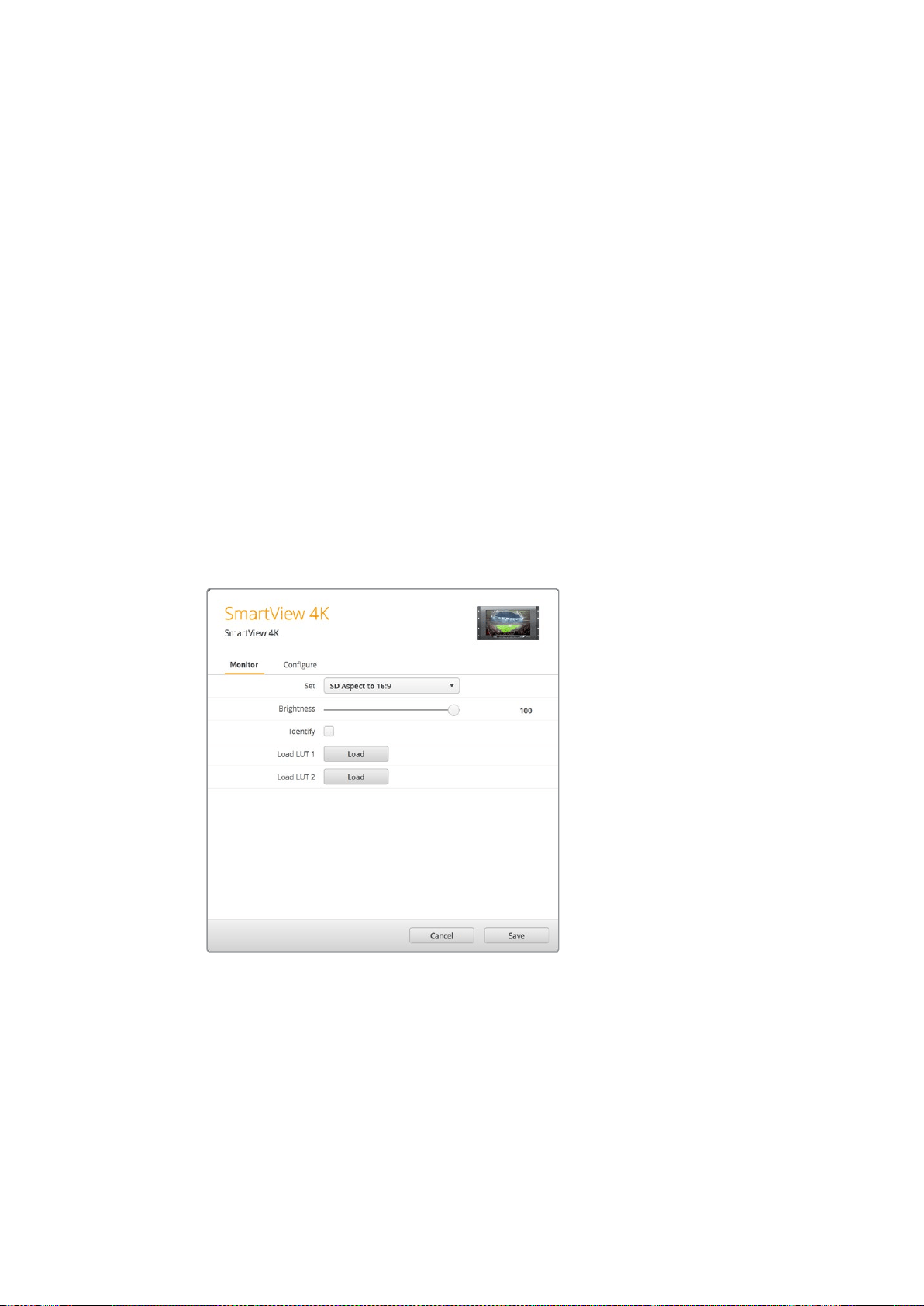
Blackmagic SmartView Setup Kullanılarak
3D LUT’ların Yüklenmesi
SmartView 4K, 3D LUT’lar kullanılarak videonuzun izlenmesini sağlar. Bu özellik, profesyonel
kalibrasyon LUT’ları kullanarak, SmartView 4K’nızı kalibre etmeniz veya videonuzu en son renk
derecesine mümkün olduğunca yakın bir görüntüyle izlemeniz için seçenek sunar. 3D LUT’ları,
farklı görünümleri denemek için de kullanabilirsiniz. LUT’lar, SmartView 4K’ya Blackmagic
SmartView Setup kullanılarak yüklenir. SmartView 4K, .cube dosya uzantılı, endüstri standardı
LUT dosyalarını desteklediğinden, Blackmagic DaVinci Resolve ile üretilen özel LUT’lar dahi
yüklenebilir. LUT’ların oluşturulması hakkında daha fazla bilgi için DaVinci Resolve kullanım
kılavuzuna bakınız.
3D LUT 1 içine bir 3D LUT yüklemek için:
1 Blackmagic SmartView Setup’ı başlatın.
2 ‘Load LUT 1’ yükleme butonuna basın. Yüklemek istediğiniz LUT dosyasının
yerini belirtmenizi isteyen bir pencere açılacaktır. Dilediğiniz .cube LUT
dosyasını seçin, sonra ‘open’ (aç) butonuna basın.
3 Biraz önce yüklemiş olduğunuz LUT’u izlemek için SmartView 4K kontrol
panelindeki 3D LUT 1 butonuna basın. LUT’u kapatmak için butona
tekrar basın.
3D LUT 2’ye bir LUT dosyası yüklemek için aynı işlemi tekrarlayın.
SmartView 4K üzerine 3D LUT yüklemek için
Blackmagic SmartView Setup’ı kullanın.
394SmartView 4K’nın Kullanımı
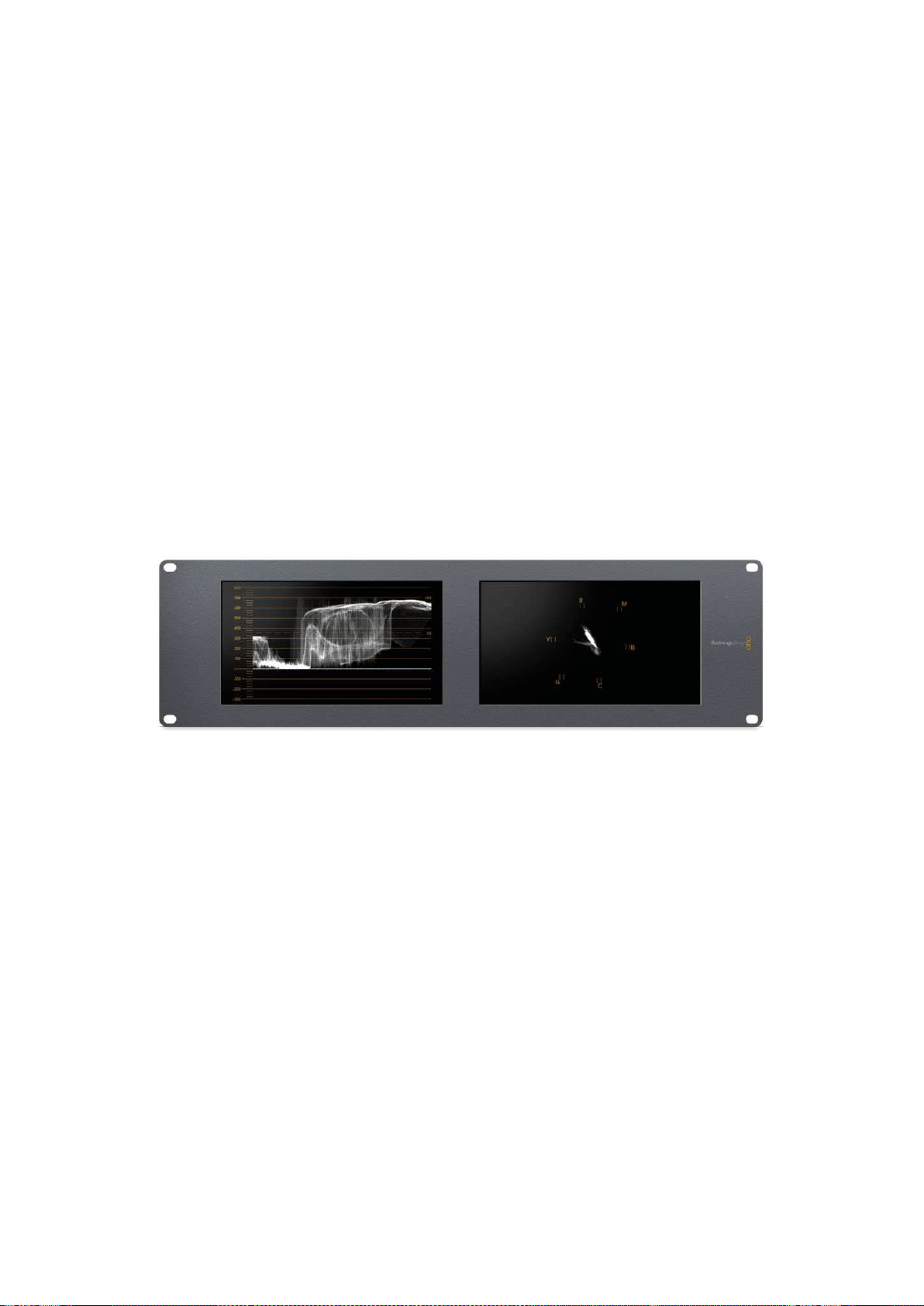
SmartScope Duo 4K Kullanımı
Blackmagic SmartScope Nedir?
Daha önceleri, yayın kalitesinde televizyon ve post prodüksiyon skopları, inanılmaz derecede
pahalı ve küçücük bir ekranda sadece tek bir skopu gösterebilen özel çözümlerdi. Bazı skoplar
kötü bir görünüme sahiptir ve müşterilerinizin de görmelerini istemeyeceğiniz niteliktedir.
SmartScope Duo 4K ile ayrıca waveform (dalga şekli) monitörlerine sahip oluyorsunuz. Bunlar,
çift monitörlerinizde video sinyalinizin herhangi bir açısını gerçek zamanlı olarak izlemenizi
sağlar. Blackmagic SmartView Setup yazılımında giriş sinyaline yaptığınız herhangi bir değişiklik
anında SmartScope Duo 4K’da görülebiliyor. Buna ek olarak, her bir giriş sinyali monitörlerden
herhangi birine SDI loop çıkışı yoluyla iletilebilir. Böylece, soldaki monitöre giden sinyalin
skoplarını görüntülemek için, sağdaki monitörü kullanabilirsiniz.
SmartScope Duo 4K tarafından sergilenen göstergeler, Blackmagic SmartView kurulum
yazılımında seçilir. Aşağı açılan ‘display’ (ekran) menüsünden skoplarınızı seçin.
Aşağıda ve devamındaki sayfalarda açıklanan bilgiler, her bir göstergenin, size ne şekilde
yardımcı olabileceği hakkında daha kapsamlı bir bilgiye sahip olabilmeniz açısından, gösterge
ekranlarının nasıl kullanıldığını açıklamaktadır.
Blackmagic SmartView kurulum yazılımı kullanılarak her bir monitörde farklı bir göstergenin
görüntülenmesi için, Blackmagic SmartScope Duo 4K’nın ayarlanması kolaydır.
Video İzleme Ekranı
Video İzleme ekranı, SmartScope’ye giden video sinyalini görerek, sonuçtan emin olmanızı
sağlayan bir monitördür.
Eğer giriş sinyaliniz SD formatındaysa, aşağı açılan ‘set’ (ayarları kaydet) menüsünden 4:3
pillarbox veya 16:9’da görüntülemesi seçenekleri arasından bir seçim yapabilirsiniz. LCD
ekranının parlaklık, kontrast veya doygunluk ayarlarına yapılan herhangi bir değişiklik, bu ekran
penceresinde anında görünebilir. Aklınızda bulunsun ki, bu ayarların değiştirilmesi video
sinyalini değil, sadece monitörü etkiler. Dolayısıyla, yapacağınız herhangi bir doygunluk veya
parlaklık değişikliği göstergeleri etkilemeyecektir.
395SmartScope Duo 4K Kullanımı
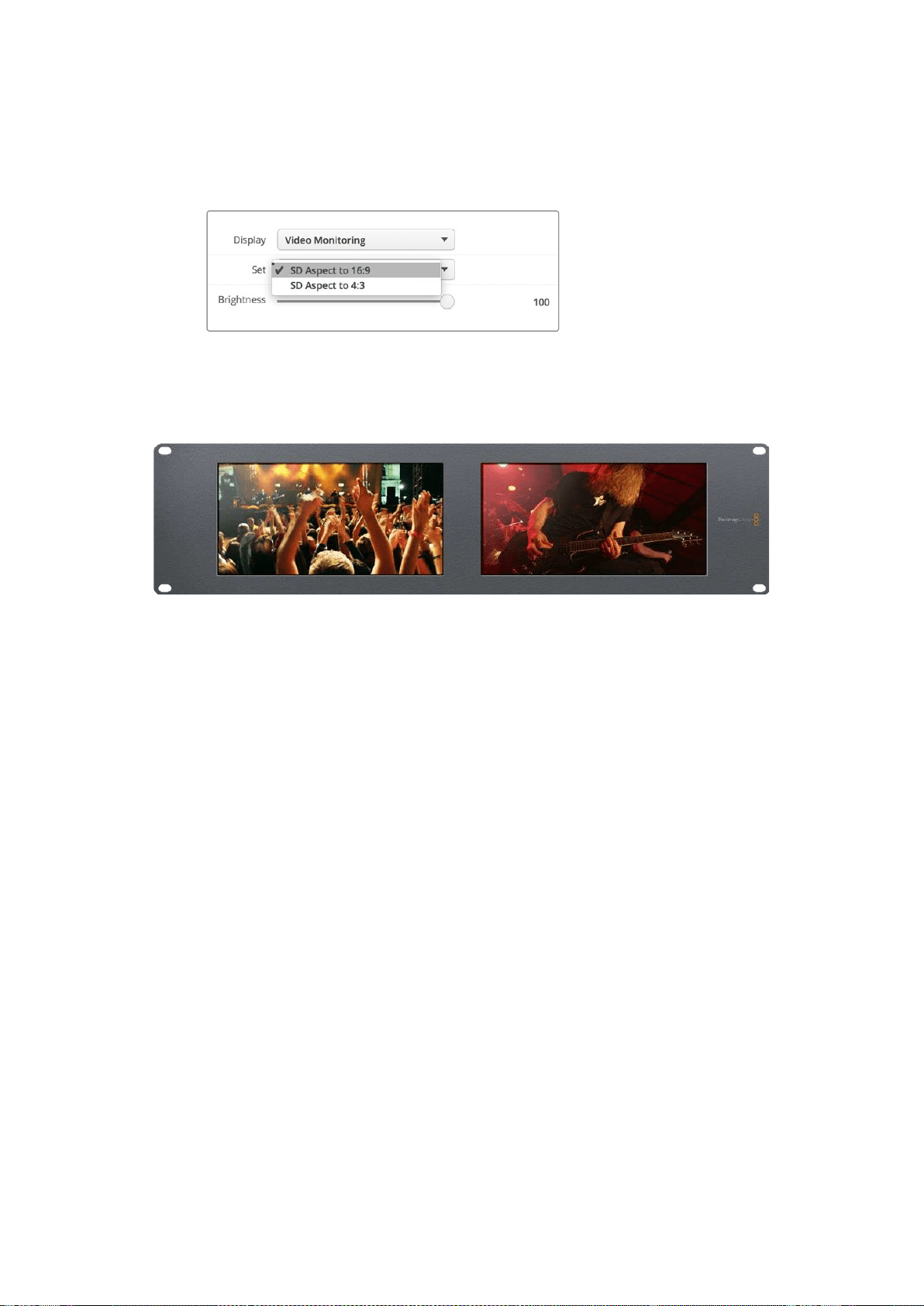
Monitörlerden birini ‘video izleme’ monitörü olarak ayarlayıp, bir diğerini de skop ekranı olarak
ayarlamanız işinizi kolaylaştırabilir. Bunu yapmak için, ‘monitör 1’ SDI loop çıkışını ‘monitör 2’ SDI
girişine bağlamak için kısa bir kablo kullanın.
Blackmagic SmartView setup’daki ‘set’ menü seçeneklerinden
seçerek, SD videoyu 4:3 pillar box veya 16:9 geniş ekran
modunda izleyebilirsiniz. Anamorfik standart tanımlı
video izlerken “SD Aspect to 16:9” olarak ayarlayın.
Video izleme ekran ayarı, video sinyalinin bir televizyon ekranı veya
monitörde, görüntünün normalde görüneceği haliyle gösteriyor.
Waveform (Dalga Şekli) Ekranı
Waveform ekranı, geleneksel parlaklık waveform monitörleri gibi dijital olarak kodlanmış bir
waveform sunar, bu da video sinyalinin luma (parlaklık) seviyesinin izlenmesi ve düzeltilmesi
için kullanılır.
Geleneksel parlaklık waveform monitörleri, yalnızca composite analog standart tanımlı videoyu
destekliyorlardı. Ancak, SmartScope Duo 4K’nın waveform ekran penceresi Ultra HD ve HD’nin
yanında SD formatında da çalışıyor. Böylelikle, yüksek çözünürlüklü dijital video formatlarını
izlerken bile, luma seviyelerini düzeltmenin tutarlı ve kolay bir yöntemine sahip oluyorsunuz.
Blackmagic SmartView setup yazılımındaki aşağı açılan display (ekran) menüsünden, ‘waveform’
(dalga şekli) opsiyonunu seçin. İllegal (yayına uygun olmayan) luma değerlerine karşı önlem
almak için, waveform göstergesindeki siyahlarınızın %0’ın altına düşmediğinden ve beyazların
ise %100’ün üzerine çıkmadığından emin olun.
Waveform monitörü, görüntünün grafiksel bir temsilidir ve kare içinde bulunan luma değerlerine
ilişkin aynı konumda olan luma değerlerini gösterir. Örneğin, gökyüzünün bir kısmı aşırı
pozlanmışsa, waveform ekranında da, karede belirdiği aynı yatay konumda görünecektir.
Kamera çekimlerinize bağlı olarak, waveform göstergesi farklı görünecektir. Yüksek kontrast
içeren bir video izlediğinizde, orta grilerdeki değerleri göremeyebilirsiniz. Aşağıdaki resim,
solda koyu bir alan ve karenin ortasından sağa doğru daha parlak değerlere sahip, eşit bir
şekilde pozlanmış bir görüntünün dalga şekli değerlerini göstermektedir.
396SmartScope Duo 4K Kullanımı

Parlaklık değerlerini gösteren waveform göstergesi
Blackmagic SmartView setup ‘display’ (ekran) ayarlarından
‘waveform’ opsiyonunu seçerek, video sinyalinizdeki
parlaklık değerlerini izleyebilirsiniz
Vektörskop Ekranı
Vektörskop ekranı bir video sinyalindeki renkleri göstermeye yarayan bir vektör görüntüleme
modu kullanır. Tesisinizde kullanılan renk çubuğu test sinyallerinin standardına bağlı olarak,
Blackmagic SmartView setup yazılımındaki aşağı açılan ‘set’ menüsünden %100 veya %75
opsiyonunu seçin.
Bazı insanlar vektörskopun illegal (yayına uygun olmayan) seviyelerin kontrolü için kullanıldığını
düşünürler ancak, bu doğru değildir. Tüm illegal renklerin kontrolü için Parade RGB ekranı
kullanılmalıdır. Vektörskopu, illegal seviyeleri kontrol etmek için kullanamıyor olmanızın sebebi,
hem chroma hem de parlaklık değerlerine gereksinim olmasıdır. Örneğin, videodaki beyaz veya
siyah noktalara yakın renkler, orta grilerde kullanılabilen çok daha keskin renklerdeki kadar
doygun olamazlar. Vektörskop ekranı, parlaklık değerlerini değil, sadece renkleri
gösterdiğinden, sadece illegal renkleri kontrol etmek üzere kullanılamaz.
Vektörskop ekranı, chroma seviyelerinin düzeltilmesini gerektiren daha eski, analog video
kasetlerindeki renk seviyelerini kontrol etmek için en iyi araçtır. Video kasetinin renk çubuğu
bölümünü oynatın ve sonra, gratiküldeki (enlem boylam çizgisi) kare kutular kapsamında
videonun renklerini ayarlamak üzer, chroma ve hue (renk tonu) ayarlarını düzeltin.
397SmartScope Duo 4K Kullanımı
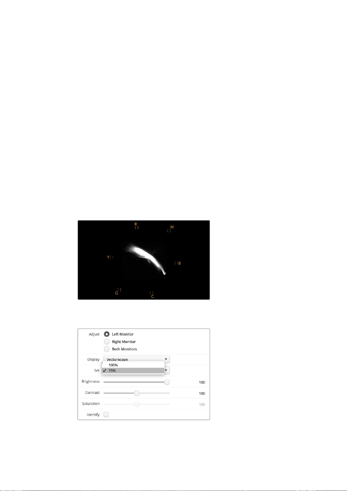
Vektörskop ekranı renk derecelendirme işlemleri için de mükemmeldir çünkü, videonuzun
beyaz ayarının doğru olup olmadığını veya bir renk tonu olup olmadığını kolayca kontrol
edebilirsiniz. Videonuzda bir renk tonu varsa, vektörskop ekranı merkezden sapar ve
merkezinde iki nokta görünebilir. Normalde video sinyalindeki blanking (karartma) işlemi
vektörskopun merkezinde bir nokta oluşturur. Bunun nedeni, videodaki kararmanın içinde hiç
bir renk barındırmayan bir siyah olmasıdır. Blanking özelliği, renk bilgisi olmayan siyah video
bölümlerini tespit etmekte faydalı bir referans noktası sağlıyor.
Videonuzda bir renk tonu mevcutsa, siyahların bulunduğu renkten ve merkezden sapmalarını
gözlemleyebilirsiniz. Sapma oranı videonuzdaki renk tonunun miktarını belirler. Bu sapma
videonuzun hem beyaz hem de siyah detaylarında görülebilir. Bu özellik, renk tonunun
giderilmesinde ve doğru beyaz ayarın yapılmasında, vektörskopu değerli bir araç kılar.
Vektörskop ekranı, siyahlara veya beyazlara yanlışlıkla istenilmeyen renk tonları katmadan,
videonuzdaki renklerin sınırlarını zorlamanızı sağlar. Renk dengesi, hem RGB parade hem de
vektörskop görüntüsünde izlenebilirken, renk dengesindeki olası sorunlar genelde vektörskop
görüntüsünde daha kolay görülebilir.
Özellikle yüz bölgesi olmak üzere, cilt tonu içeren çekimlerin renk düzeltmelerini yaparken,
sıcak renk doygunluğunun değerini, vektörskop üzerinde saat 10’u gösteren bir açıda, eşit bir
çizgide tutmanız gerekecektir. Bu “fleshtone line” (cilt rengi çizgisi) olarak adlandırılır ve cilt
yüzeyinin altındaki kanın rengine bağlı olarak belirlenir. Fleshtone çizgisi her türlü cilt
pigmentasyonu için uygulanabilir ve videonuzdaki kişilerin cilt tonlarının doğal görünmesini
sağlamanın en iyi yoludur.
Saat 10’u gösteren bir konuma doğru eğilimli ‘fleshtone
çizgisini’ gösteren bir vektörskop ekranı
Vektörskopunuzu %100 veya %75 renk çubuğu test
sinyallerine ayarlayın
398SmartScope Duo 4K Kullanımı
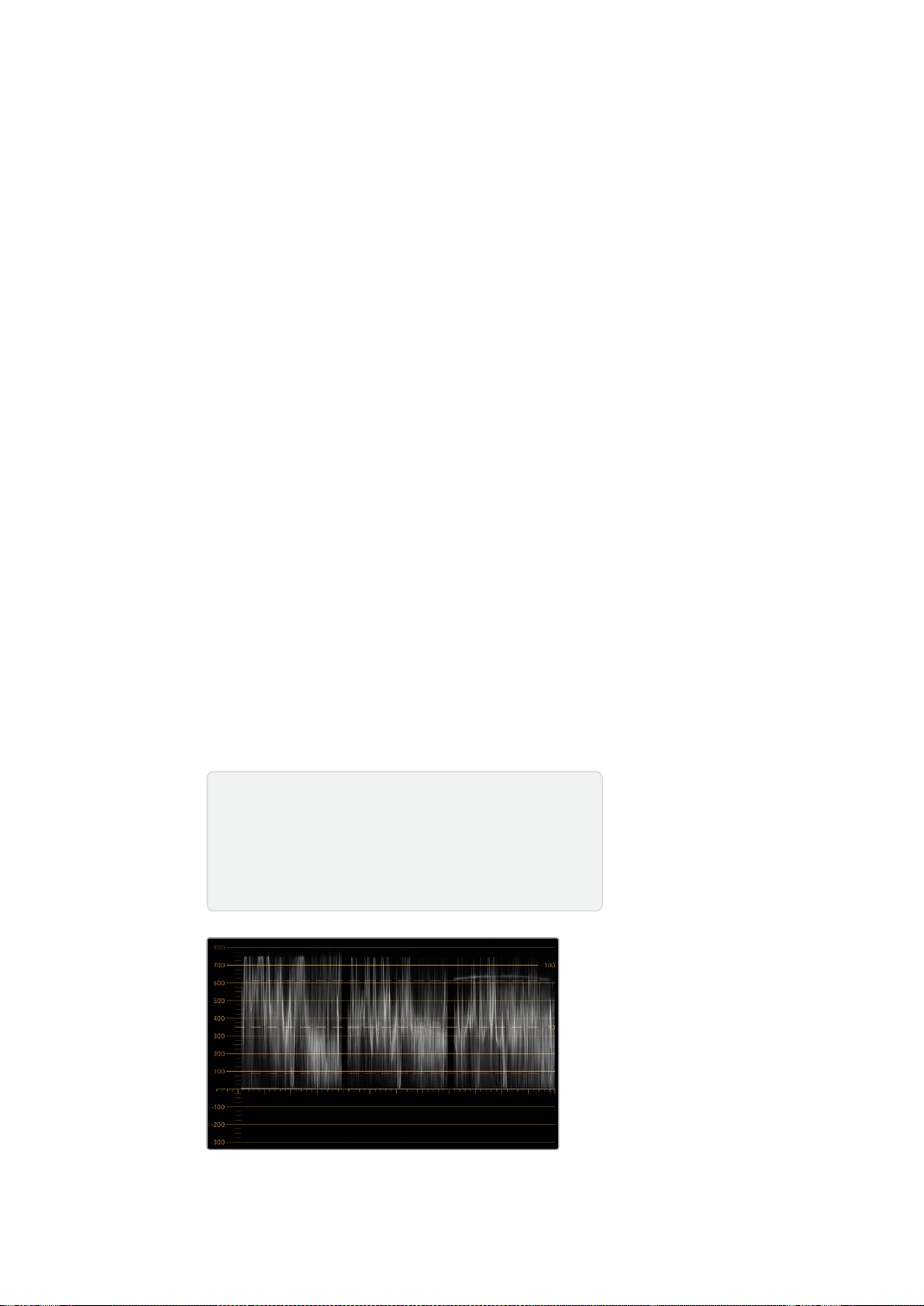
Parade Ekranı
RGB ve YUV parade ekranları renk düzeltme, illegal (yayına uygun olmayan) renkleri kontrol
etmek ve seviyeleri kontrol etmek için harikadır.
Renk düzeltme işlemi yaparken, Blackmagic SmartView kurulum yazılımındaki aşağı açılan
‘display’ (ekran) menüsünden RGB parade opsiyonunu seçin. RGB parade penceresi, münferit
kırmızı, yeşil ve mavi renk kanallarının tam boyunu görüntüler. Renk kanallarının her birinin
izlenmesi, renk düzeltme sürecini kolaylaştırıyor. Ayrıca, video sinyalindeki siyahların, orta
tonların ve beyazların renk dengesini izlemek de kolaydır. RGB parade; kırmızı, yeşil ve mavi
kanalları arasındaki ortak nitelikleri tespit etmenizi sağlayarak, arzu edilmeyen renk tonlarını
gidermeyi ve renk dengesini ayarlamayı kolaylaştırır.
Renk düzeltme işlemleri yaparken, video seviyelerinin full olduğundan fakat clipping’e maruz
kalmadığından emin olmanız önemlidir. Video seviyesini artırmak isterseniz, RGB sınırının üstüne
çıkmadığından emin olunuz. Aksi takdirde, illegal seviyeler oluşacaktır. Bazı ekipmanlar illegal
%100 seviyelere ulaşmanızı engellerken, başka ekipmanlarda böyle bir önlem yoktur.
SmartScope Duo 4K illegal seviyeleri, oluştukları an görmenizi sağlar.
İllegal video seviyeleri siyah ve beyaz seviyelerinde de oluşabilir. Bazı renk düzeltme
sistemlerinde, siyah seviyeleri %0 olan siyah noktasının altına indirilebilmektedir. Videonuzda
illegal siyah seviyeler tespit ederseniz, bunları gidermek için biraz “lift” veya gain ilave etmeniz
yeterlidir ancak, video sinyalinin tamamının lift işlemine maruz kalmadığından ve beyazlarda
illegal renkler üretmediğinden emin olmak üzere %100 gratikül seviyesini kontrol edin.
YUV seviyelerini kontrol etmek için, aşağı açılan ‘display’ menüsünden YUV parade ibaresini
seçin. Bu görüntü penceresi faydalıdır çünkü luma (parlaklık) değerleri chroma (renk)
değerlerinden ayrıştırılmıştır. Bu da, televizyon yayını için olan video sinyalleri formatıdır. Soldaki
waveform luma bilgilerini ve ikinci ile üçüncü waveform’lar da chroma bilgilerini gösteriyor.
YUV parade penceresi, bir video sinyalinin chroma değerlerini bir renk çubuğu test düzenine
(pattern) kalibre etmek için faydalıdır. Böylelikle, renkler doğru bir nitelikte temsil edilir ve
yayınlanan sinyal televizyon ekranlarında görüntülenebilir.
Renk düzeltme işlemi, illegal seviyeler oluşturmadan en iyi görünüme sahip görüntüler elde
etmeye yarayan sonsuz bir ayarlama sürecidir.
RGB parade görüntüleme
Renk Düzeltme Terminolojisi
Blacks (Siyahlar) – Video sinyalindeki siyah seviyeleri
Mids (Orta Tonlar)– Video sinyalindeki orta-gri seviyeleri
Whites (Beyazlar) – Video sinyalindeki beyaz seviyeleri
399SmartScope Duo 4K Kullanımı

YUV parade görüntüleme
Blackmagic SmartView setup’taki aşağı açılan ‘display’ (ekran) menüsünden
RGB parade ile YUV parade opsiyonları arasından seçin.
Histogram Ekranı
Grafik tasarımcıların ve kamera operatörlerinin en aşina oldukları ekran histogram penceresidir.
Histogram, beyazdan siyaha doğru olan bilgilerin dağılımını gösterir ve görüntülerdeki ayrıntıların,
videonun beyazlarında veya siyahlarında clipping’e maruz kalmaya ne kadar yakın olduğunu izleminizi
sağlar. Histogram ekranı ayrıca, videodaki gamma değişikliklerinin etkilerini görmenizi sağlar.
Ekranın solu siyah videoyu gösterirken, sağ tarafı da beyazları göstermektedir. Videonun tamamı
genelde histogram ekranının %0 ila %100 zaman aralıkları arasında bulunmalıdır. Videonuz %0’ın
altına veya %100’ün üzerine geçtiği an clipping’e maruz kalır. Çekim sonrası kontrollü bir ortamda
renk düzeltme işlemleri yapmak istediğiniz durumlarda, siyah ve beyazlardaki ayrıntıların mutlaka
muhafaza edilmesi gerektiğinden, çekim yaparken videodaki görüntülerin clipping’e maruz
kalması çok kötü bir sonuç doğurabilir. Çekim yaparken videoyu siyah klibin üzerinde ve beyaz
klibin altında tutun. Böylelikle, beyazların ve siyahların mat ve ayrıntıdan yoksun görünmesini
engelleyerek daha sonradan renkleri düzeltmek için daha fazla özgürlüğe sahip olursunuz.
Renk düzeltme yaparken, videonuza clipping işlemi uygulamak isteyebilirsiniz. Bu durumda,
histogram ekranı clipping’in video üzerindeki etkisini ve clipping işlemine ne kadar maruz
kaldığını gösterecektir. Clipping’e daha az maruz kalmış, daha fazla ayrıntı içeren benzer bir
görünüm oluşturmak için gamma dahi kullanabilirsiniz.
Histogram ekranını illegal (yayına uygun olmayan) seviyeleri kontrol etmek için pek
kullanamazsınız ancak, illegal siyahları ve beyazları görmek için kullanabilirsiniz. Histogram
ekranı renkleri göstermediğinden, videonuz illegal renkler içermesine rağmen histogram legal
(yayına uygun olan) seviyeleri gösteriyor gibi görünebilir. Bu durumda da RGB parade ekranı,
illegal seviyeleri video sinyalinin hem renk hem de parlaklık öğelerinde yansıttığından, bunları
kontrol etmenin en iyi yoludur.
400SmartScope Duo 4K Kullanımı
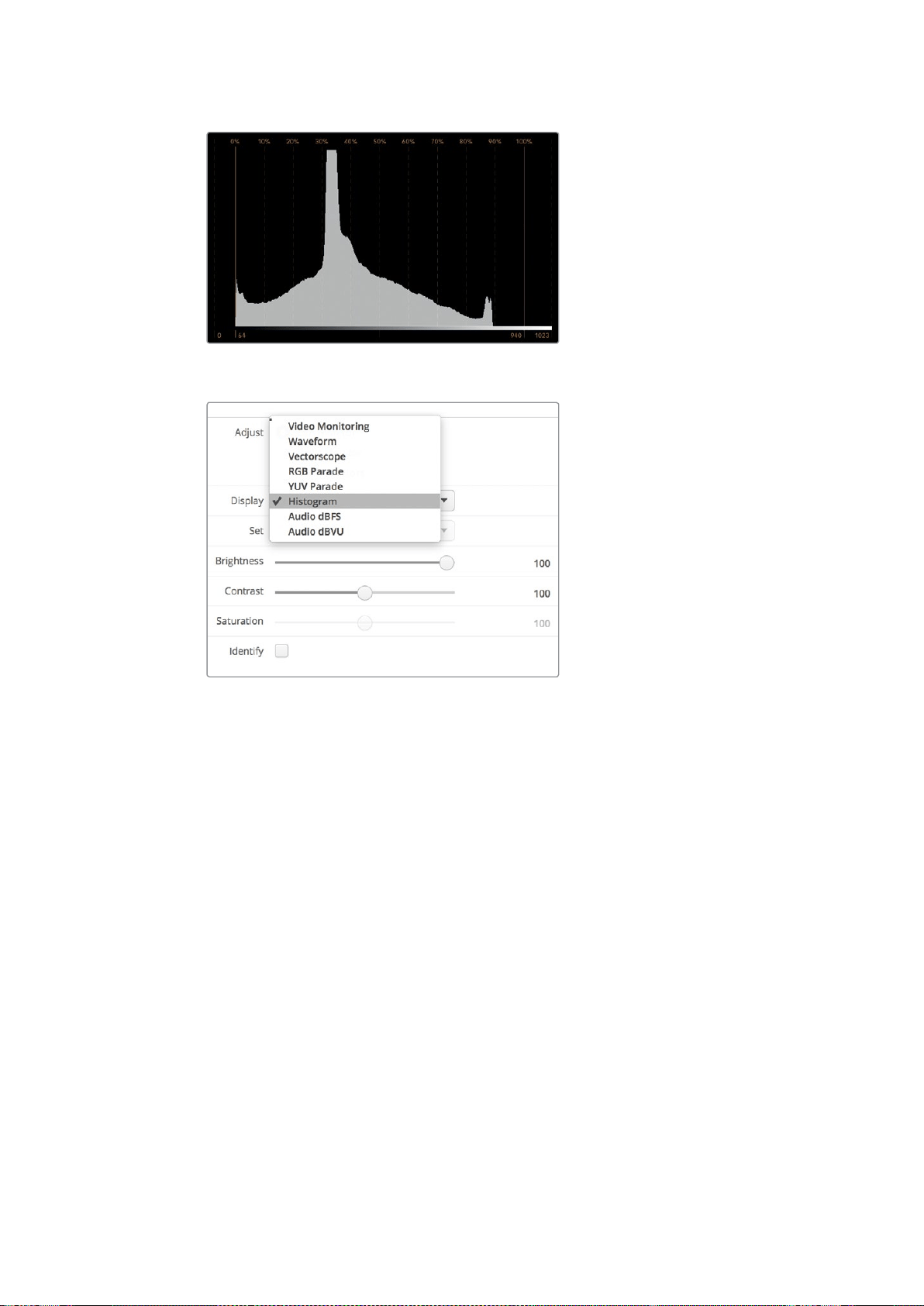
Histogram ekran ayarı, beyazlar ile siyahların dağılımını gösterir
Blackmagic SmartView kurulum yazılımındaki aşağı açılan ‘display’
(ekran) menüsünden histogram opsiyonunu seçin.
Ses Göstergeleri Ekranı
Ses göstergeleri ekranı, SDI video sinyalinin gömülü (embedded) ses kayıtlarındaki ses
seviyelerini gösterir. 16 kanala kadar gömülü (embedded) ses önce ayrıştırılır (de-embedded)
sonra da, dBVU veya dBFS formatında görüntülenir.
VU sayacı ortalama sinyal seviyesini gösterir, kullanımı kolaydır ve daha eski ekipmanlarda
yaygındır. VU metre, SMPTE tarafından önerilen referans değeri olan ve -20 dBFS’ye ayarlı,
1 kHz test ton sinyaline kalibre edilir.
dBFS esasında genel dijital ses sinyalinin bir ölçeğidir ve modern dijital ekipmanlarda yaygındır.
Sağ taraftaki ses skopu iki ses kanalını izleyebiliyor. Bu kanalları aşağı açılan ‘set’ menüsünden
seçebilirsiniz. Örneğin, kanal 1 & 2, kanal 3 & 4, vb. Ses skopu, sesi X-Y görüntüleme olarak
sunar. Böylece, ses dengesindeki sorunları, faz dışı ses koşullarını ve bir ses kanalının mono mu
yoksa stereo mu olduğunu görebilirsiniz. Mono ses tek bir dikey “in phase” (fazda) satır olarak
belirecektir. Eğer çizgi yataysa, ses “faz dışı” demektir ve başka ekipmanlara iletildiğinde
sıfırlanabilir (yani ses kaybı oluşabilir). Ses fazı, büyük tesislerde, kabloların yanlış bağlanması
sonucu karşılaşılan en yaygın sorunlardan bir tanesidir.
Stereo sinyallerini izlerken, sol ve sağ ses kanalları arasındaki farkı temsil etmek üzere,
sağ taraftaki ses skopun çizgisi dışa doğru yayılır. Ses kanalında ne kadar fazla stereo sesi
bulunuyorsa, çizgi bir o kadar dairesel görünecektir. Eğer ses minimal seviyede stereo içerik
bulunduruyorsa, bu durumda skop dikey ekseni çevresinde daha yoğun görünecektir.
401SmartScope Duo 4K Kullanımı
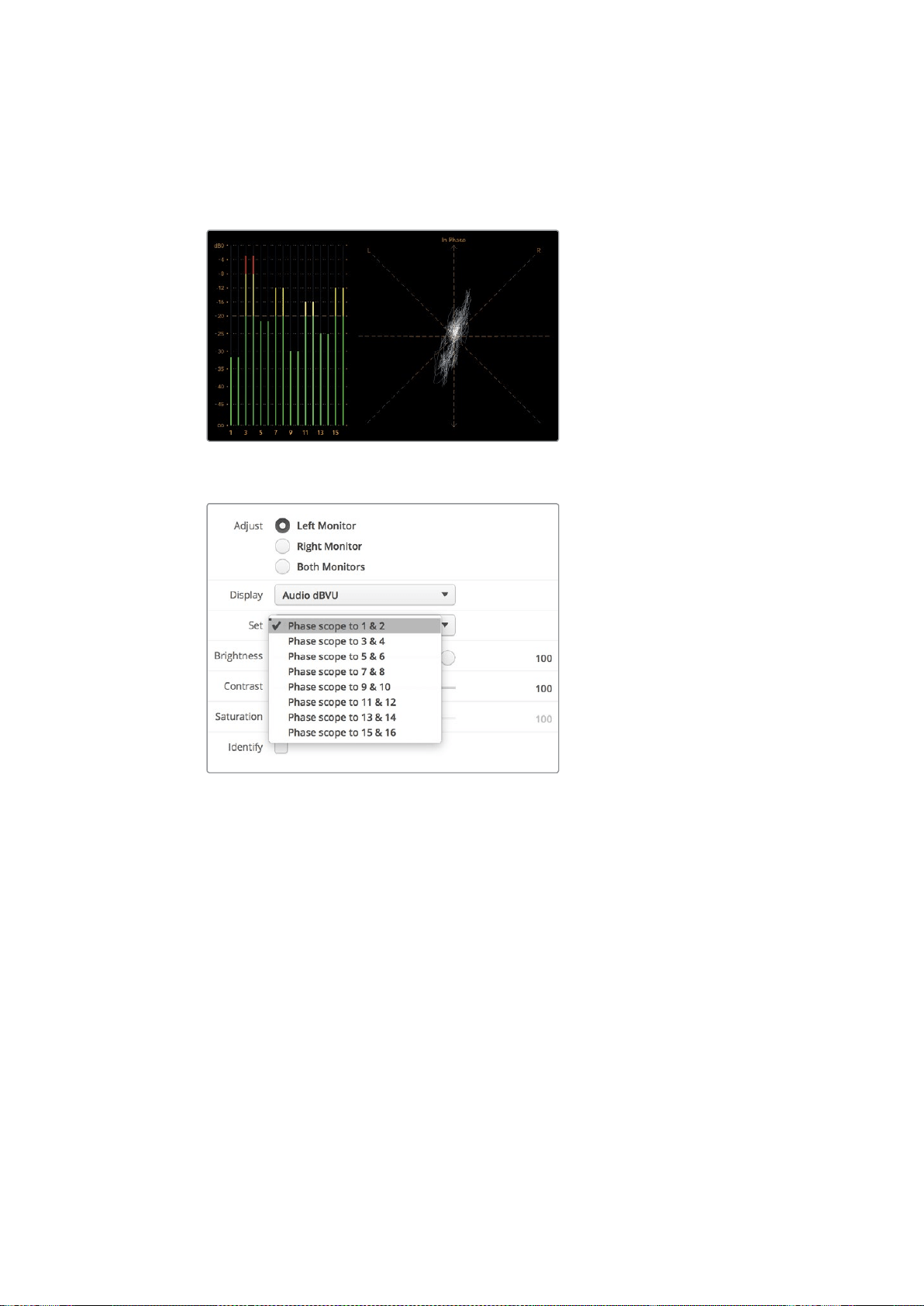
Diyalog sesi genelde dikey bir çizgi olarak görünür. Oysa fazla miktarda stereo içeriğe sahip
olan müzik, skopun dışa doğru yayılmasına sebep olur. Bunun sebebi mono sesin L+R olması ve
dikey eksen üzerinde görüntülenmesidir. Halbuki, stereo içerik L-R’dir ve stereo farkı yansıtmak
üzere yatay eksen üzerinde görüntülenir.
Pik seviyeleri ve ses dengesini gösteren ses gösterge ekranı
Aşağı açılan “Set” menüsünü kullanarak,
izlemek istediğiniz ses çiftini seçiniz.
Bir Ağa Bağlanırken
Bir SmartView veya SmartScope monitörünü bir ağa bağlayarak, birden fazla ünitenin ayarlarını
uzaktan düzeltebilirsiniz.
SmartView ve SmartScope monitörleri herhangi bir yapılandırma gerektirmeden videoyu
görüntüledikleri için, yapılması gereken herhangi bir ağ ayarı, etkinleştirilmeden önce
yapılandırılmalıdır. Ağ yapılandırması yalnızca, bir bilgisayara doğrudan USB bağlantısıyla uygulanabilir.
402Bir Ağa Bağlanırken
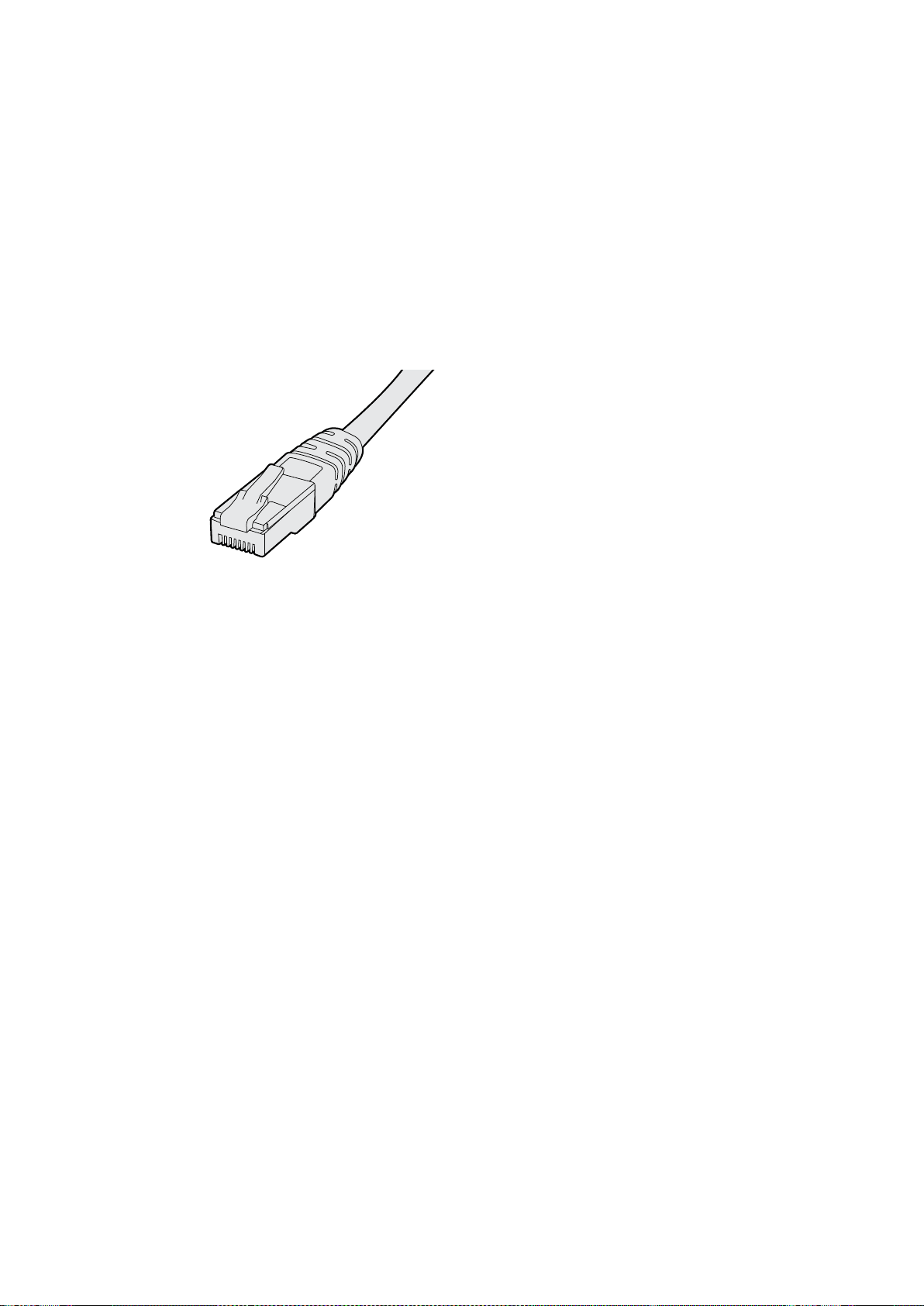
Doğrudan Ethernet Bağlantısı
Bir monitörün uzaktan yapılandırılması, bilgisayarınıza yapılan direkt Ethernet bağlantısıyla
uygulanabilir. Bu yapılandırmada herhangi bir ağ anahtarına gerek yoktur. Bu da, hızla kurulum
ve düzenleme yapmanız gerektiği durumlarda harikadır. Her bir ünitenin üzerindeki aktif
loop-through Ethernet çıkış portu kullanılarak, ek üniteler birbirine seri şekilde bağlanabilir.
Zincirdeki tüm ünitelere güç beslemesi yapılmalıdır.
Mevcut stüdyo ağınızda bulunan IP adreslerini kullanmadan çok sayıda üniteyi bağlamak
isterseniz veya mevcut bir ağınız yoksa, onları doğrudan bilgisayarınızdaki Ethernet portuna
bağlayın. Bu yöntem ayrıca SmartView ve SmartScope ünitelerini Ethernet yoluyla bağlamanın
hızlı bir yoludur çünkü, bir ağ anahtarına herhangi bir kablo uzatmanız gerekmemektedir.
Ethernet Konnektörü
Ethernet Ağ Anahtarı
Stüdyonuzun ağına birkaç tane ünite bağlamak istiyorsanız, ağ anahtarına sadece bir SmartView
veya SmartScope ünitesi bağlamanız yeterlidir. Diğerleri ise, her bir ünitenin üzerindeki aktif
loop-through Ethernet çıkış portu kullanılarak birbirine seri şekilde bağlanabilirler. Böylelikle,
anahtar (switch) üzerinde yalnızca tek bir port kullanılmış olur. Böylece, bir ağ anahtarına birden
çok sayıda kablo uzatmanız gerekmeyecektir. Seri bağlantı (daisy-chaining) özelliğinin çalışması
için tüm ünitelere güç sağlanmalıdır.
Bir ağ anahtarına bağlanmak, ağ üzerinde bulunan herhangi bir bilgisayarın, herhangi bir ünitenin
ayarlarını değiştirmesine olanak sağlıyor. Ağınız, kablosuz erişim noktası içeriyorsa, bir WiFi
bağlantısı yoluyla herhangi bir Mac veya Windows dizüstü bilgisayarıyla da ayarlar değiştirilebilir.
Bir IP bazlı yerel alan ağına SmartView veya SmartScope ünitenizi bağlamak için, aşağıdaki
basamakları uygulamanız gerekecektir.
1 Ünitenizle gelen güç kaynağını güvenli bir şekilde bağlayıp çalıştırın.
2 Üniteyi standart bir RJ45 Ethernet kablosu ile bir ağ anahtarına veya
doğrudan bilgisayara bağlayın.
403Bir Ağa Bağlanırken
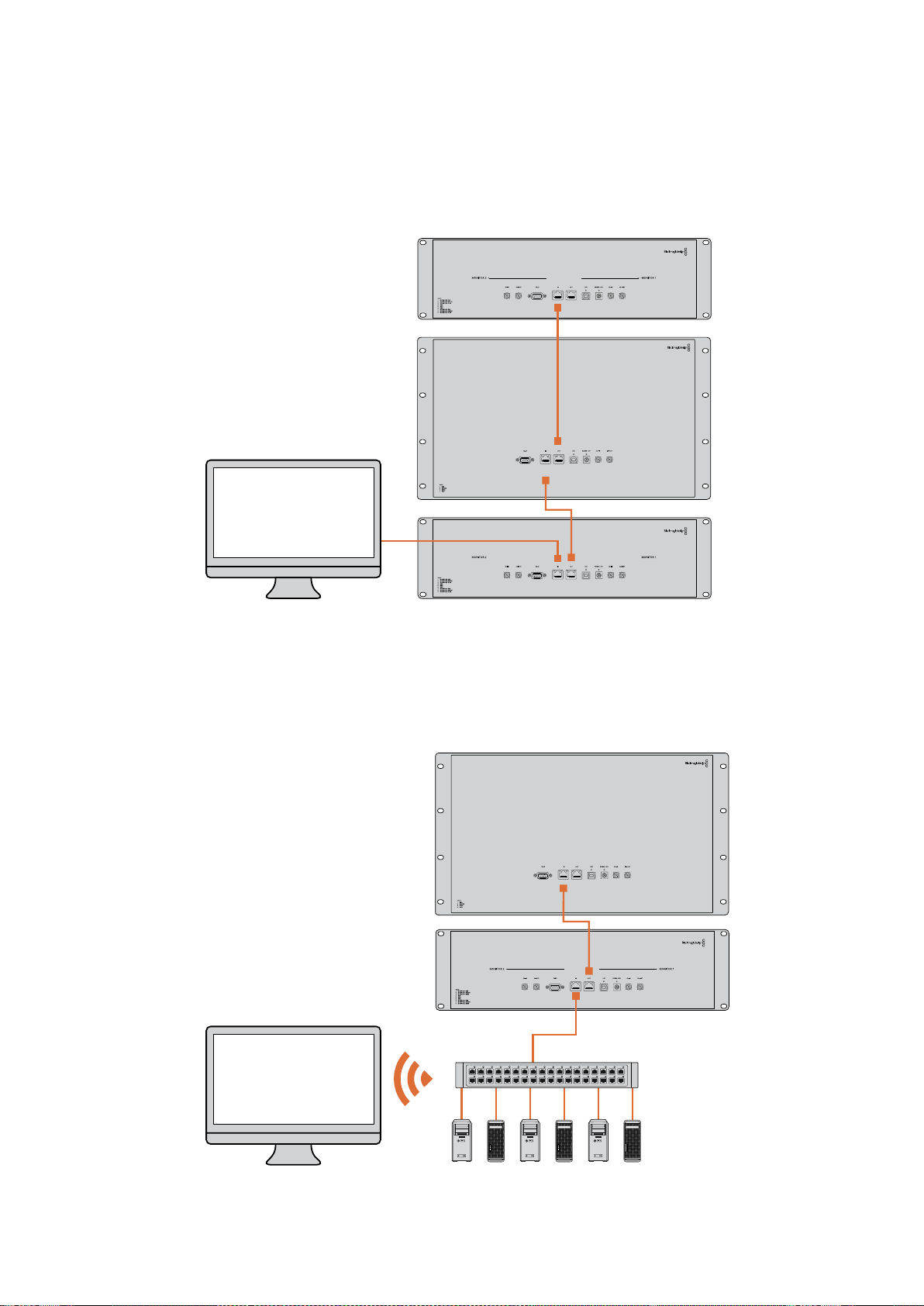
Doğrudan Ethernet Bağlantı Şeması
Bir ağ anahtarına gereksinim olmadan, bir bilgisayarın Ethernet portunu üniteye direkt
bağlayabilirsiniz. Bir ağ anahtarına birden çok kablo uzatmanıza gereksinim kalmaması için,
ek üniteler birbirine seri şekilde bağlanabilir. Tüm ünitelere güç sağlanmalıdır.
Ethernet Ağ Anahtarı Bağlantı Şeması
Stüdyonuzun mevcut ağına birçok ünite bağlamak istediğiniz takdirde, ağ anahtarına ünitelerin
yalnızca bir tanesini bağlamanız gerekecektir. Bir ağ anahtarına birden çok kablo uzatmanıza
gereksinim kalmaması için, diğerleri birbirine seri şekilde bağlanabilir. Tüm ünitelere güç sağlanmalıdır.
SmartScope 4KDuo
SmartScope 4KDuo
Ağ Anahtarı
Ethernet
Client
Bilgisayarlar
404Bir Ağa Bağlanırken

Ağ Ayarlarının Değiştirilmesi
Ağ Ayarları
Cihaz Adı
Her bir SmartView veya SmartScope ünitesinin ağ üzerinde kolayca ayırt edilebilmesi için,
monitörünüzün adını değiştirmenizde yarar vardır. Örneğin, “Saha Kameraları 1 & 2”, “Multi-View
Çıkış”, “4K sinyaller” vb.
Monitörünüzün adını değiştirmek için, monitörünüzün Ethernet veya USB ile bağlı olduğundan
emin olun. Blackmagic SmartView kurulum yazılımını başlatın ve monitör adının altındaki ayarlar
ikonunu tıklayın. Ayarlar sayfasında, ‘network’ ibaresini tıklayın ve ‘details’ (bilgiler) bölümünde
bulunan monitör adını değiştirin. Yazılım, geçersiz bir ad tespit ederse, siz yeni adı tuşlarken,
ad yanında bir uyarı ikonu belirecektir. Belirtilen ad geçersiz ise, yeşil bir işaret belirecektir.
Ad değişikliğini teyit etmek için bilgisayar klavyesi üzerindeki ‘return’ sekmesine basın.
Ağ Ayarları
Blackmagic SmartView kurulum yazılımındaki ağ ayarları bölümüne değişiklikler yapmak için,
Blackmagic monitörünüzün bilgisayara bir USB ile bağlı olması gerekmektedir. Ağ ayarları
Ethernet aracılığıyla değiştirilemez.
Varsayılan ayarları olarak, SmartView ve SmartScope üniteleri ağınızdan otomatik olarak bir IP
adresi atamak üzere DHCP protokolünü kullanır.
Bir DHCP sunucusunun olmadığı durumlarda, doğrudan bağlı olan ünitelere DHCP adresleri
atamak için, macOS’in “internet paylaşımı” (internet sharing) özelliğini veya Windows 8.1 ya
da Windows 10 sistemlerinin “internet bağlantı paylaşımı” (internet connection sharing) (ICS)
özelliklerini etkinleştirmenizde yarar vardır. Böylelikle, her bir üniteye manuel olarak bir sabit IP
adresi atama gereksinimi ortadan kalkar. Bilgisayarınızın bir internet bağlantısı olmasa dahi, DHCP
adreslerini atamak için bu özelliği kullanabilirsiniz. macOS ile Windows 8.1 ve 10 sistemlerinin
Yardım dokümantasyonlarında, internet paylaşımı hakkında ayrıntılı bilgi bulabilirsiniz.
Sisteminizin yapılandırmasında DHCP protokolü kullanılamıyorsa, adresi “sabit IP” kullanarak
yapılandırmayı tercih edin. Ağınızda bir IP çakışmasına sebebiyet vermemek için, lütfen sistem
yöneticinizden yedek bir IP adresi talep ediniz. Her bir SmartView ve SmartScope ünitesine,
kendine özgü bir IP adresi ve ortak bir altağ maskesi belirlemeniz gerekecektir. Ünitelerinizi
Internet yönlendiricisi gibi bir ağ geçidine bağlamayı düşündüğünüz durumlar hariç, “geçit”
(gateway) alanındaki varsayılan değeri değiştirmenize gerek yoktur.
Ağ üzerinde herhangi bir SmartView veya SmartScope monitörü bulunamamışsa, ünitelere
DHCP yoluyla bir IP adresi atanmamış olabilir. Bu durumda, her bir üniteyi uygun ağ ayarlarıyla
manuel olarak yapılandırmanız gerekecektir.
1 USB kullanarak, Blackmagic SmartView veya SmartScope monitörünüzü
bilgisayarınıza bağlayın ve Blackmagic SmartView kurulum yazılımını başlatın.
2 Bağlı olan monitörünüz SmartView Setup ana sayfasında otomatik olarak
görüntülenecektir ve adının yanında bir USB ikonu belirecektir.
3 Monitörünüzün ağ ayarlarını düzeltin.
4 DHCP ile bir IP adresi atanmamış olan diğer üniteler için de bu basamakları tekrarlayın.
405Ağ Ayarlarının Değiştirilmesi

Monitörünüzün adının yanındaki USB ikonu, monitörün bilgisayarınıza
USB ile bağlı olduğunu gösterir. Ağ ayarlarını düzeltebilmeniz için,
Blackmagic monitörünüzün USB ile bağlı olması gerekmektedir.
Ağ ayarları DHCP veya bir sabit IP adresi kullanmak üzere
ayarlanabilir ve yalnızca USB yoluyla değiştirilebilir
Bir Blackmagic Monitörünün İlave Edilmesi
Bir SmartView veya SmartScope Duo 4K ünitesinin IP adresini biliyor fakat bu adres Blackmagic
SmartView kurulum yazılımında otomatik olarak belirmemişse, monitörü manuel olarak ilave
edebilirsiniz. Bunu yapmak için:
1 Blackmagic monitörünüzün Ethernet yoluyla bağlı olduğundan emin olun.
‘Add a Blackmagic monitor’ (Bir Blackmagic monitörü ilave et) penceresini
açmak için, sol alt köşedeki ‘plus’ (artı) ikonunu tıklayın.
2 Monitörün IP adresini tuşlayın ve ‘add’ (ilave et) üzerine tıklayın.
3 Yazılım, ünitenin varlığını doğrulayacaktır ve SmartView kurulum yazılımı
ana sayfasında kayıtlı olan Blackmagic monitörlerine ekleyecektir. Yeni
ilave ettiğiniz monitörünüzü görmek için sağ okunu tıklayınız.
406Ağ Ayarlarının Değiştirilmesi
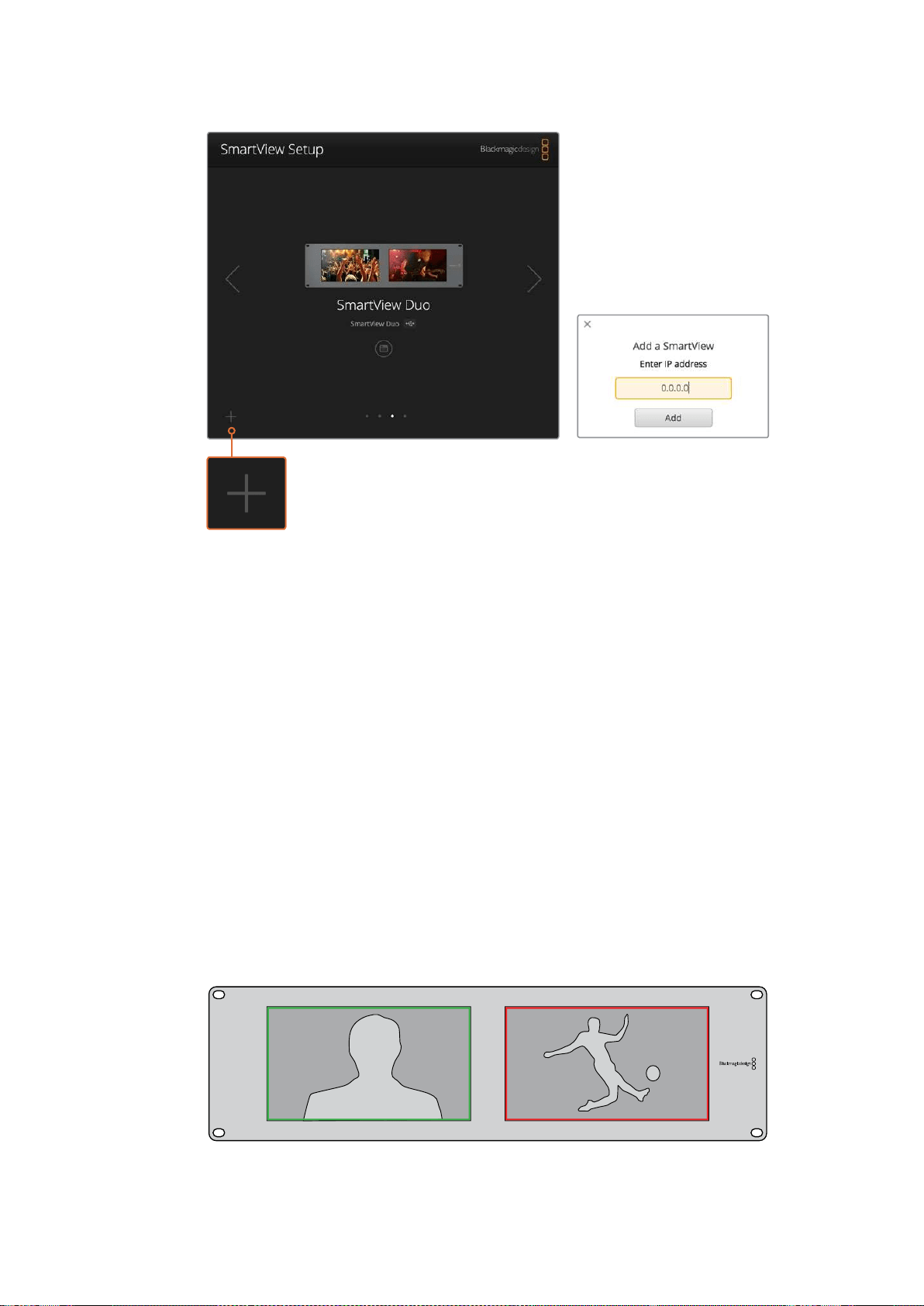
Bağlı olan monitörler listesine bir SmartView veya SmartScope monitörünü manuel
olarak ilave etmek için, ‘artı’ ikonunu tıklayarak monitörün IP adresini girebilirsiniz.
Tally Özelliğinin Kullanılması
Tally Port Pin Bağlantıları
SmartView veya SmartScope ünitelerinin tally portunu bağlamanıza gerek yoktur ve tally
özelliğini kullanmayı düşünmüyorsanız bu bölümü atlayabilirsiniz.
Her bir SmartView ve SmartScope ekranı, canlı yayında olma durumu, ön izleme ve kayıt
özellikleri gibi, bir video sinyalinin durumunu belirtmek üzere kullanılabilecek ve kırmızı, yeşil
veya mavi renklere sahip, bağımsız tally çerçeveleri içerir.
9-pin D-sub tally portu, switcher ve otomasyon sistemlerinden gelen kontak kapatma sinyallerini
kabul eder. Switcher veya otomasyon sisteminizle kullanılmak üzere, tally portu bağlantısı
hakkında bilgi için, ekteki tally pin bağlantıları şemasına bakınız.
9-pin D port bağlantı açıklaması ünitenin arkasında basılıdır. Bu açıklama, bağımsız monitörlerin
her birinde kırmızı, yeşil veya mavi tally çerçeveleri görüntülemeye yarayan kontak kapatma
konumlarını gösterir.
Yeşil ve kırmızı tally çerçeveleri gösteren SmartView Duo
407Tally Özelliğinin Kullanılması

İzleme Açısının Optimize Edilmesi
SmartView Duo, SmartView HD veya SmartScope monitörleri bir ekipman rack’inde yükseğe
monte edilecekse, en iyi izleme açısını sağlamak üzere, LCD’leri ters çevirmenizde yarar vardır.
LCD’ler tarafından çevrilme işlemi algılandığında, ekrandaki görüntüler otomatik olarak doğru
yöne dönecektir. Arka montaj düzeninden koruyucu çerçeveyi çıkartmak ve tekrar takmak için,
bir 02 büyüklüğünde pozidriv tornavida gerekecektir. Bu basit bir işlemdir ve arka montaj
düzeninin açılmasını gerektirmemektedir.
Aşağıdaki uygulama, Blackmagic Design logosunu koruyucu çerçeve üzerinde doğru yönde
tutarak üniteyi nasıl tersine çevirebileceğinizi açıklıyor. 02 boy numaralı pozidriv tornavida gerektirir.
1 Koruyucu çerçevenin üst, alt, sol ve sağ yüzlerindeki vidaları çıkartın.
SmartView Duo ve SmartScope Duo 4K üniteleri üzerinde 10 adet vida
bulunur ve SmartView HD üzerinde de 18 vida bulunur.
2 Resimde gösterildiği gibi, koruyucu çerçeveyi arka montaj düzeninden dışa
doğru çekin.
3 Arka montaj düzenini tersine çevirin.
4 Tersine çevrilmiş arka montaj düzenindeki koruyucu çerçeveyi geri yerleştirin.
5 Kasanın vidalarını yerine takın.
SmartView veya SmartScope üniteniz artık yüksek bir rack’e kurulmaya hazırdır. Bir rack’e
civatalandıktan sonra, SmartView ünitesi, yanlış kullanılabilecek veya gevşeyebilecek harici
düğmelere sahip olmadığından ve ayar gerektirmediğinden, çarpma anında dahi en iyi izleme
açısını görüntülemeye devam edecektir.
SmartView Duo ve SmartScope Duo 4K
Tally Pin Bağlantıları
Pin Fonksiyon
1 Monitör 1 Kırmızı
2 Monitör 1 Yeşil
3 Monitör 1 Mavi
4 Topraklama (Ground)
5 Topraklama (Ground)
6 Topraklama (Ground)
7 Monitör 2 Kırmızı
8 Monitör 2 Yeşil
9 Monitör 2 Mavi
SmartView HD ve SmartView 4K
Tally Pin Bağlantıları
Pin Fonksiyon
1 Kırmızı
2 Yeşil
3 Mavi
4 Topraklama (Ground)
5 4 3 2 1
9 8 7 6
SmartView Tally-Port
408
İzleme Açısının Optimize Edilmesi
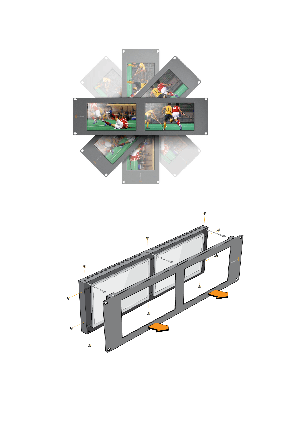

Yazılım Geliştirici Bilgileri
Blackmagic Design Donanımları Kullanılarak Özel Yazılımların Geliştirilmesi
Blackmagic SmartView Ethernet Protocol, yazılım geliştiricilerinin kendi geliştirdikleri özel yazılımlarla
Blackmagic SmartView ve Blackmagic SmartScope ünitelerini uzaktan kontrol etmelerini mümkün
kılar. Blackmagic SmartView Ethernet Protocol bir metin bazlı durum ve kontrol protokolüdür.
Ücretsiz SmartView Ethernet Protocol’ün İndirilmesi
Blackmagic SmartView Ethernet Protocol ücretsizdir. Bu SmartView & SmartScope kılavuzuna
dahil edilmiştir ve http://www.blackmagicdesign.com/support/ adresinden indirilebilir.
Blackmagic Design Yazılım Geliştiriciler Listesine Dahil Olmak
Blackmagic Yazılım Geliştiricileri e-posta listesi, Blackmagic Design tarafından kullanılan
teknolojilere ilişkin teknik sorular için tasarlanmıştır. Örnegin, QuickTime, Core Media, DirectShow,
codecs, APIs, SDKs, vs. Ücretsiz olan bu liste, geliştiricilerin başka geliştiricilerle fikirlerini ve
sorunlarını paylaşabileceği bir forumdur. Sunulan sorulara herhangi bir abone yanıt verebilir ve
uygun olduğu durumlarda, Blackmagic Design mühendisleri de yanıt verebilirler. E-posta listesine
abone olabileceğiniz link: http://lists.blackmagicdesign.com/mailman/listinfo/bmd-developer
Bazı durumlarda, internet alan adınızdan kurumunuzun video yazılımı geliştirdiği bariz şekilde
anlaşılmıyorsa, geliştirmekte olduğunuz yazılım hakkında kısa bir tanım talep edebiliriz. Bu
talebimizi lütfen yanlış anlamayınız çünkü, amacımız abonelik listemizi istenmeyen e-posta ve
virüslerden korumaktır. Aynı zamanda, kullanıcıların yazılım geliştirmekle alakası olmayan sorular
yöneltmelerini ve işçi bulma kurumlarının veya satıcıların, liste vasıtasıyla ürün reklamı
yapmalarını önlemeyi amaçlıyoruz. Bu liste, sadece yazılım geliştiricileri içindir.
Blackmagic Design Yazılım Geliştiricilerine Yardım Hizmetiyle İrtibat
Geliştiricilere ilişkin veya listeye bağlı sorularınız olduğunda da, bizimle
developer@blackmagicdesign.com adresinden irtibata geçebilirsiniz.
Blackmagic 2K Formatı – Genel Tanıtım
Blackmagic Design ürünleri, geleneksel HD-SDI videonun veri hızını ikiye katlayan 3G-SDI video
teknolojisini destekler. Sinema filmi iş akışlarını kolaylaştırmak amaçlı olarak, 3G-SDI teknoloji sayesinde
2K film desteğini de ilave etmenin faydalı olacağını düşündük. Blackmagic Design kurgu sistemlerinin
dünya çapındaki popülaritesi sayesinde, artık binlerce insan, sinema film iş akışlarından yararlanabilir.
Bu bilgiler, ürün geliştiricilerinin native 2K SDI ekipman geliştirmeleri için bilmeleri gereken her şeyi içerir.
Kuşkusuz ki, Blackmagic ürünlerinin hepsi güncellenebilmektedir. Bu nedenle, televizyon endüstrisi
alternatif bir SDI-bazlı film standardını benimsese bile, biz o standart için de destek ekleyebilmekteyiz.
410Yazılım Geliştirici Bilgileri

Kare Yapısı
Saniyede 23.98, 24 veya 25 kare hızlarında, Progressive Segmented Frame (PsF)
olarak aktarılmaktadır.
Aktif video 2048 piksel genişliğinde ve 1556 satır derinliğindedir.
Kare başına toplam satır sayısı : 1650
Satır başına düşen aktif sözcük sayısı 1535. Her kelime, dört adet veri akışının her biri
için 10-bit bir örnekten oluşmaktadır. Örneğin, toplam 40 bit olmak üzere. Blackmagic
2K Format - Data Stream Format başlıklı şemaya bakınız.
Toplam aktif satır sayısı: 1556
Her satırdaki toplam sözcük sayısı : 23.98/24Hz için 1875 ve 25Hz için 1800.
Kare başına alan sayısı: her biri 2, 825 satır
16-793 nolu (1. alan) ve 841-1618 nolu (2. alan) satırlarda bulunan aktif satır sayısı.
Aktarma Yapısı
SMPTE 372M Dual Link eşleştirmeyi ve SMPTE 372M’yi tek bir 3 Gb/sn link’e
eşleştirmeye yarayan SMPTE 425M-B desteğini baz alır.
Zamanlama referans sinyalleri, satır numarası ve satır CRC ekleme işlemi
yukarıdaki gibidir.
Aktif video esnasında, 10-bit Kırmızı, Yeşil ve Mavi veri; aşağıdaki sekansta iletilir.
Opsiyonel olan yardımcı veriler sanal arayüzün her ikisine de eklenir.
Mevcut durumda, sadece ses verisi dahil edilmiştir: HD ses ekleme (SMPTE S299M)
standardına uygun olarak ses veri paketleri ikinci veri akışında ve ses kontrol paketleri
ise birinci veri akışında aktarılır.
Data stream 1: Green_1, Green_2, Green_3, Green_5...Green_2047
Data stream 2: Blue_1, Blue_2, Green_4, Blue_5...Green_2048.
Data stream 3: Red_1, Blue_3, Blue_4, Red_5...Blue_2048.
Data stream 4: Red_2, Red_3, Red_4, Red_6...Red_2048.
Blackmagic 2K Format – Vertical Timing Reference
(DikeyZamanlama Referansı)
Bu grafik, Zamanlama Referans Sinyali (Timing Reference Signal) kodları için; satır numarası ve
Alan, Dikey ve Yatay bölüm bilgileri ile dikey zamanlama detaylarını gösterir.
Field 1
(1. alan)
Aktif
F 1 0 0 0 0 0 0 0 0 0 0 0
V 1 1 1 1 1 1 0 0 0 0 1 1
LINE #
(SATIR
NUMARASI)
1650 1 2 ... 14 15 16 ... 792 793 ... 825
Field 2
(2. alan)
Aktif
F 0 1 1 1 1 1 1 1 1 1 1 1
V 1 1 1 1 1 1 0 0 0 0 1 1
LINE #
(SATIR
NUMARASI)
825 826 827 ... 839 840 841 ... 1617 1618 ... 1650
411Yazılım Geliştirici Bilgileri
Blackmagic 2K Format – Data Stream Format
Bu grafik, yatay çizginin opsiyonel yardımcı veri bölümünün çevresindeki veri akışı formatlarını
gösterir. Aklınızda bulunsun ki, aktif piksellerin her biri üç örneklik yer kaplar.
Data Stream 1
G2041
G2042
G2043
G2045
G2046
G2047
EAV(3FFh)
EAV(000h)
EAV(000h)
EAV(XYZh)
LN0
LN1
CRC0
CRC1
ANC/Audio
Data
SAV(3FFh)
SAV(000h)
SAV(000h)
SAV(XYZh)
G1
G2
G3
G5
Data Stream 2
B2041
B2042
G2044
B2045
B2046
G2048
EAV(3FFh)
EAV(000h)
EAV(000h)
EAV(XYZh)
LN0
LN1
CRC0
CRC1
ANC/Audio
Data
SAV(3FFh)
SAV(000h)
SAV(000h)
SAV(XYZh)
B1
B2
G4
B5
Data Stream 3
R2041
B2043
B2044
R2045
B2047
B2048
EAV(3FFh)
EAV(000h)
EAV(000h)
EAV(XYZh)
LN0
LN1
CRC0
CRC1
040
…
040
SAV(3FFh)
SAV(000h)
SAV(000h)
SAV(XYZh)
R1
B3
B4
R5
Data Stream 4
R2042
R2043
R2044
R2046
R2047
R2048
EAV(3FFh)
EAV(000h)
EAV(000h)
EAV(XYZh)
LN0
LN1
CRC0
CRC1
200
…
200
SAV(3FFh)
SAV(000h)
SAV(000h)
SAV(XYZh)
R2
R3
R4
R6
Word#
23.98/24 PsF
1870
1871
1872
1873
1874
1875
1
2
3
4
5
6
7
8
9
…
335
336
337
338
339
340
341
342
343
Word#
25 PsF
1795
1796
1797
1798
1799
1800
1
2
3
4
5
6
7
8
9
…
260
261
262
263
264
265
266
267
268
412Yazılım Geliştirici Bilgileri

Blackmagic SmartView Ethernet Protocol v1.3
Özet
Blackmagic SmartView Ethernet Protocol, bir metin bazlı durum ve kontrol protokolüdür. Yapısal
olarak Videohub protokolüne çok benzemektedir ve bir SmartView ya da SmartScope cihazı
üzerindeki TCP port 9992’ye bağlanarak bu protokole erişim sağlanır.
Bağlantı kurulduğunda, SmartView veya SmartScope cihazı, cihazın eksiksiz bir dökümünü
gönderir. İlk dökümden sonra, durum değişiklikleri eşzamanlı olmadan gönderilir.
Cihaz, bilgileri bloklar halinde iletir ve bu blokların tanımlayıcı bir başlığı, devamında da iki nokta
üst üste bulunur. Bir blok birden fazla satırdan oluşabilir ve boş bir satır ile biter.
Gelecekteki protokol değişikliklerine karşı dayanıklı olabilmesi açısından, kullanıcılar izleyen boş
satıra kadar, tanımadıkları blokları dikkate almamalıdırlar. Tanınan bloklar kapsamında,
kullanıcılar tanımadıkları satırları dikkate almamalıdırlar.
Blackmagic SmartView Ethernet Protocol’ün 1.3 sürümü
SmartView 1.3 yazılımıyla piyasaya sunulmuştu.
Protokol Preamble (Başlama Eki)
SmartView Server (sunucusu) tarafından gönderilen ilk blok, her zaman için protokol
başlama ekidir.
PROTOCOL PREAMBLE:
↵
Version: 1.3
↵
↵
Sürüm (version) alanı protokol sürümünü belirtir. Protocol uyumlu bir şekilde değiştirildiğinde,
minor sürüm numarası güncellenecektir. Uyumlu olmayan değişiklikler yapıldığında, asıl sürüm
numarası güncellenecektir.
Cihaz Bilgileri
Bir sonraki blok, bağlı olan SmartView veya SmartScope cihazı hakkında genel bilgi içerir.
SMARTVIEW DEVICE:
↵
Model: SmartView Duo
↵
Hostname: stagefront.studio.example.com
↵
Name: StageFront
↵
Mo nitor s: 2
↵
Inverted: false
↵
↵
Bu örnek, iki adet LCD’si bulunan bir SmartView Duo cihazının çıktısını gösteriyor. INVERTED
uyarısı, LCD izleme açısının optimize edilmesi amacıyla, cihazın ters çevrilmiş bir şekilde
montajlanıp montajlanmadığını belirtir.
Legend
↵
carriage return
… and so on
413Yazılım Geliştirici Bilgileri

Ağ Yapılandırması
Bir sonraki blok TCP/IP ağ yapılandırmasını gösterir:
NETWORK:
↵
Dynamic IP: true
↵
Static address: 192.168.2.2
↵
St atic netm as k: 255.255.255.0
↵
St atic gatew ay: 192.168.2.1
↵
C u rr e nt ad d r e ss: 192.168.1.101
↵
C u rr e nt netm a sk: 255.255.255.0
↵
C u rr e nt g ate w ay: 192.168.1.1
↵
↵
Önünde CURRENT ibaresi beliren ağ ayarları, aktif olan TCP/IP ayarlarını gösterir ve salt okunur
modundadır. CURRENT ayarları, DYNAMIC IP uyarısına bağlı olarak, DHCP veya Static (Sabit)
yapılandırmayı yansıtır.
Ağ Ayarlarının Değiştirilmesi
Ağ, DHCP veya bir sabit yapılandırmanın herhangi birini kullanmak üzere yapılandırılabilir.
DHCP’yi etkinleştirmek için:
NETWORK:
↵
Dynamic IP: true
↵
↵
Sabit bir IP adresi oluşturmak için, tüm sabit parametreleri bildirin, dolayısıyla:
NETWORK:
↵
Dynamic IP: false
↵
Static address: 192.168.2.2
↵
St atic netm as k: 255.255.255.0
↵
St atic gatew ay: 192.168.2.1
↵
↵
Önünde CURRENT ibaresi bulunan tüm parametreler salt okunur moddadır ve sabit veya
dinamik ayarına bakmaksızın, aktif yapılandırmayı gösterir.
Cihazın adını veya ağ ayarlarından herhangi birini değiştirmek, IP bağlantısının düşmesine sebebiyet
verecektir. Cihaz ağ iletişimini yeniden başlatacaktır ve ağ üzerinde yeni adını ilan edecektir.
Monitör Ayarlarının Değiştirilmesi
Her bir monitör için görüntüleme ayarları ayrı ayrı belirlenir. Parametrelerden biri veya daha
fazlası aynı anda değiştirilebilir ve birden fazla ayar tek bir blok kapsamında sunulabilir.
Sayısal değerler için geçerli aralık 0 ila 255 arasıdır. CONTRAST ( kontrast) ve SATURATION
(doygunluk) özellikleri sıfır merkezlidir. Böylelikle normal değeri 127’dir, öyle ki görüntülenen
görüntü orijinaliyle aynıdır. Kanalların herhangi birinde 127’den daha yüksek olan bir değer,
kontrast veya doygunluğun artmasına sebep olur. Aynı şekilde, 127’den daha düşük bir değer
de bir artışa yol açacaktır.
Örneğin, parlaklığı %50’ye ayarlayarak görüntünün doygunluğunu Siyah & Beyaz’a
getirmek için:
MONITOR A:
↵
Brightness: 127
↵
Saturation: 0
↵
↵
414Yazılım Geliştirici Bilgileri

16:9’da SD Görüntüleme
Aşağıdaki komut, standart tanımlı video’nun 16:9’da görüntülenmesini sağlar:
MONITOR A:
↵
WidescreenSD: ON
↵
4:3’te SD Görüntüleme
Aşağıdaki komut, standart tanımlı video’nun 4:3’te görüntülenmesini sağlar:
MONITOR A:
↵
WidescreenSD: OFF
↵
Belirleme ve Tally Ayarları
‘Identify’ (Belirle) uyarısı geçicidir ve 15 saniyelik bir süre boyunca görüntünün tamamının
çevresinde beyaz bir çerçeve sergilenmesini sağlar. Bu süreden sonra, yeniden ayarlanır. Bu
özellik, içinde birden fazla ünitenin bulunduğu bir rack’e montajlandığı durumlarda, hali hazırda
hangi monitörün yapılandırıldığını belirlemeyi amaçlar. Bu özelliği etkinleştirmek için:
MONITOR A:
↵
Ide ntify: tr u e
↵
↵
Buna göre, IDENTIFY çerçevesi diğer bütün çerçeve ayarlarını geçici olarak geçersiz kılar.
BORDER (çerçeve) özelliği, yazılım bazlı Tally özelliğinin renkli çerçevelerini ana renklerden
birine ayarlamak için, pragmatik olarak kullanılabilir. RED (kırmızı), GREEN (yeşil), BLUE (mavi),
WHITE (beyaz) veya NONE (Hiçbiri). Bu ayar, cihazın kendi üzerindeki DB-9 girişinde, elektrikli
Tally sinyalleri tarafından geçersiz kılınabilir. Örneğin, yazılım bazlı Tally rengini yeşile
ayarlamak için:
MONITOR B:
↵
Border: green
↵
↵
Fiziksel bağlantısı olan tally, her zaman için yazılım bazlı olanını geçersiz kılacaktır. Eksiksiz
durum raporu her zaman, mevcut olan geçerli çerçeveyi gösterecektir.
SmartScope Ayarları
SmartScope Duo 4K’da her bir monitör farklı bir skop görüntülemek üzere ayarlanabilir. Belirli
skopları etkinleştirmek için gereken değerler aşağıdaki şekilde eşleştirilmiştir:
AudioDbfs
AudioDbvu
Histogram
ParadeRGB
ParadeYUV
Picture (Bu Video Monitor ile aynıdır)
Vector100
Vector75
WaveformLuma
MONITOR A:
↵
ScopeMode: Picture
↵
↵
Yukarıdaki örnekte, Monitör A, bir video monitörü olarak ayarlanmıştır.
415Yazılım Geliştirici Bilgileri

16:9’da SD Görüntüleme
Standart tanımlı videoyu 16:9 formatında görüntülemek üzere Video Monitor (video monitörü)
modunu ayarlamak için:
MONITOR A:
↵
ScopeMode: Picture
↵
WidescreenSD: ON
↵
4:3’te SD Görüntüleme
Standart tanımlı videoyu 4:3 formatında görüntülemek üzere Video Monitor (video monitörü)
modunu ayarlamak için:
MONITOR A:
↵
ScopeMode: Picture
↵
WidescreenSD: OFF
↵
SmartScope Duo 4K’nın monitörlerinden birini, ses göstergelerini görüntülemek üzere
ayarlarken, ayrıca hangi kanalların gösterilmesini istediğinizi de seçebilirsiniz. Ses kanallarının
seçiminde gerekli olan değerler, aşağıdaki şekilde eşleştirilmiştir:
0: 1 ve 2 numaralı Kanallar
1: 3 ve 4 numaralı Kanallar
2: 5 ve 6 numaralı Kanallar
3: 7 ve 8 numaralı Kanallar
4: 9 ve 10 numaralı Kanallar
5: 11 ve 12 numaralı Kanallar
6: 13 ve 14 numaralı Kanallar
7: 15 ve 16 numaralı Kanallar
MONITOR B:
↵
ScopeMode: AudioDbvu
↵
AudioChannel: 0
↵
↵
Yukarıdaki örnekte, Monitör B, Ses Göstergesini Dbvu modunda görüntülemek üzere ve 1 ile 2
numaralı kanallar da, faz göstergesini görüntülemek üzere seçilmiştir.
SmartView 4K için LUT’ların Seçilmesi
SmartView 4K’yı kullanarak bir 3D LUT seçmek için:
MONITOR A:
↵
LUT: 0 LUT 1
1 LUT 2
NONE DISABLE
↵
↵
416Yazılım Geliştirici Bilgileri

Yardım
Yardım İçin
Yardım almak için takip edeceğiniz dört adım vardır.
1 En güncel destek notları ve bilgileri için lütfen www.blackmagicdesign.com/tr/support
adresinden, Blackmagic Design destek merkezine bakınız.
2 Blackmagic Design satıcınızı arayın.
3 Yerel satış bayiniz, Blackmagic Design’in en son teknik güncellemelerine sahiptir
ve size anında yardım sunabilecektir. Ayrıca, satış bayinizin sunmuş olduğu destek
seçeneklerini de gözden geçirmenizi öneriyoruz çünkü, iş akışı gereksinimlerinize
bağlı olarak sizin için çeşitli destek düzenlemeleri yapabilirler.
4 Bir sonraki seçenek ise www.blackmagicdesign.com/tr/support adresinden erişim
sağlayacağınız, “send us an email’ (bize elektronik posta gönderin) butonunu
kullanarak, elektronik posta yoluyla bize sorularınızı iletmenizdir.
5 Bir Blackmagic Design destek ofisini arayın. Destek sayfasının altındaki “Find your
local support team” (yerel destek ekibinizi bulun) butonunu tıklayarak, size en yakın
olan ofisi bulabilirsiniz.
Sorununuza en kısa zamanda yanıt verebilmemiz açısından, teknik sorununuz ve sistem
özellikleri hakkında, lütfen bize mümkün olduğunca fazla bilgi sağlayınız.
417Yardım
Düzenleyici Bildirim ve Güvenlik Bilgileri
Düzenleyici Uyarıları
Avrupa Birliği genelinde elektrikli ve elektronik ekipman atıklarının bertaraf edilmesi.
Ürün üzerindeki sembol, bu ekipmanın başka atık malzemelerle bertaraf edilmemesi
şartını belirler. Atık ekipmanlarınızın bertaraf edilmesi için, geri dönüşümünü sağlamak
üzere belirlenmiş toplama noktasına teslim edilmeleri gerekmektedir. Atık
ekipmanlarınızın, bertaraf edilmek üzere ayrı olarak toplanması ve geri dönüşümü,
doğal kaynakların korunmasına yardımcı olacaktır ve insan sağlığını ve çevreyi
koruyucu bir şekilde geri dönüşümünü sağlayacaktır. Atık ekipmanlarınızı geri
dönüşüm için nereye teslim edebileceğiniz konusunda daha fazla bilgi için, lütfen yerel
belediyenizin geri dönüşüm şubesini ya da ürünü satın aldığınız satış bayisini arayınız.
Bu ekipman test edilmiş ve Federal İletişim Komisyonu (FCC) koşullarının 15. bölümü
doğrultusunda A Sınıfı dijital cihazların sınırlarıyla uyumlu olduğu tespit edilmiştir. İlgili
sınırlar, bu ekipman ticari bir ortamda çalıştırıldığında, zararlı müdahalelere karşı makul
koruma sağlamaları amacıyla tasarlanmıştır. Bu ekipman radyo frekans enerjisi üretir,
kullanır ve saçabilir ve talimatlar doğrultusunda kurulmadığı ve kullanılmadığı takdirde,
radyo komünikasyonlarına zararlı müdahaleye yol açabilir. Bu ürünün bir yerleşim
bölgesinde çalıştırılması, zararlı müdahaleye yol açabilir. Bu durumda, müdahalenin
düzeltilmesi için ilgili maliyeti, kullanıcının kendisi karşılamak zorunda kalacaktır.
Bu ürünün çalıştırılması aşağıdaki iki şarta bağlıdır:
1 Bu cihaz, zararlı müdahaleye sebebiyet vermemelidir.
2 Bu cihaz, istenmeyen işleme yol açan müdahaleler de dahil olmak üzere, maruz
kaldığı her türlü müdahaleyi kabul etmelidir.
Güvenlik Bilgileri
Bu ekipman, koruyucu topraklama bağlantısı olan bir şebeke prizine takılmalıdır.
Elektrik çarpması riskine karşı, bu ekipman damlayan veya sıçrayan suya maruz
bırakılmamalıdır.
Bu ekipman çevresel ısısı 40º C'ye kadar olan tropikal ortamlarda
kullanılmaya uygundur.
Ürünün çevresinde yeterli hava akışını sağlayan boşluk bulunduğuna ve
engellenmediğine dikkat ediniz.
Rafa montajlarken havalandırmanın, bitişik ekipmanlardan dolayı kısıtlanmadığından
emin olunuz.
Ürünün içinde, kullanıcı tarafından tamir edilebilecek hiç bir parça bulunmamaktadır.
Gerekli tamiratları yerel Blackmagic Design hizmet merkezine yönlendirin.
Deniz seviyesinden yüksekliğin 2000m'yi aşmadığı yerlerde kullanın.
Bu ürüne küçük ebatlı alıcı-verici (SFP) optik fiber modüller takılabilir. Yalnızca Lazer
1. sınıf optik SPF modüllerini kullanın.
Önerilen Blackmagic Design SFP modülleri:
3G-SDI: PL-4F20-311C
6G-SDI; PL-8F10-311C
418Düzenleyici Bildirim ve Güvenlik Bilgileri

Yetkili Servis Personeli için Uyarılar
Servis yapmadan önce her iki güç soketinden güç bağlantısını kesin!
Dikkat - Double Pole/Neutral Fusing (İki Kutuplu/Nötr Sigorta)
Bu ekipmanda bulunan güç kaynağının hem hat iletkeninde hem de nötr
iletkende elektrik sigortası bulunur ve Norveç’teki IT elektrik dağıtım
sistemine bağlantı için uygundur.
Garanti
12 Ay Sınırlı Garanti
Blackmagic Design şirketi, bu ürünün satın alındığı tarihten itibaren malzeme ve işçilik bakımından
12 ay boyunca kusursuz ve arızasız olacağını garanti eder. Üründe bu garanti süresi içinde bir arıza
ve kusur söz konusu olursa Blackmagic Design, kendi seçimi doğrultusunda, ya arızalı ürünü parça
ve işçilik bedeli talep etmeksizin tamir edecektir ya da arızalı ürünü, yenisiyle değiştirecektir.
Bu garanti kapsamı altında hizmetten yararlanmak için müşterilerimiz, Blackmagic Design'ı arızaya
ilişkin garanti süresi sona ermeden bilgilendirmelidir ve söz konusu hizmetin sağlanması için uygun
düzenlemeleri yapmalıdır. Blackmagic Design tarafından özel belirlenmiş ve yetkilendirilmiş bir hizmet
merkezine, arızalı ürünün ambalajlanarak sevkiyatı, Müşterilerimizin sorumluluğudur ve sevkiyat
ücretleri peşin ödenmiş olmalıdır. Herhangi bir sebepten dolayı bize iade edilen ürünlerin; tüm nakliye,
sigorta, yasal bedel, vergi ve diğer tüm masrafların ödenmesi müşterinin sorumluluğu altındadır.
Bu garanti; yanlış kullanım ya da yanlış veya kusurlu tamir ve bakımdan kaynaklanan herhangi bir
arızayı, bozukluğu ya da hasarı kapsamaz. Blackmagic Design burada açıklanan durumlarda, bu
garanti kapsamında hizmet sağlamak zorunda değildir: a) Blackmagic Design temsilcileri haricindeki
başka personelin ürünü kurma, tamir etme ya da bakımını yapma girişimlerinden kaynaklanan
hasarın tamir edilmesi, b) uygun olmayan kullanım veya uyumlu olmayan ekipmanlara bağlanılmasından
kaynaklanan hasarın tamir edilmesi, c) Blackmagic Design parçaları ya da malzemesi olmayan
ürünlerin kullanımından kaynaklanan hasarın ya da arızanın tamir edilmesi ya da d) Modifiye veya
başka ürünlerle entegre edilmiş bir ürünün; söz konusu modifikasyon ya da entegrasyonun gereken
tamiratın süresini uzattığı ya da ürün bakımını zorlaştırdığı durumlarda, tamir edilmesi. BU GARANTİ,
BLACKMAGIC DESIGN TARAFINDAN VERİLMİŞTİR VE AÇIK YA DA ZIMNİ, HERHANGİ BİR
GARANTİNİN YERİNİ TUTAR. BLACKMAGIC DESIGN VE SATICILARI, ZIMNİ TİCARİ UYGUNLUK
GARANTİSİNİ YA DA ÖZEL BİR AMACA UYGUNLUK GARANTİSİNİ KABUL ETMEZ. KUSURLU BİR
ÜRÜNÜN TAMİRİ VEYA DEĞİŞTİRİLMESİ, BLACKMAGIC DESIGN’İN MÜŞTERİLERİNE SUNDUĞU
TAM VE MÜNHASIR ÇÖZÜMDÜR. BLACKMAGIC DESIGN YA DA SATICILARININ OLABİLECEK
HASARLAR HAKKINDA ÖNCEDEN BİLGİSİ OLMASINI GÖZETMEKSİZİN, ÜRÜNDE DOLAYLI, ÖZEL,
TESADÜFİ YA DA NETİCE OLARAK ORTAYA ÇIKAN HERHANGİ BİR HASAR İÇİN, BLACKMAGIC
DESIGN SORUMLU DEĞİLDİR. BLACKMAGIC DESIGN, MÜŞTERİLER TARAFINDAN EKİPMANIN
YASAL OLMAYAN HERHANGİ BİR KULLANIMINDAN SORUMLU DEĞİLDİR. BLACKMAGIC DESIGN,
BU ÜRÜNÜN KULLANIMINDAN KAYNAKLANAN HERHANGİ BİR HASARDAN SORUMLU DEĞİLDİR.
BU ÜRÜNÜN ÇALIŞTIRILMASINDAN DOĞAN RİSK, KULLANICININ KENDİSİNE AİTTİR.
© Telif Hakkı Saklıdır 2018 Blackmagic Design. Tüm Hakları Saklıdır. ‘Blackmagic Design’, ‘DeckLink’, ‘HDLink’, ‘Workgroup
Videohub’, ‘Multibridge Pro’, ‘Multibridge Extreme’, ‘Intensity’ ve ‘Leading the creative video revolution’, ABD ve diğer ülkelerde
tescil edilmiş ticari markalardır. Diğer tüm şirket ve ürün isimleri bağlantılı oldukları ilgili şirketler/firmaların ticari markaları olabilir.
419Garanti
