Loading ...
Loading ...
Loading ...
Testing Procedures
7
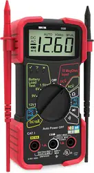
1. Plug the RED test lead
into the "Ω" jack of the
multimeter; plug the
BLACK test lead into the
"COM" jack.
2. Set the meter’s Function/
Range Selector Switch to
the "Ω" range function (see
Controls and Indicators,
Item 3).
NOTE: To obtain accurate readings, disconnect at least
one side of the item under test from the circuit or circuit
board before measuring resistance.
3. Place the RED test lead onto one side of the item
being tested and the BLACK test lead onto the other
side of the item. (Polarity does not matter when
checking resistance).
4. Read the results on the display.
C. DIODE TEST
WARNING
To avoid electrical shock and/or damage to the
multimeter, ensure the power is removed from the
circuit before any DIODE testing procedure is
conducted. Test diodes on de-energized (dead)
circuits only, never on live circuits.
NOTE: A diode is a semiconductor device that lets current
flow in one direction only. If the diode to be tested is part of
a circuit (with other electronic components), you must
isolate it from the other components by disconnecting at
least one side of it from the circuit before testing. A good
diode will show a low voltage drop across its junction (0.5-
0.8 volts for a silicon diode or about 0.3V for a germanium
diode) when the leads are connected in one polarity and a
very high resistance (or open circuit) when the leads are
reversed (connected in the opposite polarity).
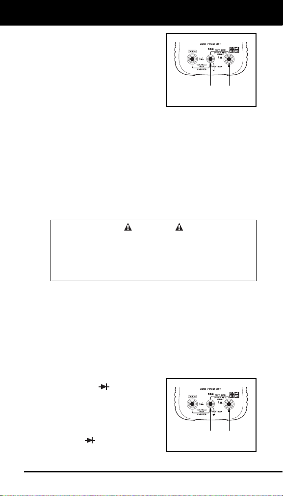
1. Plug the RED test lead
into the
jack of the
multimeter; plug the
BLACK test lead into the
"COM" jack.
2. Set the meter’s Function/
Range Selector Switch to
the
position (see
Controls and Indicators,
Item 5).
BLACK
LEAD
RED
LEAD
BLACK
LEAD
RED
LEAD
Loading ...
Loading ...
Loading ...