Loading ...
Loading ...
Loading ...
Testing Procedures
8
3. Place the RED test lead onto one side of the diode
being tested and the BLACK test lead onto the other
side.
4. Read the results on the display.
5. Reverse the test leads and again read the results on
the display. Compare the two readings. One reading
should indicate a voltage drop value; the other reading
should indicate an overrange (OL) condition. See note
above.
D. CONTINUITY TEST
WARNING
To avoid electric shock, shut off the power to the
test article before testing it for continuity.
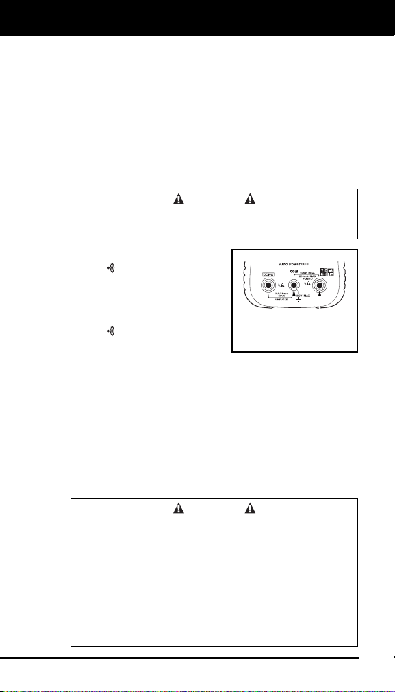
1. Plug the RED test lead into
the
jack of the multimeter;
plug the BLACK test lead
into the "COM" jack.
2. Set the meter’s Function/
Range Selector Switch to
the
position (see Controls
and Indicators, Item 6).
3. Place the RED Test Lead to one end of the wire or device
being tested for continuity and the BLACK Test Lead to
the opposite end.
4. Listen to the sound of the beeper and confirm the results
by reading the display.
NOTE: The beeper will sound only if the continuity of the
item under test (resistance between the two test leads)
measures less than 120 ohms.
E. AC/DC CURRENT MEASUREMENT (AMPS)
WARNING
To prevent electrical shock when performing current
measurements, follow all steps as indicated below
DO NOT skip any steps or take any short cuts.
The DC10A range is not fused. To avoid current
hazard and/or damage to the tester, DO NOT try to
take measurements on circuits that have more than
10 amps. DO NOT take more than 10 seconds to
take the reading. A waiting period of AT LEAST 15
MINUTES is necessary between every 15 second
testing period.
BLACK
LEAD
RED
LEAD
Loading ...
Loading ...
Loading ...