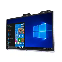

PN-CD701
LCD MONITOR
OPERATION MANUAL

IMPORTANT:
To aid reporting in case of loss or theft, please record the
product’s model and serial numbers in the space provided.
The numbers are located in the rear of the product.
Model No.:
Serial No.:
U.S.A. ONLY
3
E
IMPORTANT INFORMATION
WARNING: TO REDUCE THE RISK OF FIRE OR ELECTRIC SHOCK, DO NOT EXPOSE THIS PRODUCT
TO RAIN OR MOISTURE.
The lightning flash with arrowhead symbol, within
a triangle, is intended to alert the user to the
presence of uninsulated “dangerous voltage”
within the product’s enclosure that may be of
sufficient magnitude to constitute a risk of electric
shock to persons.
The exclamation point within a triangle is
intended to alert the user to the presence of
important operating and maintenance (servicing)
instructions in the literature accompanying the
product.
WARNING:
FCC Regulations state that any unauthorized changes or modifications to this equipment not expressly approved by the
manufacturer could void the user’s authority to operate this equipment.
NOTE:
This equipment has been tested and found to comply with the limits for a Class A digital device, pursuant to Part 15 of the
FCC Rules. These limits are designed to provide reasonable protection against harmful interference when the equipment
is operated in a commercial environment. This equipment generates, uses, and can radiate radio frequency energy and, if
not installed and used in accordance with the instruction manual, may cause harmful interference to radio communications.
Operation of this equipment in a residential area is likely to cause harmful interference in which case the user will be required
to correct the interference at his own expense.
This product utilizes a CR coin Lithium battery which contains a Perchlorate material.
Special handling for this material may apply,
California residents, See www.dtsc.ca.gov/hazardouswaste/perchlorate/
Others, consult local environmental officers.
U.S.A. ONLY
To maintain compliance with EMC regulations, use shielded cables to connect to the following terminals:
HDMI input terminal, USB input/output terminals and audio output terminal.
CAUTION: TO REDUCE THE RISK OF ELECTRIC
SHOCK, DO NOT REMOVE COVER.
NO USER-SERVICEABLE PARTS
INSIDE.
REFER SERVICING TO QUALIFIED
SERVICE PERSONNEL.
CAUTION
RISK OF ELECTRIC
SHOCK
DO NOT OPEN

4
E
Thank you for your purchase of a SHARP LCD product. To ensure safety and many years of trouble-free operation of your
product, please read the Safety Precautions carefully before using this product.
SAFETY PRECAUTIONS
Electricity is used to perform many useful functions, but it can also cause personal injuries and property damage if improperly
handled. This product has been engineered and manufactured with the highest priority on safety. However, improper use can
result in electric shock and/or fire. In order to prevent potential danger, please observe the following instructions when installing,
operating and cleaning the product. To ensure your safety and prolong the service life of your LCD product, please read the
following precautions carefully before using the product.
1. Read instructions — All operating instructions must be read and understood before the product is operated.
2. Keep this manual in a safe place — These safety and operating instructions must be kept in a safe place for future
reference.
3. Observe warnings — All warnings on the product and in the instructions must be observed closely.
4. Follow instructions — All operating instructions must be followed.
5. Cleaning — Unplug the power cord from the power outlet before cleaning the product. Use a dry cloth to clean the product.
Do not use liquid cleaners or aerosol cleaners. Do not use dirty cloths. Doing so may damage the product.
6. Attachments — Do not use attachments not recommended by the manufacturer. Use of inadequate attachments can result
in accidents.
7. Water and moisture — Do not use the product near water. Do not install the product in a place where water may splash onto
it. Be careful of equipment which drains water such as an air-conditioner.
8. Ventilation — The vents and other openings in the cabinet are designed for ventilation.
Do not cover or block these vents and openings since insufficient ventilation can cause overheating and/or shorten the life
of the product. Do not place the product on a sofa, rug or other similar surface, since they can block ventilation openings.
Do not place the product in an enclosed place such as a bookcase or rack, unless proper ventilation is provided or the
manufacturer’s instructions are followed.
9. Power cord protection — The power cords must be routed properly to prevent people from stepping on them or objects from
resting on them.
10. The screen used in this product is made of glass. Therefore, it can break when the product is dropped or applied with
impact. Be careful not to be injured by broken glass pieces in case the screen breaks.
11. Overloading — Do not overload power outlets or extension cords. Overloading can cause fire or electric shock.
12. Entering of objects and liquids — Never insert an object into the product through vents or openings. High voltage flows in
the product, and inserting an object can cause electric shock and/or short internal parts.
For the same reason, do not spill water or liquid on the product.
13. Servicing — Do not attempt to service the product yourself. Removing covers can expose you to high voltage and other
dangerous conditions. Request a qualified service person to perform servicing.
14. Repair — If any of the following conditions occurs, unplug the power cord from the power outlet, and request a qualified
service person to perform repairs.
a. When the power cord or plug is damaged.
b. When a liquid was spilled on the product or when objects have fallen into the product.
c. When the product has been exposed to rain or water.
d. When the product does not operate properly as described in the operating instructions.
Do not touch the controls other than those described in the operating instructions. Improper adjustment of controls
not described in the instructions can cause damage, which often requires extensive adjustment work by a qualified
technician.
e. When the product has been dropped or damaged.
f. When the product displays an abnormal condition. Any noticeable abnormality in the product indicates that the product
needs servicing.
15. Replacement parts — In case the product needs replacement parts, make sure that the service person uses replacement
parts specified by the manufacturer, or those with the same characteristics and performance as the original parts. Use of
unauthorized parts can result in fire, electric shock and/or other danger.
16. Safety checks — Upon completion of service or repair work, request the service technician to perform safety checks to
ensure that the product is in proper operating condition.
17. Wall mounting — When mounting the product on a wall, be sure to install the product according to the method
recommended by the manufacturer.
18. Heat sources — Keep the product away from heat sources such as radiators, heaters, stoves and other heat-generating
products (including amplifiers).
DEAR SHARP CUSTOMER
5
E
SAFETY PRECAUTIONS (Continued)
19. Batteries — Incorrect use of batteries may cause the batteries to burst or ignite. A leaky battery may corrode the equipment,
dirty your hands or spoil your clothing. In order to avoid these problems, make sure to observe the precautions below:
•Usethespecifiedbatteriesonly.
•Installthebatterieswithdueattentiontotheplus(+)andminus(-)sidesofthebatteriesaccordingtotheinstructionsinthe
compartment.
•Donotmixoldandnewbatteries.
•Donotmixbatteriesofdifferenttypes.Voltagespecificationsofbatteriesofthesameshapemayvary.
•Replaceanexhaustedbatterywithanewonepromptly.
•Ifyouwillnotusetheremotecontrolforalongtime,removethebatteries.
•Ifleakedbatteryfluidgetsonyourskinorclothing,rinseimmediatelyandthoroughly.Ifitgetsintoyoureye,batheyour
eye well rather than rubbing and seek medical treatment immediately. Leaked battery fluid that gets into your eye or your
clothing may cause a skin irritation or damage your eye.
20. Usage of the monitor must not be accompanied by fatal risks or dangers that, could lead directly to death, personal injury,
severe physical damage or other loss, including nuclear reaction control in nuclear facility, medical life support system, and
missile launch control in a weapon system.
21. Do not stay in contact with the parts of the product that become hot for long periods of time. Doing so may result in
low-temperature burns.
22. Do not modify this product.
WARNING:
This is a Class A product. In a domestic environment this product may cause radio interference in which case the user may
be required to take adequate measures.
An apparatus with CLASS I construction shall be connected to a MAIN socket outlet with a protective earthing connection.
STABILITY HAZARD
If a monitor is not positioned in a sufficiently stable location, it can be potentially hazardous due to falling. Many injuries,
particularly to children, can be avoided by taking simple precautions such as:
•Usingfixingdeviceslikewallmountbracketsrecommendedbythemanufacturer.
•Onlyusingfurniturethatcansafelysupportthemonitor.
•Ensuringthemonitorisnotoverhangingtheedgeofthesupportingfurniture.
•Notplacingthemonitorontallfurniture(forexample,cupboardsorbookcases)withoutanchoringboththefurnitureandthe
monitor to a suitable support.
•Notstandingthemonitorsonclothorothermaterialsplacedbetweenthemonitorandsupportingfurniture.
•Educatingchildrenaboutthedangersofclimbingonfurnituretoreachthemonitororitscontrols.
•Thisequipmentisnotsuitableforuseinlocationswherechildrenarelikelytobepresentunsupervised.
Especially for child safety
- Don’t allow children to climb on or play with the monitor.
- Don’t place the monitor on furniture that can easily be used as steps, such as a chest of drawers.
- Remember that children can become excited while watching a program, especially on a “larger than life” monitor. Care
should be taken to place or install the monitor where it cannot be pushed, pulled over, or knocked down.
- Care should be taken to route all cords and cables connected to the monitor so that they cannot be pulled or grabbed by
curious children.

6
E
-
The TFT color LCD panel used in this monitor is made with
the application of high precision technology. However, there
may be minute points on the screen where pixels never light
or are permanently lit. Also, if the screen is viewed from an
acute angle there may be uneven colors or brightness. Please
note that these are not malfunctions but common phenomena
of LCDs and will not affect the performance of the monitor.
- Do not display a still picture for a long period, as this could
cause a residual image.
- Never rub or tap the monitor with hard objects.
- Please understand that SHARP CORPORATION bears no
responsibility for errors made during use by the customer or
a third party, nor for any other malfunctions or damage to this
product arising during use, except where indemnity liability is
recognized under law.
- This monitor and its accessories may be upgraded without
advance notice.
-
Do not use the monitor where there is a lot of dust, where humidity
is high, or where the monitor may come into contact with oil or
steam. Do not use in an environment where there are corrosive
gases (sulfur dioxide, hydrogen sulfide, nitrogen dioxide, chlorine,
ammonia, ozone, etc.). As this could lead to fire.
-
Ensure that the monitor does not come into contact with water
or other fluids. Ensure that no objects such as paper clips or
pins enter the monitor as this could lead to fire or electric shock.
- Do not place the monitor on top of unstable objects or in
unsafe places. Do not allow the monitor to receive strong
shocks or to strongly vibrate. Causing the monitor to fall or
topple over may damage it.
- Do not use the monitor near heating equipment or in places
where there is likelihood of high temperature, as this may
lead to generation of excessive heat and outbreak of fire.
- Do not use the monitor in places where it may be exposed to
direct sunlight. Risk of cabinet deformation and failure if the
monitor is used in direct sunlight.
- Images cannot be rotated on this monitor.
When using in portrait orientation, you will need to prepare
appropriately orientated content in advance.
- The power outlet shall be installed near the equipment and
shall be easily accessible.
- Please be sure to constantly remove dust and garbage that
has attached to the ventilation opening. If dust collects in the
ventilation opening or the inside of the monitor, it may lead to
excessive heat, outbreak of fire, or malfunction.
Please request a cleaning of the inside of the monitor from
an authorized SHARP servicing dealer or service center.
- Do not touch the screen when the monitor power is turned
on, it will lead to a malfunction. When this occurs, turn the
monitor power off and then on.
- Do not operate the screen with a hard or pointed object such
as a fingernail or pencil.
- Depending on the application used, the touch pen may not
function.
- If another USB device is connected to the computer to which
the touch panel is connected, do not operate the USB device
during touch panel input. Input may not take place correctly.
- Do not allow a cable to come near the screen. This may
cause the touch panel to malfunction.
The Power Cord
- Use only the power cord supplied with the monitor.
- Do not damage the power cord nor place heavy objects on
it, stretch it or over bend it. Also, do not add extension cords.
Damage to the cord may result in fire or electric shock.
- Do not use the power cord with a power tap.
Adding an extension cord may lead to fire as a result of
overheating.
- Do not remove or insert the power plug with wet hands. Doing
so could result in electric shock.
- Unplug the power cord if it is not used for a long time.
- Do not attempt to repair the power cord if it is broken
or malfunctioning. Refer the servicing to the service
representative.
Manual Scope
- Microsoft and Windows are either registered trademarks or
trademarks of Microsoft Corporation in the United States
and/or other countries.
- Apple, Mac and macOS are trademarks of Apple Inc.,
registered in the U.S. and other countries.
- Google, Android and Chrome OS are trademarks or
registered trademarks of Google LLC.
- The terms HDMI, HDMI High-Definition Multimedia Interface,
and the HDMI Logo are trademarks or registered trademarks
of HDMI Licensing Administrator, Inc.
- DisplayPort is a registered trademark of Video Electronics
Standards Association.
- Intel, Celeron, and Intel Core are trademarks or registered
trademarks of Intel Corporation or its subsidiaries in the
U.S.A. and other countries.
- RoomView, Crestron RoomView and Crestron Connected
are either trademarks or registered trademarks of Crestron
Electronics, Inc. in the United States and/or other countries.
- VESA is either registered trademark or trademark of Video
Electronics Standards Association in the United States and/
or other countries.
- Bluetooth is a registered trademark of Bluetooth SIG, Inc.
- All other brand and product names are trademarks or
registered trademarks of their respective holders.
- Language of OSD menu used in this manual is English by
way of example.
- Illustrations in this manual may not exactly represent the
actual product or display.
LED Backlight
● TheLEDbacklightinthisproducthasalimitedlifetime.
* If the screen gets dark or does not turn on, it may be
necessary to replace the LED backlight.
* This LED backlight is exclusive to this product and must
be replaced by an authorized SHARP servicing dealer
or service center. Please contact an authorized SHARP
servicing dealer or service center for assistance.
TIPS AND SAFETY INSTRUCTIONS

7
E
MOUNTING PRECAUTIONS
• Thisproductisforuseindoors.
• AmountingbracketcompliantwithVESAspecificationsis
required.
• Sincethemonitorisheavy,consultyourdealerbefore
installing, removing or moving the monitor.
• Mountingthemonitoronthewallrequiresspecialexpertise
and the work must be performed by an authorized SHARP
dealer. You should never attempt to perform any of this
work yourself. Our company will bear no responsibility
for accidents or injuries caused by improper mounting or
mishandling.
• Usethemonitorwiththesurfaceperpendiculartoalevel
surface.
• Whenmovingthismonitor,besuretoholditwiththe
handles, the unit sides or the unit top. Do not grasp the
screen, unit corner or speaker. This may cause product
damage, failure, or injury.
• Thismonitorshouldbeusedatanambienttemperature
between 41°F (5°C) and 95°F (35°C).
• Becarefulofhightemperaturesinthesurroundingarea.
If it is difficult to provide sufficient space for any reason
such as the installation of the monitor inside a housing, or
if the ambient temperature may be outside of the range
of 41°F (5°C) to 95°F (35°C), install a fan or take other
measures to keep the ambient temperature within the
required range.
• Temperatureconditionmaychangewhenusingthemonitor
together with the optional equipments recommended by
SHARP. In such cases, please check the temperature
condition specified by the optional equipments.
• Donotblockanyventilationopenings.Ifthetemperature
inside the monitor rises, this could lead to a malfunction.
• Donotplacethemonitoronadevicewhichgeneratesheat.

8
E
Contents
IMPORTANT INFORMATION ............................................ 3
DEAR SHARP CUSTOMER ..............................................4
SAFETY PRECAUTIONS ..................................................4
TIPS AND SAFETY INSTRUCTIONS ...............................6
MOUNTING PRECAUTIONS ............................................7
Supplied Components ..................................................... 9
System Requirements .....................................................9
Part Names .....................................................................10
Connecting Peripheral Equipment ...............................12
Mounting an IoT sensor hub ......................................... 14
Mounting a camera ........................................................14
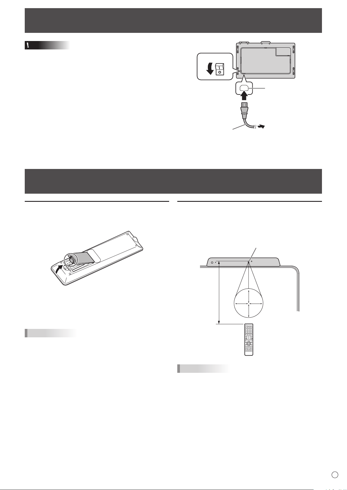
Connecting the Power Cord .........................................15
Preparing the Remote Control Unit .............................. 15
Installing the batteries ................................................15
Remote control operation range .................................15
Turning Power On/Off .................................................... 16
Turning on the main power.........................................16
Turning power on .......................................................16
Turning power off .......................................................16
Touch Pen ....................................................................... 17
Touch action ................................................................... 18
Touch action ...............................................................18
Other functions ...........................................................20
Cautionary points .......................................................20
Basic Operation .............................................................21
Button Operation ........................................................21
IoT accessories Operation .........................................21
Using the remote control unit (option) ........................22
Menu Items .....................................................................23
Displaying the menu ...................................................23
Main function in Action Panel .....................................25
Network ........................................................................... 29
Troubleshooting .............................................................30
Specifications ................................................................31
Intellectual Property Rights and Other Matters ..........35
Mounting Precautions
(For SHARP dealers and service engineers) ............... 36
9
E
Supplied Components
If any components are missing, please contact your dealer.
Liquid Crystal Display Monitor: 1
Power cord: 1
HDMI cable: 1
USB Type C cable (26.2 feet [8 m]): 1
USB Type C extend cable: 1
CD-ROM: 1
Setup Manual: 1
Touch pen: 1
* The remote control unit is supplied with the PN-ZR02 (optional).
(Remote control sensor box is not used.)
* For environmental protection!
Do not dispose of batteries in household waste. Follow the disposal instructions for your area.
About USB Type C extend cable
• ConnecttheUSBTypeCextendcable(supplied)betweentheUSBTypeCcable(supplied)andtheexternaldevice.
When connecting/disconnecting to the external device, plug/unplug the USB Type C extend cable to prevent damage to the
USB Type C cable.
USB A to B cable (for touch back): 1
Cable clamp: 1
Camera: 1
Knurled screw (M3): 2
USB A to B cable (for camera): 1
S/PDIF cable: 1
3.5 mm mini jack to USB A cable: 1
System Requirements
Hardware Must have a USB 2.0 compliant port.
Operating system
Windows 8.1 (32-bit or 64-bit version), Windows 10 (32-bit or 64-bit version)
(Windows 10 recommended.)
macOS v10.12, v10.13
Google Chrome OS Version 75 or later
The USB port varies depending on the terminal connected to the computer.
USB Type C 1 input terminal USB Type C 1 input terminal
USB Type C 2 input terminal USB Type C 2 input terminal
HDMI input terminal USB Type B input terminal for touch back
IoT sensor hub: 1
Micro USB cable (for IoT sensor hub): 1
Knurled screw (M3): 2
IoT sensor hub screw (M3): 2
IoT sensor hub mounting brackets (L/R):
x1 each
10
E
Part Names
n
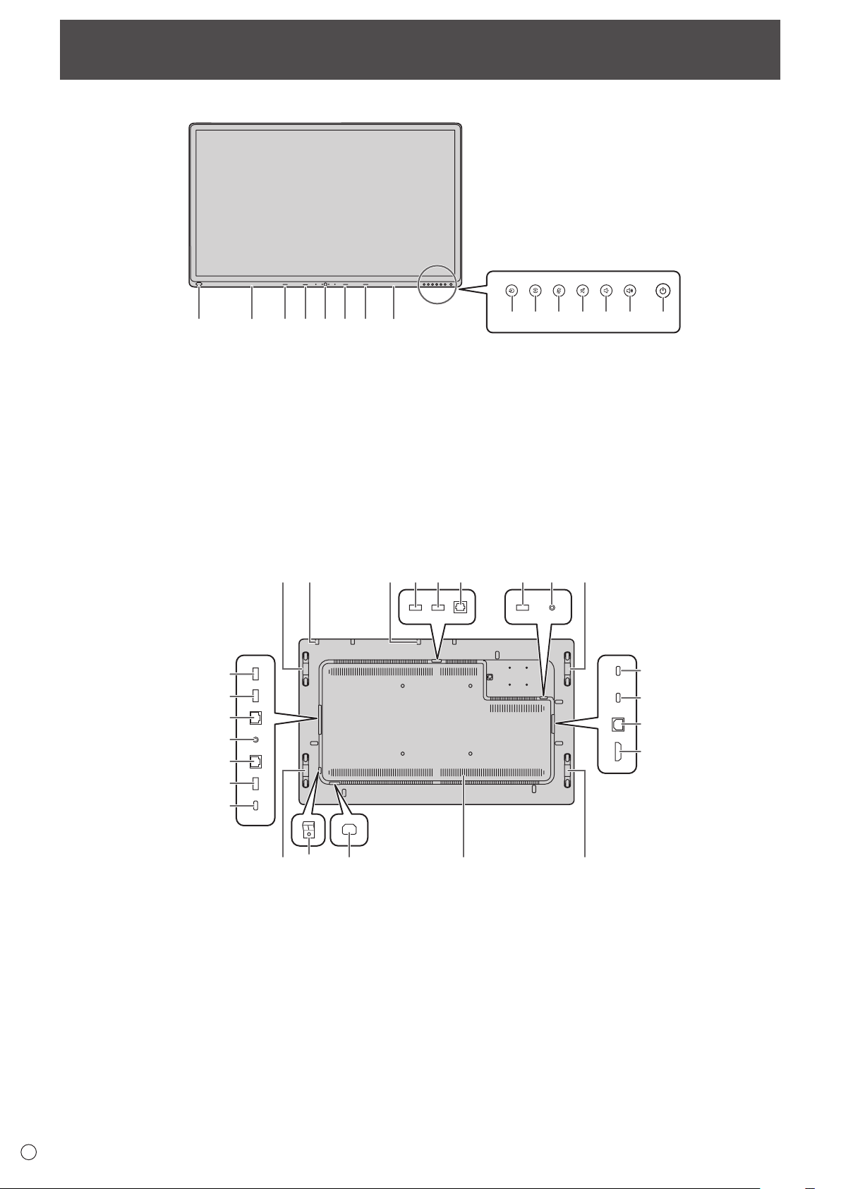
Front view
3 4 5 6 71
2 2
9 10 11 12 138 14
n
Rear view
17 1520 1819
21
22
23
24
34
33
32
31
30
29
28
27 26 25 15
15 35 36
15
16
1. USB port for external source (USB 3.0 compliant) (See
page 13.)
2. Pen Tray (See page 17.)
3. LED indicator for USB Type C 1 source
4. LED indicator for USB Type C 2 source
5. Windows button
6. LED indicator for HDMI
7. LED indicator for Wireless LAN
15. Handles
16. 3.5 mm jack for service (See page 13.)
17. USB port for camera 2 (See page 13.)
18. Optical audio input terminal (S/PDIF) (See page 13.)
19. USB port for camera 1 (See page 13.)
20. USB port for external source (USB 3.0 compliant) (See page 13.)
21. USB Type C 1 input terminal (See page 12.)
22. USB Type C 2 input terminal (See page 12.)
23. USB Type B input terminal for touch back (pair with HDMI input terminal) (See page 12.)
8. INPUT button (See page 21.)
9. MENU button (See page 21.)
10. MIC MUTE button (See page 21.)
11. MUTE button (See page 21.)
12. VOLUME DOWN button (See page 21.)
13. VOLUME UP button (See page 21.)
14. POWER button (See page 16.)
11
E
Part Names
n
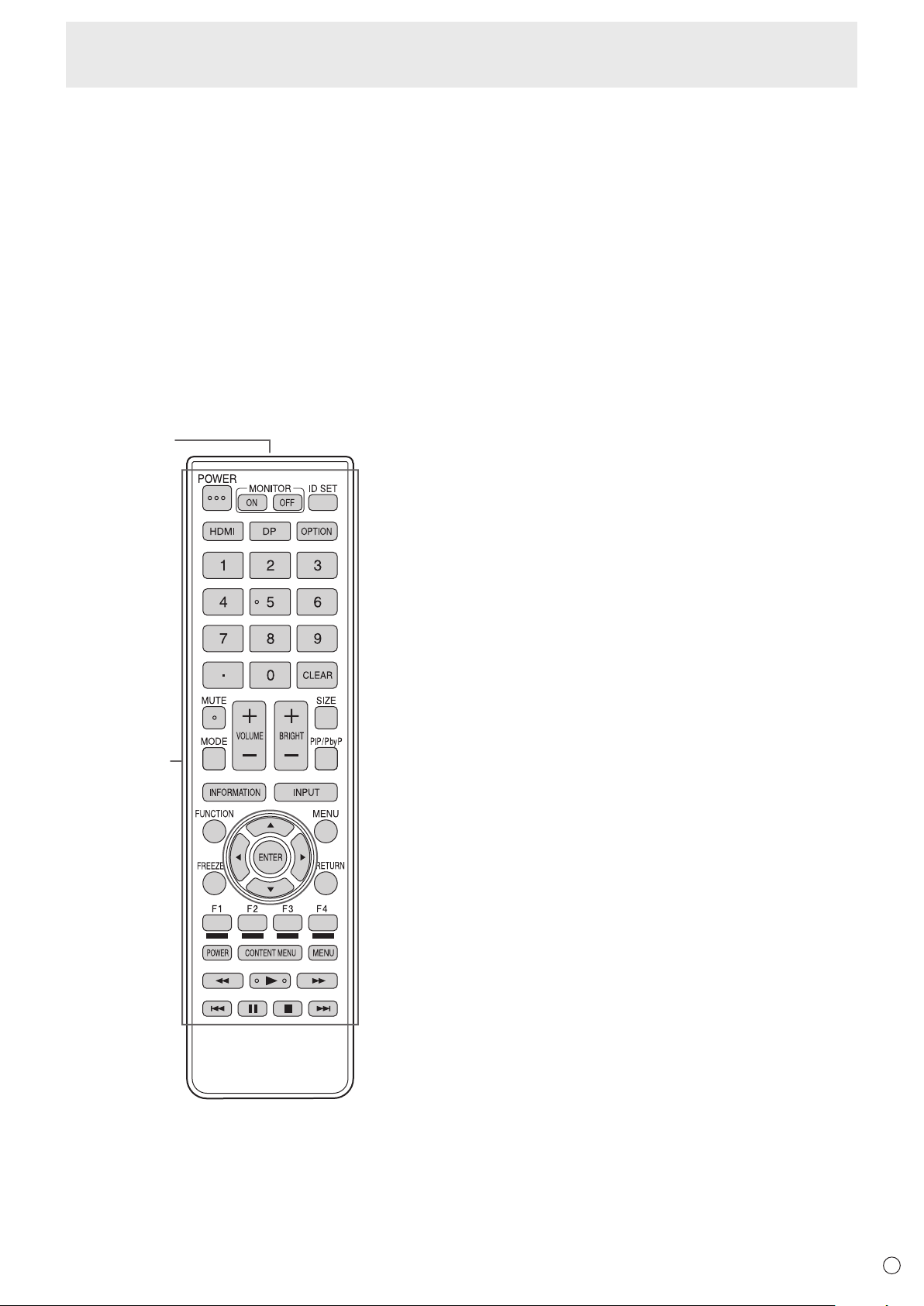
Remote control unit
(Supplied with the PN-ZR02 (optional))
1
2
1. Signal transmitter
2. Operation buttons (See page 22.)
24. HDMI input terminal (See page 12.)
25. Vents
26. AC input terminal (See page 15.)
27. Main power switch (See page 16.)
28. USB Type C output terminal (See page 13.)
29. USB port for storage expansion (USB 3.0 compliant) (See page 13.)
30. LAN 2 terminal (See page 13.)
31. Line out Audio output terminal (See page 12.)
32. LAN 1 terminal (See page 13.)
33. USB port for IoT sensor hub/USB devices (See page 12.)
34. USB port for IoT sensor hub/USB devices (See page 12.)
35. Mounting points for IoT sensor hub (See page 14.)
36. Mounting points for camera (See page 14.)
12
E
Connecting Peripheral Equipment
Caution
• Besuretoturnoffthemainpowerswitchanddisconnect
the plug from the power outlet before connecting/
disconnecting cables. Also, read the manual of the
equipment to be connected.
• Becarefulnottoconfusetheinputterminalwiththeoutput
terminal when connecting cables. Accidentally reversing
cables connected to the input and output terminals may
cause malfunctions and the other problems.
• Donotuseanycablethathasadamagedordeformed
terminal. Using such cables may cause malfunctions.
TIPS
• Imagesmaynotbedisplayedproperlydependingonthe
computer (video card) to be connected.
• Iftheaudiooutputfromtheplaybackdeviceisconnected
directly to speakers or other devices, the video on the
monitor may appear delayed from the audio portion.
Audio should be played through this monitor by connecting
the playback device to the monitor’s audio input, and
connecting the monitor’s audio output to the speakers or
other devices.
• IfthecomputerisconnectedtothismonitorwithaUSB
Type C cable, the device recognition sound of OS may
sound several times.
1. USB Type C 1 input terminal
2. USB Type C 2 input terminal
• UsetheUSBTypeCcable(supplied).
• YoucanconnectadevicethatsupportsDisplayPort
alternate mode.
In order to supply power to connected devices, it is
necessary to support the Power delivery standard.
• ConnecttheUSBTypeCextendcable(supplied)between
the USB Type C cable (supplied) and the external device.
When connecting/disconnecting to the external device,
plug/unplug the USB Type C extend cable to prevent
damage to the USB Type C cable.
3. HDMI input terminal
• UsetheHDMIcable(supplied).
4. USB Type B input terminal for touch back (pair with
HDMI input terminal)
• Tousethetouchpanelwithacomputer,connectthetouch
panel to the computer with a USB A to B cable (supplied).
5. USB port for IoT sensor hub/USB devices
6. USB port for IoT sensor hub/USB devices
• TousetheIoTsensorhub,connecttheIoTsensorhubto
these ports with the Micro USB cable (supplied).
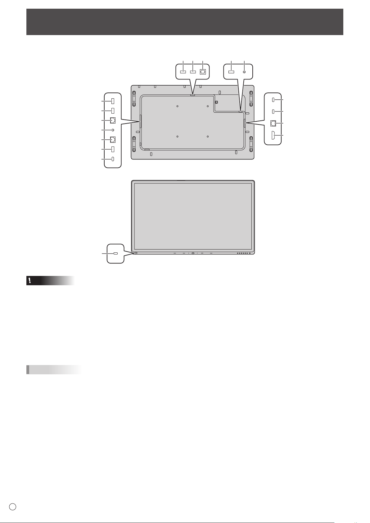
7. Line out Audio output terminal
n
Rear view
1
2
4
3
5
6
9
7
8
10
11
1714 1213 16
n
Front view
15

13
E
Connecting Peripheral Equipment
8. LAN 2 terminal
• YoucanconnecttotheInternetbyconnectinga
commercially available LAN cable between this terminal
and a network.
9. LAN 1 terminal
• Byconnectingthisterminaltoanetwork,youcanconnect
an external device connected via USB to the network.
10. USB port for storage expansion (USB 3.0 compliant)
• Youcanexpandthestorageusedbythemainsystemon
this terminal by inserting a commercially available USB
storage drive.
11. USB Type C output terminal
• ThisTypeCterminalallowstooutputthevideosource
from this terminal to another USB Type C input terminal
supported display, via a commercially available Type C
cable that support DisplayPort.
12. Optical audio input terminal (S/PDIF)
• Thisterminalisreservedforthehardwareecho
cancellation feature supported by the camera (supplied).
• Connecttheopticalaudiooutputfromthecameraandthis
optical audio input terminal via an S/PDIF cable (supplied).
13. USB port for camera 1
• ConnectthecameratothisterminalwiththeUSBAtoB
cable (supplied).
14. USB port for external source (USB 3.0 compliant)
• ConnectaUSBdevicetothisterminal.
• ThisUSBinputterminalservesanextensionofthe
external source devices.
15. USB port for external source (USB 3.0 compliant)
• ConnectaUSBdevicetothisterminal.
16. 3.5 mm jack for service
• Onlyforservicetechnicians.
17. USB port for camera 2
• Connectthecameratothisterminalwiththe3.5mmmini
jack to USB A cable (supplied).
14
E
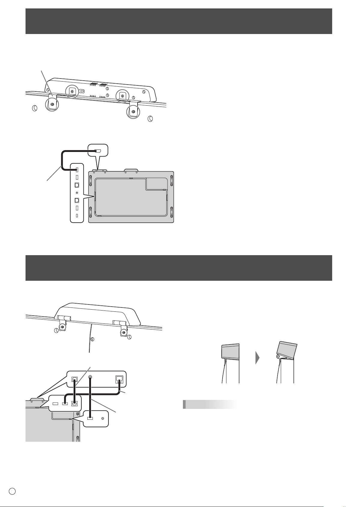
Mounting an IoT sensor hub
It is possible to mount an IoT sensor hub in the following position.
IoT sensor hub
mounting bracket
1
*
2
Micro USB cable
1. Attach the supplied IoT sensor hub mounting brackets
(L/R) to the IoT sensor hub with the supplied IoT
sensor hub screws (M3) (x2).
2. Fix the IoT sensor hub mounting brackets (L/R) to this
monitor with supplied knurled screws (M3) (x2).
* The IoT sensor hub mounting brackets fit into the recess
of this monitor.
Mounting a camera
It is possible to mount a camera in the following position.
3.5 mm mini jack to
USB A cable (supplied)
USB A to B cable
(supplied)
S/PDIF cable (supplied)
1. Attach the supplied camera with the supplied knurled
screws (M3) (x2).
The camera can be tilted downward.
TIPS
• Thecableclamp(supplied)canbeusedtoclampthe3.5
mm mini jack to USB A cable (supplied).
• Attachthesuppliedcableclamptoaflatsurface.Donot
attach over a vent.
• Removeanydustordirtbeforeattaching.
15
E
Caution
• Useonlythepowercordsuppliedwiththemonitor.
1. Turn off the main power switch.
2. Plug the power cord (supplied) into the AC input
terminal.
3. Plug the power cord (supplied) into the power outlet.
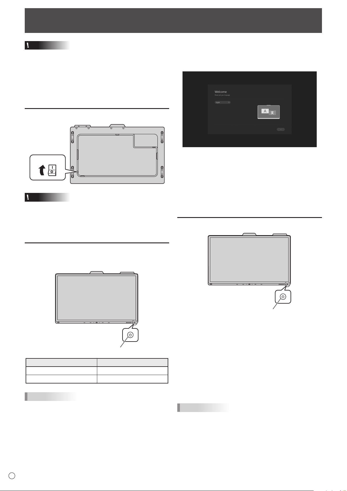
Preparing the Remote Control Unit
Remote control operation range
The operation range of the remote control unit (PN-ZR02,
optional) is approx. 16.4 feet (5 m) at an angle of approx.
10° from the center to the top/bottom/right/left of the remote
control sensor.
10
°1
0°
10°
10°
Remote control sensor
16.4
feet
(5 m)
TIPS
• Donotexposetheremotecontrolunittoshockbydropping
or stepping on it. This could lead to a malfunction.
• Donotexposetheremotecontrolunittoliquids,anddonot
place it in an area with high humidity.
• Theremotecontrolunitmaynotworkproperlyiftheremote
control sensor is under direct sunlight or strong lighting.
• Objectsbetweentheremotecontrolunitandtheremote
control sensor may prevent proper operation.
• Replacethebatterieswhentheyrunlowasthismay
shorten the remote control’s operation range.
• Ifafluorescentlightisilluminatedneartheremotecontrol
unit, it may interfere with proper operation.
• Donotuseitwiththeremotecontrolofotherequipment
such as air conditioner, stereo components, etc.
Installing the batteries
1. Placeyourfingeronthepartmarkedwiththe▲,and
then pull the cover off.
2. See the instructions in the compartment and put in the
batteries (supplied with the PN-ZR02 (optional)) with
their plus (+) and minus (-) sides oriented correctly.
3. Close the cover.
TIPS
• Whenthebatteriesbecomeexhausted,replacethemwith
new (commercially available) batteries.
• Usemanganese(R03(“AAA”size))oralkaline(LR03
(“AAA” size)) batteries only.
• Thesuppliedbatteriesmaybecomeexhaustedquickly
depending on how they are stored.
• Ifyouwillnotbeusingtheremotecontrolforalongtime,
remove the batteries.
Connecting the Power Cord
Main power switch
1
AC input terminal
2
Power cord
(Supplied)
For power outlet
3
1
16
E
Caution
• Turnonthemonitorfirstbeforeturningonthecomputeror
playback device.
• WhenswitchingthemainpowerswitchorthePOWER
button off and back on, always wait for at least 5 seconds.
A short interval may result in a malfunction.
• Tokeeptheperformance,putthemonitorinthePoweroff
state once a day.
Turning on the main power
Main power switch
Caution
• Themainpowermustbeturnedon/offwiththemainpower
switch. Do not connect/disconnect the power cord or turn
the breaker on/off while the main power switch is on.
• Foracompleteelectricaldisconnection,pulloutthemain
plug.
Turning power on
Press the POWER button on this monitor to turn the power
ON.
Power LED / POWER button
Status Status of the monitor
White lit Power on
Amber lit Power off
TIPS
• Youcanturnonthepowerautomaticallyinresponsetothe
people motions.
(When “In-Device Motion Sensor” is set to “On”.)
The operating range is approx. 32.8 feet (10 m).
Turning Power On/Off
n
Operations after first power-on
When the monitor is turned on for the first time after being
shipped from the factory, the setting screen will be displayed.
Configure the settings according to the screen.
About Operation Mode
Mode1:
• Thismonitorgoesintostandbymodewhenthereisno
signal for 5 minutes.
Mode2:
• Thismonitordoesnotgointostandbymodeevenifno
signal continues.
Turning power off
Power LED / POWER button
When “Operation Mode” is set to “Mode1”
Press the POWER button to turn the power OFF (standby
mode).
When “Operation Mode” is set to “Mode2”
When you press the POWER button, the backlight will be
turned off.
To turn the power OFF (standby mode):
1. Long press the POWER button.
The recognition screen appears.
2. Touch [STANDBY].
The power is turned off (standby mode).
TIPS
• Whenthemainpowerswitchisoff,themonitorcannotbe
turned on.
17
E
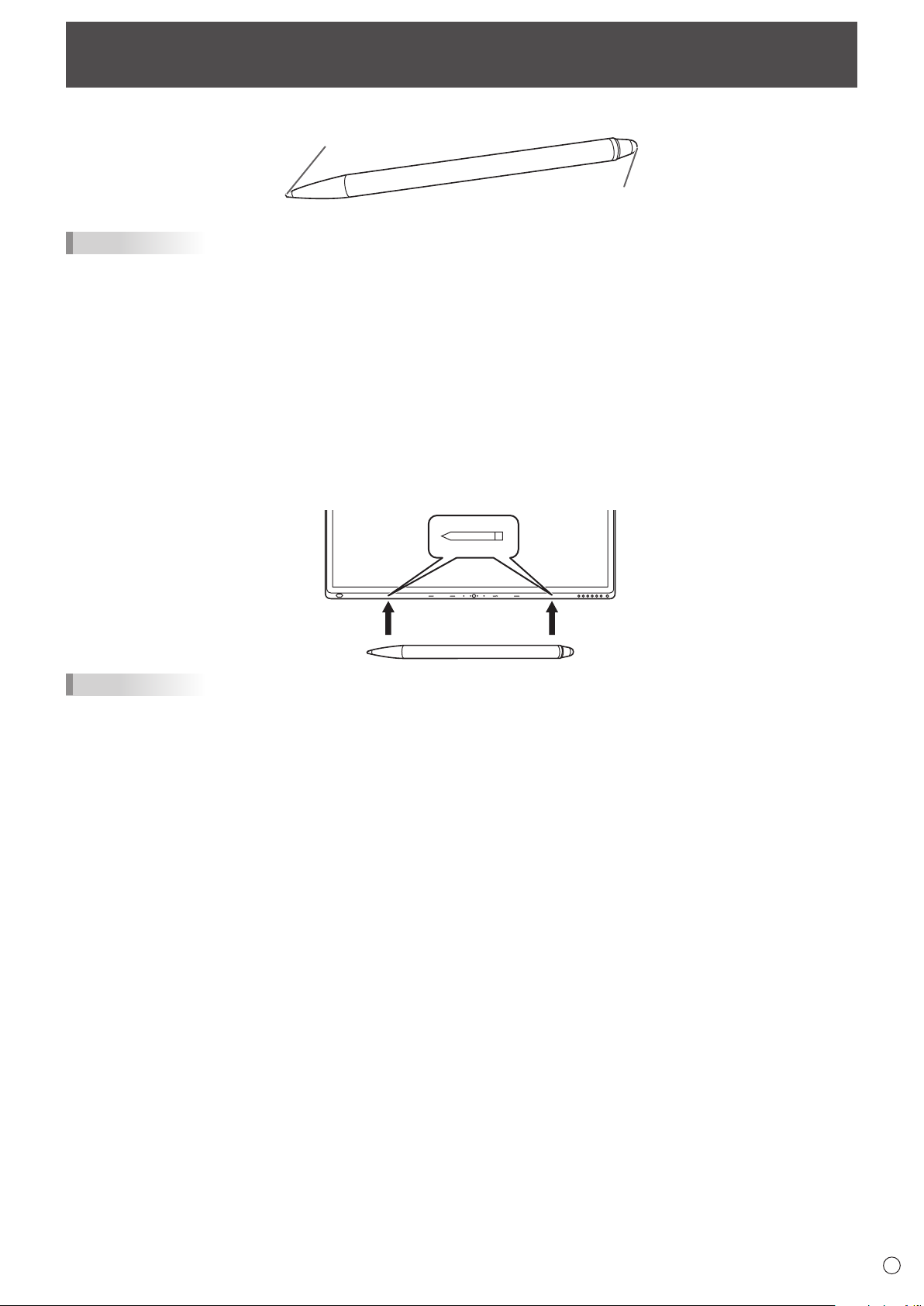
Touch Pen
Pen
Eraser
TIPS
• Incorrectoperationmayresultifyourfingeristooclosetothetipofthepen.
• Holdthetouchpenwithyourbarehand.
The screen will not respond if you wear a glove.
• Whenmultipletouchpensareused,touchpositionsandtouchpeninformation(color,thickness,etc.)maybecome
interchanged, and lines may break.
- When touched simultaneously.
- When touch pens are moved near each other.
• Donotpressthepentiponotherthanthescreen.Thismaycausemalfunctioning.
• Ifthepentipbecomeswornordamaged,replacethetouchpen.Topurchaseanewtouchpen,consultyourdealer.
• SupportWindowsInk.
• Supportpen,eraser,fingermode.
The supplied touch pen is attached to this monitor.
TIPS
• Donotattachanythingotherthanthesuppliedtouchpen.
• Magnetisusedtoattachthesuppliedtouchpen.Donotmoveclosewatchormagneticcardtoit.
18
E
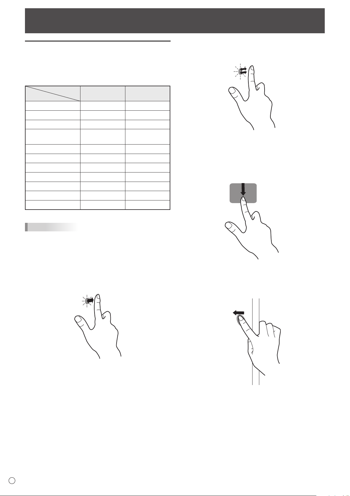
Touch action
Touch action
Touch actions that can be used with this monitor differ
according to operating system and application. The functions
of touch actions are also different. For details, check operating
system Help and the application’s support documentation.
Operating system
Touch action
Windows 8.1 / 10 Chrome OS
Single-tap Yes Yes
Double-tap Yes Yes
Swipe Yes Yes
Swipe from edge of
screen
Yes Yes
Drag-and-drop Yes Yes
Flicks Yes Yes
Press-and-hold Yes Yes
Slide to pan Yes Yes
Zoom Yes Yes
Press-and-tap No Yes
Rotate Yes Yes
TIPS
• OntheMac,theactionsaretheequivalentmouseactions.
(Single touch only.)
n
Common finger and touch pen actions
Single-tap
Same action as left-clicking a mouse.
Touch with your finger/touch pen.
Double-tap
Same action as double-clicking a mouse.
Quickly touch twice with your finger/touch pen.
When double-tapping with your finger, be sure to lift your
finger sufficiently off the screen after the first tap. If there
is insufficient distance between the screen and your finger,
double-tap will not take place.
Swipe
Touch the screen with your finger/touch pen, move without
lifting, and then stop.
Swipe from edge of screen
After touching the edge of the monitor with your finger/touch
pen, move horizontally without releasing your finger/touch pen
and then stop.
19
E
Touch action
Drag-and-drop
Same action as drag-and-drop with a mouse.
Touch the screen with your finger/touch pen and move without
lifting. When you have finished the movement, lift your finger/
touch pen.
Flicks
Flick your finger/touch pen in the direction of the function you
want to use.
Flick your finger
Press-and-hold
Same action as right-clicking a mouse.
Press briefly with your finger/touch pen, and then lift your
finger/touch pen from the screen.
Slide to pan
With your finger/touch pen touching the screen, move it up
and down to scroll the screen.
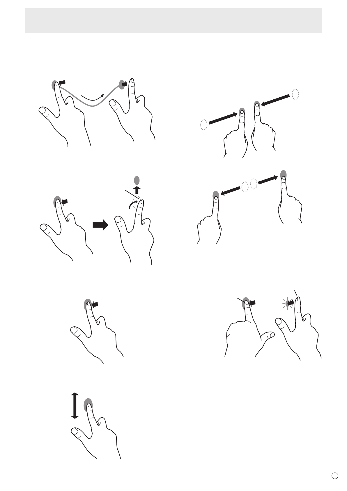
n
Finger actions
Zoom
Use in a screen that is capable of enlargement/reduction.
Touch the screen with two fingers and move your fingers
closer together to reduce the view, or apart to enlarge the
view.
Reduction
Enlargement
Press-and-tap
Same action as right-clicking a mouse.
With one finger touching the screen, tap once (single tap) with
another finger.
With one finger touching
Tap once (single tap) with another finger
20
E
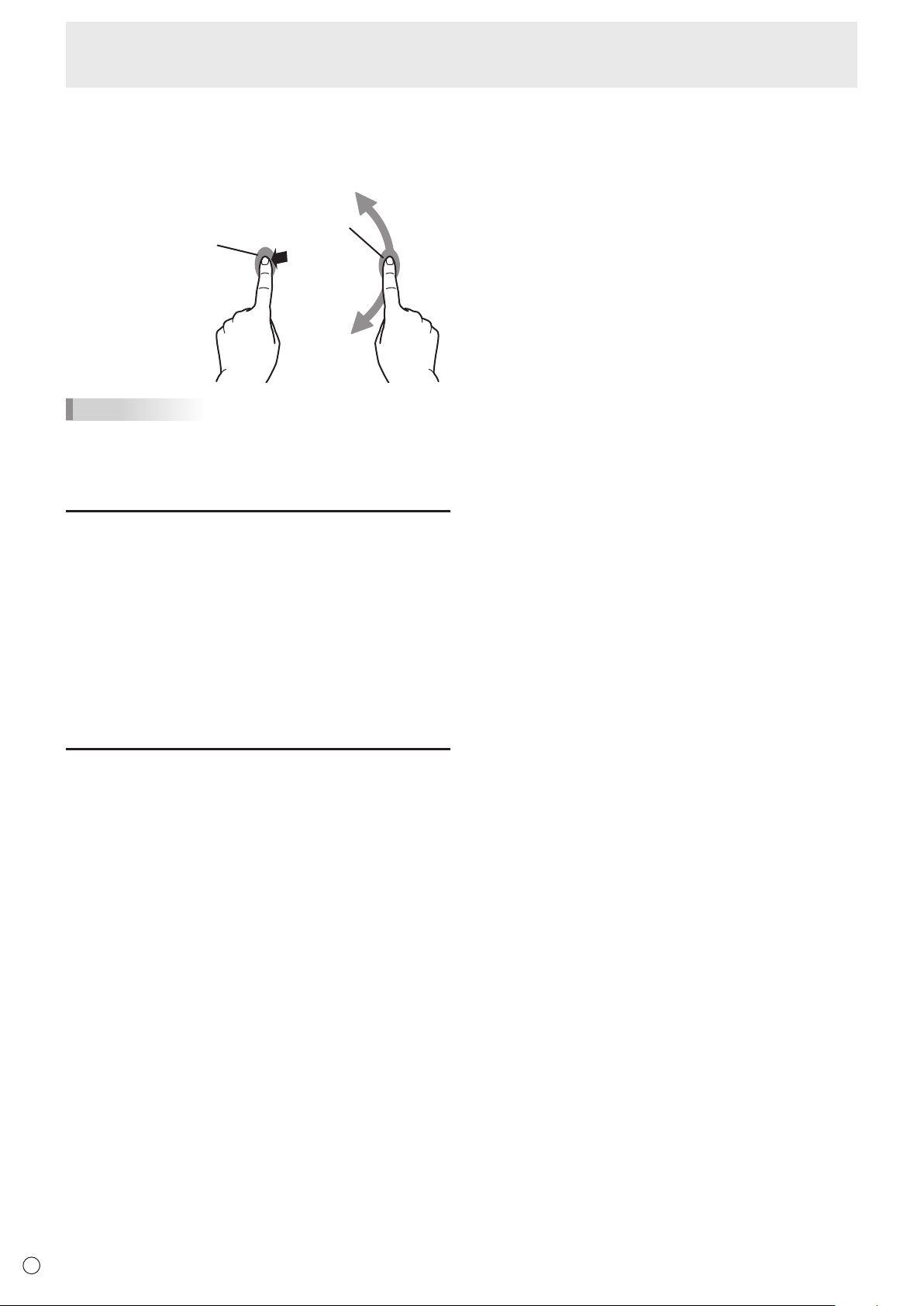
Touch action
Rotate
Use this action in a screen that is capable of image rotation.
Touch the center point of the rotation with one finger. While
holding that finger still, move another finger in the desired
direction of rotation.
With one finger touching
Move another finger in the
desired direction of rotation
TIPS
•
The screen may not respond correctly in the following cases:
- Touch gesture is too quick.
- The distance between the two points is too short.
- The two points intersect.
Other functions
In Windows 8.1/10, input panel functions can be used.
For information on these functions, see Windows Help.
Input panel :
A software keyboard and an input panel with handwriting
recognition appear on the screen.
In Windows 8.1/10, the ink function of Microsoft Office can be
used.
Handwritten comments can be written, and handwriting can
be recognized.
For details, see Microsoft Office Help.
Cautionary points
• Notethefollowingwhentouchingbyfinger:
- Do not touch with a wet finger.
- Touch with the ball of your finger.
- Touch with your bare finger.
The screen will not respond if you are wearing a glove.
• Donotusethetouchpenforanypurposeotherthantouch
panel operation.
• Donotpresshardonthepentip.
• Thismaynotoperatecorrectlyifthereisaninverter
fluorescent light nearby.
• Ifthereisdirtorforeignmatteronthetipofthetouchpen,
remove it. Foreign matter may damage the screen.
• Thetouchpenpositionmayoccasionallydeviateinthe
login screen of the connected computer. In this case, use
the keyboard or mouse.
• IftheUSBcablebecomesdisconnected,thetouch
panel may not operate correctly after the USB cable is
reconnected. In this case, restart the computer.
21
E
Basic Operation
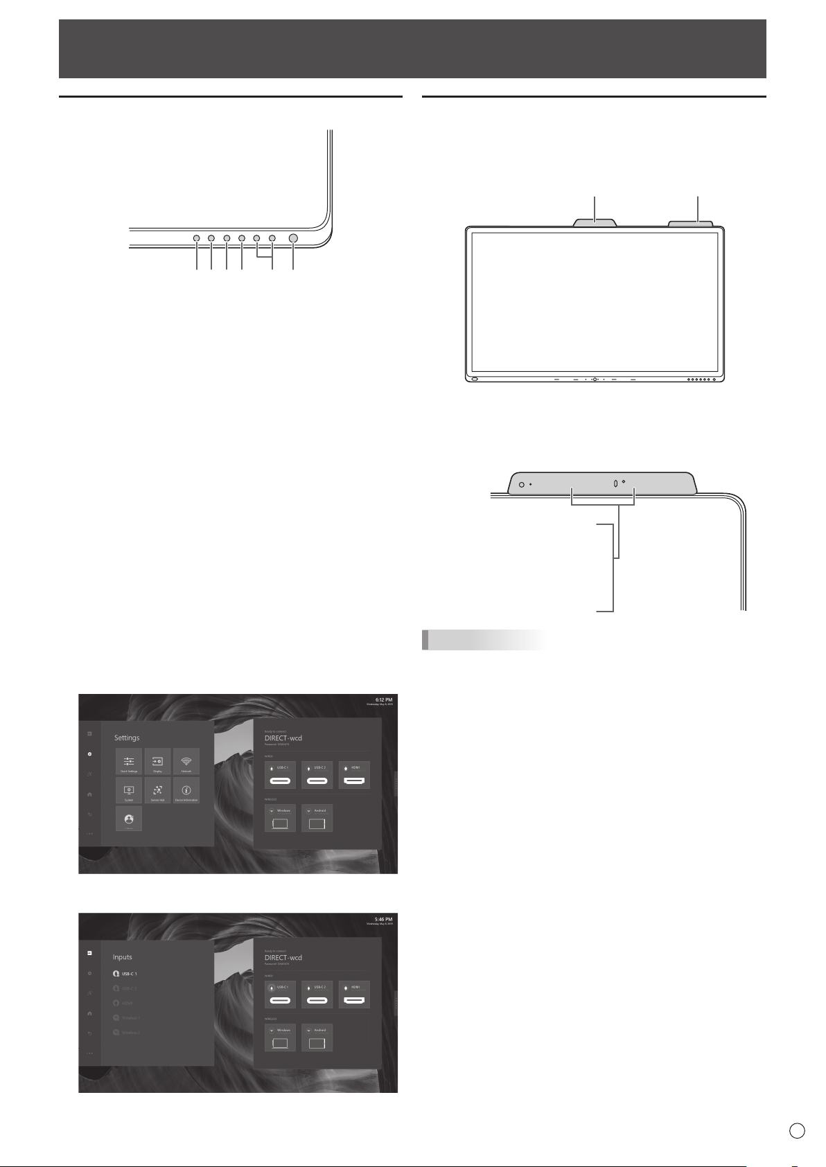
Button Operation
5 4 3 2
6 1
1. POWER button
See page 16.
2. VOLUME DOWN / UP buttons
2.1 No device connection
Controlling this monitor volume up/down.
2.2 Device connection
Controlling input device volume up/down.
(Windows only. Must be connected with a USB cable.)
3. MUTE button
3.1 No device connection
Controlling this monitor volume mute, button LED
lights red.
3.2 Device connection
Controlling input device volume mute, button LED
lights red.
(Windows only. Must be connected with a USB cable.)
4. MIC MUTE button
Controlling input device mic volume mute, button LED
lights red.
(Windows only. Must be connected with a USB cable.)
5. MENU button
Pressing the MENU button to quick launch the menu.
6. INPUT button
Pressing the INPUT button to quick open the Inputs menu.
IoT accessories Operation
1. Camera module
Camera module build with camera and Mic array. Which
provide conference video function.
Camera IoT sensor Hub
2. IoT Sensor Hub
IoT Sensor Hub is an independent accessory which
included 5 features (Temperature / Humidity / CO2 / TVOC
/ Motion).
Motion Sensor
IR Sensor
CO2/TVOC Sensor
Light Sensor
Air Quality/Temperature Sensor
TIPS
• UsercanseetheSensordatabyopenIoTsensor
Dashboard or check data in Action panel – Settings –
Sensor Hub.
22
E
Basic Operation
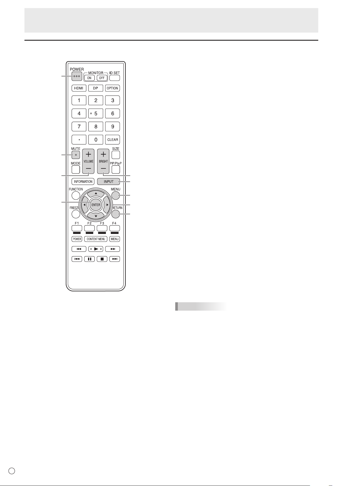
4
5
8
6
1
2
7
39
1. POWER
When “Operation Mode” is set to “Mode1”
Press the POWER button to turn the power OFF (standby
mode).
When “Operation Mode” is set to “Mode2”
When you press the POWER button, the backlight will be
turned off.
2. MUTE
Turns off the volume temporarily.
Press the MUTE button again to turn the sound back to
the previous level.
3. VOLUME +/- (Volume adjustment)
Pressing+or-displaystheVOLUMEmenu.
Press+or-toadjustthevolume.
4. INPUT (Input mode selection)
Each time you press this button, the input mode changes.
5. MENU
Displays and turns off the menu screen.
6. Cursor
These buttons are used to perform operations such as
selecting items, changing adjustment values, and moving
the cursor.
7. ENTER
Confirms the setting.
8. RETURN
Returns to the previous screen.
9. BRIGHT +/- (Brightness adjustment)
Press+or-toadjustthebrightness.
TIPS
• Otherbuttonsarenotusedonthismonitor.
Using the remote control unit (option)
23
E
Menu Items
Displaying the menu
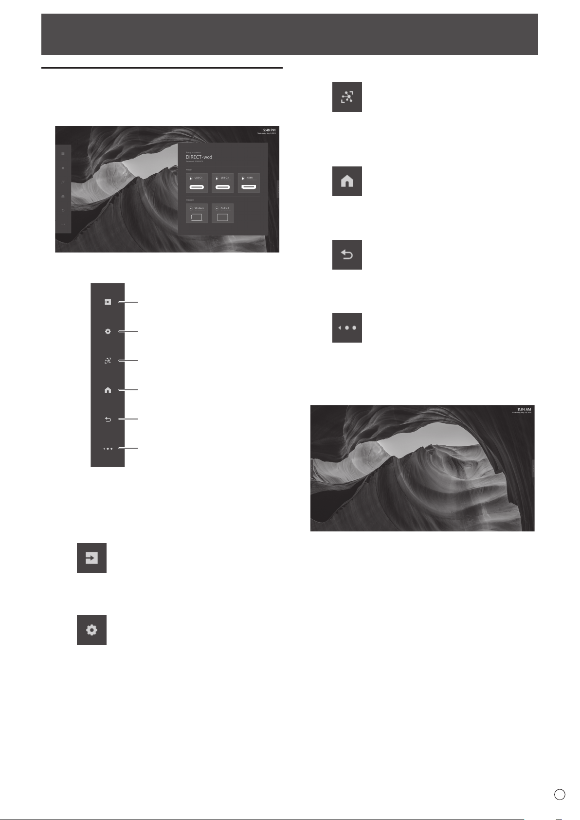
1. Home screen
The Home Screen is the default screen that users will see
when they launch this monitor.
2. Action panel
Input Button
Settings Button
Dashboard Button
Home Button
Back Button
Hide Button
2.1 Action Panel Buttons
The Action Panel buttons can be tapped anytime
as long as the Action Panel is showing. The below
documentation links provide deeper dive into each
button’s expanded content.
Input Button
The Input Button opens up the Inputs Panel and allow
the user to switch sources and get source information.
Settings Button
The Settings button will open up the Settings panel
and allow the user to change device settings.
Dashboard Button
Displays the measurement results of the IoT sensor.
(Temperature, Humidity, CO2 Levels, TVOC Levels,
Motion)
Home Button
The Home button can be tapped at any time to get the
user back to the home screen.
Back Button
It will allow users to go back inside apps and also
within the menu.
Hide Button
The Hide button will turn the Action Panel into the
Action Thumb. On external source screen it will hide
the Action Panel and menu completely.
3. Action Thumb
The Action Thumb is meant to be a smaller version of the
Action Panel so that it can be present on the screen and
not block the content as much as possible.
24
E
Menu Items
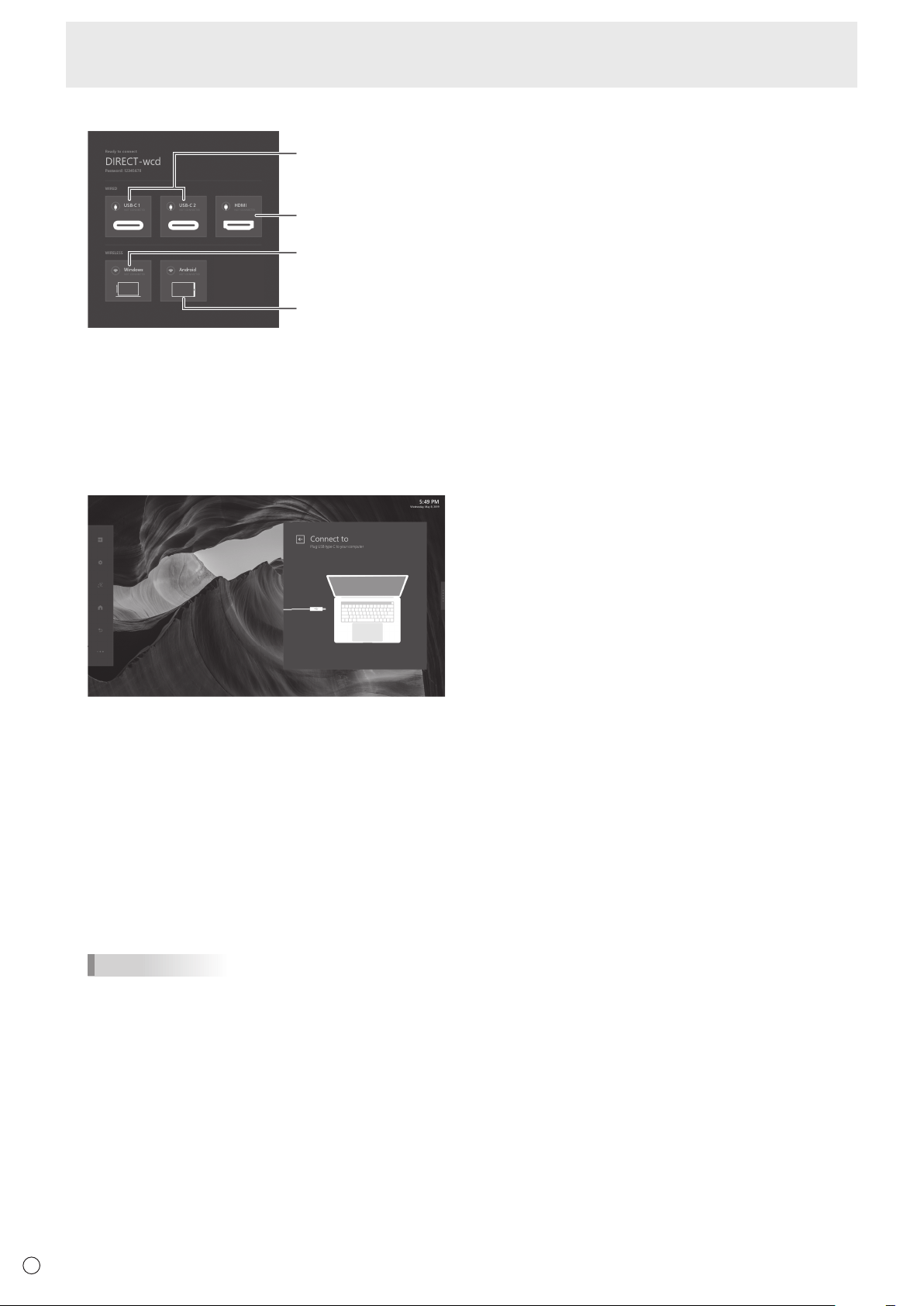
4. Instruction panel
USB Type C
instructions
HDMI instructions
Windows instructions
Android instructions
The instruction panel is broken down to different sections
each with a different purpose.
Wired Instructions
The wired section will show you the status of the wired
connections within each of the boxes. If the USB icon
has a green status then that means that the connection is
active. If you want further instructions on how to plug into
each of the wire types, you can simply click into the box.
WirelessInstructions(Windows10,Android)
The wireless section will show you the status of each
wireless connections within each of the boxes. If the
Wireless LAN icon has a green status then that means that
the connection is active. If you want further instructions
on how to connect to each of the wireless types, you can
simply click into the box.
Depending on the operating system used, the procedure
may differ slightly from the instructions described here.
Older or upcoming new operating systems may require
additional steps to connect to the monitor.
TIPS
• Whenthewirelessconnectionislostduetoexternal
influences, low bandwidth or other causes, you need to
reconnect the device.
• Connectionstoalldevicesisnotguaranteed.
25
E
Menu Items
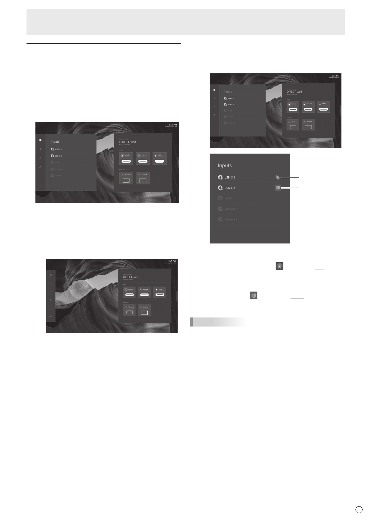
Multi-input source
This monitor can detect up to two external sources
input. For Multi-input source, this monitor can also
support PbyP display.
Main Source
Sub Source /
PbyP function
Main Source
Main source default with the first input source which
go with Main Source icon (
) and be the Left place in
PbyP mode.
Sub Source
The second input source be the sub-source which go
with PbyP icon (
), and be the Right place in PbyP
mode.
TIPS
• TouchfunctiondefaultsupportintheleftplaceinPbyP
mode.
1.2 Wireless input source
This monitor support Windows 10 / Android system
device with Single source or Muti-sources wireless
casting and PbyP display.
Main function in Action Panel
The Action Panel can be controlled all panel setting which
including OSD functions and input source switching. The
below documentation links provide deeper dive into each
button’s expanded content.
1. Inputs
The Input Button opens up the Inputs Panel and allow the
user to switch wire or wireless sources and get source
information.
1.1 Wire input source
Single-input source
Single input source, this monitor will auto detect
and switch to input device. Supporting Touch Back
function, user can operate this monitor to control the
other.
Auto detect input source in dashboard and switch to
device directly.
Both Audio and Video can be switched.
26
E
Menu Items
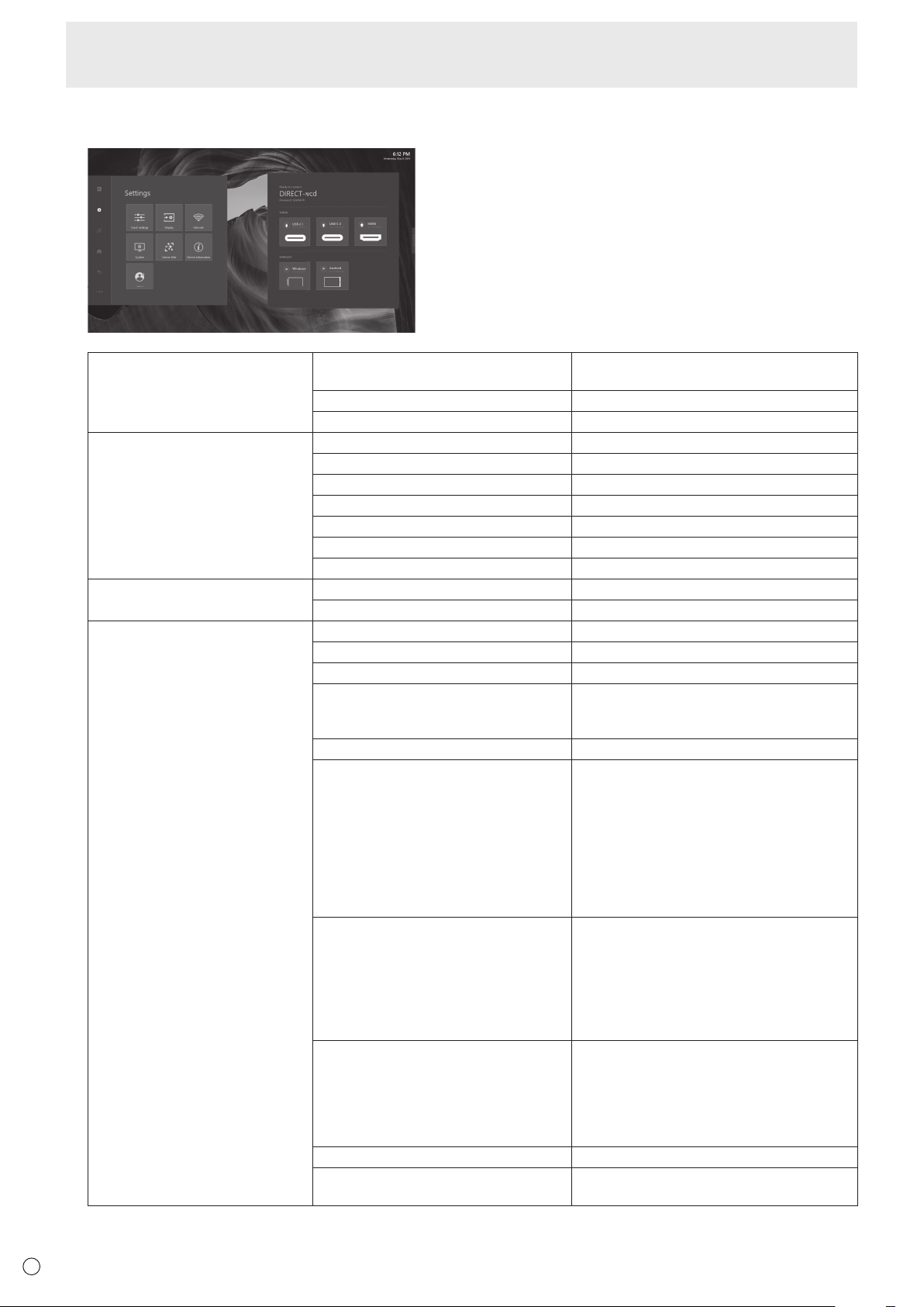
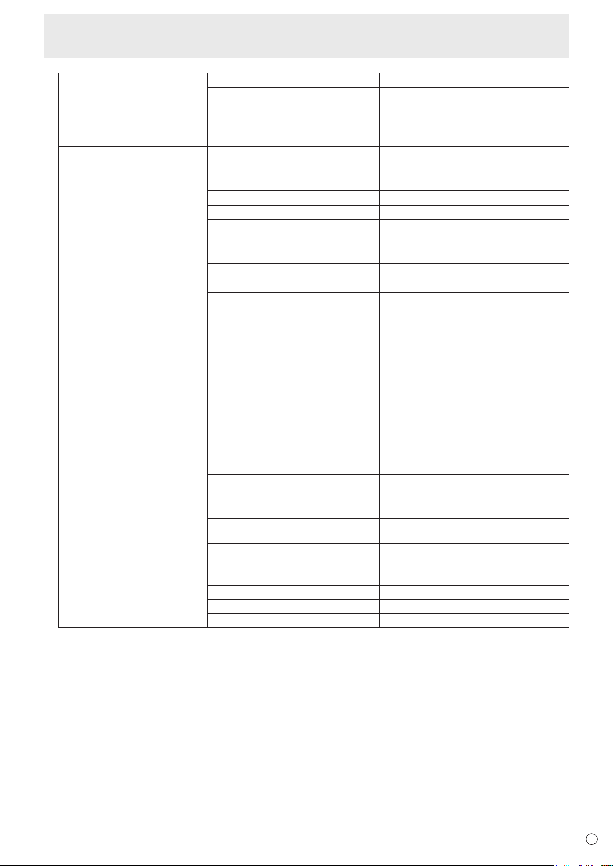
2. Settings
The Settings button will open up the Settings panel and allow the user to change device settings.
Quick Settings Volume 0-100%
Mute
Mic toggle On/Off
Brightness 0-100
Display Contrast 0-100%
Sharpness 0-100%
Color 0-100%
Tint 0-100%
SOURCES ALIAS (Default: USB-C 1) Edit
SOURCES ALIAS (Default: USB-C 2) Edit
SOURCES ALIAS (Default: HDMI) Edit
Network TCP/IP DHCP/Manual
Proxy None/Manual
System High Contrast On/Off
Font Size 4 steps
24-Hour Time On/Off
Set Automatically On/Off
Date, Time (When “Set Automatically” is set
to “Off”.)
Time Zone Select
Idle Screen Time 1 minute
5 minutes
10 minutes
15 minutes
30 minutes
1 hour
Never
Can not be set longer than “Power Saving
Timeout”.
Power Saving Timeout
*
5 minutes
30 minutes
1 hour
3 hours
6 hours
12 hours
Never
Language English
Español
Français
Deutsch
Italiano
Русский
Bluetooth On/Off
Temperature Celsius
Fahrenheit
27
E
Menu Items
System LAN1 Network On/Off
USB-C Video Stream SST (Single Stream Transport) / MST (Multi
Stream Transport)
Images may not be displayed properly
depending on the computer (video card) to
be connected.
Sensor Hub Enable Sensors On/Off
Device Information OS/OS version
Model
Hardware ID/Serial number
Software License
Open Source Library
Admin Device Wireless LAN Name
Choose A New Wallpaper Choose
Install New Apps Choose
Country Select
Province / Region / State Select
City Select
Operation Mode Mode1
Power Saving Timeout: 5 mins (Standby
mode)
In-Device Motion Sensor: On
Wake On LAN: On
IoT Sensor Hub Always On: Off
Mode2
Power Saving Timeout: 5 mins (Backlight
off)
In-Device Motion Sensor: On
Wake On LAN: On
IoT Sensor Hub Always On: On
Change User Passcode Change
Change Admin Passcode Change
OTA Firmware Updates Update
USB Firmware Updates Update
Firmware Update Window Start Time
End Time
All Reset Reset
In-Device Motion Sensor
*
On/Off
Smart Switcher On/Off
Wake On LAN
*
On/Off
IoT Sensor Hub Always On
*
On/Off
LAN1 Always-on Connection On/Off
*: When “Operation Mode” is set to “Mode1”, these settings can not be changed.
About “LAN1 Network” and “LAN1 Always-on Connection”
• “LAN1Network”setto“On”tousetheLAN1terminal.
• DisconnecttheUSBTypeCcableorUSBAtoBcable,“LAN1Network”willbesetto“Off”automatically.
If “LAN1 Always-on Connection” is set to “On”, “LAN1 Network” will not be set to “Off” even if the cable is disconnected.
28
E
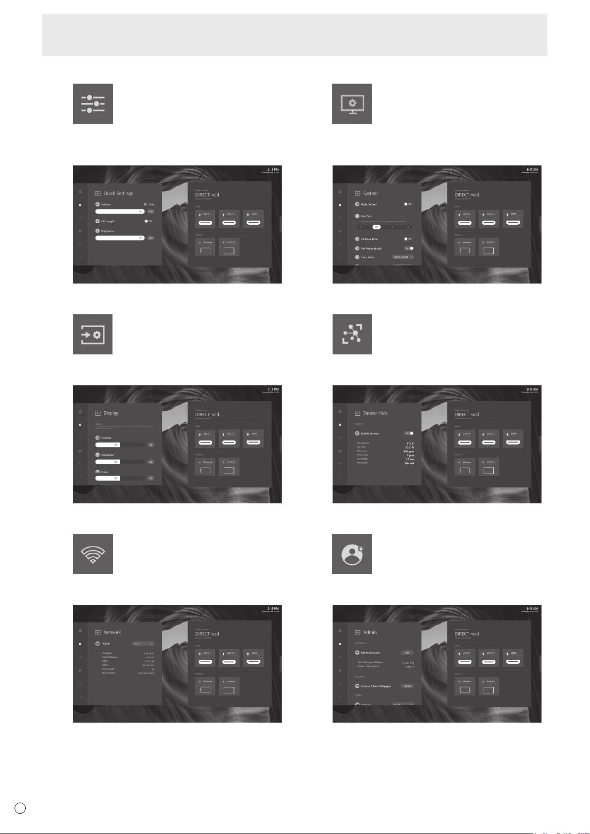
2.1 Quick Settings
In Quick Settings menu, it can be controlled Volume /
Mic toggle / Brightness in both this monitor and external
devices.
2.2 Display
The Display settings will only affect external sources.
The Display settings will not be applied to this monitor.
2.3 Network
Network menu is setting the LAN connection between
this monitor and external devices.
2.4 System
System menu is focus on this monitor adjustment
which including High Contrast / Font Size / Time
setting and language.
2.5 Sensor Hub
Enable sensor data, user can see the sensor value
below.
2.6 Administration (Admin)
For others setting, admin collects other setting items.
User can also update new firmware in Admin menu.
Menu Items
29
E
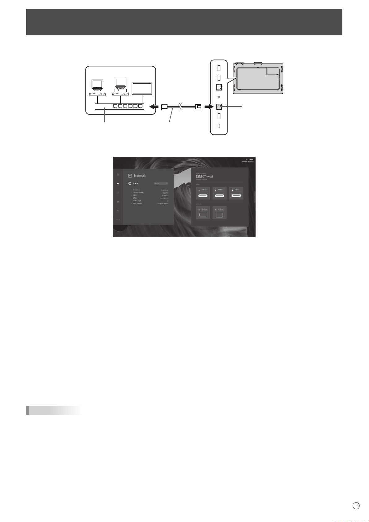
Network
This monitor can be connected to a LAN.
The connection requires a commercially available LAN cable (UTP cable, Category 5, straight through).
LAN 2 terminal
LAN cable (commercially
available, straight)
Hub
Network (LAN)
n
Settings to connect to a LAN (LAN 2)
1. TCP/IP
If your LAN has a DHCP server and you wish to obtain an address automatically, change this setting to DHCP.
To set the address manually, set this to Manual.
1.1 IP Address
If the TCP/IP is set to Manual, specify an IP address.
1.2 Default Gateway
If the TCP/IP is set to Manual, specify a default gateway.
1.3 DNS 1
If the TCP/IP is set to Manual, specify a DNS.
1.4 DNS 2
If the TCP/IP is set to Manual, specify a DNS.
1.5 Subnet Mask
If the TCP/IP is set to Manual, specify a subnet mask.
1.6 MAC Address
Show the MAC Address.
2. Proxy
If your LAN has a proxy server and you wish to use it, change this setting to Manual, otherwise set to None.
2.1 Proxy Hostname
If the Proxy is set to Manual, specify a proxy hostname.
2.2 Proxy Port
If the Proxy is set to Manual, specify a proxy port.
TIPS
• ThismonitorsupportsapplicationsoftwareRoomViewfromCrestronElectronics,Inc.
This is a function to connect a system developed by Crestron Electronics, Inc. which manages and controls multiple system
devices connected to the network.
For details of Crestron Connected, refer to the Crestron Electronics, Inc. website. (Provided only In English.)
http://www.crestron.com/
For the download of RoomView Express, refer to the Crestron Electronics, Inc. website. (Provided only In English.)
http://www.crestron.com/getroomview

30
E
Troubleshooting
If you are experiencing any problem with your display, before
calling for service, please review the following troubleshooting
tips.
There is no picture or sound.
• The power LED is off.
- Is power supplied to this monitor?
- Is the power cord disconnected? (See page 15.)
- Is the main power switch off? (See page 16.)
• The power LED lights amber.
- This monitor is in standby mode. Turn on the power. (See
page 16.)
Remote control does not work.
• Arethebatteriesinsertedwithpolarity(+,-)aligned?(See
page 15.)
• Arethebatteriesexhausted?
• Pointtheremotecontrolunittowardthemonitor’sremote
control sensor. (See page 15.)
There is a picture but no sound.
• Is the sound muted?
• Makesurethevolumeisnotsettominimum.
• Areaudiocablesconnectedproperly?
Unstable video.
• Thesignal may be incompatible.
The video from the HDMI input terminal does not appear
properly.
• UsethesuppliedHDMIcable.
• Ifusingacommerciallyavailablecable,does the HDMI
cable support 4K, and is it HDMI standard compliant? The
monitor will not work with cables that are not standard
compliant.
• Istheinputsignal compatible with this monitor? (See page
33.)
Control buttons do not work.
There is no picture.
• Load noises from outside may be interfering with normal
operation. Turn off the main power and turn it on after
waiting at least 5 seconds, and then check the operation.
The touch panel does not respond.
• Isthe USB cable connected properly?
The monitor makes a cracking sound.
• Yo u may occasionally hear a cracking sound from the
monitor. This happens when the cabinet slightly expands
and contracts according to change in temperature. This
does not affect the monitor’s performance.
31
E
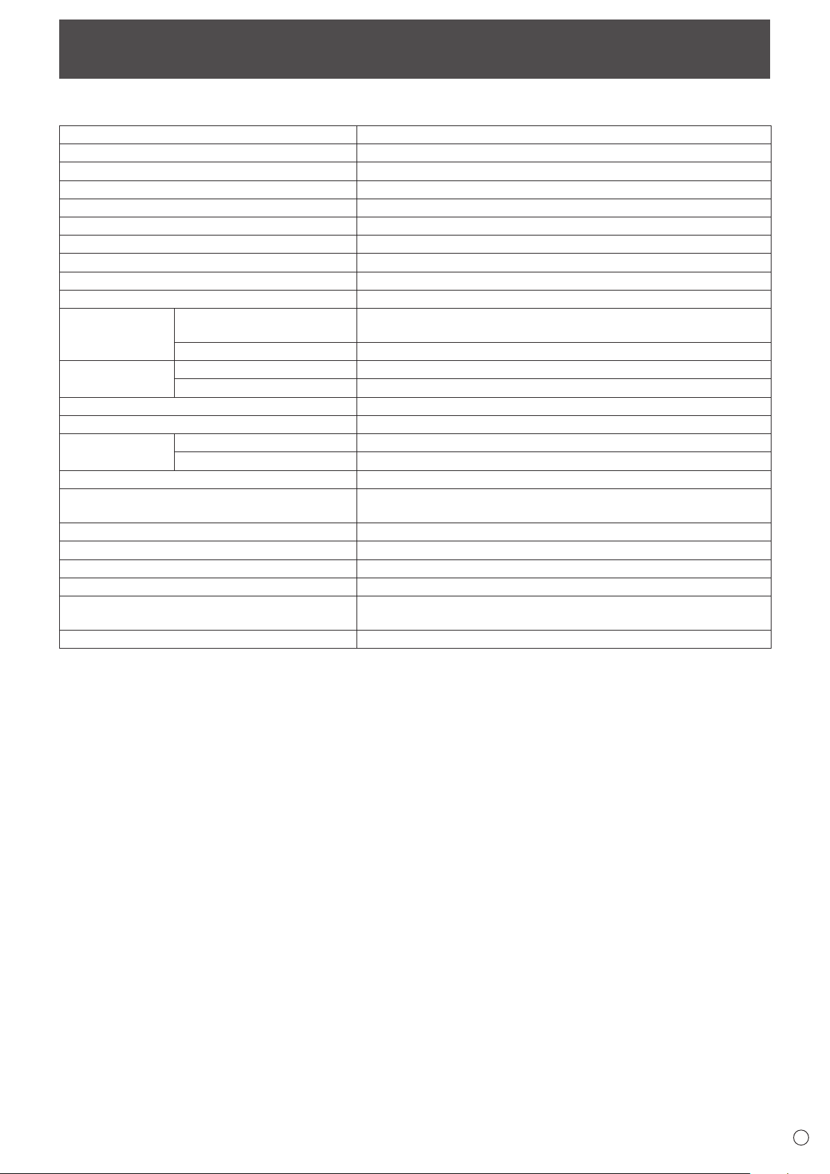
Specifications
n
Product Specifications
Model PN-CD701
LCD component
70" Class [69-1/2 inch (176.6 cm) diagonal] TFT LCD
Max. resolution (pixels)
3840 x 2160
Max. colors
Approx. 1.06 billion colors
Pixel pitch
0.401
mm
(H) × 0.401
mm
(V)
Brightness (typical) 350 cd/m
2
*
1
Contrast ratio (typical) 4000: 1
Viewing angle
176°right/left/up/down(contrastratio≥10)
Screen active area inch (mm)
60-9/16 (W) x 34-1/16 (H) (1538.9 x 865.6)
Computer input signal
USB type C (alternate mode)
Input terminals
Video HDMI x 1
USB Type C x 2
Audio
3.5 mm mini stereo jack x 1
Output terminals
Video
USB Type C x 1
Audio
3.5 mm mini stereo jack x 1
LAN terminal 10 / 100 / 1000 Mbps x 2
Speaker output 12W+12W
Touch Panel
Detection method Capacitive type
Computer connector USB (2.0 compliant) (Type B) x 1, USB Type C x 2
Wireless LAN IEEE802.11ac/n/a/g/b compliant
Bluetooth
4.2 compliant
Supported protocols: A2DP, AVRCP, GATT, GAP, HID
Power requirement AC 100 V - 240 V, 4.2 A, 50/60 Hz
Operating temperature
*
2
*
3
41°F to 95°F (5°C to 35°C)
Operating humidity
*
3
20% to 80% (no condensation)
Power consumption (Standby mode) 370 W (2.0 W)
Dimensions (excluding protrusions) inch (mm)
Approx. 63-15/16 (W) x 3-9/16 (D) x 38-7/16 (H)
(1623.5 x 90.0 x 976.5)
Weight lbs. (kg)
Approx. 143.3 (65)
*1 Brightness will depend on input mode and other picture settings. Brightness level will decrease over time. Due to the nature of the
equipment, it is not possible to precisely maintain a constant level of brightness.
*2 Temperature condition may change when using the monitor together with the optional equipments recommended by SHARP.
In such cases, please check the temperature condition specified by the optional equipments.
*3 In addition, check the requirements of the computer and other devices to be connected, and make sure that all requirements are satisfied.
As a part of our policy of continuous improvement, SHARP reserves the right to make design and specification changes for product improvement
without prior notice. The performance specification figures indicated are nominal values of production units. There may be some deviations from
these values in individual units.

32
E
n
Dimensional Drawings
Note that the values shown are approximate values.
3-9/16
[90]
7-7/8
[200]
7-7/8
[200]
7-7/8
[200]
Screw holes for
mounting brackets
Opening width (60-11/16 [1542])
63-15/16 [1623.5]
Opening height
(
34-1/4 [870]
)
38-7/16 [976.5]
1-3/4 [44.5]
1-1/4 [31]
3-11/16
[94]
3-1
1/16
[93]
19-11/16 [500.5]
Unit: inch [mm]
7-7/8
[200]
When mounting the monitor, be sure to use a wall-mount bracket that complies with the VESA-compatible mounting method.
SHARP recommends using M6 screws and tighten the screws.
Note that screw hole depth of the monitor is 3/8 inch (10 mm). Loose mounting may cause the product to fall, resulting in serious
personal injuries as well as damage to the product. The screw and hole should come together with over 5/16 inch (8 mm) length
of thread. Use a bracket which has been approved for UL1678 standard, and which can endure at least 4 times or more the
weight of the monitor.
Specifications
33
E
n
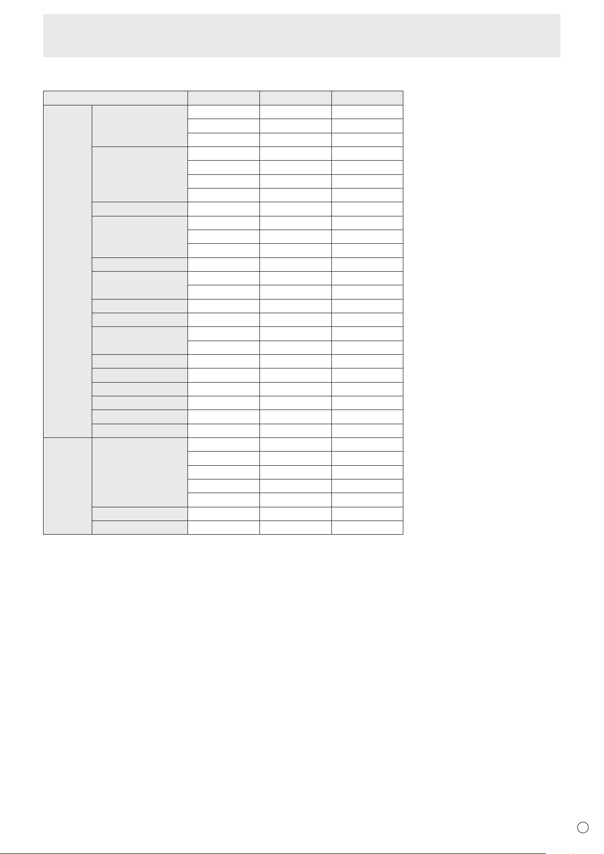
Compatible signal timing
Screen resolution Vsync HDMI USB Type C
VESA 640 × 480 60Hz Yes Yes
72Hz Yes Yes
75Hz Yes Yes
800 × 600 56Hz - -
60Hz Yes Yes
72Hz Yes Yes
75Hz Yes Yes
848 × 480 60Hz - -
1024 × 768 60Hz Yes Yes
70Hz Yes Yes
75Hz Yes Yes
1152 × 864 75Hz Yes Yes
1280 × 768 60Hz - Yes
75Hz - Yes
1280 × 800 60Hz Yes Yes
1280 × 960 60Hz Yes Yes
1280 × 1024 60Hz Yes Yes
75Hz Yes Yes
1360 × 768 60Hz Yes Yes
1400 × 1050 60Hz Yes Yes
1440 × 900 60Hz Yes Yes
1600 × 1200 60Hz Yes Yes
1680 × 1050 60Hz Yes Yes
1920 × 1200 60Hz Yes Yes
Wide 3840 × 2160 24Hz Yes Yes
25Hz Yes Yes
30Hz Yes Yes
50Hz Yes Yes
60Hz Yes Yes
1280 × 720 60Hz Yes Yes
1920 × 1080 60Hz Yes Yes
• Dependingontheconnectedcomputer,imagesmaynotbedisplayedproperlyevenifthecompatiblesignaldescribedaboveisinput.
• TheRGBrangesupportsonlythefullrange.
Specifications
34
E
Specifications
n
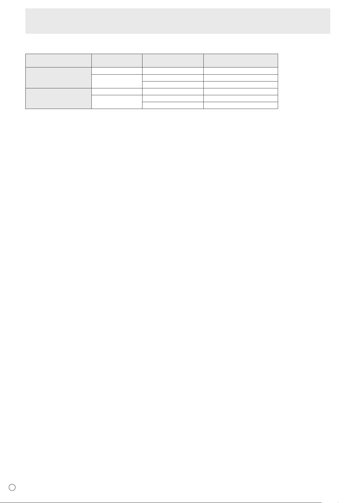
Channels that can be used in wireless LAN
Standard Channel
Frequency band
(center frequency)
USA IEEE802.11b/g/n 1-13ch 2412-2472MHz
IEEE802.11ac/a/n 36/40/44/48ch 5180-5240MHz
149/153/157/161/165ch 5745-5825MHz
CANADA IEEE802.11b/g/n 1-11ch 2412-2462MHz
IEEE802.11ac/a/n 36/40/44/48ch 5180-5240MHz
149/153/157/161/165ch 5745-5825MHz
This device is restricted to indoor use due to its operation in the 5.15 GHz to 5.25 GHz frequency range. FCC requires this
product to be used indoors for frequency range 5.15 GHz to 5.25 GHz to reduce the potential for harmful interference to co-
channel Mobile Satellite systems.
High power radars are allocated as primary users of the 5.25 GHz to 5.35 GHz and 5.65 GHz to 5.85 GHz bands. These radar
stations can cause interference with and/or damage this device.

35
E
Intellectual Property Rights and Other Matters
n
Information on the software license for this product
Software composition
The software included in this product is comprised of various software components whose individual copyrights are held by
SHARP or by third parties.
Software developed by SHARP and open source software
The copyrights for the software components and various relevant documents included with this product that were developed or
written by SHARP are owned by SHARP and are protected by the Copyright Act, international treaties, and other relevant laws.
This product also makes use of freely distributed software and software components whose copyrights are held by third parties.
These include software components covered by a GNU General Public License (hereafter GPL), a GNU Lesser General Public
License (hereafter LGPL) or other license agreement.
Obtaining source code
Some of the open source software licensors require the distributor to provide the source code with the executable software
components. GPL and LGPL include similar requirements. For information on obtaining the source code for the open source
software and for obtaining the GPL, LGPL, and other license agreement information, visit the following website:
https://jp.sharp/business/lcd-display/support/download/source_e.html
We are unable to answer any questions about the source code for the open source software. The source code for the software
components whose copyrights are held by SHARP is not distributed.
36
E
• Wheninstalling,removingormovingthemonitor,ensurethatthisiscarriedoutbyatleast4people.
• Besuretouseawall-mountbracketdesignedordesignatedformountingthemonitor.
• Thismonitorisdesignedtobeinstalledonaconcretewallorpillar.Reinforcedworkmightbenecessaryforsomematerials
such as plaster / thin plastic board / wood before starting installation.
This monitor and bracket must be installed on a wall which can endure at least 4 times or more the weight of the monitor.
Install by the most suitable method for the material and the structure.
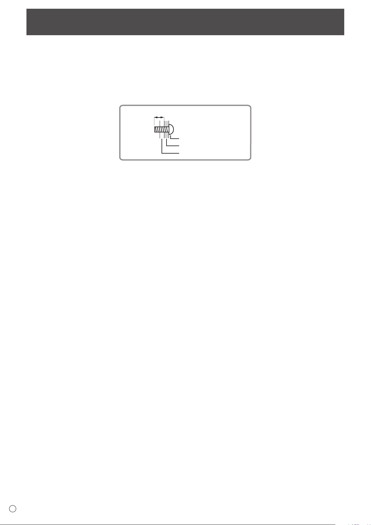
• ToattachaVESA-compliantmountingbracket,useM6screwsthatare5/16inch(8mm)to3/8inch(10mm)longerthanthe
thickness of the mounting bracket.
Screws (M6)
Mounting bracket
Monitor mounting
5/16 - 3/8 inch (8-10 mm)
• Donotuseanimpactdriver.
• Aftermounting,pleasecarefullyensurethemonitorissecure,andnotabletocomeloosefromthewallormount.
• Donotuseanyscrewholesotherthanthoseformountingbrackets,locatedontherearofthemonitor,forinstallation.
• Whenmovingthismonitor,besuretoholditwiththehandles,theunitsidesortheunittop.Donotgraspthescreen,unit
corner or speaker. This may cause product damage, failure, or injury.
• Ifyouneedtotemporarilyplacethemonitoronatableorothersurfaceduringinstallation,spreadathicksoftclothonthe
table to prevent damage to the screen and table.
Mounting Precautions
(For SHARP dealers and service engineers)

PN-CD701 Mu EN19G(1)
