
PN-C861H
PN-C751H
LCD MONITOR
OPERATION MANUAL

IMPORTANT:
To aid reporting in case of loss or theft, please record the
product’s model and serial numbers in the space provided.
The numbers are located in the rear of the product.
Model No.:
Serial No.:
U.S.A. ONLY
3
E
IMPORTANT INFORMATION
WARNING: TO REDUCE THE RISK OF FIRE OR ELECTRIC SHOCK, DO NOT EXPOSE THIS PRODUCT
TO RAIN OR MOISTURE.
CAUTION: TO REDUCE THE RISK OF ELECTRIC
SHOCK, DO NOT REMOVE COVER.
NO USER-SERVICEABLE PARTS
INSIDE.
REFER SERVICING TO QUALIFIED
SERVICE PERSONNEL.
The lightning flash with arrowhead symbol, within
a triangle, is intended to alert the user to the
presence of uninsulated “dangerous voltage”
within the product’s enclosure that may be of
sufficient magnitude to constitute a risk of electric
shock to persons.
The exclamation point within a triangle is
intended to alert the user to the presence of
important operating and maintenance (servicing)
instructions in the literature accompanying the
product.
WARNING:
FCC Regulations state that any unauthorized changes or modifications to this equipment not expressly approved by the
manufacturer could void the user’s authority to operate this equipment.
NOTE:
This equipment has been tested and found to comply with the limits for a Class A digital device, pursuant to Part 15 of the
FCC Rules. These limits are designed to provide reasonable protection against harmful interference when the equipment
is operated in a commercial environment. This equipment generates, uses, and can radiate radio frequency energy and, if
not installed and used in accordance with the instruction manual, may cause harmful interference to radio communications.
Operation of this equipment in a residential area is likely to cause harmful interference in which case the user will be required
to correct the interference at his own expense.
This product utilizes a CR coin Lithium battery which contains a Perchlorate material.
Special handling for this material may apply,
California residents, See www.dtsc.ca.gov/hazardouswaste/perchlorate/
Others, consult local environmental officers.
U.S.A. ONLY
To maintain compliance with EMC regulations, use shielded cables to connect to the following terminals: USB ports, Mini AV
input terminal, HDMI input terminals, D-sub input terminal and Audio input terminal.
CAUTION
RISK OF ELECTRIC
SHOCK
DO NOT OPEN

4
E
Thank you for your purchase of a SHARP LCD product. To ensure safety and many years of trouble-free operation of your
product, please read the Safety Precautions carefully before using this product.
SAFETY PRECAUTIONS
Electricity is used to perform many useful functions, but it can also cause personal injuries and property damage if improperly
handled. This product has been engineered and manufactured with the highest priority on safety. However, improper use can
result in electric shock and/or fire. In order to prevent potential danger, please observe the following instructions when installing,
operating and cleaning the product. To ensure your safety and prolong the service life of your LCD product, please read the
following precautions carefully before using the product.
1. Read instructions — All operating instructions must be read and understood before the product is operated.
2. Keep this manual in a safe place — These safety and operating instructions must be kept in a safe place for future
reference.
3. Observe warnings — All warnings on the product and in the instructions must be observed closely.
4. Follow instructions — All operating instructions must be followed.
5. Cleaning — Unplug the power cord from the power outlet before cleaning the product. Use a dry cloth to clean the product.
Do not use liquid cleaners or aerosol cleaners. Do not use dirty cloths. Doing so may damage the product.
6. Attachments — Do not use attachments not recommended by the manufacturer. Use of inadequate attachments can result
in accidents.
7. Water and moisture — Do not use the product near water. Do not install the product in a place where water may splash onto
it. Be careful of equipment which drains water such as an air-conditioner.
8. Ventilation — The vents and other openings in the cabinet are designed for ventilation.
Do not cover or block these vents and openings since insufficient ventilation can cause overheating and/or shorten the life
of the product. Do not place the product on a sofa, rug or other similar surface, since they can block ventilation openings.
Do not place the product in an enclosed place such as a bookcase or rack, unless proper ventilation is provided or the
manufacturer’s instructions are followed.
9. Power cord protection — The power cords must be routed properly to prevent people from stepping on them or objects from
resting on them.
10. The screen used in this product is made of glass. Therefore, it can break when the product is dropped or applied with
impact. Be careful not to be injured by broken glass pieces in case the screen breaks.
11. Overloading — Do not overload power outlets or extension cords. Overloading can cause fire or electric shock.
12. Entering of objects and liquids — Never insert an object into the product through vents or openings. High voltage flows in
the product, and inserting an object can cause electric shock and/or short internal parts.
For the same reason, do not spill water or liquid on the product.
13. Servicing — Do not attempt to service the product yourself. Removing covers can expose you to high voltage and other
dangerous conditions. Request a qualified service person to perform servicing.
14. Repair — If any of the following conditions occurs, unplug the power cord from the power outlet, and request a qualified
service person to perform repairs.
a. When the power cord or plug is damaged.
b. When a liquid was spilled on the product or when objects have fallen into the product.
c. When the product has been exposed to rain or water.
d. When the product does not operate properly as described in the operating instructions.
Do not touch the controls other than those described in the operating instructions. Improper adjustment of controls
not described in the instructions can cause damage, which often requires extensive adjustment work by a qualified
technician.
e. When the product has been dropped or damaged.
f. When the product displays an abnormal condition. Any noticeable abnormality in the product indicates that the product
needs servicing.
15. Replacement parts — In case the product needs replacement parts, make sure that the service person uses replacement
parts specified by the manufacturer, or those with the same characteristics and performance as the original parts. Use of
unauthorized parts can result in fire, electric shock and/or other danger.
16. Safety checks — Upon completion of service or repair work, request the service technician to perform safety checks to
ensure that the product is in proper operating condition.
17. Wall mounting — When mounting the product on a wall, be sure to install the product according to the method
recommended by the manufacturer.
18. Heat sources — Keep the product away from heat sources such as radiators, heaters, stoves and other heat-generating
products (including amplifiers).
DEAR SHARP CUSTOMER
5
E
SAFETY PRECAUTIONS (Continued)
19. Batteries — Incorrect use of batteries may cause the batteries to burst or ignite. A leaky battery may corrode the equipment,
dirty your hands or spoil your clothing. In order to avoid these problems, make sure to observe the precautions below:
•Usethespecifiedbatteriesonly.
•Installthebatterieswithdueattentiontotheplus(+)andminus(-)sidesofthebatteriesaccordingtotheinstructionsinthe
compartment.
•Donotmixoldandnewbatteries.
•Donotmixbatteriesofdifferenttypes.Voltagespecificationsofbatteriesofthesameshapemayvary.
•Replaceanexhaustedbatterywithanewonepromptly.
•Ifyouwillnotusetheremotecontrolforalongtime,removethebatteries.
•Ifleakedbatteryfluidgetsonyourskinorclothing,rinseimmediatelyandthoroughly.Ifitgetsintoyoureye,batheyour
eye well rather than rubbing and seek medical treatment immediately. Leaked battery fluid that gets into your eye or your
clothing may cause a skin irritation or damage your eye.
20. Usage of the monitor must not be accompanied by fatal risks or dangers that, could lead directly to death, personal injury,
severe physical damage or other loss, including nuclear reaction control in nuclear facility, medical life support system, and
missile launch control in a weapon system.
21. Do not stay in contact with the parts of the product that become hot for long periods of time. Doing so may result in
low-temperature burns.
22. Do not modify this product.
WARNING:
This is a Class A product. In a domestic environment this product may cause radio interference in which case the user may
be required to take adequate measures.
An apparatus with CLASS I construction shall be connected to a MAIN socket outlet with a protective earthing connection.
STABILITY HAZARD
If a monitor is not positioned in a sufficiently stable location, it can be potentially hazardous due to falling. Many injuries,
particularly to children, can be avoided by taking simple precautions such as:
•Usingfixingdeviceslikewallmountbracketsrecommendedbythemanufacturer.
•Onlyusingfurniturethatcansafelysupportthemonitor.
•Ensuringthemonitorisnotoverhangingtheedgeofthesupportingfurniture.
•Notplacingthemonitorontallfurniture(forexample,cupboardsorbookcases)withoutanchoringboththefurnitureandthe
monitor to a suitable support.
•Notstandingthemonitorsonclothorothermaterialsplacedbetweenthemonitorandsupportingfurniture.
•Educatingchildrenaboutthedangersofclimbingonfurnituretoreachthemonitororitscontrols.
•Thisequipmentisnotsuitableforuseinlocationswherechildrenarelikelytobepresentunsupervised.
Especially for child safety
- Don’t allow children to climb on or play with the monitor.
- Don’t place the monitor on furniture that can easily be used as steps, such as a chest of drawers.
- Remember that children can become excited while watching a program, especially on a “larger than life” monitor. Care
should be taken to place or install the monitor where it cannot be pushed, pulled over, or knocked down.
- Care should be taken to route all cords and cables connected to the monitor so that they cannot be pulled or grabbed by
curious children.

6
E
-
The TFT color LCD panel used in this monitor is made with
the application of high precision technology. However, there
may be minute points on the screen where pixels never light
or are permanently lit. Also, if the screen is viewed from an
acute angle there may be uneven colors or brightness. Please
note that these are not malfunctions but common phenomena
of LCDs and will not affect the performance of the monitor.
- Do not display a still picture for a long period, as this could
cause a residual image.
- Never rub or tap the monitor with hard objects.
- Please understand that SHARP CORPORATION bears no
responsibility for errors made during use by the customer or
a third party, nor for any other malfunctions or damage to this
product arising during use, except where indemnity liability is
recognized under law.
- This monitor and its accessories may be upgraded without
advance notice.
- Do not use the monitor where there is a lot of dust, where
humidity is high, or where the monitor may come into contact
with oil or steam. Do not use in an environment where
there are corrosive gases (sulfur dioxide, hydrogen sulfide,
nitrogen dioxide, chlorine, ammonia, ozone, etc.). As this
could lead to fire.
- Ensure that the monitor does not come into contact with
water or other fluids. Ensure that no objects such as paper
clips or pins enter the monitor as this could lead to fire or
electric shock.
- Do not place the monitor on top of unstable objects or in
unsafe places. Do not allow the monitor to receive strong
shocks or to strongly vibrate. Causing the monitor to fall or
topple over may damage it.
- Do not use the monitor near heating equipment or in places
where there is likelihood of high temperature, as this may
lead to generation of excessive heat and outbreak of fire.
- Do not use the monitor in places where it may be exposed to
direct sunlight. Risk of cabinet deformation and failure if the
monitor is used in direct sunlight.
- Please be sure to constantly remove dust and garbage that
has attached to the ventilation opening. If dust collects in the
ventilation opening or the inside of the monitor, it may lead to
excessive heat, outbreak of fire, or malfunction.
Please request a cleaning of the inside of the monitor from
an authorized SHARP servicing dealer or service center.
- The power outlet shall be installed near the equipment and
shall be easily accessible.
- Continuous operating time and warranty.
This product is designed for a maximum daily use of 16
hours. Continual use in excess of 16 hours per day is not
covered by the warranty.
- Do not touch the screen when the monitor power is turned
on, it will lead to a malfunction. When this occurs, turn the
monitor power off and then on.
- Do not operate the screen with a hard or pointed object such
as a fingernail or pencil.
- If another USB device is connected to the computer to which
the touch panel is connected, do not operate the USB device
during touch panel input. Input may not take place correctly.
- To maintain stable operation, this monitor must be restarted
once a day.
- If you or a third party uses the product incorrectly, or if the
product is subjected to the effects of static electricity or
electrical noise, or if the product malfunctions or is repaired,
there is a risk that saved data will be corrupted or lost.
- Always back up important data to a USB flash drive.
- We bear no responsibility for protection of internal memory
recorded content or related damages.
The Power Cord
- Use only the power cord supplied with the monitor.
- Do not damage the power cord nor place heavy objects on
it, stretch it or over bend it. Also, do not add extension cords.
Damage to the cord may result in fire or electric shock.
- Do not use the power cord with a power tap.
Adding an extension cord may lead to fire as a result of
overheating.
- Do not remove or insert the power plug with wet hands.
Doing so could result in electric shock.
- Unplug the power cord if it is not used for a long time.
- Do not attempt to repair the power cord if it is broken
or malfunctioning. Refer the servicing to the service
representative.
Manual Scope
- Microsoft and Windows are either registered trademarks or
trademarks of Microsoft Corporation in the United States
and/or other countries.
- Apple, Mac and macOS are trademarks of Apple Inc.,
registered in the U.S. and other countries.
- The terms HDMI, HDMI High-Definition Multimedia Interface,
and the HDMI Logo are trademarks or registered trademarks
of HDMI Licensing Administrator, Inc.
- Intel and Intel Core are trademarks or registered trademarks
of Intel Corporation or its subsidiaries in the U.S.A. and other
countries.
- Google and Chrome OS are trademarks or registered
trademarks of Google LLC.
- Ethernet is a registered trademark of Xerox Corporation.
- VESA is either registered trademark or trademark of Video
Electronics Standards Association in the United States and/
or other countries.
- All other brand and product names are trademarks or
registered trademarks of their respective holders.
- Language of OSD menu used in this manual is English by
way of example.
- Illustrations in this manual may not exactly represent the
actual product or display.
LED Backlight
● TheLEDbacklightinthisproducthasalimitedlifetime.
* If the screen gets dark or does not turn on, it may be
necessary to replace the LED backlight.
* This LED backlight is exclusive to this product and must
be replaced by an authorized SHARP servicing dealer
or service center. Please contact an authorized SHARP
servicing dealer or service center for assistance.
TIPS AND SAFETY INSTRUCTIONS
7
E
MOUNTING PRECAUTIONS
• Thisproductisforindooruse.
• AmountingbracketcompliantwithVESAspecificationsis
required.
• Sincethemonitorisheavy,consultyourdealerbefore
installing, removing or moving the monitor.
• Mountingthemonitoronthewallrequiresspecialexpertise
and the work must be performed by an authorized SHARP
dealer. You should never attempt to perform any of this
work yourself. Our company will bear no responsibility
for accidents or injuries caused by improper mounting or
mishandling.
• Usethemonitorwiththesurfaceperpendiculartoalevel
surface.
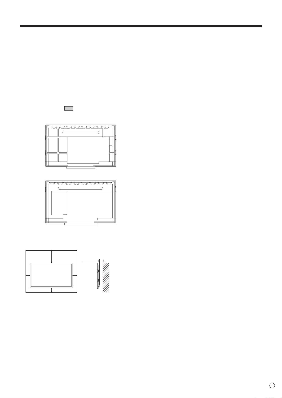
• Whenmovingthemonitor,besuretoholdthehandlesor
the parts marked by
below. Do not grasp the screen
or tray. This may cause product damage, failure, or injury.
[PN-C861H]
[PN-C751H]
• Thismonitorshouldbeusedatanambienttemperature
between 41°F (5°C) and 95°F (35°C). Provide enough
space around the monitor to prevent heat from
accumulating inside.
Unit: inch [mm]
7-7/8 [200]
2 [50]
2
[50]
2
[50]
1-7/16 [35]
• Ifitisdifficulttoprovidesufficientspaceforanyreason
such as the installation of the monitor inside a housing or
of several units side-by-side, or if the ambient temperature
may be outside of the range of 41°F (5°C) to 95°F (35°C),
install a fan or take other measures to keep the ambient
temperature within the required range.
• Temperatureconditionmaychangewhenusingthemonitor
together with the optional equipments recommended by
SHARP. In such cases, please check the temperature
condition specified by the optional equipments.
• Donotblockanyventilationopenings.Ifthetemperature
inside the monitor rises, this could lead to a malfunction.
• Donotplacethemonitoronadevicewhichgeneratesheat.
• Donotusetheproductinlocationswheretheunitis
exposed to direct sunlight or other strong light. Since this
product operates with infrared rays, such light may cause a
malfunction.
• Whenusingmultiplemonitorsclosely,besuretheinfrared
transmitter/receiver does not affect the other ones.

8
E
Contents
IMPORTANT INFORMATION ............................................ 3
DEAR SHARP CUSTOMER ..............................................4
SAFETY PRECAUTIONS ..................................................4
TIPS AND SAFETY INSTRUCTIONS ...............................6
MOUNTING PRECAUTIONS ............................................7
Supplied Components ..................................................... 9
System Requirements .....................................................9
Part Names .....................................................................10
Connecting Peripheral Equipment ...............................12
Connecting the Power Cord .........................................14
Binding Cables ............................................................... 14
Preparing the Remote Control Unit .............................. 15
Installing the batteries ................................................15
Remote control operation range .................................15
Turning Power On/Off .................................................... 16
Turning on the main power.........................................16
Turning power on/off ..................................................16
Basic Operation .............................................................17
About the home screen of APPLICATION mode ........ 17
Using the remote control unit .....................................18
Menu Items .....................................................................20
Displaying the menu screen ....................................... 20
Controlling the Monitor with a computer (RS-232C)
...21
Computer connection .................................................21
Communication conditions .........................................21
Communication procedure .........................................21
RS-232C command table ........................................... 23
Specifications ...............................................................25
Intellectual Property Rights and Other Matters ..........28
Mounting Precautions
(For SHARP dealers and service engineers) ............... 29
9
E
Hardware
Must have a USB 2.0 compliant port.
CD-ROM drive required for software installation.
Operating system
Windows 8.1 (32-bit or 64-bit version), Windows 10 (32-bit or 64-bit version)
macOS v10.13, v10.14
Google Chrome OS Version 74 or later
Requirements when the software (Windows) supplied with this monitor is used.
CPU
Intel Core i5-6360U or faster
Intel Core i7-6650U or faster recommended
Video Output Must be capable of output at a Vsync of 60 Hz or higher
Memory At least 4 GB
Free space on hard drive At least 5 GB (free space separately required for data storage)
To use the touch panel, connect the USB cable (supplied) to your computer.
The touch panel operates with the standard driver of each operating system. On the Mac, operation is only possible in mouse
mode.
Install Pen Software from the supplied CD-ROM.
When the Information Display Downloader is installed, you can check and download the most recent versions of the software
programs and operation manuals.
To install the software, see the manual for each.
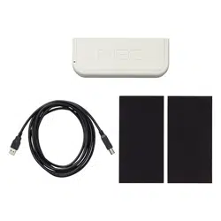
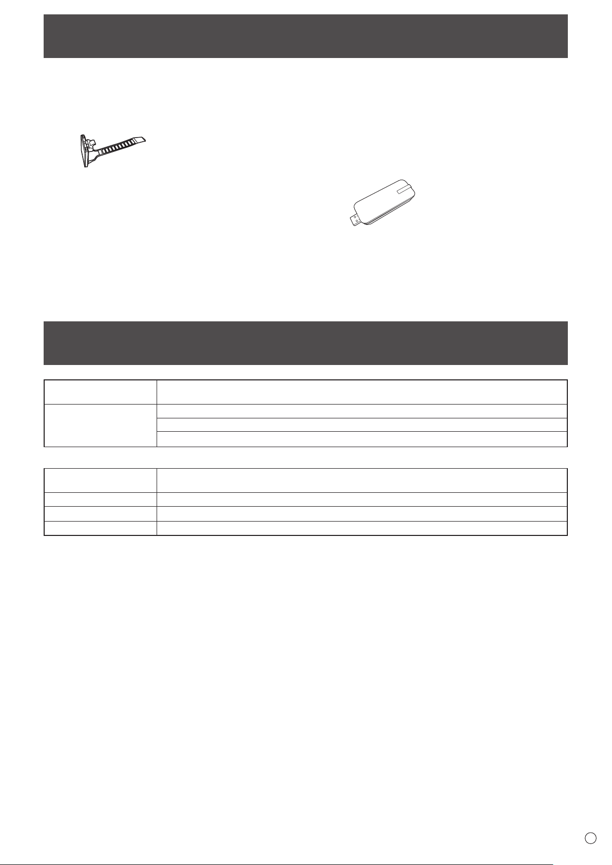
Supplied Components
If any component should be missing, please contact your dealer.
Liquid Crystal Display Monitor: 1
Remote control unit: 1
Cable clamp (affixing type): 3
Power cord: 1
Remote control unit battery: 2
CD-ROM (Utility Disk for Windows): 1
Setup Manual: 1
Touch pen: 2
Tray: 1
Tray mounting screws (M3x15): 5
USB cable: 1
Cover SHARP logo: 1
Place this sticker onto the SHARP logo to cover the logo.
Wireless Adapter: 1
* SHARP Corporation holds authorship rights to the Utility Disk program. Do not reproduce it without permission.
* For environmental protection!
Do not dispose of batteries in household waste. Follow the disposal instructions for your area.
System Requirements
10
E
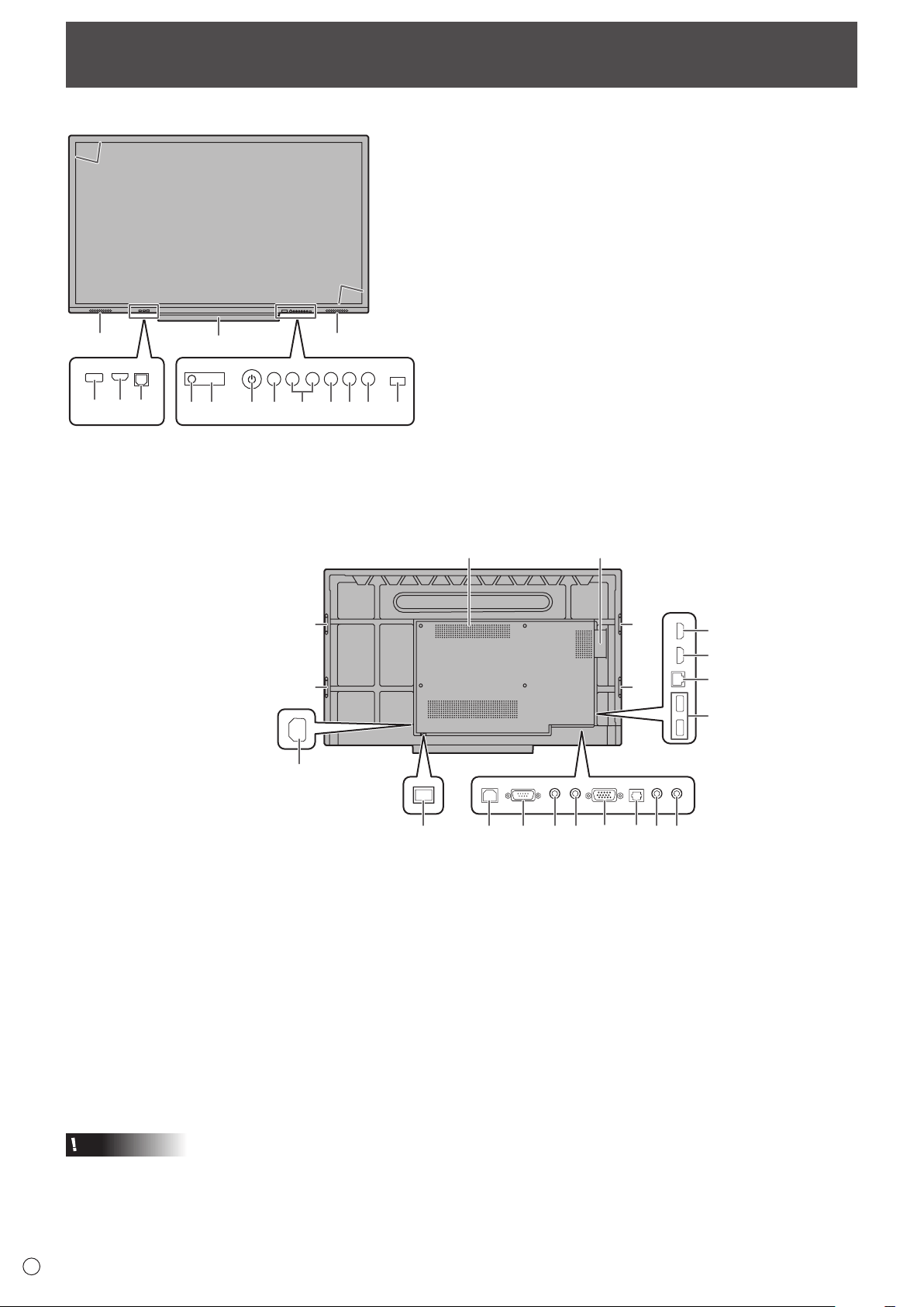
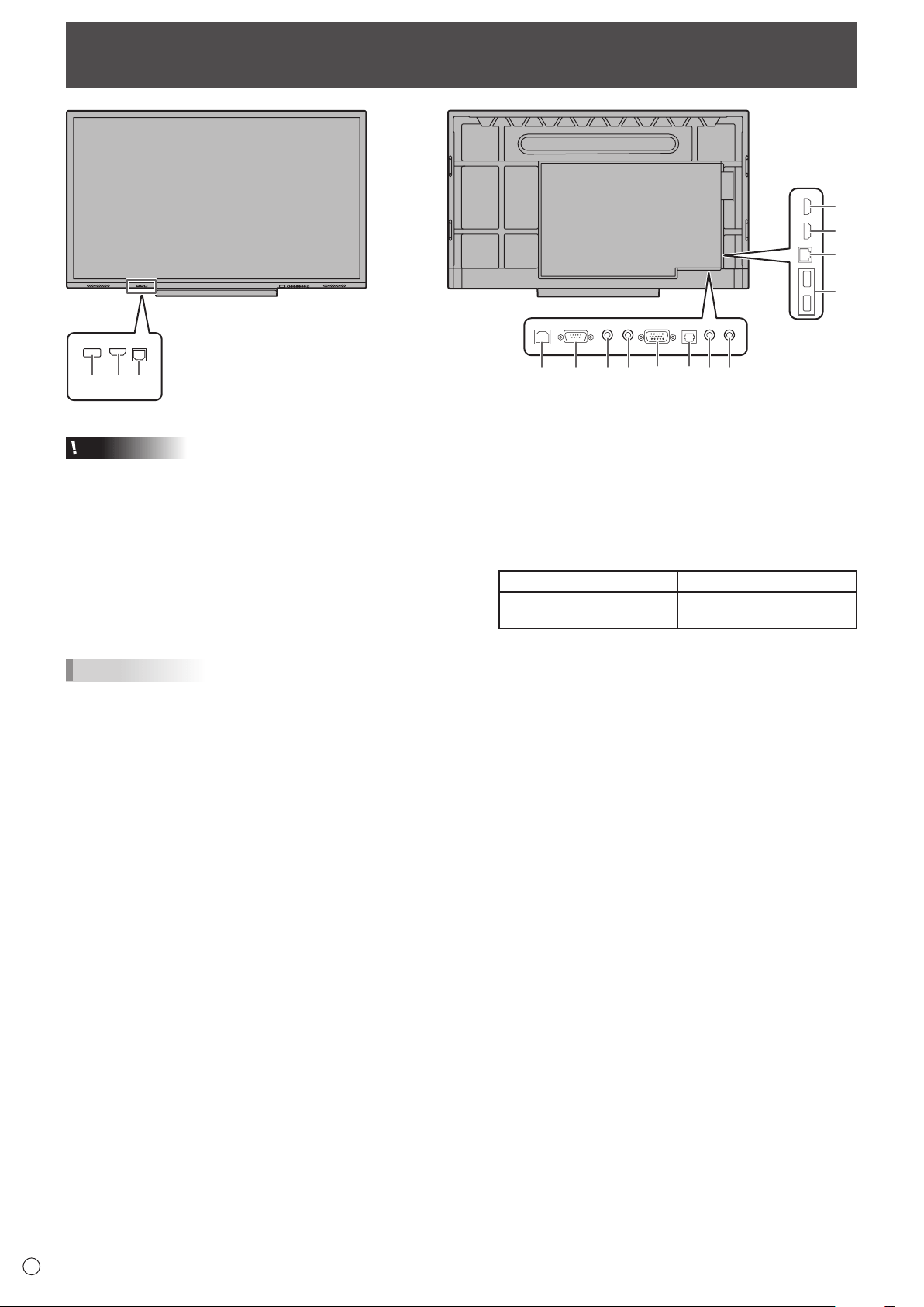
Part Names
n
Front view
15
1313
14
15
123
45 67 8910 11 12
1. USB port (USB 2.0 compliant) (See page 12.)
2. HDMI 1 input terminal (See page 12.)
3. TOUCH PANEL terminal 1 (for touch panel) (See page
12.)
4. Power LED (See page 16.)
5. Remote control sensor (See page 15.)
6. POWER button (See page 16.)
7. FREEZE button (See page 18.)
8. VOLUME +/- (Volume adjustment) buttons (See page
18.)
9. Touch On/Off button
Toggle the touch panel on and off. When turned off, only
this button and the POWER button can be used.
10. MENU button (See page 19.)
11. INPUT button (See page 19.)
12. Brightness sensor
13. Speakers
14. Tray
15. Infrared transmitter/receiver
Caution
• ConsultyourSHARPdealerforattachment/detachmentofoptionalparts.
16. HDMI 3 input terminal (See page 12.)
17. HDMI 2 input terminal (See page 12.)
18. LAN terminal (See page 12.)
19. USB ports (USB 2.0 compliant) (See page 12.)
20. TOUCH PANEL terminal 2 (for touch panel) (See page
12.)
21. RS-232C input terminal (See page 13.)
22. Audio output terminal (See page 13.)
23. Audio input terminal (See page 13.)
24. D-sub input terminal (VGA) (See page 13.)
25. Digital audio output (optical) terminal (See page 13.)
26. Mini AV input terminal (See page 13.)
27. Mini Component input terminal (YPBPR) (See page
13.)
28. Main power switch (See page 16.)
29. AC input terminal (See page 14.)
30. Handles
31. Handles (PN-C861H)
32. Expansion slot (OPS)
This section is used to connect optional hardware for
function expansion. Offering this attachment location
is not a guarantee that future compatible hardware
attachments will be released.
33. Vents
n
Rear view
33 32
30
31
30
31
16
17
18
19
20
28
29
21 22 23 24 25 26 27
11
E
Part Names
n
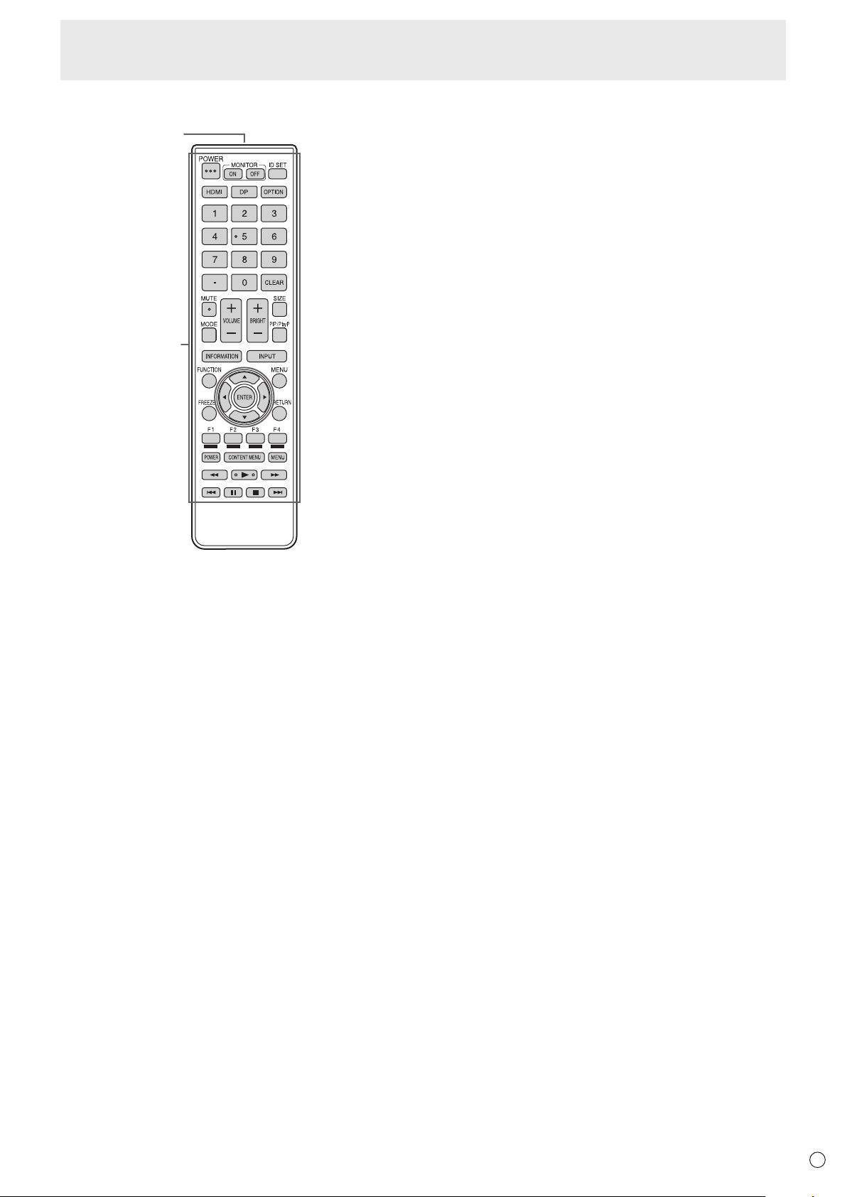
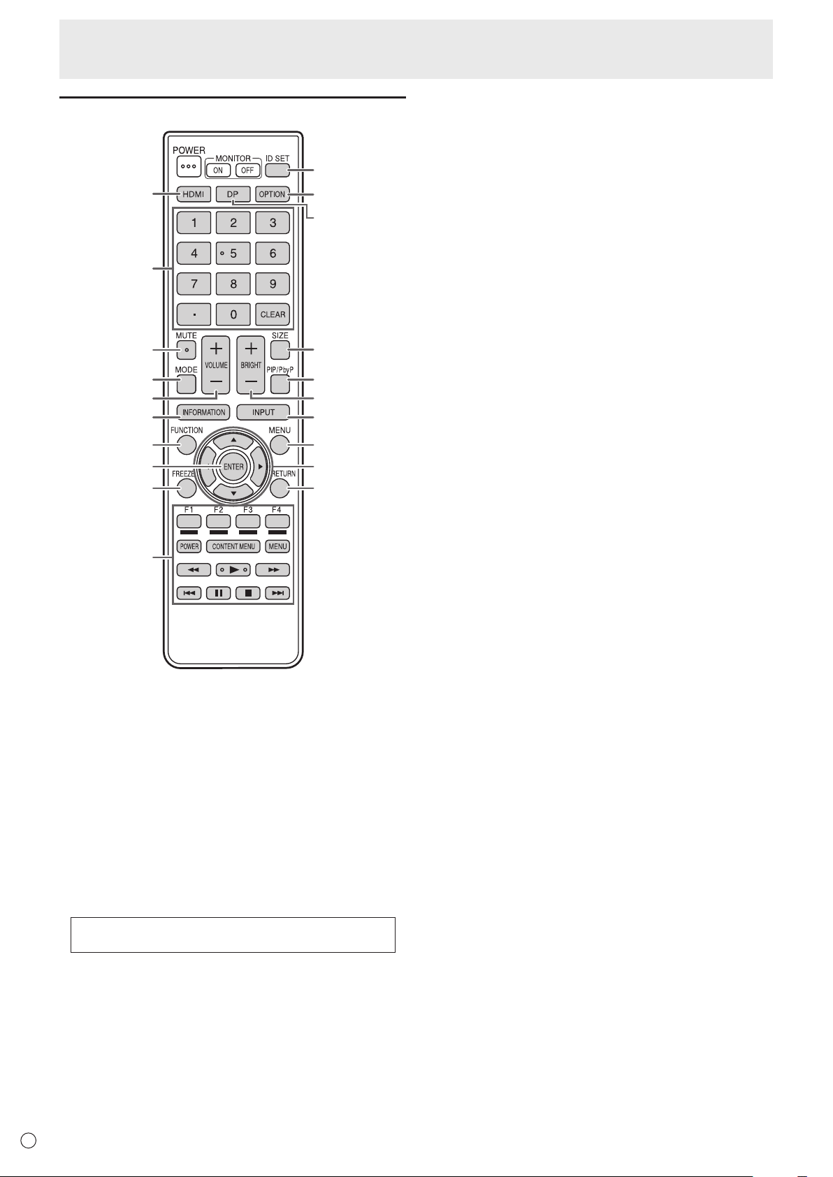
Remote control unit
2
1
1. Signal transmitter
2. Operation buttons (See page 18.)
12
E
123
4
5
6
1
7 8910 11 12 13 14
Connecting Peripheral Equipment
Caution
• Besuretoturnoffthemainpowerswitchanddisconnect
the plug from the power outlet before connecting/
disconnecting cables. Also, read the manual of the
equipment to be connected.
• Becarefulnottoconfusetheinputterminalwiththeoutput
terminal when connecting cables. Accidentally reversing
cables connected to the input and output terminals may
cause malfunctions and other problems.
• Donotuseanycablethathasadamagedordeformed
terminal. Using such cables may cause malfunctions.
TIPS
• Whenusingthetouchpanel,connecttheUSBcabletothe
computer.
• Imagesmaynotbedisplayedproperlydependingonthe
computer (video card) to be connected.
• Usetheautomaticscreenadjustmentwhenacomputer
screen is displayed for the first time using VGA (D-SUB) or
when the setting of the computer is changed. The screen
is adjusted automatically using Auto Adjust in PC Setting of
the Picture menu.
• Iftheaudiooutputfromtheplaybackdeviceisconnected
directly to speakers or other devices, the video on the
monitor may appear delayed from the audio portion.
Audio should be played through this monitor by connecting
the playback device to the monitor’s audio input, and
connecting the monitor’s audio output to the speakers or
other devices.
1. USB ports (USB 2.0 compliant) (5V, 500mA)
• ConnectaUSBflashdrivetotheUSBport.
• DonotconnectaUSBdeviceotherthanaUSBflash
drive.
• BeforeremovingaUSBflashdrive,followthestepsfor
removal. (See page 13.)
Supported USB flash drives
File System FAT32
Capacity
Up to 32 GB
(maximum file size 4 GB)
• DonotuseaUSBflashdrivewithasecurityfunctionor
a write protection function.
• UseaUSBflashdrivewithashapethatcanbeinserted
in the USB port. Some USB flash drives with special
shapes cannot be inserted. Do not forcibly insert a USB
flash drive. This may damage the connector and cause
failure.
2. HDMI 1 input terminal
• UseacommerciallyavailableHDMIcable(conformingto
the HDMI standard) that supports 4K.
• ThisterminaldoesnotsupportHDMICEC.
3. TOUCH PANEL terminal 1 (for touch panel)
• Tousethetouchpanelwithacomputer,connectthe
touch panel to the computer with a USB cable.
• Tousethisterminal,connectyourcomputertotheHDMI
1 input terminal on the front of the monitor.
4. HDMI 3 input terminal
5. HDMI 2 input terminal
• UseacommerciallyavailableHDMIcable(conformingto
the HDMI standard) that supports 4K.
6. LAN terminal
• WhenPowerSaveModeisOff,youcanconnecttoa
network and use the Wake on LAN function.
7. TOUCH PANEL terminal 2 (for touch panel)
• Tousethetouchpanelwithacomputer,connectthe
touch panel to the computer with a USB cable.
• Tousethisterminal,connectyourcomputertothevideo
input terminal on the rear of the monitor.
13
E
Connecting Peripheral Equipment
8. RS-232C input terminal
• You can control the monitor from a computer by
connecting a commercially available RS-232 straight
cable between these terminals and the computer. The
terminal on the monitor is a female-type connector.
9. Audio output terminal
• The output sound varies depending on the input mode.
10. Audio input terminal
• Use an audio cable without resistance.
11. D-sub input terminal (VGA)
12. Digital audio output (optical) terminal
• Audio that is input into the monitor is output.
• Connect using a commercially available audio digital
cable.
• The output sound varies depending on the input mode.
• You can adjust the volume with volume adjustment.
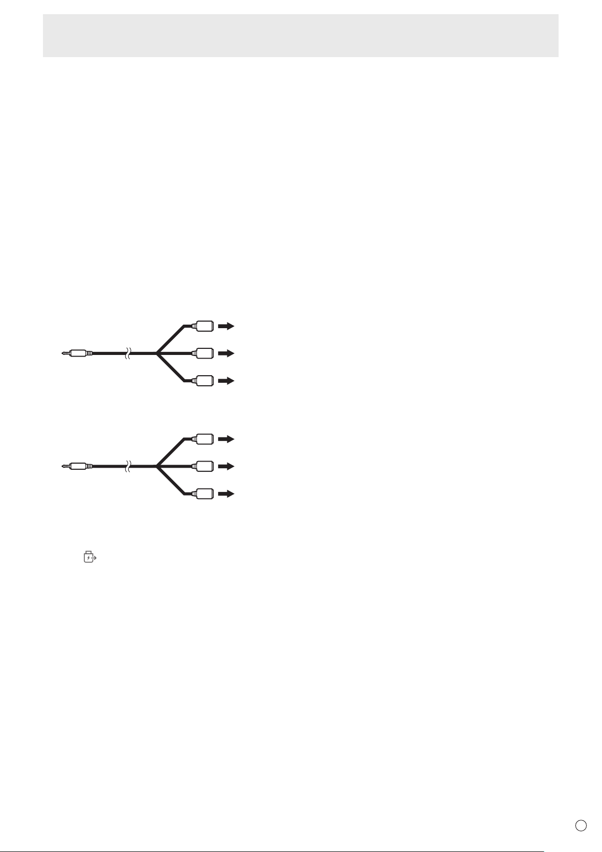
13. Mini AV input terminal
• Change the input mode to AV.
• A conversion cable must be purchased separately.
Video
Audio (L)
Audio (R)
14. Mini Component input terminal (YPBPR)
• Change the input mode to YPBPR.
• A conversion cable must be purchased separately.
Y
Pb/Cb
Pr/Cr
How to remove a USB flash drive
1. Start File Explorer. (See page 17.)
2. Touch
of the device you want to unmount.
14
E
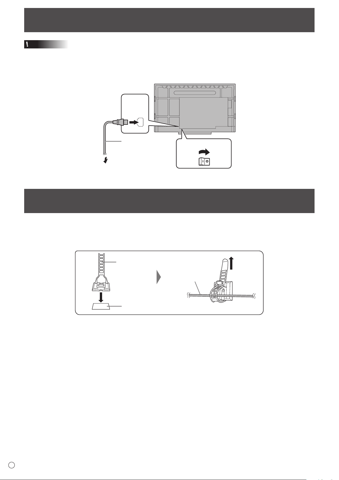
Connecting the Power Cord
Caution
• Useonlythepowercordsuppliedwiththemonitor.
1. Turn off the main power switch.
2. Plug the power cord (supplied) into the AC input terminal.
3. Plug the power cord (supplied) into the power outlet.
AC input
terminal
Main power switch
1
2
For power outlet
3
Power cord (Supplied)
Binding Cables
The supplied cable clamps can be used to clamp the power cord and cables connected to the back of the monitor.
Attach the supplied cable clamps (affixing type) to a flat surface, removing any dust or dirt before attaching.
Do not attach over a vent.
Cable clamp
(affixing type)
Affixing point
Cable
15
E
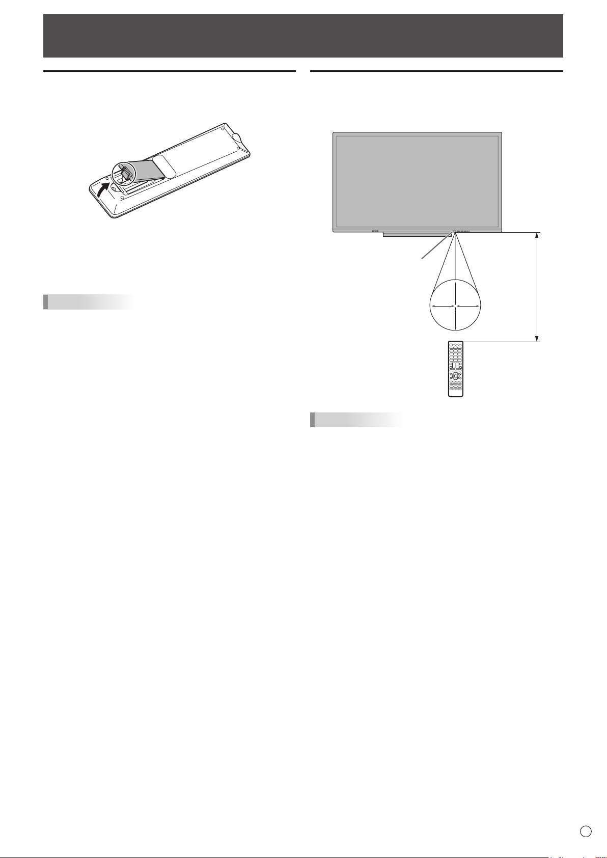
Preparing the Remote Control Unit
Remote control operation range
The operation range of the remote control unit is approx. 16.4
feet (5 m) at an angle of approx 10° from the center to the top/
bottom/right/left of the remote control sensor.
10
°1
0°
10°
10°
Remote
control sensor
16.4
feet
(5 m)
TIPS
• Donotexposetheremotecontrolunittoshockbydropping
orsteppingonit.Thiscouldleadtoamalfunction.
• Donotexposetheremotecontrolunittoliquids,anddonot
placeitinanareawithhighhumidity.
• Theremotecontrolunitmaynotworkproperlyiftheremote
controlsensorisunderdirectsunlightorstronglighting.
• Objectsbetweentheremotecontrolunitandtheremote
controlsensormaypreventproperoperation.
• Replacethebatterieswhentheyrunlowasthismay
shorten the remote control’s operation range.
• Ifafluorescentlightisilluminatedneartheremotecontrol
unit,itmayinterferewithproperoperation.
• Donotuseitwiththeremotecontrolofotherequipment
suchasairconditioner,stereocomponents,etc.
Installing the batteries
1. Placeyourfingeronthepartmarkedwiththe▲,and
then pull the cover off.
2. See the instructions in the compartment and put in the
batteries (R03 or LR03 (“AAA” size) x 2) with their plus
(+) and minus (-) sides oriented correctly.
3. Close the cover.
TIPS
• Whenthebatteriesbecomeexhausted,replacethemwith
new(commerciallyavailable)batteries.
• Thesuppliedbatteriesmaybecomeexhaustedquickly
dependingonhowtheyarestored.
• Ifyouwillnotbeusingtheremotecontrolforalongtime,
removethebatteries.
• Usemanganeseoralkalinebatteriesonly.
16
E
Caution
• Turnonthemonitorfirstbeforeturningonthecomputeror
playback device.
• WhenswitchingthemainpowerswitchorthePOWER
button off and back on, always wait for at least 5 seconds.
A short interval may result in a malfunction.
Turning on the main power
Main power switch
When you turn on the main power, the monitor enters standby
mode.
Caution
• Themainpowermustbeturnedon/offwiththemainpower
switch. Do not connect/disconnect the power cord or turn
the breaker on/off while the main power switch is on.
• Foracompleteelectricaldisconnection,pulloutthemain
plug.
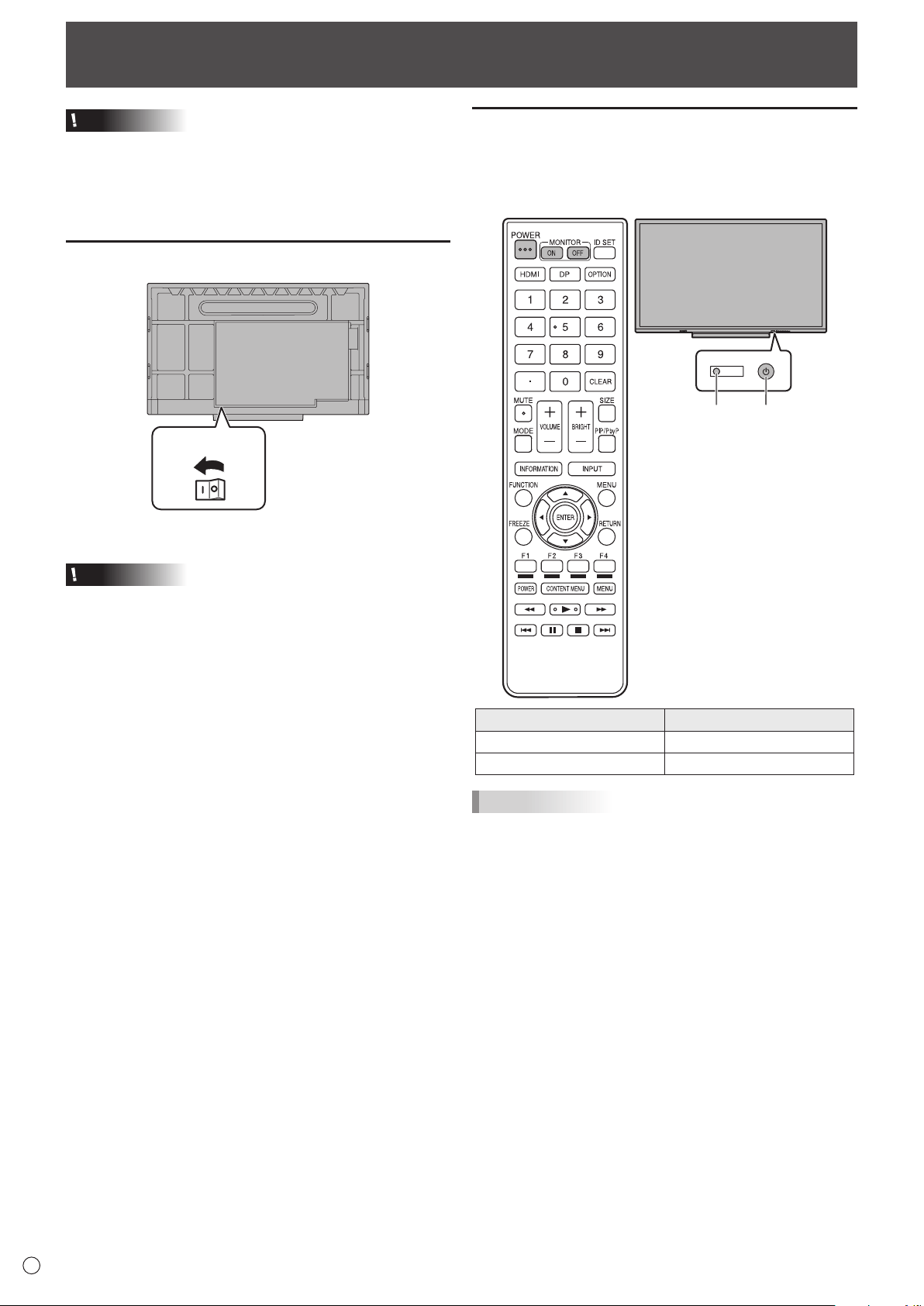
Turning Power On/Off
Turning power on/off
Press the POWER button to turn the power ON/OFF.
You can also turn the power ON/OFF by pressing the
MONITOR ON button/MONITOR OFF button on the remote
control unit.
Power LED
POWER button
Status Status of the monitor
Blue lit Power on
Red lit Power off (Standby mode)
TIPS
• Whenthemonitoristurnedonforthefirsttimeafterbeing
shipped from the factory, the settings screen appears. In
some cases it may take time for the settings screen to
appear, however, continue waiting until the screen appears.
• Whenthemainpowerswitchisoff,themonitorcannotbe
turned on.
17
E
Basic Operation
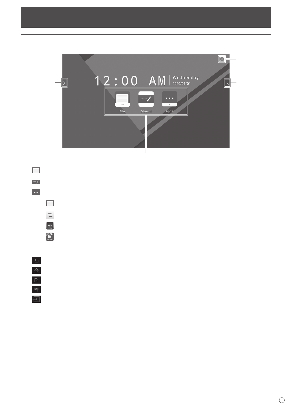
About the home screen of APPLICATION mode
This appears when the input mode is changed to APPLICATION.
(1)
(2)
(3)
(2)
(1) Start File Explorer.
Start E-board.
Display the list of applications.
Start File Explorer.
Display the side menu.
Start E-board.
Start EShareServer.
(2) Touch to display the settings menu.
Go back to the previous screen.
Return to the home screen of APPLICATION mode.
Start Note.
Display the side menu.
Display the change input menu.
(3) Display the menu of system-related settings.
18
E
Using the remote control unit
1
2
3
4
5
6
7
8
9
10
11
12
13
14
15
16
17
18
19
20
1. HDMI
Switch the input mode to HDMI 1, HDMI 2 or HDMI 3.
2. Numeric input buttons
These buttons are used for setting such as LAN setting.
3. MUTE
Turns off the volume temporarily.
Press the MUTE button again to turn the sound back to the
previous level.
4. MODE (Display mode selection)
In video input mode (other than APPLICATION), each time you
press this button, the picture mode changes in the following
order:
STD(Standard)→Vivid→HighIlluminance→STD...
• HighIlluminanceisadisplaywithcolorssuitedtobright
locations.
5. VOLUME +/- (Volume adjustment)
Press+or-toadjustthevolume.
6. INFORMATION
In video input mode (other than APPLICATION), use this to
display the input terminal and the signal.
7. FUNCTION
Use this to display the Function menu. Press the FUNCTION
button, and then press the MENU button within 10 seconds.
8. ENTER
Confirms the setting.
9. FREEZE
Freezes the video shown on the monitor.
To cancel, press any button other than the POWER button,
MUTE button or VOLUME button.
In some cases a residual image may occur. Do not freeze the
video for a long time.
10. Buttons for playing the files or operating the HDMI-
connected device
When used for playing the files, the buttons that can be used
vary depending on the file that is played.
When HDMI CEC is set to On, only the POWER button is
enabled for the device connected through the HDMI interface.
11. ID SET
This is not used with this monitor.
12. OPTION
Switch the input mode to APPLICATION or OPS.
13. DP (DisplayPort)
This is not used with this monitor.
14. SIZE (Screen size selection)
In video input mode (other than APPLICATION), each time
you press this button, screen size is changed.
15. PIP/PbyP
This is not used with this monitor.
16. BRIGHT +/- (Brightness adjustment)
Press+or-toadjustthebrightness.
Basic Operation
19
E
Basic Operation
17. INPUT (Input mode selection)
The menu is displayed.
Press the
or button to select the input mode, and press
the ENTER button to enter.
Input mode Video Audio
APPLICATION APPLICATION
APPLICATION
HDMI 1
HDMI 1 input
terminal
HDMI 1 input
terminal
HDMI 2
HDMI 2 input
terminal
HDMI 2 input
terminal
HDMI 3
HDMI 3 input
terminal
HDMI 3 input
terminal
VGA D-sub input terminal Audio input terminal
AV
Mini AV input
terminal
Mini AV input
terminal
YPBPR
Mini Component
input terminal
Audio input terminal
OPS Expansion slot Expansion slot
18. MENU
Displays the menu screen. (See page 20.)
19. Cursor
These buttons are used to perform operations such as
selecting items, changing adjustment values, and moving the
cursor.
20. RETURN
Returns to the previous screen.
20
E
Menu Items
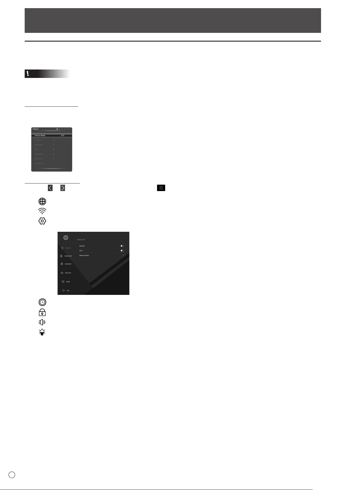
Displaying the menu screen
Video and audio adjustment and settings of various functions are enabled.
Caution
• Donotturnthemainpowerswitchoffwhilethemenuitemsarebeingdisplayed.Doingsomayinitializethesettings.
n
How to display the menu
Display a video menu
1. Change to a video input mode (other than APPLICATION).
2. Press the MENU button.
Themenuwillbedisplayed.
Display the side menu
1. Touch
or on the side of the screen, and touch .
•
: EnableordisableLAN(Ethernet)connection.
•
: EnableordisablewirelessLANconnection.
•
: Displaythesystemsettingsmenu.
IntheAPPLICATIONmode,youcanalsopresstheMENUbuttontodisplaythemenu.
•
: Youcanusethetimer/stopwatch.Setatimetouseasatimer.
•
: Lockthescreen.Double-clicktounlock.Youcansetapasswordforunlockingthescreen.
•
: Adjustthevolume.
•
: Adjustthebrightness.SelectAutotoautomaticallyadjustthescreenbrightnessaccordingtolightingconditions
andthesurroundingbrightness.
21
E
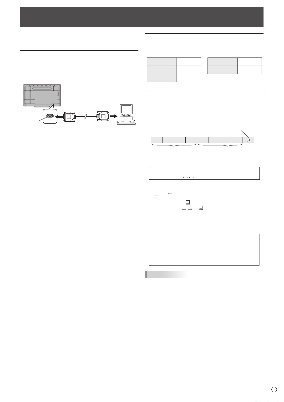
Controlling the Monitor with a computer (RS-232C)
You can control this monitor from a computer via RS-232C
(COM port) on the computer.
Computer connection
Connect with RS-232 straight cable between the computer’s
COM port (RS-232C connector) and the RS-232C input
terminal on the monitor. The terminal on the monitor is a
female-type connector.
RS-232 straight cable
(commercially available)
To COM port
Computer
RS-232C
input terminal
Communication conditions
Set the RS-232C communication settings on the computer to
match the monitor’s communication settings as follows:
Baud rate 9600bps
Stop bit
1 bit
Data length 8 bits Flow control None
Parity bit None
Communication procedure
n
Command format
When a command is sent from the computer to the monitor,
the monitor operates according to the received command and
sends a response message to the computer.
C1 C2 C3 C4 P1 P2 P3 P4
Return code
Command field
(4 prescribed
alphanumerical characters)
Parameter field
(4 character string comprised of:
0-9, space, ?)
Example: VOLM0030
VOLM
30
* Be sure to input 4 characters for the parameter. Pad with
spaces (“
”) if necessary.
(“
” is a return code (0D
H
, 0A
H
or 0D
H
))
Wrong : VOLM30
Right : VOLM 30
If a command has “R” listed for “Direction” in the
“RS-232C command table” on page 23, the current value can
be returned by using “?” as the parameter.
Example:
VOLM ? ? ? ? ←
From computer to monitor (How
much is current volume setting?).
30 ←
From monitor to computer
(Current volume setting: 30).
TIPS
• SendCommandfield,ParameterfieldandReturncode
at the same time. When sending a command manually in
1 character units and it takes more than 2 seconds, the
command function does not work.
22
E
Controlling the Monitor with a computer (RS-232C)
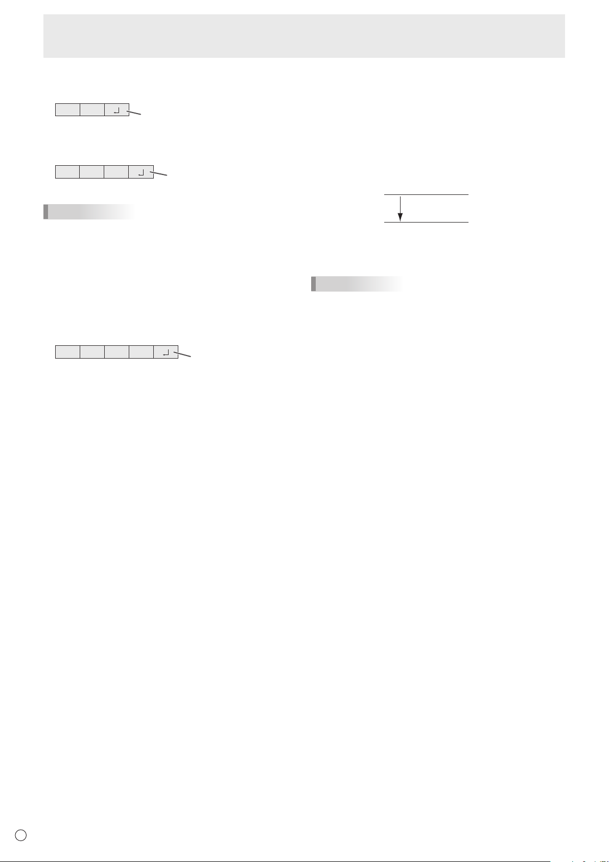
n
Response code format
When a command has been executed correctly
O K
Return code
(0DH, 0AH)
A response is returned after a command is executed.
When a command has not been executed
R R E
Return code
(0DH, 0AH)
TIPS
• “ERR” is returned when there is no relevant command or
when the command cannot be used in the current state of
the monitor.
• Ifcommunicationhasnotbeenestablishedforreasons
such as a bad connection between the computer and
monitor, nothing is returned (not even ERR).
•
“ERR” may be returned when a command cannot be received
correctly due to interference from the surrounding environment.
Please ensure that the system or software resends the
command if this occurs.
If execution of the command is taking some time
I W T A
Return code
(0DH, 0AH)
When the following commands are used, “WAIT” is returned.
In this case, a value will be returned if you wait a while. Do not
send any command during this period.
• CommandswhichreturnWAIT:
RSET, POWR, INPS, WIDE, BOMD
n
Communication interval
• AfterOKorERRisreturned,youmustsendthefollowing
commands.
To set a timeout for the command response, specify 10
seconds or longer.
• Provideanintervalof100msormorebetweenthe
command response and the transmission of the next
command.
VOLM0020
OK
INPS0002
WAIT
OK
Interval of 100 ms or more
TIPS
• WhenALLRESETisexecuted,themonitorentersstandby
mode. Wait at least 1 minute before sending the next
command. If you execute power “On” after ALL RESET, it
will take time for the monitor to start up, so wait at least 5
minutes before sending the next command.
• Beforesendingapower“On”or“Off”command,itis
recommended that you perform buffer clear at the sending
application side.
• Afterexecutingapower“On”or“Off”command,waitat
least 1 minute before sending the next command.
23
E
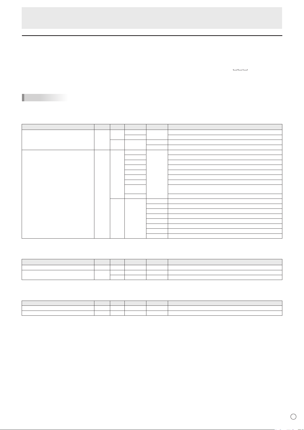
RS-232C command table
How to read the command table
Command: Command field (See page 21.)
Direction: W When the “Parameter” is set in the parameter field (see page 21), the command functions as described
under “Control/Response Contents”.
R The returned value indicated under “Reply” can be obtained by setting “????” or “
?” in the
parameter field. (See page 21.)
Parameter: Parameter field (See page 21.)
Reply: Response (Returned value)
TIPS
• Inthestandbymode,theonlycommandthatisusedisPowercontrol.
Power control/Input mode selection
Function
Command Direction
Parameter Reply Control/Response contents
Powercontrol POWR W 0
Switchestostandbymode.
1 Returns from standby mode.
R 0 Standby mode
1 Normal mode
Input mode selection INPS W 0 Toggle change for input mode.
2 VGA
3 YPBPR
4 AV
10 HDMI 1
13 HDMI 2
18 HDMI 3
21 OPS
“ERR”whennothingisattachedintheexpansionslot.
24 APPLICATION
R 2 VGA
3 YPBPR
4 AV
10 HDMI 1
13 HDMI 2
18 HDMI 3
21 OPS
24 APPLICATION
Picture menu
Function
Command Direction
Parameter Reply Control/Response contents
BRIGHT VLMP WR 0-100 0-100 “ERR”whenAutoandEnergySavingareineffect.
SIZE (Screen size selection) WIDE W 0 0 Toggle change for input mode.
WR 1-5 1-5 1: 16:9, 2: Dot by Dot, 3: 4:3, 4: Zoom1, 5: Zoom2
Sound menu
Function
Command Direction
Parameter Reply Control/Response contents
VOLUME VOLM WR 0-100 0-100
MUTE AUDIO MUTE WR 0-1 0-1 0: OFF, 1: ON
Controlling the Monitor with a computer (RS-232C)
24
E
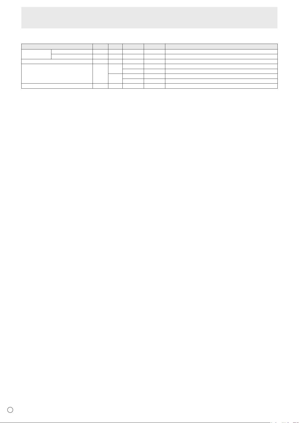
Others
Function
Command Direction
Parameter Reply Control/Response contents
INFORMATION Model INF1 R Value
Serial no. SRNO R Value
ALL RESET RSET W 0 ALL RESET
BACKLIGHT OFF BOMD W 0 Turn backlight off
1 Turn backlight on
R 0 Backlight off
1 Backlight on
Check the resolution PXCK R - Returns current resolution in the form of hhh, vvv.
Controlling the Monitor with a computer (RS-232C)
25
E
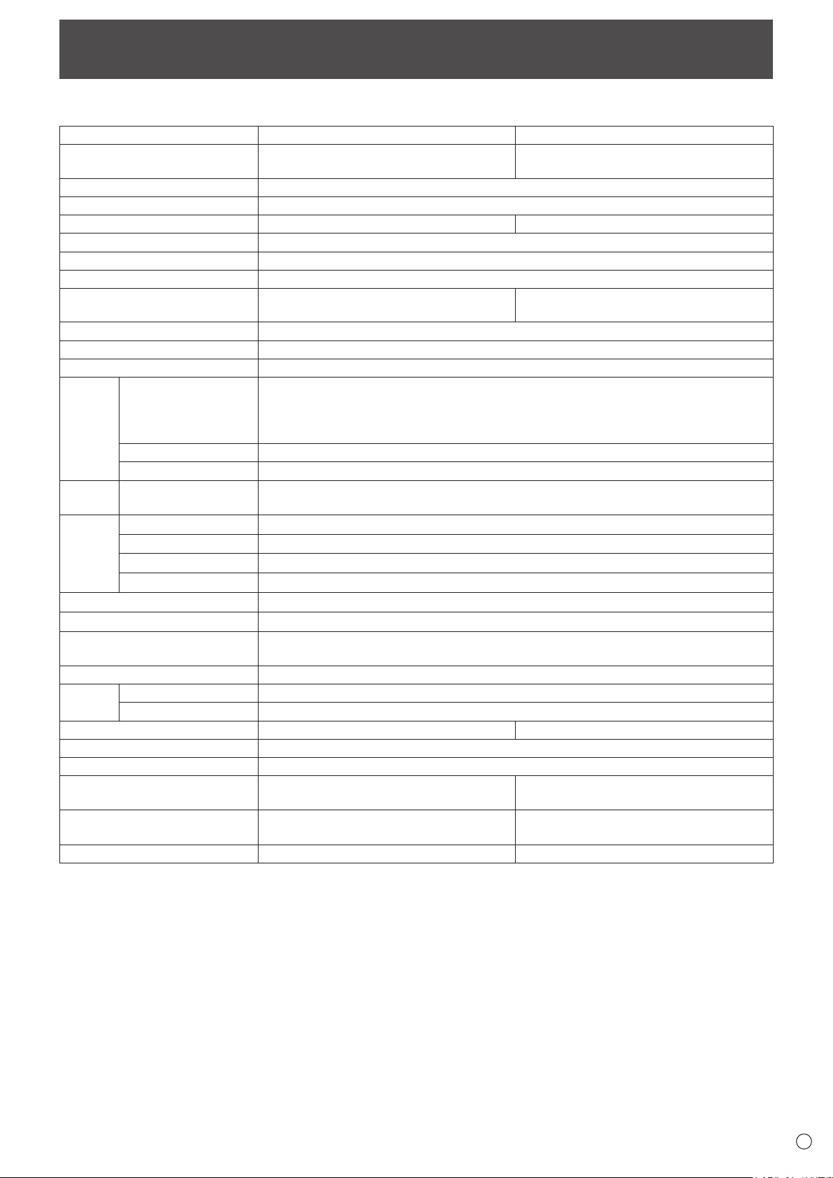
Specifications
n
Product Specifications
Model
PN-C861H PN-C751H
LCD component
86" Class
[85-9/16 inch (217.4 cm) diagonal] TFT LCD
75" Class
[74-1/2 inch (189.3 cm) diagonal] TFT LCD
Max. resolution (pixels)
3840 x 2160
Max. colors
Approx. 1.07 billion colors
Pixel pitch
0.4935 mm (H) × 0.4935 mm (V) 0.4296 mm (H) × 0.4296 mm (V)
Brightness (typical) 400 cd/m
2
*
1
Contrast ratio (typical) 1200: 1
Viewing angle
178° right/left/up/down (contrast ratio ≥ 10)
Screen active area inch (mm)
74-5/8 (W) x 41-15/16 (H)
(1895.0 x 1066.0)
64-15/16 (W) x 36-9/16 (H)
(1649.7 x 927.9)
Computer input signal
Analog RGB (0.7 Vp-p) [75 Ω]
Sync signal
Horizontal/vertical separate (TTL: positive/negative)
Plug and play
VESA DDC2B
Input
terminals
Video Mini D-sub 15 pin, 3 rows x 1
HDMI x 3
Mini AV in x 1
Mini YPbPr x 1 (Component)
Audio 3.5 mm mini stereo jack x 1
Serial (RS-232C)
D-sub 9 pin x 1
Output
terminals
Audio
3.5 mm mini stereo jack x 1
Digital audio output (optical) x 1
System CPU Arm Cortex - A53 processor (quad core)
Memory 1GB
Storage 8GB
LAN terminal 10BASE-T/100 BASE-TX (Wake on LAN only)
Wireless LAN IEEE802.11ac/n/a/g/b compliant (When a wireless adapter is connected)
USB 2.0 compliant (Type A) x 3
Expansion slot 19 V, 4.74 A
(power supplied when expanding the functions with an optional part)
Speaker output 10 W + 10 W
Touch
Panel
Detection method Infrared blocking detection method
Computer connector USB (2.0 compliant) (Type B) x 2
Power requirement AC 100 - 240 V, 5.9 A, 50/60 Hz AC 100 - 240 V, 5.2 A, 50/60 Hz
Operating temperature
*
2
*
3
41°F to 95°F (5°C to 35°C)
Operating humidity
*
3
20% to 80% (no condensation)
Power consumption
*
4
(standby mode
*
5
)
530 W (0.5 W) 460 W (0.5 W)
Dimensions inch (mm)
(excluding protrusions)
Approx. 78-1/4 (W) x 4-7/16 (D) x 46-1/4 (H)
(1988 x 113 x 1175)
Approx. 68-5/16 (W) x 4-1/8 (D) x
40-13/16 (H) (1735 x 105 x 1036)
Weight lbs. (kg)
Approx. 176.4 (80) Approx. 134.5 (61)
*1 Brightness will depend on input mode and other picture settings. Brightness level will decrease over time. Due to the nature of the
equipment, it is not possible to precisely maintain a constant level of brightness. This is the brightness of the LCD panel, not the
brightness of the product.
*2 Temperature condition may change when using the monitor together with the optional equipments recommended by SHARP. In such
cases, please check the temperature condition specified by the optional equipments.
*3 In addition, check the requirements of the computer and other devices to be connected, and make sure that all requirements are satisfied.
*4 When an option is installed in the expansion slot. When an option is not installed, PN-C861H: 420 W, PN-C751H: 360 W.
*5 When Power Save Mode is set to On.
When Power Save Mode is set to Off, and no optional part is attached: 2.0 W
As a part of our policy of continuous improvement, SHARP reserves the right to make design and specification changes for product improvement
without prior notice. The performance specification figures indicated are nominal values of production units. There may be some deviations from
these values in individual units.
26
E
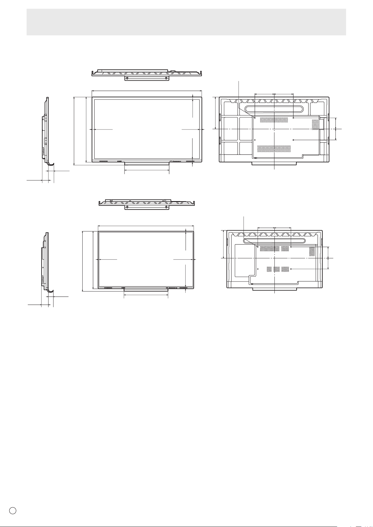
Specifications
n
Dimensional Drawings
Note that the values shown are approximate values.
Unit: inch [mm]
Screw holes for mounting brackets
3-11/16
[94]
4-7/16
[113]
78-1/4 [1988]
31-3/4 [806]
13-3/4
[350]
13-3/4
[350]
8
[202.5]
7-3/4
[197.5]
1-5/8 [41]
11/16 [18]
46-1/4 [1175]
48-3/8 [1228]
11/16 [18]
22-13/16 [579.5]
11/16 [18]
[PN-C861H]
[PN-C751H]
Screw holes for mounting brackets
3-11/16
[93]
4-1/8
[105]
68-5/16 [1735]
31-3/4 [806]
11-13/16
[300]
11-13/16
[300]
8-1/4
[210]
7-1/2
[190]
1-5/8 [41]
11/16 [18]
40-13/16 [1036]
42-7/8 [1089]
11/16 [18]
19-15/16 [506.5]
11/16 [18]
When mounting the monitor, be sure to use a wall-mount bracket that complies with the VESA-compatible mounting method.
SHARP recommends using M8 screws and tighten the screws.
Note that screw hole depth of the monitor is 1/2 inch (12 mm). Loose mounting may cause the product to fall, resulting in serious
personal injuries as well as damage to the product. The screw and hole should come together with over 3/8 inch (10 mm) length
of thread. Use a bracket which has been approved for UL1678 standard, and which can endure at least 4 times or more the
weight of the monitor.

27
E
n
Channels that can be used in wireless LAN
Standard Channel
Frequency band
(center frequency)
IEEE802.11 b/g/n 1-11ch 2412-2462MHz
IEEE802.11 ac/a/n
36/40/44/48ch 5180-5240MHz
52/56/60/64ch 5260-5320MHz
100/104/108/112/116/132/136/140ch 5500-5700MHz
149/153/157/161/165ch 5745-5825MHz
This device is restricted to indoor use due to its operation in the 5.15 GHz to 5.25 GHz frequency range. FCC requires this product to be used
indoors for frequency range 5.15 GHz to 5.25 GHz to reduce the potential for harmful interference to co-channel Mobile Satellite systems.
High power radars are allocated as primary users of the 5.25 GHz to 5.35 GHz and 5.65 GHz to 5.85 GHz bands. These radar stations can
cause interference with and/or damage this device.
Specifications

28
E
n
Information on the software license for this product
Software composition
The software included in this product is comprised of various software components whose individual copyrights are held by
SHARP or by third parties.
Software developed by SHARP and open source software
The copyrights for the software components and various relevant documents included with this product that were developed or
written by SHARP are owned by SHARP and are protected by the Copyright Act, international treaties, and other relevant laws.
This product also makes use of freely distributed software and software components whose copyrights are held by third parties.
These include software components covered by a GNU General Public License (hereafter GPL), a GNU Lesser General Public
License (hereafter LGPL) or other license agreement.
Obtaining source code
Some of the open source software licensors require the distributor to provide the source code with the executable software
components. GPL and LGPL include similar requirements. For information on obtaining the source code for the open source
software and for obtaining the GPL, LGPL, and other license agreement information, visit the following website:
https://jp.sharp/business/lcd-display/support/download/source_e.html
We are unable to answer any questions about the source code for the open source software. The source code for the software
components whose copyrights are held by SHARP is not distributed.
Intellectual Property Rights and Other Matters
29
E
• Wheninstalling,removingormovingthemonitor,ensurethatthisiscarriedoutbyatleast4people.
• Besuretouseawall-mountbracketdesignedordesignatedformountingthemonitor.
• Thismonitorisdesignedtobeinstalledonaconcretewallorpillar.Reinforcedworkmightbenecessaryforsomematerials
such as plaster / thin plastic board / wood before starting installation.
• Thismonitorandbracketmustbeinstalledonawallwhichcanendureatleast4timesormoretheweightofthemonitor.
Install by the most suitable method for the material and the structure.
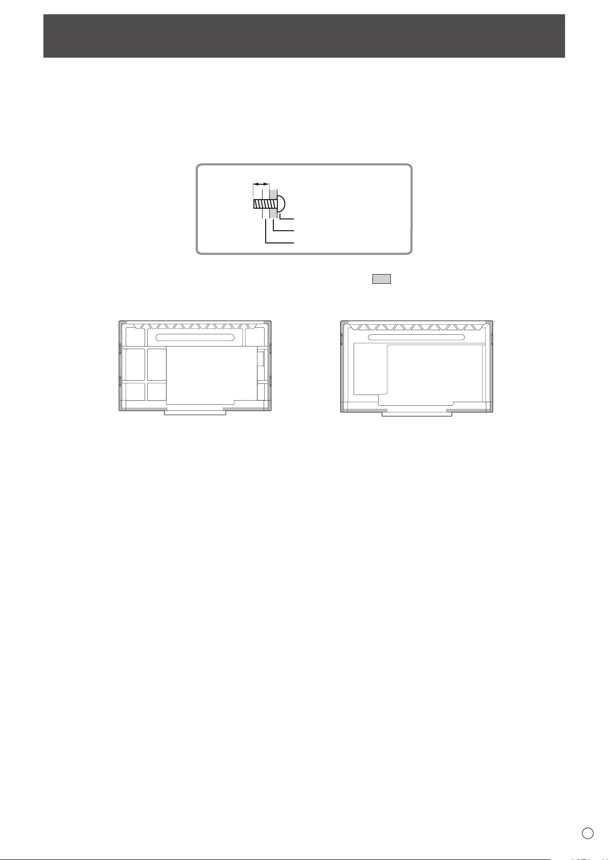
• ToattachaVESA-compliantmountingbracket,useM8screwsthatare3/8inch(10mm)to1/2inch(12mm)longerthanthe
thickness of the mounting bracket.
Screws (M8)
Mounting bracket
Monitor mounting
3/8 - 1/2 inch (10-12 mm)
• Donotuseanimpactdriver.
• Whenmovingthemonitor,besuretoholdthehandlesorthepartsmarkedby
below. Do not grasp the screen or tray.
This may cause product damage, failure, or injury.
[PN-C861H] [PN-C751H]
• Ifyouneedtotemporarilyplacethemonitoronatableorothersurfaceduringinstallation,spreadathicksoftclothonthe
table to prevent damage to the screen and table.
• Priortorepackingorremoval,removethetray.
• Aftermounting,pleasecarefullyensurethemonitorissecure,andnotabletocomeloosefromthewallormount.
• Donotuseanyscrewholesotherthanthoseformountingbrackets,locatedontherearofthemonitor,forinstallation.
Mounting Precautions
(For SHARP dealers and service engineers)
30
E
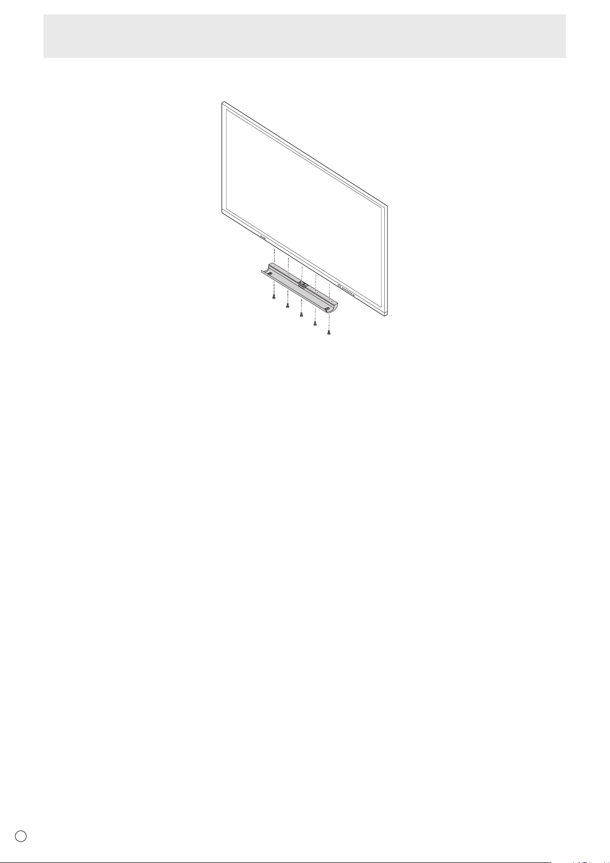
n
Attaching the Tray
Secure the tray using 5 tray mounting screws (M3x15) (supplied).
Mounting Precautions (For SHARP dealers and service engineers)

PN-C861H-C751H HM EN19G(1)