Loading ...
Loading ...
Loading ...
6
EN
www.napoleon.com
N415-0324 OCT 2. 19
Gas Hook-Up Instrucons
WARNING! A re will result if the gas supply hose makes contact with the underside of the grill or
drip pan.
Propane Cylinder Installaon: Set cylinder into hole in boom shelf. Other cylinders may be acceptable
provided they t properly into the tank retaining ring.
Cylinder Connecon: Ensure the gas regulator hose is kink free. Remove the cap or plug from the cylinder
fuel valve. Insert the black QCC1 regulator nipple onto the QCC1 fuel valve. Hand ghten clockwise. Do not
use tools. Leak test all joints prior to using the grill. A leak test must be performed annually and each me
a cylinder is hooked up or if a part of the gas system is replaced.
If this grill is to be connected directly to a house propane gas supply line, follow the instrucons for
the natural gas hook-up. Oponal side burners must also follow the natural gas hook-up instrucons.
Note: The propane tank heat shield is not required when the grill is connected to a xed fuel supply, as its
sole funcon is to shield the propane tank normally used with the grill. Ensure that the supply pressure is
11 inches water column.
Natural Gas Hook-Up: These connecons must be made by a licensed gas er. This natural gas grill is sup-
plied with a gas supply hose (complete with a quick disconnect) designed for natural gas and cered for
outdoor use. The gas grill is designed to operate at an inlet pressure of 7 inches water column. Piping and
valves upstream of the quick disconnect are not supplied. The installaon must comply with CAN B149.1
Natural Gas and Propane installaon code in Canada, or to the Naonal Fuel Gas Code, ANSI Z223.1 in the
United States. The gas supply pipe must be suciently sized to supply the BTU/h specied on the rang
plate, based on the length of the piping run.
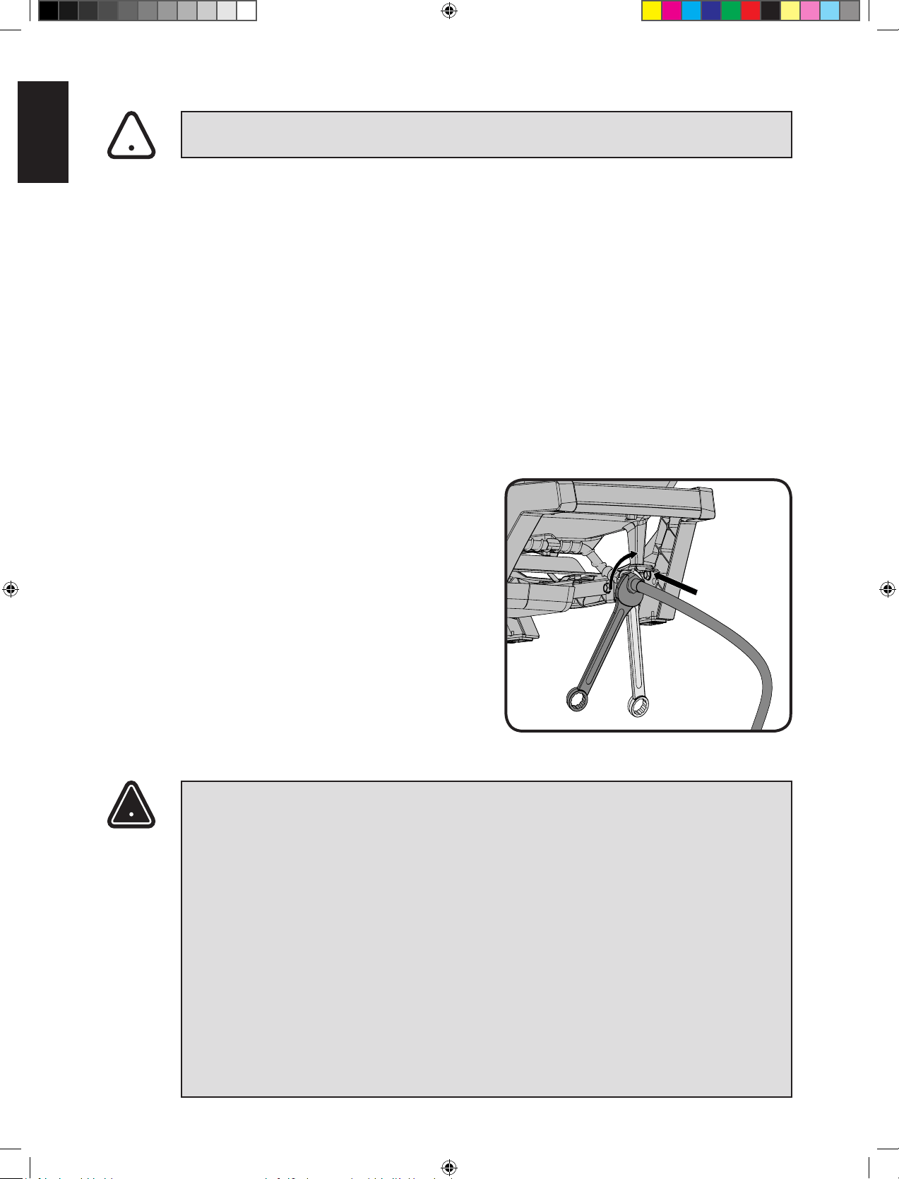
The quick disconnect must not be installed in an
upward direcon and a readily accessible manual
shut-o valve must be installed upstream of, and as
close to, the quick disconnect as is feasible. The ared
end of the hose must be connected to the ng on
the end of the manifold tube or ex tube
(if applicable) as illustrated in the Natural Gas Hose
Aachment diagram. Tighten using two wrenches.
(Do not use thread sealer/pipe dope.) Leak test all
joints prior to using the gas grill.
WARNING!
• The installaon must be performed by a licensed gas er, and all connecons must be leak
tested before operang the grill.
• Do not route hose underneath the drip pan.
• Do not route hose between boom shelf space and back panel.
• Do not route hose over top of rear panel.
• Ensure all hose connecons are ghtened using two wrenches. Do not use Teon
tape or pipe dope on any hose connecon.
• Ensure the hose does not contact any high temperature surfaces or it may melt and leak causing
a re.
• Leak test all the connecons using a soap and water soluon as per the leak tesng instrucons
found in the manual.
• The outdoor cooking gas appliance and its individual shuto valve must be disconnected from
the gas supply piping system during any pressure tesng of that system at test pressures in
excess of 0.5 psi (3.5 kPa).
• The outdoor cooking gas appliance must be isolated from the gas supply piping system by closing
its individual manual shuto valve during any pressure tesng of the gas supply piping system at
test pressures equal to or less than 1/2 psi (3.5 kPa).
!
!
Loading ...
Loading ...
Loading ...