
Loading ...
Loading ...
Loading ...
Eaton Tripp Lite Series SUPDMBP6K User Guide 934705—Rev A 11
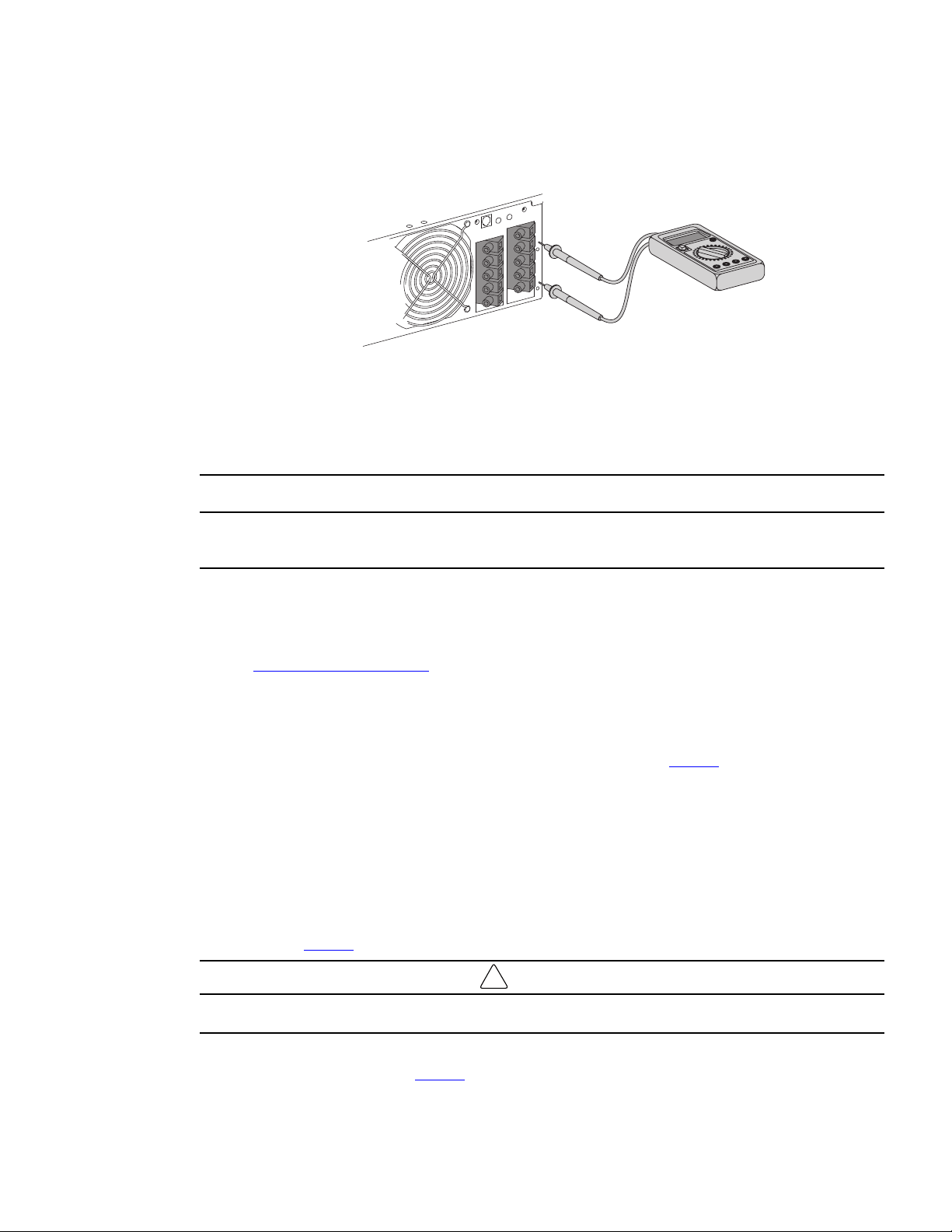
• After opening the UPS I/O terminal blocks cover, verify hazardous voltage is no longer present on UPS
terminal blocks by using an electrical safety tester.
• Disconnect the two power cables, and the bypass module detection cable from the UPS.
• Disconnect all accessories, i.e., EBM, Network communications card (if applicable) that are connected
to the UPS (refer to the Smartonline UPS User's Manual).
• Once all accessories have been disconnected the UPS can be replaced.
Hazardous voltage and lost load risk: do not manipulate the manual bypass switch without the UPS connected
via the I/O cord set.
Return to Normal Operation
Connect the bypass module and the UPS wiring as directed below:
1. Connect the two bypass module power cables to the UPS followed by the bypass module detection cable
see 3.3 Power Cable Connection for more details.
2. Connect the I/O cord set connector to the bypass module, and secure it by fixing the two locking screws.
3. Connect all accessories, i.e., EBM, Network communications card (if applicable), that need to be
connected to the UPS (refer to the Smartonline UPS User's Manual).
4. Set the UPS input switch of the bypass module to the "On" position see Figure 2 .
5. Verify the UPS fans turn on and the display illuminates (refer to the Smartonline UPS User's Manual).
6. Press and hold the UPS power button for 3 seconds to start the UPS (refer to the Smartonline UPS User's
Manual).
7. Put the UPS in internal Bypass mode (refer to the Smartonline UPS User's Manual).
8. Verify that the UPS is in Bypass mode by checking UPS display panel (refer to the Smartonline UPS User's
Manual).
9. Verify that the UPS green LED illuminates, indicating that the UPS output power is available on the bypass
module see Figure 2 .
!
IMPORTANT
Do not continue to the next step if the green UPS LED is Off or the load will be lost.
10. Set the Manual bypass switch to the UPS position: the BYPASS LED will turn Off indicating that the load is
now powered by the UPS see Figure 2 .
UPS Replacement with SUPDMBP6K Bypass Module
Loading ...
Loading ...
Loading ...