
Loading ...
Loading ...
Loading ...
Eaton Tripp Lite Series SUPDMBP6K User Guide 934705—Rev A 7
CChhaapptteerr 33 IInnssttaallllaattiioonn
33..11 MMeecchhaanniiccaall MMoouunnttiinngg
To mount the SUPDMBP6K on the UPS, in the rack or on the wall, see 2.1 Standard Positions .
33..22 IInnssttaallllaattiioonn RReeqquuiirreemmeennttss
NOTE 1 Refer to the Smartonline UPS User's Manual for the circuit breaker current ratings.
NOTE 2 The circuit breaker has to be installed upstream the SUPDMBP6K normal AC source.
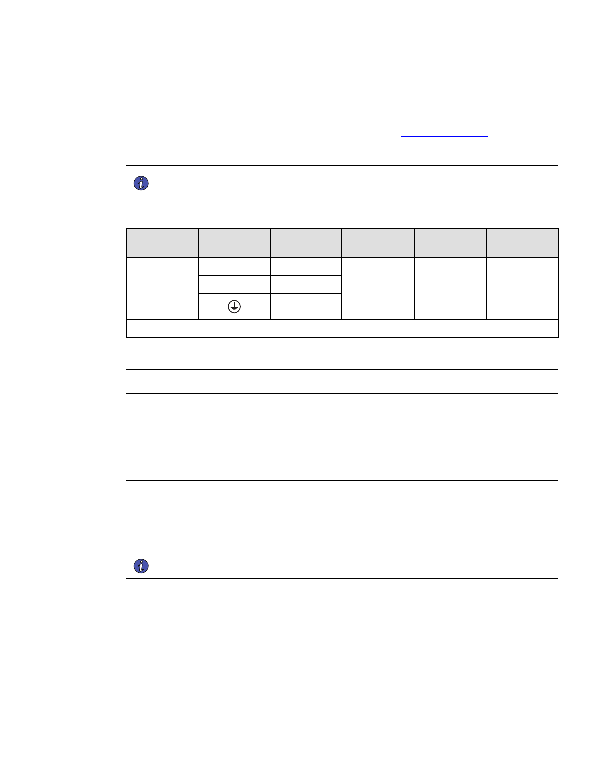
Table 2. Recommended Wire Sizes
Terminal
position
Wire function
Terminal wire
size rating
Minimum input
wire size rating
Tightening
torque
SUPDMBP6K
L1
phase
0.5-10 mm2
(20-8 AWG)
6 mm2 (10 AWG)
105° C
10 mm2 (8 AWG)
75° C
12 lb in
L2 phase
ground
Copper wire, solid or stranded.
33..33 PPoowweerr CCaabbllee CCoonnnneeccttiioonn
This type of connection must be carried out by QUALIFIED ELECTRICAL SERVICE PERSONNEL.
Before carrying out any connection to the SUPDMBP6K, check that the upstream protection device (normal AC
source) is open "O" (Off).
Before proceeding to connect the SUPDMBP6K to the UPS, make sure the UPS has been properly shut down
(refer to the Smartonline UPS User's Manual).
Always connect the ground wire first.
1. Remove the L6-30P input power cable from the UPS I/O terminal blocks, refer to the Smartonline UPS
User's Manual for UPS I/O terminal blocks cover access.
2. Refer to Figure 4 and connect the two power cables of the I/O cord set to the UPS I/O terminal blocks,
following color coding on the cables and the UPS I/O cover (blue for UPS Input / red for UPS Output). Refer
to the Smartonline UPS User's Manual to check the UPS terminal blocks connection.
NOTE Soft soldering of stranded wires is not permitted.
3. Connect the detection cable from the I/O cord set to the UPS (refer to Smartonline UPS User's Manual).
4. Remove the bypass module I/O cover by removing the four screws to access the terminal blocks.
5. Punch out the knockouts and insert the provided cables/conduits inside.
Loading ...
Loading ...
Loading ...