p/n: 934705
Revision A
SUPDMBP6K
Agency Series: AG-0770
Installation and User’s Manual
Eaton Tripp Lite Series SUPDMBP6K

©Copyright 2023 Eaton, Raleigh, NC, USA. All rights reserved. No part of this document may be reproduced in any way without the
express written approval of Eaton.
SSaaffeettyy IInnssttrruuccttiioonnss
SAVE THESE INSTRUCTIONS. This manual contains important instructions that should be
followed during installation and maintenance of the SUPDMBP6K and the UPS.
The SUPDMBP6K models that are covered in this manual are intended for installation in a temperature
controlled environment free of conductive contaminants.
SSppeecciiaall SSyymmbboollss
The following are examples of symbols used on the product to alert you to important information:
RISK OF ELECTRIC SHOCK - Observe the warning associated with the risk of electric shock
symbol.
CAUTION: REFER TO OPERATOR'S MANUAL - Refer to your operator's manual for
additional information, such as important operating and maintenance instructions.
Special Symbols
The following are examples of symbols used on the UPS or accessories to alert you to important
information:
RISK OF ELECTRIC SHOCK - Observe the warning associated with the risk of
electric shock symbol.
CAUTION: REFER TO OPERATOR'S MANUAL - Refer to your operator's manual for
additional information, such as important operating and maintenance
instructions.
This symbol indicates that you should not discard the UPS or the UPS batteries
in the trash. This product contains sealed, lead‐acid batteries and must be
disposed of properly. For more information, contact your local recycling/reuse or
hazardous waste center.
This symbol indicates that you should not discard waste electrical or electronic
equipment (WEEE) in the trash. For proper disposal, contact your local
recycling/reuse or hazardous waste center.
Eaton, Powerware, and BladeUPS are registered trademarks of Eaton Corporation or its subsidiaries and affiliates.
Phillips and Pozidriv are registered trademarks of Phillips Screw Company.
ECopyright 2008–2010 Eaton Corporation, Raleigh, NC, USA. All rights reserved. No part of this document may be
reproduced in any way without the express written approval of Eaton Corporation.
This symbol indicates that you should not discard waste electrical or electronic equipment
(WEEE) in the trash. For proper disposal, contact your local recycling/reuse or hazardous
waste center.

SSaaffeettyy ooff PPeerrssoonnss
• Installation should be performed by QUALIFIED ELECTRICAL SERVICE PERSONNEL ONLY.
• The system has its own power source when connected to the UPS (UPS battery). Consequently,
the power outlets may be energized even if the system is disconnected from the AC power
source. Dangerous voltage levels are present within the system. It should be opened exclusively
by qualified service personnel.
• The system must be properly grounded at all times. Always connect the earth wire first.
PPrroodduucctt SSaaffeettyy
• The connection instructions and operation described in the manual must be followed in the
indicated order. Disconnection and overcurrent protection devices shall be provided by
QUALIFIED ELECTRICAL SERVICE PERSONNEL for AC in/out circuits.
• CAUTION - To reduce the risk of fire, the unit should only connect to a circuit with 20 or 30
amperes maximum branch circuit overcurrent protection in accordance with the National Electric
Code ANSI/NFPA 70 and Canadian Electrical Code, Part 1, C22.1.
• Short Circuit backup protection and overcurrent protection, for the 30A Receptacles, is provided
by the building installation.
• To Avoid Risk of Fire Hazard: When hooking up the power cable connections as described in
3.3 Power Cable Connection, soft soldering of stranded wires is NOT permitted
• The upstream circuit breaker must be easily accessible.
• The unit can be disconnected from AC power source by opening the input circuit breaker, or by
shutting down the UPS (refer to the Smartonline UPS User's Manual).
• Check that the indications on the rating plate correspond to your AC powered system and to the
actual electrical consumption of all the equipment to be connected to the system.
• Never install the system in an excessively damp environment.
• Never let a foreign body penetrate inside the system.
• Never block the cooling vents of the system.
• Never expose the system to direct sunlight or source of heat.
• If the system must be stored prior to installation, storage must be in a dry place.
• The admissible storage temperature range is -15º C to +60º C.
• The operating temperature range is 0 to 40° C
SSppeecciiaall PPrreeccaauuttiioonnss
• The SUPDMBP6K is designed to work with approved Eaton Tripp Lite Series UPS systems
(contact your Eaton Tripp Lite Series reseller for more information)
• All repairs and service should be performed by AUTHORIZED SERVICE PERSONNEL ONLY.
There are NO USER-SERVICEABLE PARTS inside the UPS or Maintenance Bypass Switch.


Eaton Tripp Lite Series SUPDMBP6K User Guide 934705—Rev A v
TTaabbllee ooff CCoonntteennttss
11 IInnttrroodduuccttiioonn....................................................................................................................................................................................................................................................................................................11
1.1 Introduction...............................................................................................................................................1
1.2 Environmental Protection ............................................................................................................................. 1
22 PPrreesseennttaattiioonn ..................................................................................................................................................................................................................................................................................................33
2.1 Standard Positions ......................................................................................................................................3
2.2 Dimensions ...............................................................................................................................................3
2.3 Description / Panels ....................................................................................................................................4
2.4 Inspecting the Equipment.............................................................................................................................5
2.5 Unpacking the SUPDMBP6K.........................................................................................................................5
2.6 Checking the Accessory Kit ..........................................................................................................................5
33 IInnssttaallllaattiioonn ......................................................................................................................................................................................................................................................................................................77
3.1 Mechanical Mounting .................................................................................................................................. 7
3.2 Installation Requirements............................................................................................................................. 7
3.3 Power Cable Connection .............................................................................................................................. 7
44 OOppeerraattiioonnss........................................................................................................................................................................................................................................................................................................99
4.1 UPS Start-UP with SUPDMBP6K Bypass Module ..............................................................................................9
4.2 UPS Replacement with SUPDMBP6K Bypass Module...................................................................................... 10
4.3 UPS Maintenance with SUPDMBP6K Bypass Module ...................................................................................... 12
55 SSuuppppoorrtt ............................................................................................................................................................................................................................................................................................................ 1133
5.1 Service and Support .................................................................................................................................. 13
66 SSppeecciiffiiccaattiioonnss.......................................................................................................................................................................................................................................................................................... 1155
6.1 Model Specifications ................................................................................................................................. 15


Eaton Tripp Lite Series SUPDMBP6K User Guide 934705—Rev A 1
CChhaapptteerr 11 IInnttrroodduuccttiioonn
11..11 IInnttrroodduuccttiioonn
Thank you for selecting an EatonTripp Lite Series product to protect your electrical equipment.
The SUPDMBP6K maintenance bypass has been designed with the utmost care.
We recommend that you take the time to read this manual to take full advantage of the many features of your
SUPDMBP6K bypass module.
Before installing the SUPDMBP6K with your UPS, please read the safety instructions. Then follow instructions
in this manual.
To discover the entire range of Eaton Tripp Lite Series products, we invite you to visit our web site at
TrippLite.eaton.com or contact your EatonTripp Lite representative.
11..22 EEnnvviirroonnmmeennttaall PPrrootteeccttiioonn
Eaton products have implemented an environmental-protection policy.
Products are developed according to an eco-design approach.
Substances
This product does not contain CFCs, HCFCs, or asbestos.
Packing
To improve waste treatment and facilitate recycling, separate the various packing components.
• The cardboard we use comprises over 50% of recycled cardboard.
• All bags are made of polyethylene.
• Packing materials are recyclable and bear the appropriate identification symbol
01
PET
Table 1. Packing Material Symbols
Materials Abbreviations Number in the symbols
Polyethylene terephthalate PET
01
High-density polyethylene HDPE 02
Polyvinyl chloride PVC
03
Low-density polyethylene LDPE 04
Polypropylene PP 05
Polystyrene PS
06
Follow all local regulations for the disposal of packing materials.
End of Life
Eaton will process products at the end of their service life in compliance with local regulations. Eaton works
with companies in charge of collecting and eliminating our products at the end of their service life.

2 Eaton Tripp Lite Series SUPDMBP6K User Guide 934705—Rev A
Product
The product is made up of recyclable materials.
Dismantling of the bypass module must done in compliance with all local regulations concerning waste. At the
end of its service life, the product must be transported to a processing center for electronic waste.
Benefits
The SUPDMBP6K bypass module makes it possible to service or even replace the UPS without affecting the
connected loads (HotSwap function).
Providing outstanding reliability, the Tripp Lite Series SUPDMBP6K bypass module unique benefits include:
• Easy and fast connection to UPS due to Input/Output and signal “all in one” patented connector.
• “Make before Break” feature to allow full servicing (electrical power continuity) when switching from the
UPS position to the Bypass position (and vice versa).
• Communication feature with UPS*: detection of the UPS connection and switch position (Normal or
Bypass).
• Load connection by hardwired terminal blocks and locking receptacle cords two NEMA 20 A L6–20R and
two NEMA (30 A L6-30R) cordsets.
• Adjustable 19’’ rack kit and multiple positions tower installation kit provided.
• Backed by worldwide agency certifications.
Environmental Protection
Eaton Tripp Lite Series SUPDMBP6K User Guide 934705—Rev A 3
CChhaapptteerr 22 PPrreesseennttaattiioonn
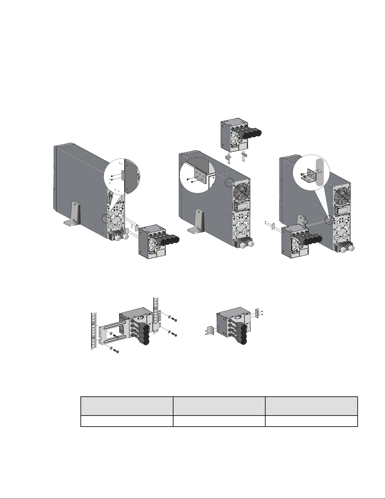
22..11 SSttaannddaarrdd PPoossiittiioonnss
Figure 1. SUPDMBP6K Installation Options
Tower installation
Rack installation
Wall mounting
22..22 DDiimmeennssiioonnss
Description Weight
(lb/ kg)
Dimensions (inch/mm)
D x W x H
SUPDMBP6K
5.5 / 2.5 4.3 x 7.0 x 5.1 / 110 x 177 x 130
4 Eaton Tripp Lite Series SUPDMBP6K User Guide 934705—Rev A
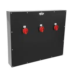
22..33 DDeessccrriippttiioonn // PPaanneellss
The SUPDMBP6K has a manual rotary bypass switch with two positions:
• UPS: the load is supplied by the UPS.
• Bypass: the load is supplied directly by the AC source.
Two lights that indicate the SUPDMBP6K power status:
• “UPS” green LED: when active, the UPS output is available, the bypass switch can be safely turned to the
UPS position.
• “BYPASS” red LED: when active, indicates that the SUPDMBP6K is on "Bypass mode" (The bypass
switch is turned to the bypass position).
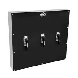
UPS input switch
Switches off the AC source to the UPS for maintenance or replacement.
SUPDMBP6K status detection:
A signal cable, with RJ11 connector to plug to the UPS, allows the communication to the UPS to manage the
SUPDMBP6K status, and the indication on UPS display panel of both following status:
• SUPDMBP6K connection to UPS.
• Manual bypass switch position.
Check the Smartonline UPS User's Manual to check the compatibility of this feature, or contact Tripp Lite for
more information.
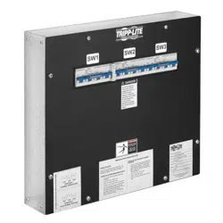
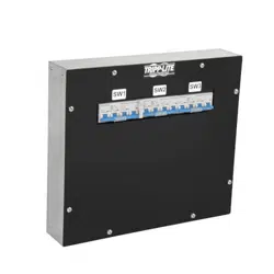
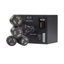
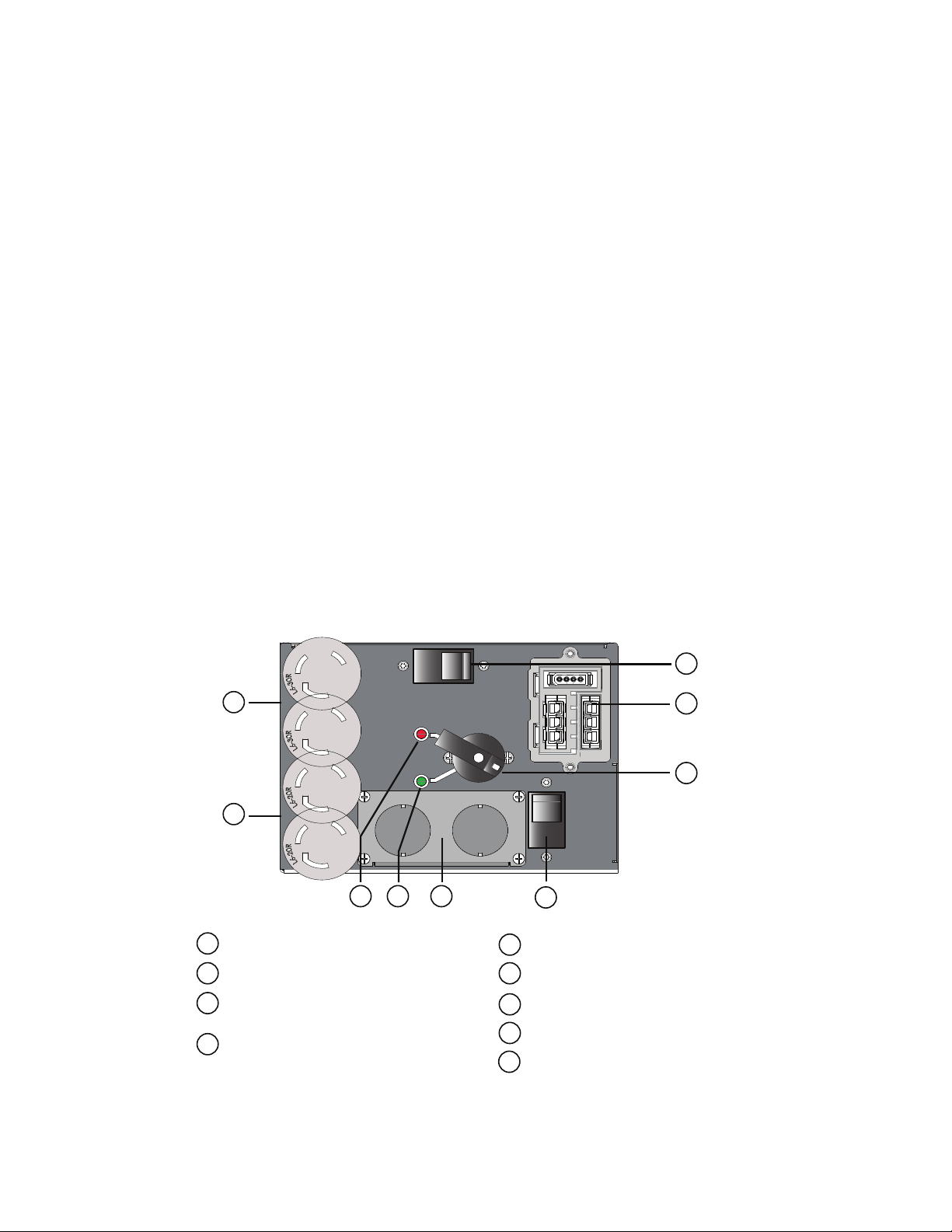
Figure 2. SUPDMBP6K
Input / Output terminal blocks
UPS input switch
Input / Output detection connector to
UPS
Manual bypass switch
(2) L6-30 locking receptacle cords
(2) L6-20 locking receptacle cords
“Bypass” mode red LED
UPS mode green LED
1
2
3
5
6
7
8
4
1
2
3
4
5
6
7
8
9
9
20A double pole 250V breaker
ON
ON
OFF
OFF
BYPASS
UPS
UPS INPUT SWITCH
NORMAL AC SOURCE
OUTPUT
20 AMP
Description / Panels
Eaton Tripp Lite Series SUPDMBP6K User Guide 934705—Rev A 5
22..44 IInnssppeeccttiinngg tthhee EEqquuiippmmeenntt
If any equipment has been damaged during shipment, keep the shipping cartons and packing materials for the
carrier or place of purchase and file a claim for shipping damage. If you discover damage after acceptance, file a
claim for the concealed damage.
To file a claim for shipping damage or concealed damage:
1. File with the carrier within 15 days of receipt of the equipment.
2. Send your service representative a copy of the damage claim within 15 days. See 5.1 Service and Support.
22..55 UUnnppaacckkiinngg tthhee SSUUPPDDMMBBPP66KK
Unpack the equipment and remove all of the packing materials and shipping cartons.
Discard or recycle the packaging responsibly, or store it for future use. Place the SUPDMBP6K in a protected
area with adequate airflow free of humidity, flammable gas, and corrosion.
NOTE Packing materials must be disposed of in compliance with all local regulations
concerning waste. Recycling symbols are printed on the packing materials to facilitate
sorting.
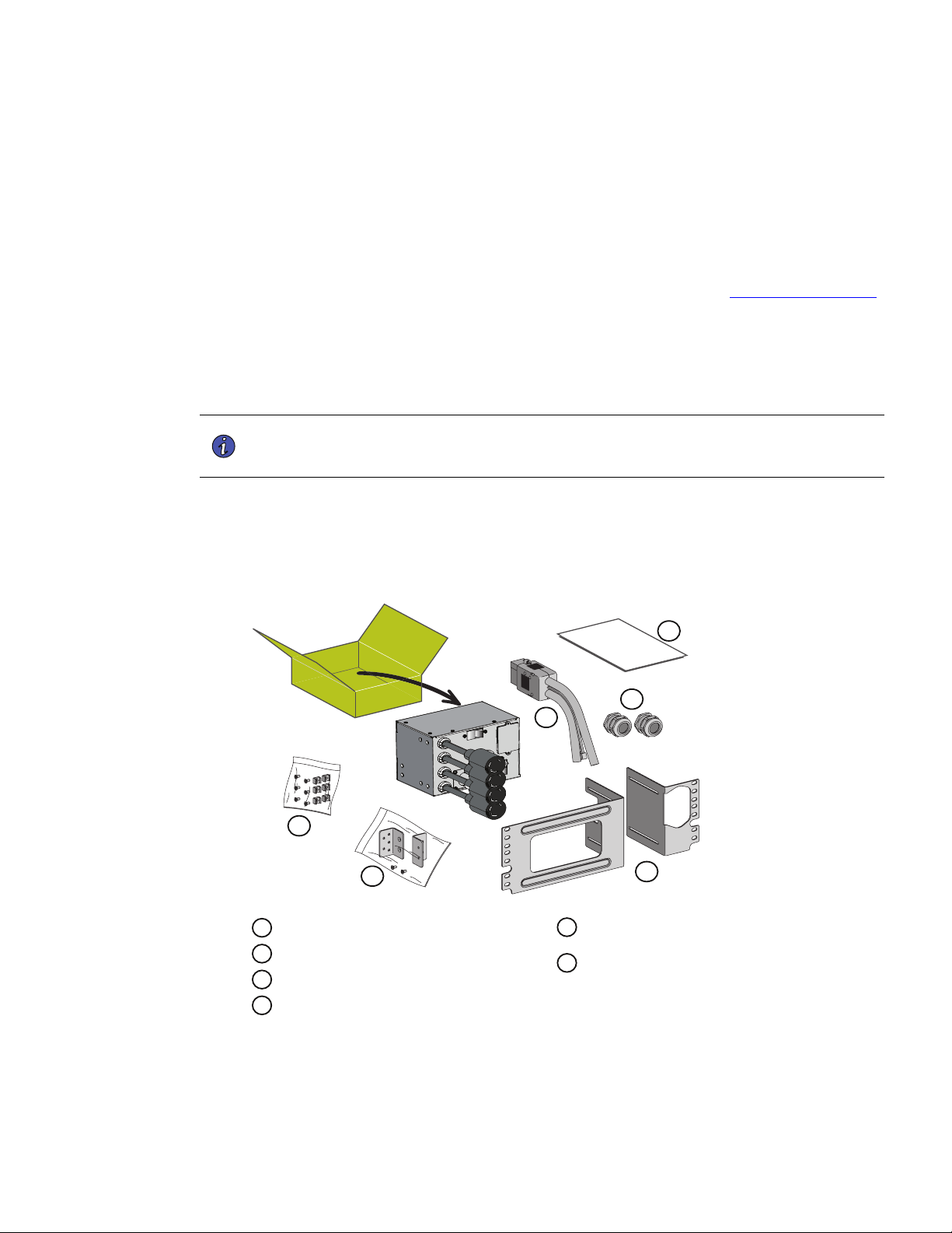
22..66 CChheecckkiinngg tthhee AAcccceessssoorryy KKiitt
Verify that the following additional items are included with the SUPDMBP6K:
Figure 3. SUPDMBP6K
Input / Output UPS cord set
(2) cable glands
Rack kit for 19 inch enclosures
Fixation kit for rack mounting
(including square nuts and screws)
1
2
3
4
Tower and wall mounting kit
(inclusing 2 ears and screws)
Installation and user manual
5
6
1
2
3
4
5
6
Inspecting the Equipment

Eaton Tripp Lite Series SUPDMBP6K User Guide 934705—Rev A 7
CChhaapptteerr 33 IInnssttaallllaattiioonn
33..11 MMeecchhaanniiccaall MMoouunnttiinngg
To mount the SUPDMBP6K on the UPS, in the rack or on the wall, see 2.1 Standard Positions .
33..22 IInnssttaallllaattiioonn RReeqquuiirreemmeennttss
NOTE 1 Refer to the Smartonline UPS User's Manual for the circuit breaker current ratings.
NOTE 2 The circuit breaker has to be installed upstream the SUPDMBP6K normal AC source.
Table 2. Recommended Wire Sizes
Terminal
position
Wire function
Terminal wire
size rating
Minimum input
wire size rating
Tightening
torque
SUPDMBP6K
L1
phase
0.5-10 mm2
(20-8 AWG)
6 mm2 (10 AWG)
105° C
10 mm2 (8 AWG)
75° C
12 lb in
L2 phase
ground
Copper wire, solid or stranded.
33..33 PPoowweerr CCaabbllee CCoonnnneeccttiioonn
This type of connection must be carried out by QUALIFIED ELECTRICAL SERVICE PERSONNEL.
Before carrying out any connection to the SUPDMBP6K, check that the upstream protection device (normal AC
source) is open "O" (Off).
Before proceeding to connect the SUPDMBP6K to the UPS, make sure the UPS has been properly shut down
(refer to the Smartonline UPS User's Manual).
Always connect the ground wire first.
1. Remove the L6-30P input power cable from the UPS I/O terminal blocks, refer to the Smartonline UPS
User's Manual for UPS I/O terminal blocks cover access.
2. Refer to Figure 4 and connect the two power cables of the I/O cord set to the UPS I/O terminal blocks,
following color coding on the cables and the UPS I/O cover (blue for UPS Input / red for UPS Output). Refer
to the Smartonline UPS User's Manual to check the UPS terminal blocks connection.
NOTE Soft soldering of stranded wires is not permitted.
3. Connect the detection cable from the I/O cord set to the UPS (refer to Smartonline UPS User's Manual).
4. Remove the bypass module I/O cover by removing the four screws to access the terminal blocks.
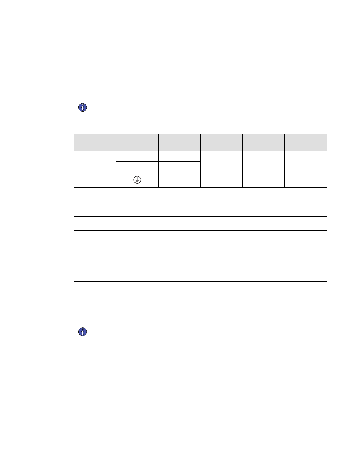
5. Punch out the knockouts and insert the provided cables/conduits inside.
8 Eaton Tripp Lite Series SUPDMBP6K User Guide 934705—Rev A
1
1
6. Insert the L6-30P input power cable through the cable gland.
7. Connect the wires to the Normal AC source (Input) terminal blocks.
8. Insert the output cable through the cable gland.
9. Connect the wires to the output terminal blocks.
10. Tighten the cable glands.
11. Slide back and secure the SUPDMBP6K I/O cover with the four screws.
12. Connect the I/O cord set connector to the SUPDMBP6K, and secure it by tightening the two locking
screws.
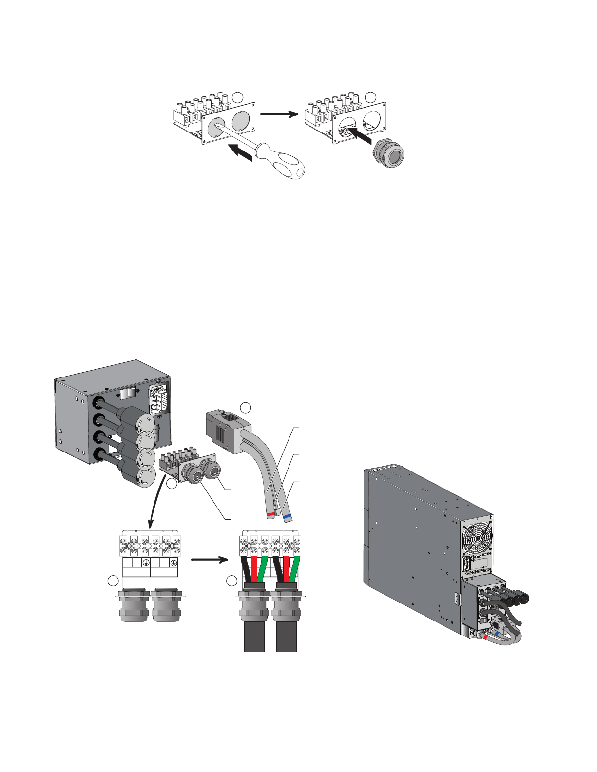
Figure 4. Power Cable Connections
1
2
OUTPUT
L1 L2
INPUT
L1 L2
2
OUTPUT
L1 L2 t
INPUT
L1 L2 t
2
Normal AC source
cable
Output cable
To UPS normal
AC source
To UPS output
RJ11 UPS detection
Utility
power
Load
Power Cable Connection
Eaton Tripp Lite Series SUPDMBP6K User Guide 934705—Rev A 9
CChhaapptteerr 44 OOppeerraattiioonnss
44..11 UUPPSS SSttaarrtt--UUPP wwiitthh SSUUPPDDMMBBPP66KK BByyppaassss MMoodduullee
Verify that the load equipment ratings do not exceed the UPS capacity to prevent an overload alarm.
1. Check that the UPS is correctly connected to the bypass module (see 3.3 Power Cable Connection).
NOTE Do not connect any load equipment to the UPS outlets. Loads can only be connected to
the SUPDMBP6K outlets or hardwired output terminal blocks.
2. Verify that the bypass module terminal block wiring is connected to the AC input and output source.
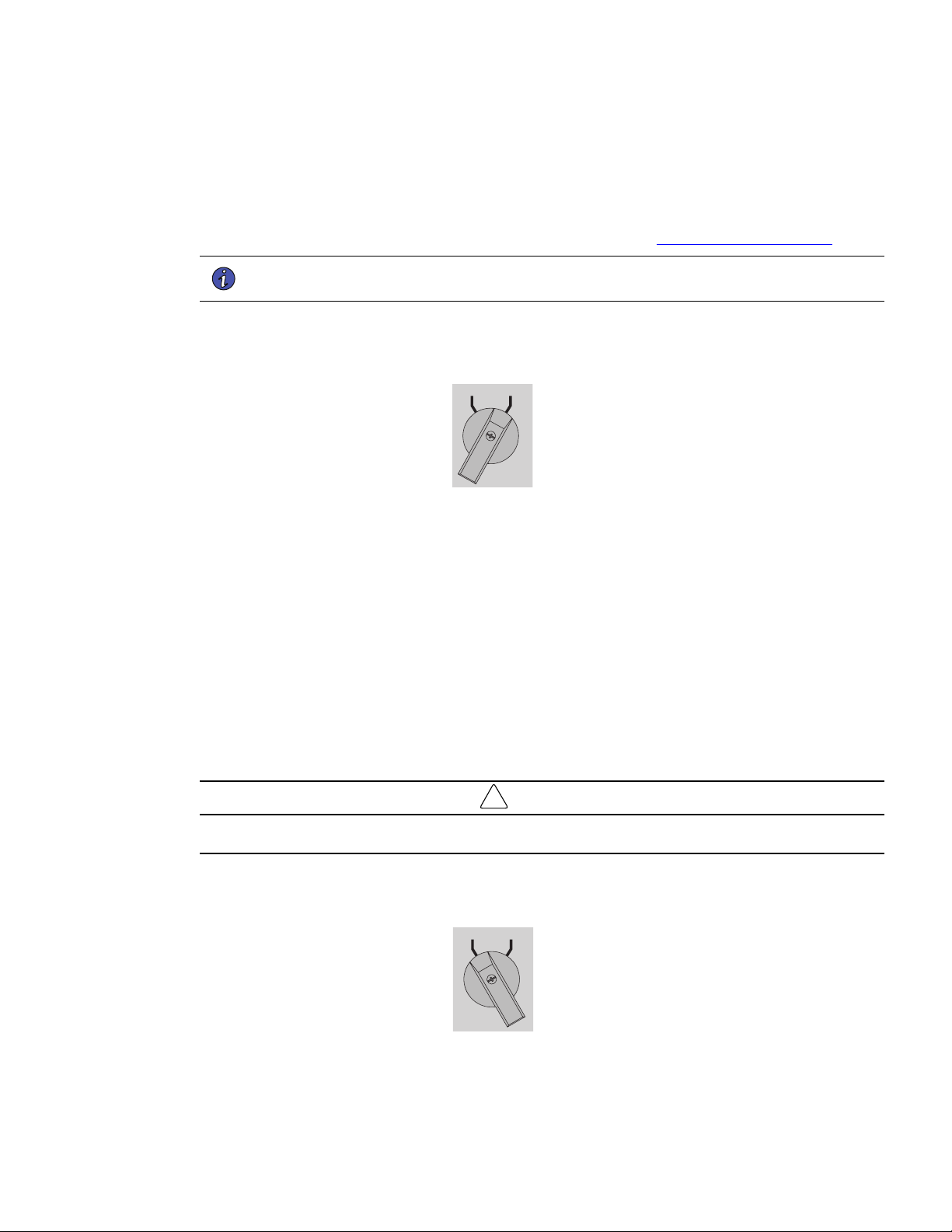
3. Check that the Manual bypass switch is set to the BYPASS position.
UPS BYPASS
4. Set the upstream circuit breaker (not provided) to the "I" position (On) to switch On the utility power.
5. Verify that the red BYPASS LED illuminates, indicating that the AC source now powers the load.
6. Set the UPS input switch of the bypass module to the On position.
7. Verify that the UPS is correctly powered and the UPS display panel illuminates (refer to the Smartonline
UPS User's Manual).
8. Press and hold the UPS On button for three seconds to start the UPS.
9. Put the UPS in internal Bypass mode (refer to the Smartonline UPS User's Manual).
10. Verify that the UPS is on Bypass mode by checking UPS display panel (refer to the Smartonline UPS User's
Manual).
11. Verify that the green UPS LED on the bypass module illuminates, indicating that UPS output power is
available on the bypass module.
!
IMPORTANT
Do not continue to the next step if the green UPS LED on the bypass module is Off or the load will be lost.
12. Set the Manual bypass switch to the UPS position: the BYPASS LED will turn Off indicating that the load is
now powered by the UPS.
UPS BYPASS
13. Put the UPS in Normal mode (refer to the Smartonline UPS User's Manual).
10 Eaton Tripp Lite Series SUPDMBP6K User Guide 934705—Rev A
14. Check that the UPS is in Online mode by checking UPS display panel (refer to the Smartonline UPS User's
Manual) the load is now protected by the UPS.
44..22 UUPPSS RReeppllaacceemmeenntt wwiitthh SSUUPPDDMMBBPP66KK BByyppaassss MMoodduullee
To disconnect the UPS from the bypass module follow the steps in this section.
1. Put the UPS in internal Bypass mode (refer to the Smartonline UPS User's Manual).
2. Verify that the UPS is on Bypass mode by checking UPS display panel (refer to the Smartonline UPS User's
Manual).
3. Set the Manual bypass switch to “BYPASS” position. The red “BYPASS” LED will turn On indicating that
the load is supplied directly by AC source.
UPS BYPASS
4. Switch the UPS input switch to the Off position and wait 30 seconds.
5. Wait for the UPS fans to stop and the display to turn off, the UPS can now be disconnected, as described
below:
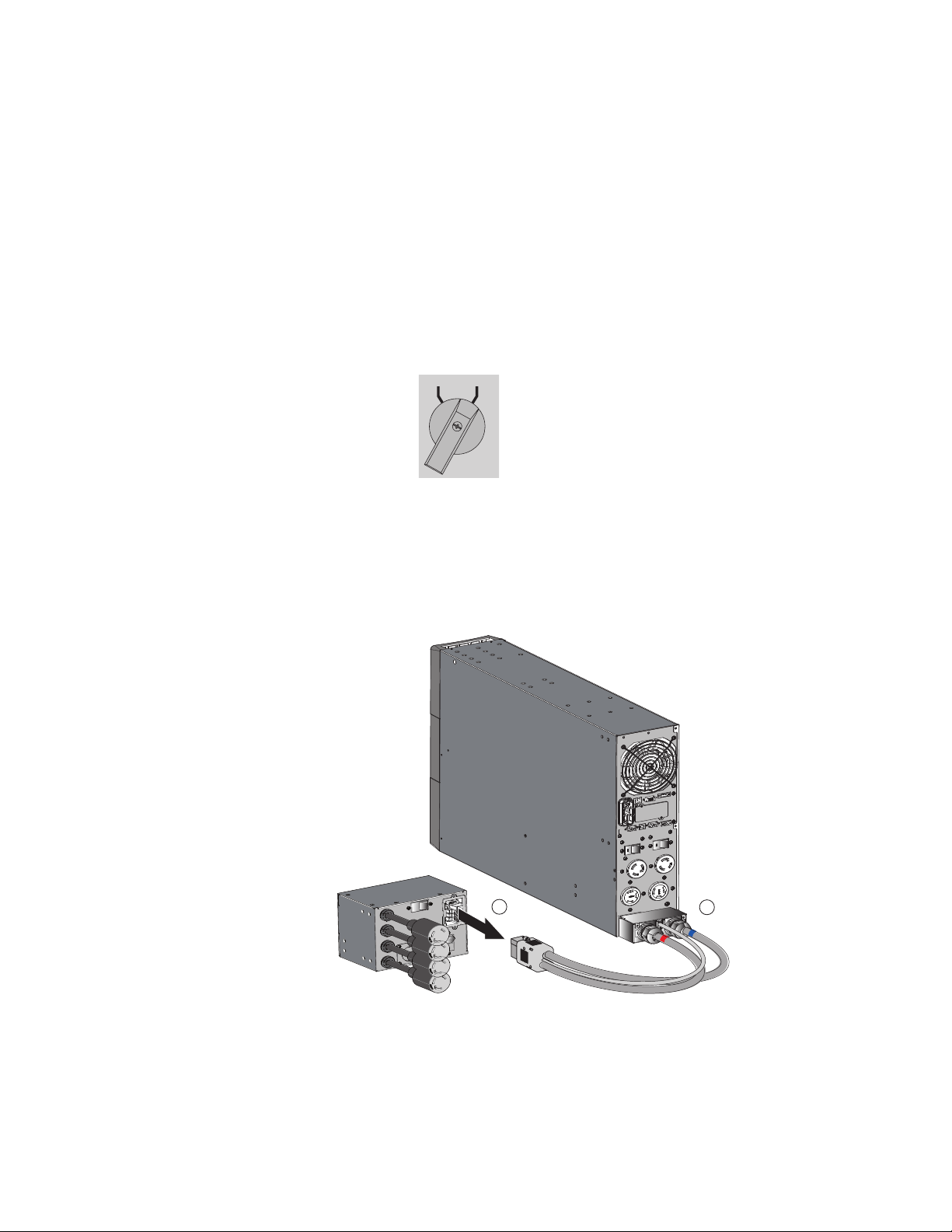
• Loosen the two screws that hold the I/O cord set in place on the bypass module, and then disconnect
the cable.
1
2
• Remove the screws that hold the UPS I/O terminal block access cover in place.
UPS Replacement with SUPDMBP6K Bypass Module
Eaton Tripp Lite Series SUPDMBP6K User Guide 934705—Rev A 11
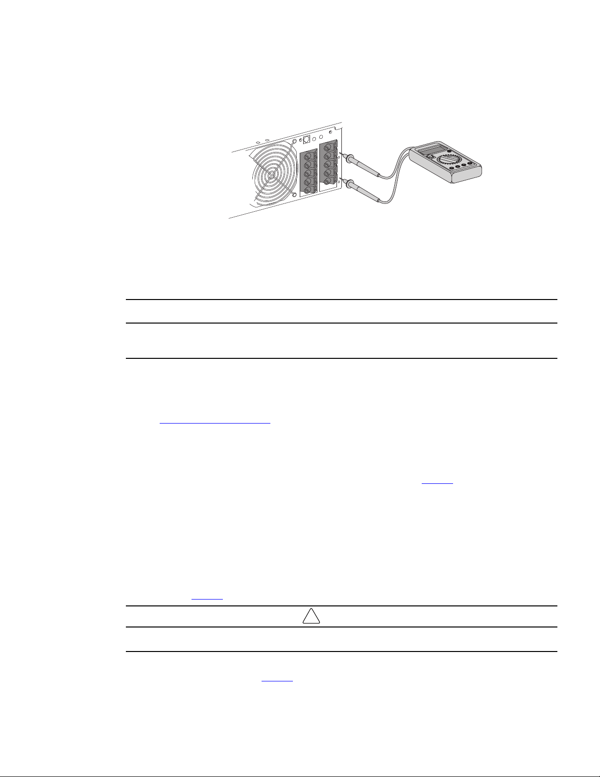
• After opening the UPS I/O terminal blocks cover, verify hazardous voltage is no longer present on UPS
terminal blocks by using an electrical safety tester.
• Disconnect the two power cables, and the bypass module detection cable from the UPS.
• Disconnect all accessories, i.e., EBM, Network communications card (if applicable) that are connected
to the UPS (refer to the Smartonline UPS User's Manual).
• Once all accessories have been disconnected the UPS can be replaced.
Hazardous voltage and lost load risk: do not manipulate the manual bypass switch without the UPS connected
via the I/O cord set.
Return to Normal Operation
Connect the bypass module and the UPS wiring as directed below:
1. Connect the two bypass module power cables to the UPS followed by the bypass module detection cable
see 3.3 Power Cable Connection for more details.
2. Connect the I/O cord set connector to the bypass module, and secure it by fixing the two locking screws.
3. Connect all accessories, i.e., EBM, Network communications card (if applicable), that need to be
connected to the UPS (refer to the Smartonline UPS User's Manual).
4. Set the UPS input switch of the bypass module to the "On" position see Figure 2 .
5. Verify the UPS fans turn on and the display illuminates (refer to the Smartonline UPS User's Manual).
6. Press and hold the UPS power button for 3 seconds to start the UPS (refer to the Smartonline UPS User's
Manual).
7. Put the UPS in internal Bypass mode (refer to the Smartonline UPS User's Manual).
8. Verify that the UPS is in Bypass mode by checking UPS display panel (refer to the Smartonline UPS User's
Manual).
9. Verify that the UPS green LED illuminates, indicating that the UPS output power is available on the bypass
module see Figure 2 .
!
IMPORTANT
Do not continue to the next step if the green UPS LED is Off or the load will be lost.
10. Set the Manual bypass switch to the UPS position: the BYPASS LED will turn Off indicating that the load is
now powered by the UPS see Figure 2 .
UPS Replacement with SUPDMBP6K Bypass Module
12 Eaton Tripp Lite Series SUPDMBP6K User Guide 934705—Rev A
11. Put the UPS in Normal mode (refer to the Smartonline UPS User's Manual).
12. Check that the UPS is in Online mode by checking UPS display panel (refer to the Smartonline UPS User's
Manual).
44..33 UUPPSS MMaaiinntteennaannccee wwiitthh SSUUPPDDMMBBPP66KK BByyppaassss MMoodduullee
To go to maintenance Bypass operation (follow the MANDATORY steps below):
1. Put the UPS in internal Bypass mode (refer to the Smartonline UPS User's Manual),
2. Verify that the UPS is on Bypass mode by checking UPS display panel (refer to the Smartonline UPS User's
Manual).
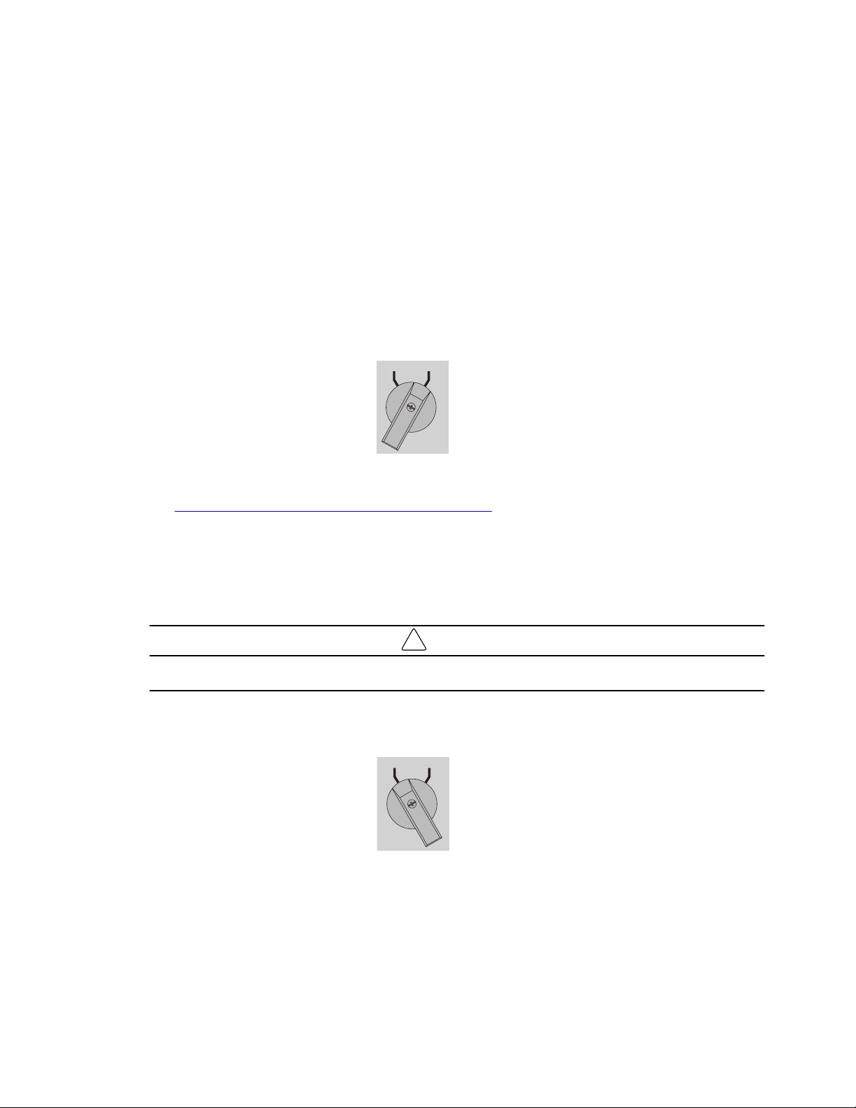
3. Set the Manual bypass switch to BYPASS position. The red BYPASS LED will illuminate indicating that the
load is powered directly by the utility source.
UPS BYPASS
4. The UPS can now be safety serviced. If the UPS needs to be replaced see
4.2 UPS Replacement with SUPDMBP6K Bypass Module.
Return to Normal Operation.
1. Verify that the UPS is on Bypass mode by checking UPS display panel (refer to the Smartonline UPS User's
Manual).
2. Verify that the green UPS LED light is illuminated, indicating that the UPS output power is available on the
bypass module.
!
IMPORTANT
Do not continue to next the step if the green UPS mode LED is Off or the load will be lost.
3. Set the Manual bypass switch to the UPS position: the BYPASS LED turns Off indicating that the load is
now powered by the UPS.
UPS BYPASS
4. Put the UPS in Normal mode (refer to the Smartonline UPS User's Manual).
5. Check that the UPS is in Online mode by checking UPS display panel ensuring the load is protected by the
UPS (refer to the Smartonline UPS User's Manual).
UPS Maintenance with SUPDMBP6K Bypass Module

Eaton Tripp Lite Series SUPDMBP6K User Guide 934705—Rev A 13
CChhaapptteerr 55 SSuuppppoorrtt
55..11 SSeerrvviiccee aanndd SSuuppppoorrtt
If you have any questions or problems with the UPS, call your Local Distributor or Eaton Support at one of
the following telephone numbers and ask for a UPS technical representative.
United States:
1–800–356–5737
Canada:
1–800–461–9166 ext 260
All other countries: Call your local service representative
Please have the following information ready when you call Eaton Support:
• Model number
• Serial number
• Version number (if available)
• Date of failure or problem
• Symptoms of failure or problem
• Customer return address and contact information
If repair is required, you will be given a Returned Material Authorization (RMA) number. This number must
appear on the outside of the package and on the Bill Of Lading (if applicable). Use the original packaging or
request packaging from Eaton Support or your local distributor. Units damaged in shipment as a result of
improper packaging are not covered under warranty. A replacement or repair unit will be shipped, and freight
prepaid for all units within the warranty period.
NOTE For critical applications, immediate replacement may be available. Call Eaton Support
for the dealer or distributor nearest you.

Eaton Tripp Lite Series SUPDMBP6K User Guide 934705—Rev A 15
CChhaapptteerr 66 SSppeecciiffiiccaattiioonnss
66..11 MMooddeell SSppeecciiffiiccaattiioonnss
Table 3. Input Connection
SUPDMBP6K input connection
SUPDMBP6K Terminal blocks
Table 4. Output Connection
SUPDMBP6K output connections
Two L6-30 cords + terminal blocks Two L6-20 cords + terminal blocks
Table 5. Dimensions
SUPDMBP6K overall dimensions
D x W x H (inch / mm)
5.6 x 7.0 x 5.1 /
142 x 177 x 130
Table 6. Weight
SUPDMBP6K weight
Weight lb / (kg)
5.5 / 2.5
Table 7. Performance
SUPDMBP6K performance
Nominal voltage 200 - 240 V
Frequency 50/60 Hz
Input nominal Current 25A
Maximal power 6000VA
Table 8. Standards
SUPDMBP6K standards
Safety standards (Canada) CAN/CSA-C22.2 No. 107.3-14 (3rd Ed)+GI1 (R:2017-10)
Safety standards (U.S.) UL1778:2014 (5th Ed) R10.17
Table 9. Environmental
SUPDMBP6K environmental performance
Operating temperature 0 to 40° C (32 to 104° F)
Storage temperature -15 to 60° C (5 to 140° F)
Transit temperature
-25 to 55° C (-13 to 130° F)
16 Eaton Tripp Lite Series SUPDMBP6K User Guide 934705—Rev A
Table 9. Environmental (Continued)
SUPDMBP6K environmental performance
Humidity 0 to 95% no condensing
Operation altitude Up to 3,000 meters (9,843 ft) above sea level with 10% derating
per 1000 meters
Transit altitude
Up to 10,000 meters (32,808 ft) above sea level
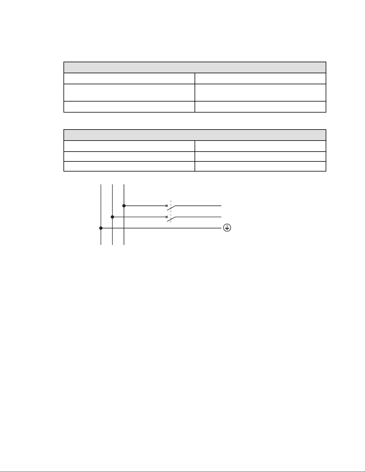
Table 10. Recommended Upstream Protection
SUPDMBP6K over current protection
UPS power rating Upstream circuit breaker
5000VA D curve - 30A
6000VA D curve - 30A
2 poles circuit breaker
G N(L2) L1
N(L2)
L1
to UPS Normal AC source
Model Specifications


934705A
934705 A