
ArtiDiag Pro
英文说明书(英文)印刷要求
说明
1、材质及幅面尺寸:内页 80g 书写纸 ;封面 / 封底 157g
双铜纸;副面尺寸:128(宽)*182(高)mm;封面 / 封
底幅面尺寸与正文幅面尺寸相同;
2、颜色:封底彩色,内页黑白
3、装订方式:骑马钉

ArtiDiag Pro
Professional Diagnostic Tool
USER MANUAL


Welcome ......................................................................................................... 1
About ................................................................................................................. 1
What's Included ......................................................................................... 1
Technical Specication ........................................................................ 2
Compatibility ...............................................................................................2
Notice ............................................................................................................... 2
General Information of OBDII .........................................................3
Diagnostic Trouble Codes (DTCs) ..................................................3
Product Overview ....................................................................................4
Preparation & Connection..................................................................6
Operation Introduction ......................................................................10
Warnings ..................................................................................................... 32
Cautions ....................................................................................................... 32
FAQ ................................................................................................................. 33
Warranty ......................................................................................................34
CONTENTS


EN
1
WELCOME
ABOUT
WHAT'S INCLUDED
Thank you for purchasing the TOPDON ArtiDiag Pro, an automotive
diagnostic tool. Please read manual prior to operation.
The TOPDON ArtiDiag Pro is an ideal diagnostic tablet designed to
work on all available electronic systems. Beyond OBD2 diagnostics,
the user can expect AutoVIN technology to accelerate diagnostic
work, and the well-organized interface can run reset services for
effective vehicle maintenance.
1. ArtiDiag Pro
2. Diagnostic Cable
3. Smart OBD II-16E Adaptor
4. BENZ-38 Adaptor
5. BMW-20 Adaptor
6. 5V DC Charging Cable
7. Power Adaptors
8. Carrying Case
9. Quick User Guide
10. User Manual

2
ArtiDiag Pro may automatically reset while being disturbed by strong
static electricity. THIS IS A NORMAL REACTION.
This Product Manual is subject to change without written notice.
Read the instructions carefully and use the unit properly. Failure to
do so may cause damage and/or personal injury, which will void the
product warranty.
NOTICE
Display: 7-inch 1024*600 Touchable Screen
RAM: 2G
ROM: 32GB
OBDII Input Voltage Range: 9~18V
Charging: 5V DC, or through connection to vehicle’s DLC
Working Temperature: 14°F to 122°F (-10°C to 50°C)
Storage Temperature: -4°F to 158°F (-20°C to 70°C)
TECHNICAL SPECIFICATION
COMPATIBILITY
TOPDON ArtiDiag Pro is compatible with the following:
•
KWP2000
•
ISO9141
•
J1850 VPW
•
J1850 PWM
•
CAN (Controller Area Network)
•
And more
EN
3
The OBDII system is designed to monitor emission control systems
and key engine components by performing either continuous or
periodic tests of specic components and vehicle conditions, which
will relay the following information:
•
Whether the Malfunction Indicator Light (MIL) is commanded “on”
or “off”;
•
Which, if any, Diagnostic Trouble Codes (DTCs) are stored;
•
Readiness Monitor status.
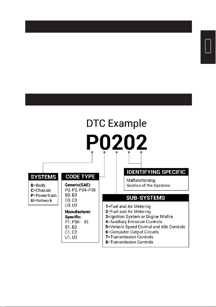
DIAGNOSTIC TROUBLE CODES (DTCS)
GENERAL INFORMATION OF OBDII
P
4
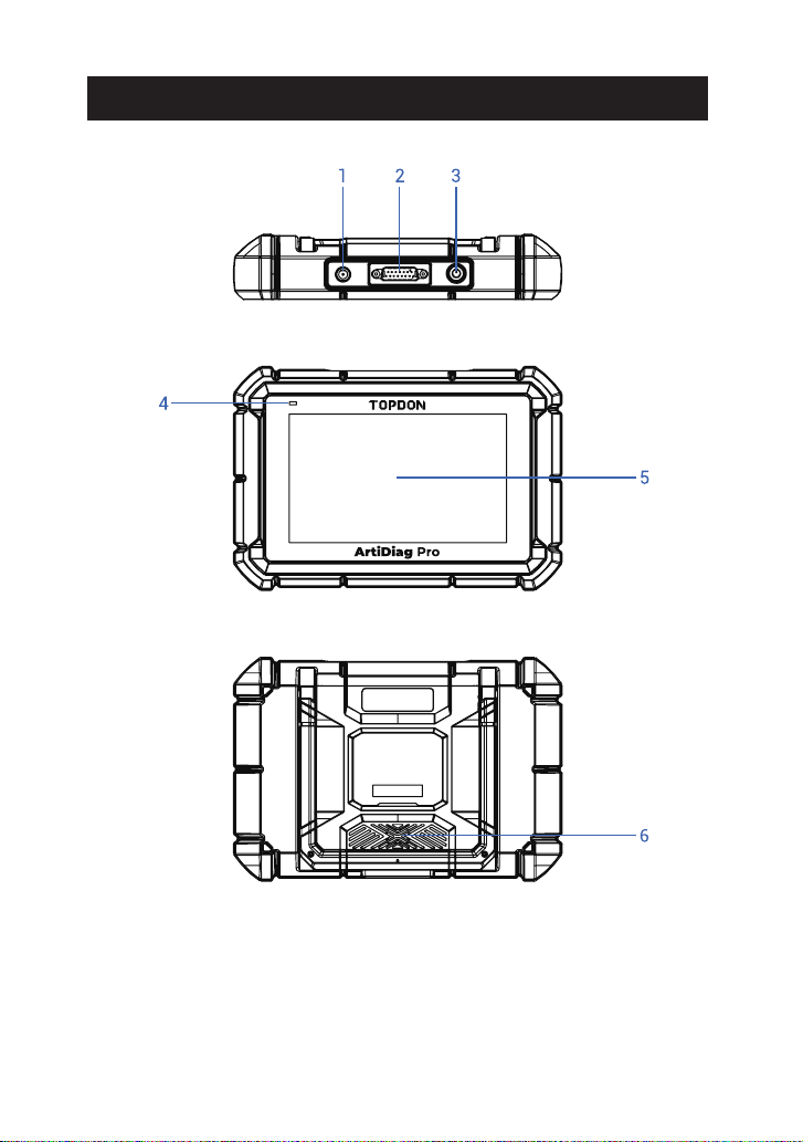
PRODUCT OVERVIEW

EN
5
To charge the tablet.
Convert an audio signal into a corresponding
sound.
Show test results.
•
Hold the button for 5 seconds to turn the tablet
on.
•
Hold the button for 3 seconds to turn the tablet
off.
•
Press the button to wake up the screen or turn
off the screen.
Battery below 20% indicates low battery. Battery
above 20% indicates normal battery.
•
For low battery, it illuminates red and ashes
when being charged. If not charged, it
illuminates solid red.
•
For normal battery, it illuminates green and
ashes when being charged.
Power/Lock
Button
Charging LED
5V DC Charging
Port
Loudspeakers
Touch Screen
NameNO.
Descriptions
To connect to the diagnostic cable.
1
2
3
4
5
6
DB-15 Diagnostic
Connector
6
1. Turn the ignition off.
2. Locate the vehicle’s DLC socket.
3. Connect one end of the diagnostic cable to the DB-15 port on the
ArtiDiag Pro and tighten the captive screws.
4. Select the appropriate adaptor for vehicle's DLC connector. Connect
the adaptor to the other end of the diagnostic cable and tighten
the captive screws.
5. Plug the adaptor to vehicle's DLC connector.
6. Turn the ignition on. The engine can be off or running.
7. Hold the power button for 5 seconds to turn the TOPDON ArtiDiag
Pro on. The tablet will start initializing and enter the welcome
interface.
PREPARATION & CONNECTION

EN
7
*Note: Don’t connect or disconnect any test equipment with the
ignition on or engine running.
8. Language Setting
Select the tool language in the following interface:
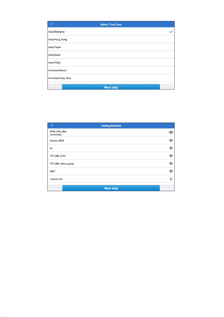
9. Choose Time Zone
Choose the time zone of your current location. The system will
automatically congure the time according to the time zone you
selected.
8
10. Connect Wi-Fi
The system will automatically search all available Wi-Fi networks. You
can choose the Wi-Fi needed.
*Note: Since the rst use of the scanner requires data interaction with
the server to activate it, the rst use must connect to WIFI; otherwise,
the diagnostic software will not be able to use, but after the activation
of the scanner, the diagnostic function can be used in the ofine state.
11. Enter workshop information
Here you can congure workshop information and an email address
(as the recipient by default when sharing reports or screenshots).
If you choose "Skip" in this step, it will automatically go to the next
step. In this case, go to "Settings" -> "Email" to set up it.

EN
9
12. User Agreement
Please read all the terms and conditions of the user agreement
carefully. Check “Agree all the above terms” and tap “Next” to
complete the registration process.
It will automatically jump to the Home Menu.

10
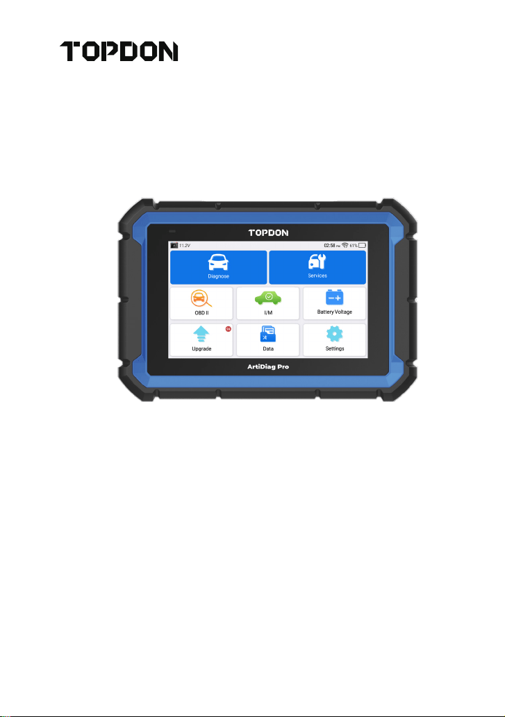
TOPDON ArtiDiag Pro has 8 major modules, including Diagnose,
Services, OBD II, I/M, Battery Voltage, Upgrade, Data, and Settings.
1. Diagnosis
TOPDON ArtiDiag Pro supports Smart Diagnosis and Manual
Diagnosis covering OBDII diagnosis, full system diagnosis for most
modern vehicles worldwide.
A diagnostic report will be automatically generated after the
diagnosis.
1.1 Smart Diagnosis (Auto-Detect)
Power on the ArtiDiag Pro. Tap “Settings”, and make sure the
“Automatic detection on connect” is on.
*Note: Alternatively, the user can also tap "Diagnose" -> "AutoDetect"
to start the smart diagnosis manually if the “Automatic detection on
connect” is Off.
Connect to the DLC’s port, and then turn the ignition key on. The
ArtiDiag Pro will enter the Smart Diagnosis mode automatically.
*Note: If the automatic detection can not identify the vehicle, please
try to connect to the network. Not all cars support the Auto-Detect
function due to auto manufacturers' settings.
1.1.1 Once the system successfully obtains the VIN (Vehicle
Identication Number), it will continue scanning the vehicle systems.
A diagnostic report will be automatically generated after the scanning
is completed.
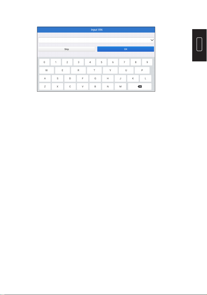
1.1.2 If the tablet fails to access the VIN information, the screen will
OPERATION INTRODUCTION
EN
11
display as follows:
Input the VIN and tap “OK”; the system will automatically identify the
vehicle model.
If the VIN is successfully decoded, it will perform Smart Diagnosis until
a diagnostic report is automatically generated. Otherwise it will enter
the Manual Diagnosis mode.
*Note:
•
A highly stable and solid network connection is recommended for
successful VIN access.
•
VIN characters may be capital letters A through Z and numbers 1
through 0; however, the letters I, O and Q would never be used in
order to avoid misreading. No signs or spaces are allowed in
the VIN.
1.2 Manual Diagnosis
If the tablet cannot obtain or analyze the VIN information, you can
also perform Manual Diagnosis. In this mode, you need to execute
the menu-driven command and follow the on-screen instruction to
proceed.
Refer to the owchart illustrated below to run the manual system
diagnostics.

12
Select “Diagnose”
Select Vehicle
Manufacturer
Select Vehicle Model
Select Scan Mode
Automatic System
Detection (System Scan)
Manual System Detection
(System Selection)
Select Test Function
Read Data
Stream
Actuation
Test
Special
Function
Clear Fault
Code
Read Fault
Code
Read Version
Information
*Note:
•
Before diagnosing, please make sure the corresponding vehicle
manufacturer software has been installed in the scanner.
•
The diagnostic menu may vary by the vehicle’s make, model, and
year.
EN
13
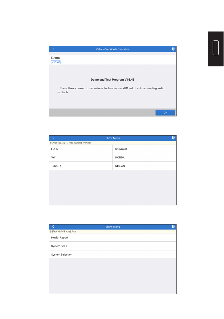
Take “Demo V15.43” as an example to demonstrate how to manually
diagnose a vehicle.
Tap “OK” to continue.
The following screen will appear:
Take “NISSAN” as an example to continue.
14
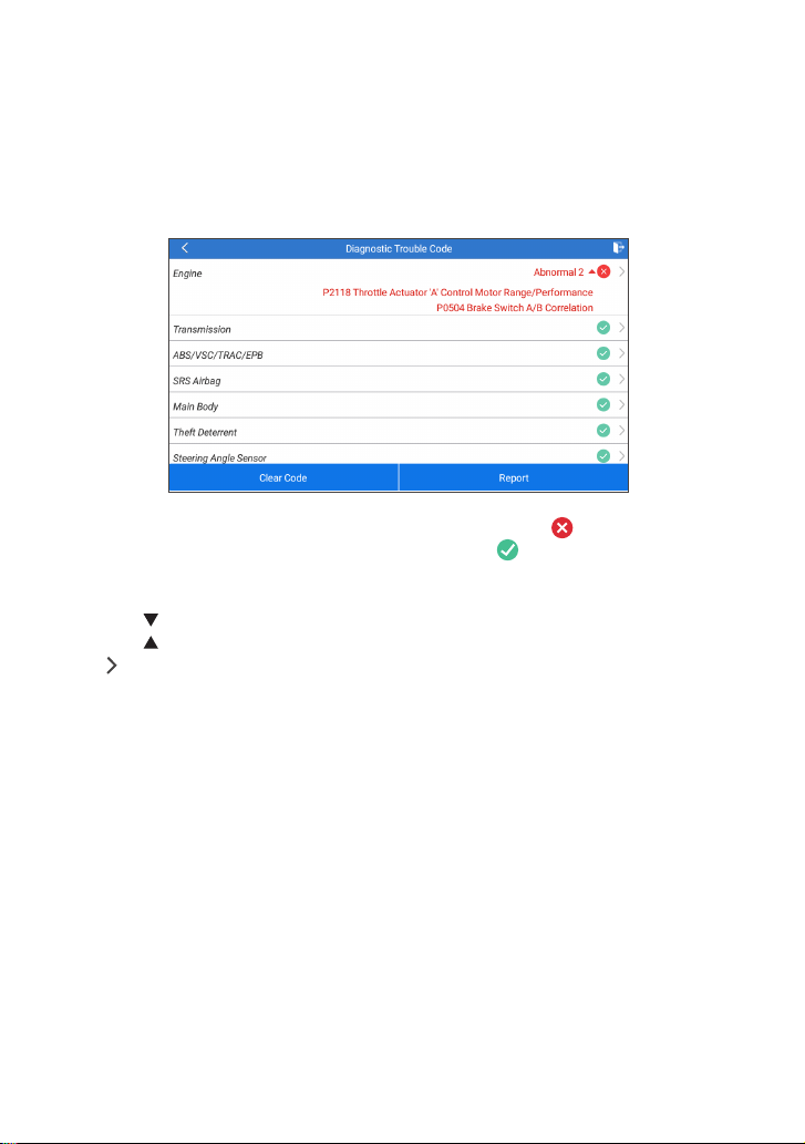
1.2.1 Health Report (Quick Test)
This function enables you to quickly access all electronic control units
of the vehicle and generate a detailed report about vehicle health.
Tap “Health Report”, and the system will start scanning the ECUs.
Once the scanning is complete, the following screen will appear:
The system with fault codes will be displayed in red ( ). The system
with no fault codes will be displayed in green ( ).
*Explanation of terms:
•
Tap to display the details of DTCs existing in the current system.
Tap to hide it.
•
: To select other test functions.
•
Report: To save the diagnostic result as a report.
•
Clear Code: To clear the existing diagnostic trouble codes.
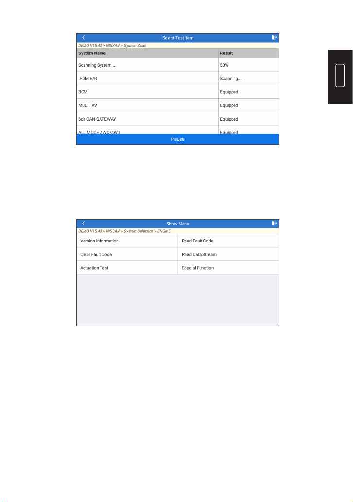
1.2.2 System Scan (Automatic System Detection)
This function will scan the vehicle test system automatically. Tap
“System Scan”. The following screen will appear:
EN
15
1.2.3 System Selection (Manual System Detection)
This function allows you manually select the system and perform the
related diagnostic functions.
Tap “System Selection”, and then select the desired system (take
“ENGINE” for example). The following screen will appear:
a. Version Information
This function can read the version information of system mode,
vehicle VIN, software and ECU.
b. Read Fault Code
This function displays the detailed information of DTC records
retrieved from the vehicle’s control system.
The following screen will appear:
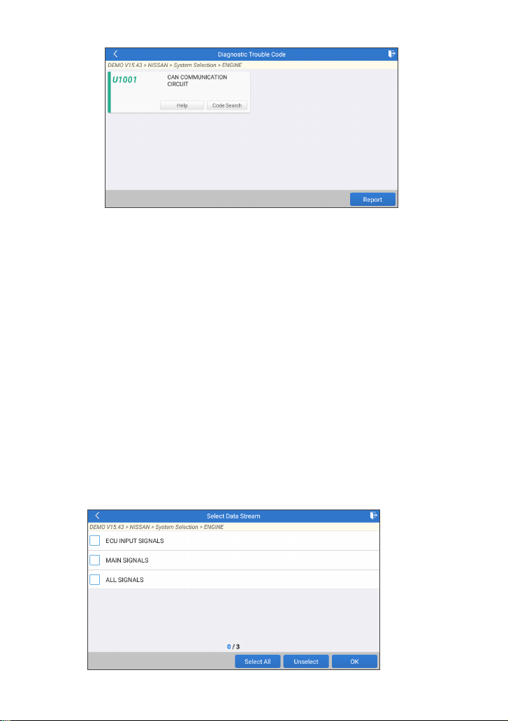
16
*Explanation of terms:
•
Freeze Frame: A snapshot of critical parameter values at the time
the DTC occurs.
•
Help: To view the help information.
•
Code Search: To search for more information about the current
DTC online.
•
Report: To save the current data in text format. All diagnostic
reports can be accessed from “Data” -> “Diagnostic Report”.
c. Clear Fault Code
This function can erase the codes from the vehicle. Please make sure
the vehicle’s ignition key is in the ON position with the engine off
before the operation.
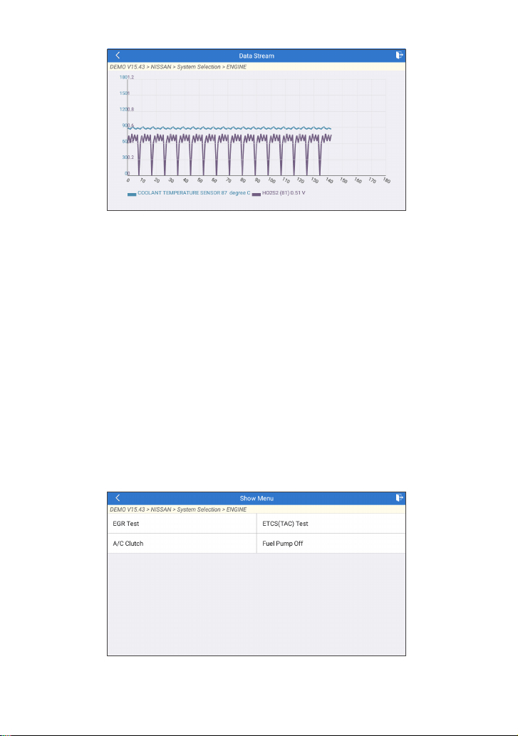
d. Read Data Stream
This option retrieves and displays live data and parameters from the
vehicle’s ECU.
The following screen will appear:

EN
17
After selecting the desired items, tap “OK” to enter the data stream
reading page.
The system will display the selected data streams in 3 modes available:
1) Value (default): Shows parameters with numbers and lists.
2) Figure: Displays parameters with wave patterns.
3) Combine: The graphs can be merged for easier comparisons.
Tap to view the parameters in wave patterns:
Tap “Combine” to merge values in waveform for easier comparisons.
Maximum 4 values can be selected at the same time.
18
Tap “Report” to save the current data as a diagnostic report. All
diagnostic reports can be accessed from “Data” -> “Diagnostic
Report”.
Tap “Record” to record and save the Live Data as valuable information
to help troubleshoot and diagnose. All diagnostic records can be
accessed from “Data” -> “Diagnostic Record”.
e. Actuation Test
This option is used to access vehicle-specic subsystem and
component tests. Available tests vary by vehicle manufacturer, year,
and model.
During the actuation test, the display tablet outputs commands to the
ECU in order to drive the actuators, and then determines the integrity
of the system or parts by reading the ECU data, or by monitoring the
operation of the actuators, such as switching an injector between two
operating states.
The following screen will appear:
Simply follow the on-screen instructions and make appropriate

EN
19
selections to complete the test.
Each time when an operation is successfully executed, "Completed"
will display.
f. Special Functions
This option offers coding, reset, relearn, and more service functions, to
help vehicles get back to functional status after repair or replacement.
Available tests vary by vehicle manufacturer, year, and model.
Some special functions can also be accessed by tapping the "Services"
on the Home Menu.
1.3 Diagnostic History
The tablet will record every details of a diagnostic session.
The History function provides direct access to the previously tested
vehicles. Users can resume from the last operation without the
necessity of starting from scratch.
Tap “History” in the “Diagnose” module. All diagnostic records will be
listed on the screen in a date sequence.
2. Maintenance Services
TOPDON ArtiDiag Pro features 29 of the most commonly used
maintenance services.
2.1 Maintenance Light Reset (Oil Reset)
This function enables you to reset the oil service lamp for the engine
oil life system, which calculates an optimal oil life change interval
depending on the vehicle driving conditions and weather events.
It needs to be performed in the following cases:
•
If the service lamp is on, run car diagnostics rst for troubleshooting.

20
After that, reset the driving mileage or driving time, so as to turn off
the service lamp, and enable a new driving cycle.
•
If the service lamp is not on, but you have changed the engine oil or
electric appliances that monitor oil life, you need to reset the service
lamp.
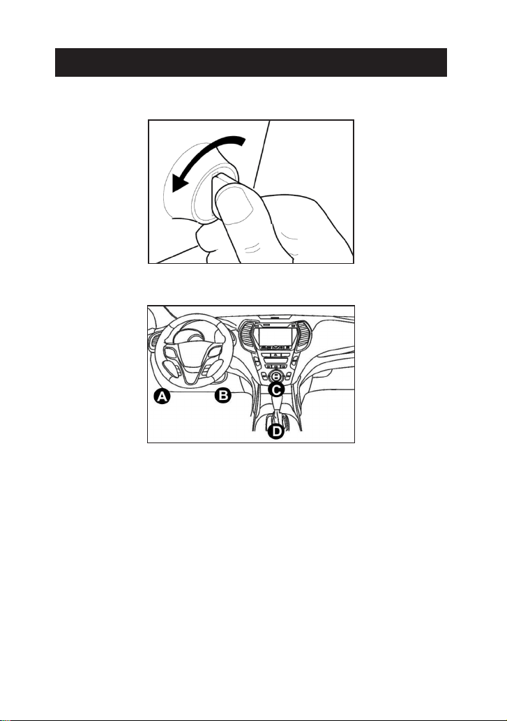
2.2 Steering Angle Reset (SAS Reset)
This function can reset the steering angle to zero to keep the car
running straight.
It needs to be performed generally after replacing the steering angle
position sensor, or after replacing the mechanical parts of the steering
system (such as steering gear, steering column, tie rod ball head,
steering knuckle), or after completing the four-wheel positioning,
body repair, etc.
2.3 Injector Coding (INJECTOR)
This function can write injector actual code or rewrite code in the ECU
to the injector code of the corresponding cylinder, so as to control or
correct the cylinder injection quantity accurately.
It needs to be performed in the following cases:
•
After the ECU or injector is replaced.
2.4 Battery Matching (BAT. RESET)
This function can reset the monitoring unit of the car battery, by
clearing the original breakdown information about the lack of battery
power to rematch the battery.
It needs to be performed in the following cases:
•
The replacement of the main battery needs to utilize battery
matching to clear the former information about the lack of power,
thus avoiding false information detected by the relevant control
module which may cause the failure of some electronic auxiliary
functions. For example, the vehicle automatically stops; the sunroof
can’t work by one key; electric windows can’t open and close
automatically.
•
The battery monitoring sensor uses the battery matching function
to rematch the control module with the monitoring sensor, so as
to detect the use of the battery power more accurately, and avoid
receiving wrong information from instrument prompts which will
cause false alarms.
2.5 ABS Bleeding
This function enables you to perform tests to check the operating
conditions of Anti-lock Braking System (ABS).

EN
21
It needs to be performed in the following cases:
•
When the ABS contains air.
•
When the ABS computer, ABS pump, brake master cylinder, brake
cylinder, brake line, or brake uid is replaced.
2.6 Throttle Matching (ELEC. THROTTLE RLRN)
This function initializes the throttle actuator so that the learning value
of the ECU returns to the initial state. By doing so, the movement of
the throttle (or idle motor) can be more accurately controlled, thus
adjusting the intake volume.
It needs to be performed in the following cases:
•
After replacing the electronic control unit, the relevant
characteristics of the throttle operation have not been stored in the
electronic control unit.
•
After the electric control unit is powered off, the memory of the
electric control unit’s memory is lost.
•
After replacing the throttle assembly, you need to match the
throttle.
•
After replacing or disassembling the intake port, the controlling of
the idle speed by the coordination between the electronic control
unit and the throttle body is affected.
•
The intake volume, and the idle control behavior has changed while
staying at the same throttle opening position, although the idle
throttle potentiometer behavior hasn’t changed.
2.7 Electronic Parking Brake Reset (BRAKE RESET)
This function helps you to replace and reset the brake pad.
It needs to be performed in the following cases:
•
The brake pad and brake pad wear sensor are replaced.
•
The brake pad indicator lamp is on.
•
The brake pad sensor circuit is short, which is recovered.
•
The servo motor is replaced.
2.8 DPF Regeneration (DPF REG.)
This function can help remove particulate matters from the trap by
using combustion oxidation methods to keep the performance of the
trap stable.
It needs to be performed in the following cases:
•
Replacement of the exhaust back pressure sensor.
•
Disassembly or replacement of the particle trap.
•
Removal or replacement of fuel additive nozzles.
•
Removal or replacement of catalytic oxidizer.
•
The DPF regeneration fault lamp is lit and matched after
maintenance.

22
•
Repair and replacement of the DPF regeneration control module.
2.9 Anti-theft Matching (IMMO)
This function can match the anti-theft key after replacing the ignition
key, ignition switch, instrument cluster, engine control unit (ECU),
body control module (BCM), and remote control battery.
2.10 Tire Pressure Reset (TPMS RESET)
This function can reset the tire pressure and turn off the tire pressure
fault indicator when the car tire pressure fault indicator light is on.
2.11 Suspension Level Calibration (SUS RESET)
This function can adjust the vehicle body height sensor for level
calibration after replacing the vehicle height sensor or control module
in the air suspension system, or when the vehicle level is not correct.
2.12 Headlight Matching (AFS RESET)
This function can initialize the adaptive headlight system. The
headlight system can decide whether to automatically turn on the
headlights based on the ambient light intensity, monitor the vehicle’s
driving speed, body posture, etc., and adjust the headlight lighting
angle.
2.13 Gearbox Matching (GEARBOX)
This function can complete the self-learning of the gearbox and
improve the shift quality, when the gearbox is disassembled or
repaired which may cause shifting delay or impact.
2.14 Sunroof Initialization (SUNROOF)
This function can set the sunroof lock off, close in rain, memory
function of sliding / tilting sunroof, outside temperature threshold,
etc.
2.15 Crank Position Sensor Adaptive Learning (GEAR LEARN)
This function can perform gear learning for the car, to turn off the
related Malfunction Indicator Light (MIL).
It needs to be performed in the following cases:
•
After the engine ECU, crankshaft position sensor, or crankshaft
ywheel is replaced.
•
The DTC “tooth not learned” is present.

EN
23
2.16 A/F Reset
This function is applied to set or learn air/fuel rate parameters.
2.17 EGR Adaption
This function is used to learn the EGR (Exhaust Gas Recirculation)
valve after it is cleaned or replaced.
2.18 AC System Relearn/Initialization
AC system relearn/initialization must be performed when the vehicle
AC ECU or actuator is replaced or the ECU memory is lost.
2.19 AdBlue Reset
After the diesel exhaust treatment uid (car urea) is replaced or lled
up, urea reset operation is required.
2.20 Coolant Bleed
Use this function to activate the electronic water pump before venting
the cooling system.
2.21 Engine Power Balance Monitoring
This function is used to monitor crankshaft acceleration in the power
stroke of each cylinder, to determine the relative power provided by
each cylinder.
2.22 High Voltage Battery Detection (HIGH VOLTAGE BATTERY)
This function is used for high voltage battery diagnosis and status
information detection.
2.23 Language Change
This function is used to change system language of vehicle center
console.
2.24 NOx Sensor Reset
NOx sensor is a sensor used to detect the content of nitrogen oxides
(NOx) in engine exhaust. If the NOx fault is re-initialized and the NOx
catalytic converter is replaced, it is necessary to reset the catalytic
converter learned value stored in the engine ECU.
2.25 Stop/Start Reset
This function is used to open or close the automatic Start/Stop
function via setting the hidden function in ECU (The precondition is
vehicle equipped with hidden function and hardware support).

24
2.26 Transport Mode
To lower vehicle power consumption, user may perform the following
operations: limit vehicle speed, not wake up the network for door
open and disable remote key etc. In this case, deactivating transport
mode is needed to recover vehicle being normal.
2.27 Tyre Reset
This function is used to set the size parameters of the modified or
replaced tire.
2.28 Windows Calibration
This function is used to perform door window matching to recover
the ECU initial memory, and recover the automatic ascending and
descending function of power window.
2.29 Seats Calibration
This function is applied to match the seats with memory function that
are replaced and repaired.

EN
25
3. OBDII/EOBD Diagnostics
This function presents a quick way to check for DTCs, isolate the cause
of the illuminated Malfunction Indicator Lamp (MIL), check monitor
status before emissions certication testing, verify repairs, and
perform other services that are emission-related.
Tap “OBD II” in the Home Menu after the tablet is properly connected
to the vehicle’s DLC port. The tablet will start an automatic check of
the vehicle’s computer to determine which type of communication
protocol it is using, then display the Monitor Status as follows:
Tap “OK”, the following OBDII function list appears.
3.1 Read I/M Readiness
This function checks whether or not the various emissions-related
systems on the vehicle are operating properly, and are ready for
Inspection and Maintenance testing.
It can also be used to check the Monitor Run Status, and to conrm if
the repair of a car fault has been performed correctly.

26
3.2 Read Live Data
This function retrieves and displays live data and parameters from the
vehicle’s ECU.
3.3 Read Freeze Frame
This function takes the snapshot of the operating conditions when an
emission-related fault occurs.
3.4 Read Fault Code
This function can identify which section of the emission control
system has malfunctioned.
3.5 Clear Fault Code
This function erases the codes from the vehicle, after retrieving codes
from the vehicle and certain repairs have been carried out.
Make sure the vehicle’s ignition key is in the ON position with the
engine off before the operation.
3.6 Test Results: On-Board Monitoring Test
This function retrieves test results for emission-related powertrain
components and systems that are not continuously monitored. The
test’s availability is determined by the vehicle manufacturer.
3.7 Control Operation of On-Board Component/System
This option is used to access vehicle-specic subsystem and
component tests. Available tests vary by vehicle manufacturer, year,
and model.
3.8 Read Vehicle Information
This function retrieves a list of information (provided by the vehicle
manufacturer) from the vehicle’s on-board computer.
This information may include: VIN (Vehicle Identication Number),
CID (Calibration ID) and CVN (Calibration Verication Number).
4. Battery Voltage
This function can measure the current voltage of the vehicle’s battery.
5. I/M
This function provides a quick access to the I/M Readiness diagnostics.
EN
27
6. Upgrade
A number will be displayed upon the “Upgrade” module in the Home
Menu indicating a new version of software is available.
It is strongly suggested to update the software on regular basis for
more functions and better service.
Once the download is nished, the software packages will be installed
automatically.
*Note: Stable and solid network connection is required.
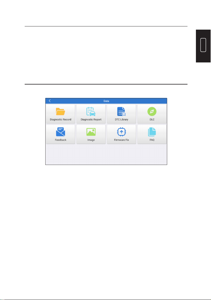
7. Data
Tap “Data” in the Home Menu. The following screen will appear:
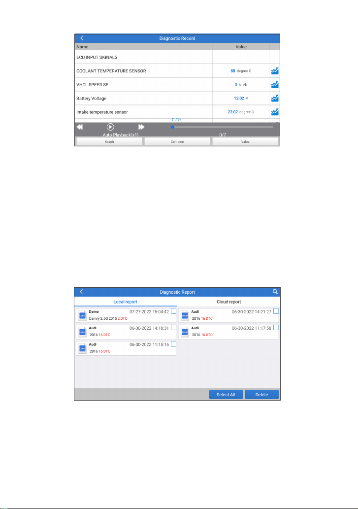
7.1 Diagnostic Record
This module stores the running parameters or waveform graphs the
user records.
28
*Explanation of terms:
•
Graph: Display parameters in waveform graphs.
•
Combine: Merge graphs for data comparison. Items will be in different
colors.
•
Value (default): Display the parameters as text in a list format.
•
Auto Playback: Automatic playback of the selected data stream
items. When in Auto Playback mode, the bar will change to “Frame
Playback”.
7.2 Diagnostic Report
This module stores all diagnostic reports generated in the process of
vehicle diagnostics.
7.3 DTC Library
This function allows you to retrieve the detailed descriptions of certain
DTC from the DTC database.

EN
29
7.4 DLC (Data Link Connector) Location
This function helps you to nd the location of the vehicle’s DLC.
7.5 Feedback
This function allows you to send the feedback of your diagnostic
problems to us for further analysis and troubleshooting.
There are 3 options:
1) Diag. Feedback: To send a tested vehicle diagnostic feedback.
2) History Feedback: To view all diagnostic feedback records.
3) Ofine Feedback: To view all diagnostic feedback logs that have
failed to be submitted, which will be uploaded again to the remote
server automatically once the tablet gets the stable network.
7.6 Image
All screenshots created in the vehicle diagnostic work will be saved in
this module.
7.7 Firmware Fix
Use this module to upgrade and x diagnostic rmware.
Do not cut power or switch to other interfaces in the upgrading
process.
7.8 FAQ
This module lists some frequently asked questions and answers
related to this tablet.
30
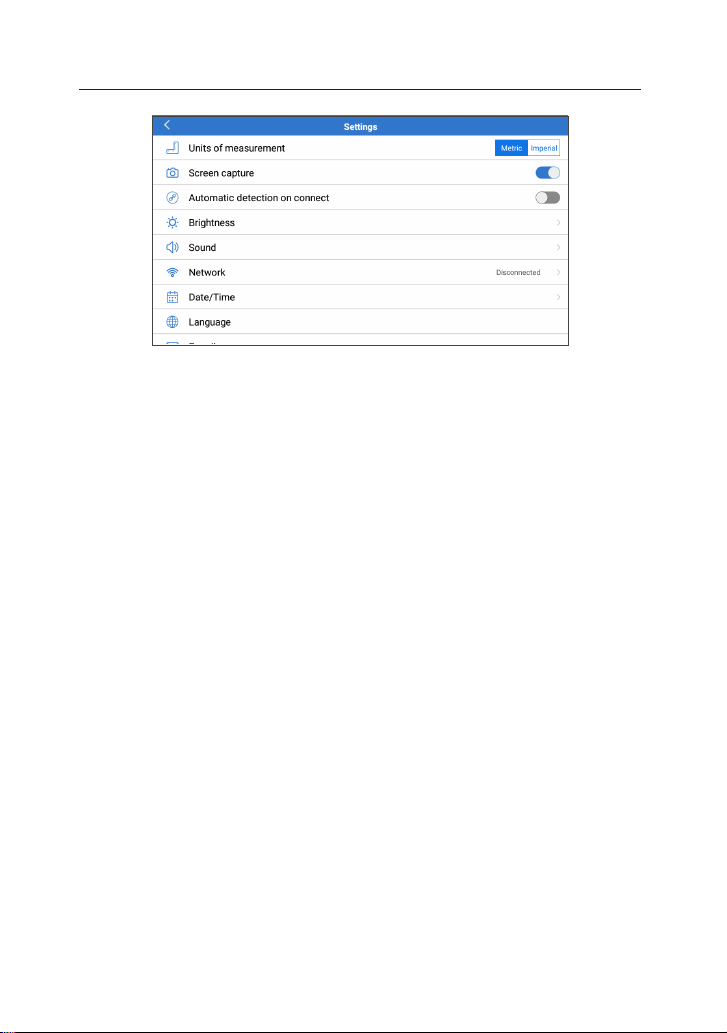
8. Settings
8.1 Units of Measurement
This option can set the measurement unit. Metric System and
Imperial System are available.
8.2 Screen Capture
This option can set the Screen Capture icon to be shown or not on the
screen.
8.3 Automatic detection on connect
This option enables you to determine whether to start an automatic
VIN detection once the tool is properly connected to the vehicle’s DLC.
8.4 Display/Brightness
This option allows you to set the standby time and screen brightness.
8.5 Sound
This option allows you to adjust the volume and other sound settings.
8.6 Network
This option allows you to set up Wi-Fi networks that can be connected.
8.7 Date & Time
This option allows you to set the system date & time.
8.8 Language
The tool supports multiple languages. You can use this option to set
the preferred language.

EN
31
*Note: After switching the language, please re-download all diagnostic
software, otherwise the system will use the English software by
default.
8.9 Exipration Date
This option allows you to check the expiration date of the diagnostic
software and renew the software subscription.
8.10 E-mail
This option can set up the default email address for receiving the
diagnostic reports or screenshots.
8.10 Recovery
This option can reset the tool to the default factory setting.
8.11 Clean Up
This option allows user to clear some cache les and free up storage
space.
8.12 About
This option displays the hardware conguration information of the
tool and the license agreement.

32
•
Always perform automotive testing in a safe environment.
•
DO NOT smoke near the vehicle during testing.
•
DO NOT place the diagnostic tool near the engine or exhaust pipe
to avoid damage from high temperatures.
•
DO NOT wear loose clothing or jewelry when working on an engine.
•
DO NOT connect or disconnect any test equipment while the
ignition is on or the engine is running.
•
DO NOT disassemble the code reader.
•
Engine parts will become hot when the engine is running. To
prevent severe burns, avoid contact with hot engine parts.
•
When an engine is running, it produces carbon monoxide, a toxic
and poisonous gas. Operate the vehicle ONLY in a well-ventilated
area.
•
Wear safety eye protection that meets ANSI standards.
WARNINGS
CAUTIONS
•
Please ensure that the vehicle battery is fully charged and the
scanner is rmly connected to the vehicle DLC to avoid erroneous
data generated by the scanner and diagnostic systems.
•
Please do not use the diagnostic tool during driving.
•
Keep clothing, hair, hands, tools, test equipment, etc. away from all
moving or hot engine parts.
•
Keep the scanner dry, clean, free from oil/water, or grease. Use a
mild detergent on a clean cloth to clean the outside of the scan tool,
when necessary.
•
Keep the scanner out of the reach of children.

EN
33
Q: System halts when reading the data stream. What is the reason?
A: It may be caused by a slackened connector. Please turn off the
tablet, rmly connect the connector, and switch it on again.
Q: Screen ashes at engine ignition start.
A: Normally caused by an electromagnetic disturbance.
Q: There is no response when communicating with the on-board
computer.
A: Please conrm the proper voltage of the power supply and check
the following:
•
Whether the throttle has been closed;
•
Whether the transmission is in the proper position;
•
Whether the water is the proper temperature.
Q: What to do if the system fails to start auto VIN detection?
A: Please check the following possible causes:
•
Whether the tool is properly connected to the vehicle’s DLC.
•
Whether the “Automatic detection on Connect” switch is OFF. If yes,
slide it to ON.
Q: Why are there so many fault codes?
A: Usually it’s caused by a poor connection or fault circuit grounding.
Q: How to upgrade the system software?
A:
1. Power the tool on and ensure a stable internet connection.
2. Tap “Settings” on the Home Menu, select “About” -> “Version”, and
tap “Detect the System Version” to enter the system upgrading
page.
3. Follow the on-screen instructions step by step to nish the process.
It may take a while to nish the upgrade depending on the
internet speed. The tool will automatically restart and enters the
Home Menu when the upgrade is nished.
Q: What if the tablet cannot be turned on even after recharging?
A: Please charge the tablet for at least 3 hours until the power LED
lights up.
FAQ

34
TOPDON's One Year Limited Warranty
TOPDON warrants to its original purchaser that the company's
products will be free from defects in material and workmanship for 12
months from the date of purchase (Warranty Period).
For the defects reported during the Warranty Period, TOPDON will
either repair or replace the defective part or product according to its
technical support analysis and conrmation.
TOPDON shall not be liable for any incidental or consequential
damages arising from the device's use, misuse, or mounting.
If there is any conict between the TOPDON warranty policy and local
laws, the local laws shall prevail.
This limited warranty is void under the following conditions:
• Misused, disassembled, altered or repaired by unauthorized stores
or technicians.
• Careless handling and operation's violation.
Notice: All information in this manual is based on the latest
information available at the time of publication and no warranty can
be made for its accuracy or completeness. TOPDON reserves the right
to make changes at any time without notice.
WARRANTY

EN
35
FCC Statement:
FCC ID: 2AVYW-ADPRO
This device complies with part 15 of the FCC Rules. Operation is
subject to the following two conditions: (1) This device may not cause
harmful interference, and (2) this device must accept any interference
received, including interference that may cause undesired operation.
Note: This equipment has been tested and found to comply with the
limits for a Class B digital device, pursuant to part 15 of the FCC Rules.
These limits are designed to provide reasonable protection against
harmful interference in a residential installation. This equipment
generates, uses and can radiate radio frequency energy and, if not
installed and used in accordance with the instructions, may cause
harmful interference to radio communications. However, there is no
guarantee that interference will not occur in a particular installation. If
this equipment does cause harmful interference to radio or television
reception, which can be determined by turning the equipment off
and on, the user is encouraged to try to correct the interference by
one or more of the following measures:
- Reorient or relocate the receiving antenna.
- Increase the separation between the equipment and receiver.
- Connect the equipment into an outlet on a circuit different from
that to which the receiver is connected.
- Consult the dealer or an experienced radio/TV technician for help.
This device is in compliance with the essential requirements and
other relevant provisions of Radio Equipment Directive 2014/53/EU.
The RF frequencies can be used in Europe without restriction.