Loading ...
Loading ...
Loading ...
40 - INSTALLATION 91477A872/A
The nozzles not provided are available at Authorised Service Centres.
Electrical connection
General information
Check the mains characteristics against the data
indicated on the plate.
The identification plate bearing the technical
data, serial number and brand name is visibly
positioned on the appliance.
Do not remove this plate for any reason.
The appliance must be connected to ground
using a wire that is at least 20 mm longer than
the other wires.
The appliance can work in the following modes:
• 220-240 V 1N~
Fixed connection
Fit the power line with an all-pole circuit breaker
with a contact separation distance sufficient to
provide complete disconnection in category III
overvoltage conditions, pursuant to installation
regulations.
For the Australian/New Zealand market:
The circuit breaker incorporated in the fixed
connection must comply with AS/NZS 3000.
Connection with plug and socket
Make sure that the plug and socket are of the
same type.
Avoid using adapters, gang sockets or shunts as
these could cause overheating and a risk of
burns.
Section cut from the countertop
Safety instructions for positioning and
installation
• Installation can be carried out on various
materials such as masonry, metal, solid
wood or plastic laminated wood as long as
they are heat resistant (>90°C).
• Veneers, adhesives or plastic coatings on
adjacent furniture should be temperature-
resistant (>90°C), otherwise they might
warp over time.
• If the piece of furniture does not have the
required recess opening, either it will have
to be cut or masonry work carried out by a
competent technician.
• The minimum clearance between exhaust
hoods and the cooking surface must be at
least the distance indicated in the exhaust
hood installation instructions.
• The minimum clearances must also be
respected for the edges of the hob on the
back as indicated in the assembly
instructions.
• If the appliance is to be installed above an
oven, the oven must be fitted with a cooling
fan.
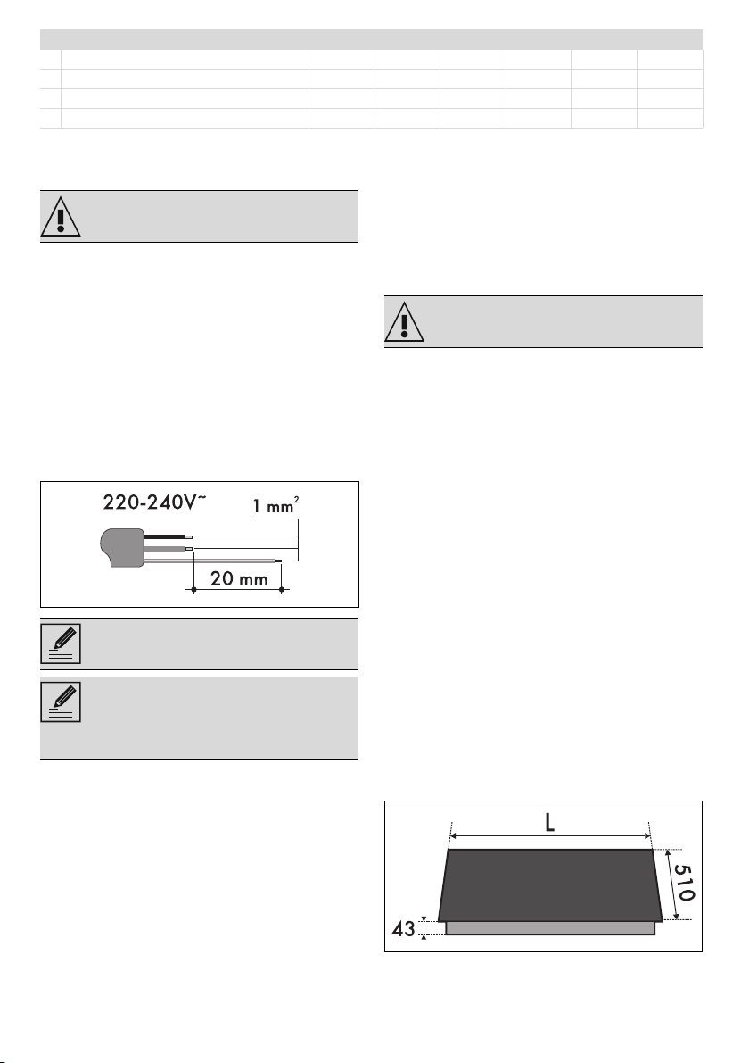
Appliance overall dimensions (mm)
7 Town gas G110 – 8 mbar AUX SR RR UR* UR2 int. UR2 ext.
Rated heating capacity (kW) 1.10 1.80 2.60 4.0 1.10 3.10
Nozzle diameter (1/100 mm) 132 165 210 290 132 240
Reduced flow rate (W) 400 500 750 1400 400 1400
Primary air (mm) 0.5 1 0.5 1.5 1 1
See General safety instructions.
The values indicated refer to the cross-
section of the internal conductor.
The aforementioned power cables are
sized taking into account the
coincidence factor (in compliance with
standard EN 60335-2-6).
See General safety instructions.
Loading ...
Loading ...
Loading ...