Loading ...
Loading ...
Loading ...
12
3. CONTROLS
3.1 AUTOMATIC MAIN WALL CONTROL INSTALLATION
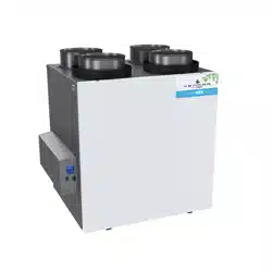
Cut a 2
7
/8” x 1¾” hole in a wall, at a convenient location for the control. Route the
included 40 ft cable (type 22/4) for the control from the unit to this hole. See figure at
right.
Temporarily place the control over the hole and mark both mounting screw hole
positions.
Remove the control, drill both screw holes (3/16” Ø) in wall and insert the included wall
anchors.
Ø 3/16", typ.
VC0213A
Unplug the ventilation unit.
VC0214
Mount the control to the wall using included screws.
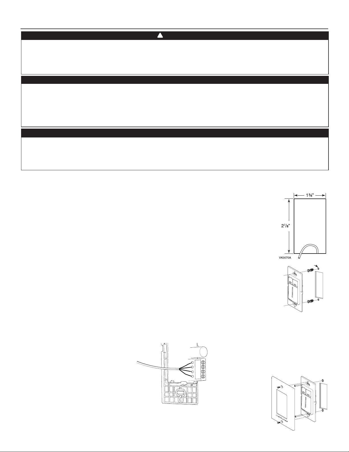
Gnd
D+
12V
D-
Strip the end of the cable to access the 4 wires (about 3”). Strip the end of each wire (about 1/4”). Use screws
to fi x the wires to the control terminals, regardless of the wire color or following the note below. Note
which wire color has been chosen for each terminal. Pull slightly on each wire to make sure they are firmly
connected.
NOTE: If the control is to be installed in an electric box, go to step .
Electrical wiring must be done by qualifi ed personnel in accordance with all applicable codes and standards.
Before connecting wires or making any connections, unplug the unit or switch power off at service panel and
lock service disconnecting means to prevent power from being switched on accidentally. Failure to cut power
could result in electrical shock or damage to the wall control or electronic module inside the unit. Always wear
safety glasses and gloves while performing these instructions.
Never install more than one main wall control per unit. Make sure that the wires do not short-circuit between
themselves or by touching any other components on the wall control. Avoid poor wiring connections. To
reduce the risk of electrical interference (noise), do not run wall control wiring next to control contactors or
near light dimming circuits, electrical motors, dwelling/building power or lighting wiring or power distribution
panel.
CAUTION
WARNING
!
If ducts have to go through an unconditioned space (e.g.: attic), always use insulated ducts to prevent condensation
formation inside and outside ducts, which could cause material damage and/or mold growth. Moreover, if
fresh air to building duct and/or stale air from building duct goes/go through an unconditioned space, the unit
must be set to operate continuously in cold conditions (below 10°C/50°F). Continuous air movement inside
ducts will prevent condensation formation. The unit can be stopped temporarily for maintenance and/or repair
purposes in such conditions (refer to section 2.4 for more details).
CAUTION
NOTE: We suggest to use the following wire
colors for each terminal:
Red wire for the ‘‘12 V’’ terminal,
Yellow for ‘‘D-’’,
Green for ‘‘D+’’ and
Black for ‘‘Gnd’’.
Loading ...
Loading ...
Loading ...