
Loading ...
Loading ...
Loading ...
8. Measure the clearance (A) between the interlock
bracket and the adapter with a feeler gauge.
The correct clearance is 0.030–0.060 in./0.75–
1.5 mm.
A
BC
9. Loosen the locknut (C) with a 1/2-in. wrench.
10. Set the correct clearance between the interlock
bracket and adapter.
a) Loosen or tighten the adjustment nut (B).
b) Measure the clearance.
c) Hold the adjustment nut (B) in the correct
position and tighten the locknut (C).
11. Engage and disengage the parking brakes a
minimum of 6 times to make sure that they
operate correctly. Refer to
To engage and
disengage the parking brake on page 13
.
12. Measure the clearance (A) between the interlock
bracket and adapter again.
13. Make sure that there is no tension in the parking
brake cables when the control levers are pulled
fully in the direction of the seat. Do not add
tension to the parking brake cables.
14. Install the parking brake panels and tighten the
bolts.
To charge the battery
• Charge the battery if it is too weak to start the
engine. Refer to
Battery charging times on page
31
for battery charging times.
• Use a standard battery charger.
CAUTION:
Do not use a boost
charger or start booster. A boost
charger or a start booster will cause
damage to the electrical system of
the product.
• Always disconnect the battery charger before
you start the engine.
To do an emergency start of the
engine
If the battery is too weak to start the engine, you can
use jumper cables to do an emergency start. This
product has a 12 V system with negative ground.
The product that is used for the emergency start
must also have a 12 V system with negative ground.
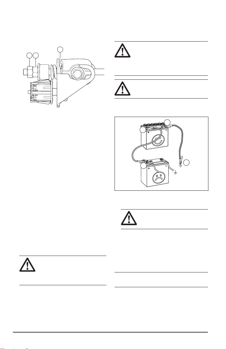
To connect the jumper cables
WARNING: Risk of explosion
because of explosive gas that comes
from the battery. Do not connect the
negative terminal of the fully charged
battery to or near the negative terminal
of the weak battery.
CAUTION: Do not use the battery of
the product to start other vehicles.
1. Connect one end of the red cable to the
POSITIVE battery terminal (+) on the weak
battery (A).
B
A
C
D
2. Connect the other end of the red cable to
the POSITIVE battery terminal (+) on the fully
charged battery (B).
WARNING:
Do not short circuit
the ends of the red cable against the
chassis.
3. Connect one end of the black cable to the
NEGATIVE battery terminal (-) on the fully
charged battery (C).
4. Connect the other end of the black cable to a
CHASSIS GROUND (D), away from the fuel tank
and the battery.
To remove the jumper cables
Note:
Remove the jumper cables in the opposite
sequence to how you connect them.
1. Remove the BLACK cable from the chassis.
2. Remove the BLACK cable from the fully charged
battery.
3. Remove the RED cable from the 2 batteries.
20
2171 - 001 - 14.06.2023
Loading ...
Loading ...
Loading ...